Article

Experimental Investigation of the Derivative Cutting When Machining AISI 1045 with Micro-Textured Cutting Tools

1
Machining Research Laboratory, University of Ontario Institute of Technology, Oshawa, ON L1G 0C5, Canada
2
Department of Mechanical and Aerospace Engineering, College of Engineering, United Arab Emirates University, Al Ain 15551i, United Arab Emirates
*
Author to whom correspondence should be addressed.
Metals 2023, 13(9), 1587; https://doi.org/10.3390/met13091587
Submission received: 8 August 2023 / Revised: 30 August 2023 / Accepted: 8 September 2023 / Published: 13 September 2023

Abstract

:
In the context of satisfying sustainability requirements nowadays, dry machining is one of the ideal strategies to eliminate the environmental and human health burdens of machining processes. In addition, micro-textured cutting tools are used to improve the performance of dry machining processes. Micro-textures reduce the chip-tool contact length and thus reduce friction and heat, which results in fewer cutting forces and temperature. However, the action of micro-cutting of the bottom side of the chip, which is known as derivative cutting, cuts down the gains of using textured tools, where derivative cutting leads to higher cutting forces, heat, and tool wear. This study aimed to investigate the effects of significant texture design parameters (i.e., micro-groove width) when cutting AISI 1045 steel using different machining parameters (i.e., 75 m/min and 150 m/min of cutting velocity, 0.05 and 0.10 mm/rev of feed). Three different textured cutting tool designs were prepared using the laser texturing technique and then utilized in machining experiments. In addition, the measured machining outputs were forces, power consumption, flank wear, and surface roughness. There were no marks for the derivative cutting when using the textured cutting tool with the narrowest micro-grooves according to the obtained microscopical images after the machining tests. In addition, the textured cutting tool, which included the narrowest micro-grooves, showed better performance compared to the non-textured cutting tool and the other textured tool designs in terms of cutting and feed forces, power consumption, flank tool wear, and surface roughness at the used cutting conditions. This confirmed that the careful optimal design of the micro-textured tools can reduce or eliminate the severity of the derivative cutting, and thus improve the overall machining performance.

1. Introduction

Dry machining is one of the ideal strategies to eliminate the environmental and human health impacts of the machining processes. This comes from eliminating all of the impacts associated with using cutting fluids [1]. On the other hand, there are drawbacks related to dry machining, such as high friction forces and high cutting heat generation. Accordingly, researchers have paid great attention to optimizing the machining parameters to eliminate the drawbacks of dry machining. Many studies have provided new designs of cutting tools to overcome the disadvantages of dry machining, such as textured cutting tools [2,3]. Surface texture is defined as the generation of micro/nano-scale textures of different shapes on the rake or flank faces. These textures are utilized to achieve the following functions [4,5]: (a) reduce the friction in the chip-tool interface by decreasing the chip-tool contact length, resulting in less frictional force and cutting temperature; (b) reserve the lubricants during the machining process (i.e., acting as micro-pools), where the cutting fluids are trapped in the textures’ cavities to produce no direct contact between the chip and the tool; (c) trap the debris generated by different wear mechanisms such as abrasive and adhesive wear mechanisms to minimize the ploughing actions in tool-chip and tool-workpiece zones which leads to less tool wear and better surface roughness.
There are various techniques for generating different shapes of textures over the rake and flank surfaces of cutting tools. The textures can be linear grooves perpendicular, parallel, or cross-pattern orientation with respect to the chip direction [6]. The textures can be in the shape of round and square dimples. In addition, the linear grooves can be perpendicular or parallel to the main cutting edge. The surface texturing techniques vary from thermal energy micro-machining techniques to mechanical micro-machining techniques [4]. Examples of thermal energy micro-machining are laser surface texturing and electro-discharge micro-machining. Generally, the laser technique has the required capabilities to generate textures for different types of substrates. Laser techniques can be utilized to generate different shapes of textures, such as linear grooves, cylindrical dimples, and square pyramids [7,8]. In micro-Electro Discharge Machining (micro-EDM), material removal occurs due to the melting and vaporization at the point of discharge. This technique has been utilized to generate holes on the rake face of the carbide tool [9]. For mechanical micro-machining techniques, micro-grinding is the most effective technique for generating linear grooves. Xie et al. [10] used a grinding diamond wheel with a V-tip to generate linear microgrooves over the rake face of the carbide tool. Moreover, the hardness tester is used to apply textures as a result of the indentation on the cutting tool surface. This technique can generate different shapes of textures, such as the conical, round, and square pyramid, by utilizing different hardness testers, such as Rockwell and Vickers hardness testers [11].
For the textured cutting tools, the contact length (i.e., frictional length) at the chip-tool interface is decreased according to the type and the dimensions of the textures. This results in reducing the frictional force, which is a function of the frictional length. Sharm et al. [12] utilized carbide tools with elliptical grooves, parallel grooves to the cutting edge, and linear grooves to study the reduction in cutting forces. After that, these grooves were filled with a MoS2 solid lubricant. Dry Turning experiments were carried out using these tools for cutting 45# steel. The results revealed that the reduction in the cutting forces was between 15–25% when using the textured tools compared to the non-textured tool. In addition, Koshy et al. utilized micro-EDM techniques to generate areal and linear textures on the rake face of T-15 grade high-speed steel inserts to investigate the effectiveness of textured tools in reducing friction [13]. In the same study, cutting and feed forces were measured when machining the annealed 1045 steel and 6061 aluminum workpieces. It was found that the reduction of the feed and cutting forces was 30% and 13%, respectively. Fatima et al. [14] used the femtosecond laser technique to apply slot structure grooves over the rake and flank faces of an uncoated cemented carbide tool. Orthogonal cutting tests were carried out to machine a tube of AISI/SAE 4140 plain carbon steel. The observed average reductions in the cutting and feed forces were 10% and 23%, respectively. Thomas et al. [11] reported that the reduction of the main cutting forces when using the textured tool for turning mild steel (EN3B) and aluminum (AA 6351) varied from 2% to 22% according to the shape of the textures and the operated cutting speed.
In the context of meeting environmental regulations, textured tools are promising candidates to replace machining with cutting fluids to reduce the cutting temperature. Liu et al. [15] utilized a textured cemented carbide tool to turn green alumina ceramics. The obtained results showed that there was an obvious effect of the textured tool to reduce flank tool wear compared to the non-textured tool. The applied parallel micro-grooves helped to remove the hard particles at the tool-chip interface, which was beneficial in reducing the abrasive effect. Niketh et al. [16] studied the effect of textured drill bits to reduce sliding friction in the drilling application of Ti-6Al-4V. The round dimple texture achieved a lower and more stable coefficient of friction according to the conducted pin and disc tests compared to the grooved and plain surfaces. For drilling with the conventional drill bit, the maximum reduction in thrust force was 10.68% when using a margin-textured drill. In terms of the surface quality of the machined holes, the holes machined with margin-textured drill bits showed lower burr formation. In a previous study [11], improvements of 15.86% and 23.21% were observed in surface roughness when machining mild steel and aluminum, respectively. In addition, the dimple texture on the rake face showed better performance for stabilizing the BUE compared to the non-textured tool when machining plain carbon steel SAE 1045 with an uncoated cemented carbide tool [17].
Despite the previously mentioned advantages of the textured cutting tool, it was found that there is an additional cutting of the bottom side of the chip when using the textured cutting tools [18]. This micro-cutting by the micro-groove edges is defined as a “Derivative cutting phenomenon”. This micro-cutting phenomenon by the micro-grooves edges presents additional forces and cutting temperatures. Therefore, the derivative cutting phenomenon cuts down the benefits of using textured cutting tools. Duan et al. [18] attempted to study the derivative cutting when dry turning medium carbon steel (AISI 1045) utilizing carbide tool with one micro-groove over the rake face. The obtained results showed higher forces and coefficients of friction associated when using the micro-grooved tool compared to the conventional tool, especially at the beginning of the cutting process. In addition, it was found that derivative cutting induces adhering of the chip’s material to the texture’s edge in the direction of the chip flow. In addition, the derivative cutting phenomenon leads to filling the cavity of the micro-grooves with the chip material. Thus, the cavity of the micro-grooves may be blocked at a certain time during the machining process, as noticed in [7,18]. This means that there will be a high affinity between the main chip and the blocked chip material inside the micro-groove’s cavities. Therefore, some particles of the chips (existing in the texture cavities) will stick on the bottom side of the newly generated chip and result in a high wear rate over the rake face. In another attempt [19] to study derivative cutting phenomena, cutting forces, tool wear, and chip formation were analyzed when dry-turning AISI H13 steel. The results revealed the negative effect of the derivative cutting phenomenon on the cutting forces. Higher forces of the textured tools were obtained compared to the conventional tools at all cutting speeds. For tool wear behavior, many plowing grooves near the cutting edge were found. In addition, crater wear and seizure zones were found due to the adhesion of the workpiece material to the rake face. Moreover, dragging damage was observed on the chip bottom side produced by textured tools. The derivative cutting phenomenon was investigated in [20] when cutting Ti-6Al-4V using different machining strategies. These strategies were plain dry environment along with the non-textured tool, plain dry environment with laser textured cutting tools, textured tool with MQL-vegetable oil, and textured tool with MQL-alumina-DI water nano-fluid. The microscopic images of the used textured tool showed that filled and semi-filled textures were observed due to the derivative cutting phenomenon. This resulted in a higher contact area and generated heat, especially in a dry environment. Furthermore, derivative cutting has been directly observed in situ in [
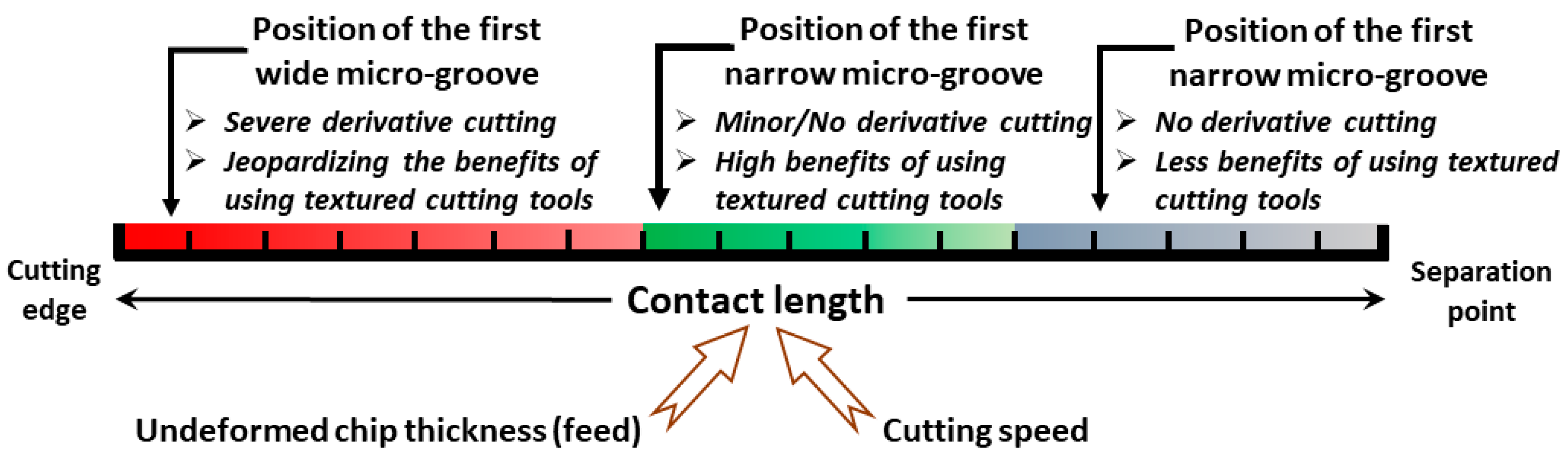
21] using particle image velocimetry. Shaping experiments were conducted with Al-1100. The results showed a high reduction in the frictional force at 30 µm and 50 µm undercut chip thickness. Slight reductions were obtained at 15 µm and 75 µm where the micro-groove was completely within the sliding and sticking contact regions, respectively. These results revealed that the frictional forces depend on the relative distance of the micro-groove from the cutting edge and its relationship with the undercut chip thickness.
The majority of previous studies focused on the benefits of using textured tools on cutting forces, temperature, chip formation, and tool wear. In addition, they showed the additional gains of integrating the textured tool with different cooling strategies. While a limited number of studies have explored the influence of texture parameter dimensions on the performance of textured cutting tools [18,
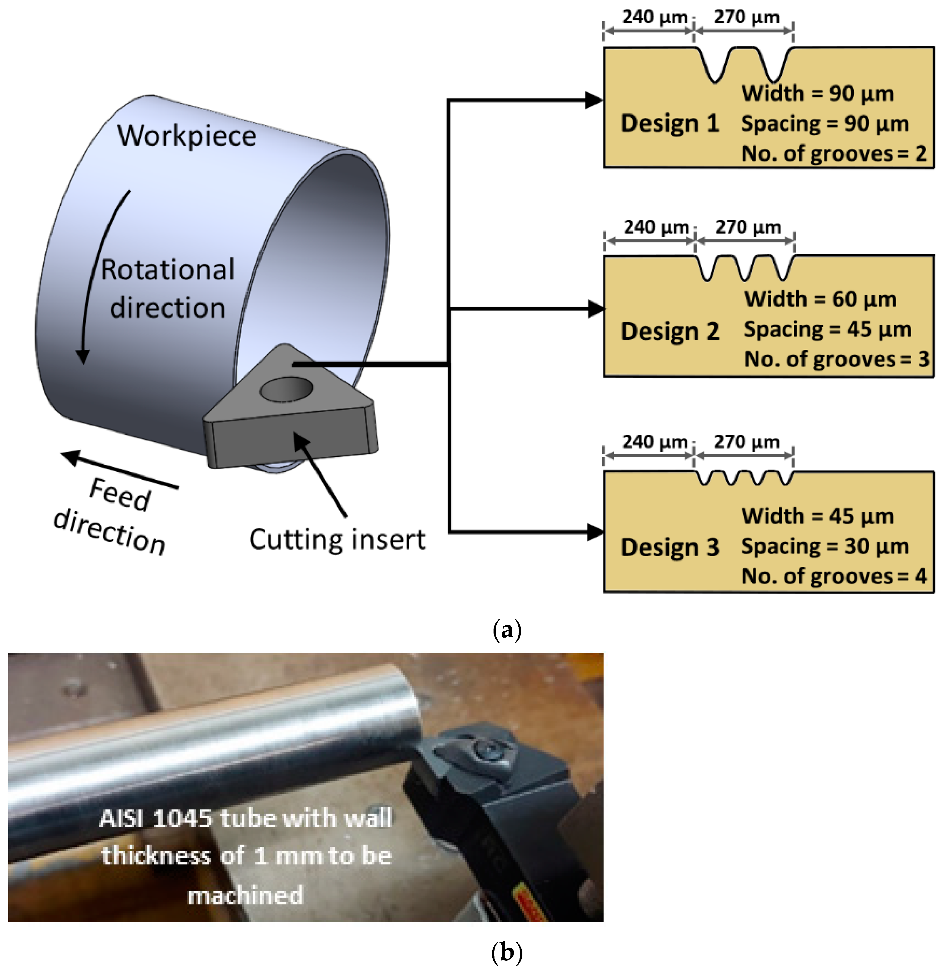
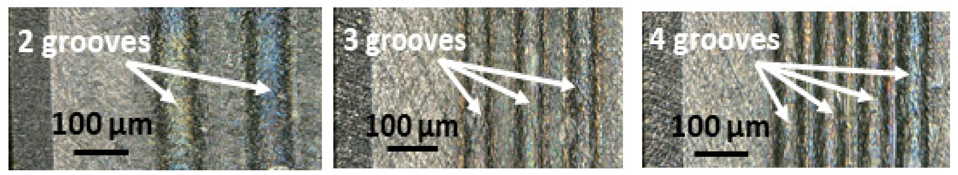
22], the fundamental physics of the process and the impact of different design parameters have not been thoroughly elucidated. Consequently, there is a clear need to comprehend the underlying phenomena and provide recommendations to ensure the reliable performance of such tools. Moreover, it is imperative to investigate the effects of different machining parameters, such as cutting velocity and feed, when employing various designs of textured cutting tools with different texture dimensions. This investigation should encompass not only the examination of forces but also the assessment of the effects of micro-textured tools on tool wear, surface roughness, and power consumption. By comprehensively studying these aspects, a more complete understanding of the potential benefits and limitations of micro-textured tools can be achieved. Thus, this paper aims to investigate the effects of significant texture design parameters when cutting AISI 1045 steel using different machining parameters. Each tool design was used under four different cutting conditions (a total of 16 experiments). According to the experimental findings provided in Section 3, the authors have provided a mechanism of machining using textured cutting tools, including recommendations to minimize the derivative cutting. The recommendations and mechanisms proposed based on the experimental findings highlight the potential of micro-textured tools to serve as sustainable options in the machining industry, particularly when used in dry environments. Thus, this paper underscores the practical implications and significance of micro-textured cutting tools in achieving sustainable machining practices.

2. Experimentation

In a previous study [23], it was found that the position and width of micro-textures are the most significant design variables impacting the derivative-cutting phenomenon. In addition, it was recommended to use a far position from the cutting edge along with the narrowest available width to achieve the optimal texture design. The results of additional machining experiments are presented in this paper to further investigate the impact of these important dimension parameters on various machining parameters (specifically, cutting speed and feed).

2.1. Experimentation Plan

All experiments were carried out on a Standard Modern N/C 17 lathe (10 HP, Racer Machinery International Inc., Cambridge, Canada). These experiments were conducted with a non-textured tool and three distinct textured tool designs at various cutting speeds and feed, as shown in Table 1. Each tool design was used under four different cutting conditions (total of 16 experiments). These cutting conditions included cutting speeds of 75 m/min and 150 m/min, feed of 0.05 mm/rev and 0.1 mm/rev (i.e., low cutting speed and low feed, low cutting speed and high feed, high cutting speed and low feed, and high cutting speed and high feed). It should be stated that both feed and micro-groove position parameters were dependent on the chip-tool contact length and the normal stress distribution. The normal stress distribution at the tool-chip interface varied as the feed was altered (i.e., undeformed chip thickness). Thus, the first micro-groove on all utilized textured cutting tools was positioned 240 microns from the cutting edge. Accordingly, the dependent relationship between the feed and micro-groove position could be properly investigated. In other words, using a textured cutting tool with the same micro-groove position at different cutting conditions can address the effect of the different micro-groove positions. Furthermore, the utilized textured tool designs included different values of the micro-groove width to investigate their effects on the machining outputs. As shown in Figure 1a, the three utilized texture designs had different groove widths, spacing between grooves, and number of grooves, while for all designs, the distance from the cutting edge to the first groove was 240 μm, the spacing of the total grooves was 90 μm, and the total width of all micro-grooves was 180 μm. Design 1 included 2 micro-grooves with a width of 90 μm and spacing between these two micro-grooves of 90 μm. Design 2 included 3 micro-grooves with a width of 60 μm and spacing between every two adjacent micro-grooves of 45 μm. Finally, design 3 included 4 micro-grooves with a width of 45 μm and spacing between every two adjacent micro-grooves of 30 μm. All of these microgrooves were parallel to the cutting edge. The considered cutting tools were used in orthogonal cutting (i.e., tube turning) experiments, as shown in Figure 1a,b. The cutting edge and micro-grooves were perpendicular to the chip motion over the rake face in the orthogonal cutting. This was to simplify the phenomena of micro-cutting associated with textured cutting tools. These orthogonal cutting experiments were conducted on a tube of AISI 1045 with a 30 mm diameter and 1 mm wall thickness. In addition, the cutting length of each test was 12.5 m. In these machining experiments, the feed and cutting forces, power consumption, flank tool wear, and surface roughness were measured. In addition, each test was repeated 3 times, and the average measured machining response for each test was obtained and used for the analysis.
Through the execution of experiments, the cutting and feed forces were measured to ascertain whether the derivative cutting phenomenon existed or not. Power consumption was measured to environmentally evaluate the utilization of these textured tool designs [24,25]. In addition, after each trial, a 2D microscopical image of the cutting tool’s rake face was captured.

2.2. Workpiece Material and Cutting Insert

The workpiece material of carbon steel AISI 1045 with a Brinell hardness of 180 (HB) was selected to conduct the experimental plan. AISI 1045 material has good machinability in a dry environment. It is also used in various wide industrial applications, ranging from small to mass production scale. In the experimentation phase, the uncoated mixed ceramic inserts with a triangular shape of 6 cutting edges (TNGA160408T01020 650) and the tool holder (DTGNR 2525M 16) with a rake angle of −6° were used. This was a chamfer honed insert (honing width of 0.07 mm and honing angle of 30°). The chemical composition of this mixed ceramic tool was 70% of Al2O3 and 30% of TiC [26].

2.3. Preparation of the Cutting Inserts

The laser ablation micro-machining process was utilized to generate different textured cutting tool designs. There are three main operations during the laser ablation process. First, the laser beam is concentrated on the rake face of the cutting insert. The absorbed photo energy in the upper thin layer of the sample should be higher than the threshold value to achieve material decomposition. Material decomposition occurs in the second operation after reaching the threshold energy due to photo-thermal and photo-chemical degradation. The decomposed particles are then ejected, forming ablation. The evaporated particles of this ablation plume are removed in the final operation, and the non-evaporated particles fall back to or near the ablated area in the form of debris. The micro-grooves of the textured cutting tools used in the experimentation phase were generated using a Ytterbium-doped pulsed fiber laser (YDFLP) system (i.e., solid-state laser). The pulse duration of this system was in the range of nanoseconds. The laser parameters for the three different textured cutting tool designs were obtained through several rounds of laser tests. Initial laser parameters were used to generate each textured design. Then, the obtained micro-grooves of each design were measured using a digital optical microscope (KEYENCE VHX-1000, Keyence Corp., Osaka, Japan). The laser’s parameters were adjusted continuously until the microgrooves were within the acceptable range (±10 µm). The used laser power, frequency, and pulse duration for obtained 3 designs were of the obtained 3 designs were 10 watt, 100 KHz, and 50 ns, respectively. The laser scanning speed was 500 mm/s, 750 mm/s, and 1000 mm/s for design 1, design 2, and design 3, respectively. In addition, the number of laser passes to generate each groove was 2, 1, and 1 for design 1, design 2, and design 3, respectively. Figure 2 shows 2D microscopical images of the micro-grooves are shown in Figure 2. The shape of the generated grooves was a circular shape. In addition, the depth of the micro-grooves in the three studied designs varied between 10 and 12 μm.

2.4. Machining Characteristics Measurements

The cutting and feed forces were captured using a Kistler 9251 A dynamometer (Kistler Group, Winterthur, Switzerland). This dynamometer captured the signals that needed to be amplified using three Kistler (KCA5010B) charge amplifiers. These amplifiers were connected to National Instrument data acquisition (NI USB-6221 BNC). LabView software (NXG 5.1) was used to read the recorded charges. A power sight manager (Summit Technology, Florida, FL, USA) was utilized to measure the power consumption of each machining test. To measure power consumption, three current probes and three voltage leads were connected to the three electricity phases of the lathe machine. The other ends of these current probes and voltage leads were connected to the power logger (PS2500). Power sight manager software displayed the power consumption measurements. This power sight manager measured the three phases’ voltages and currents: apparent power, reactive power, true power, and power factor. The power consumption values were based on measurements of true power. The surface roughness of the machined surface was measured for each test. The surface roughness tester Mitutoyo SJ.201 (Mitutoyo, Japan) was used to obtain the surface roughness values. In this study, surface roughness was evaluated using the arithmetic average surface roughness (Ra). A cut-off length of 0.25 mm was used for the surface roughness measurements. In addition, five measurements were obtained at different locations after each test. The average of these five measurements was utilized to determine the value of the surface roughness of each test. A digital optical microscope KEYENCE VHX-1000 was used to capture and measure the flank tool wear. This microscope has a magnification option of up to 5000×. In addition, this optical microscope was utilized to generate the 3D topographies of the micro-grooves surfaces in this study.

3. Results and Discussion

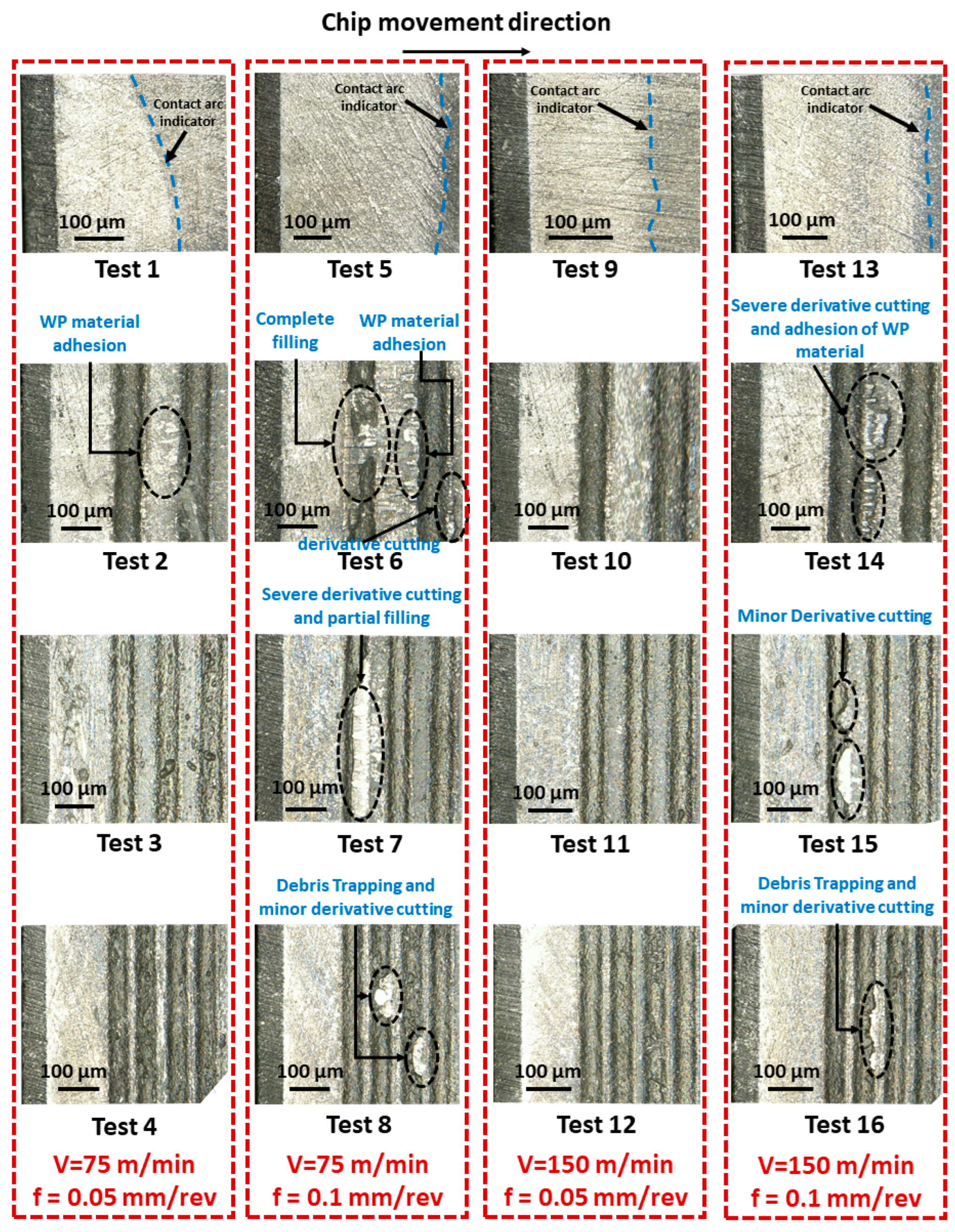
Figure 3 shows the 2D microscopical images of the 16 machining tests using different cutting tools, as presented in Table 1. Different contact lengths can be seen in the microscopical images for the tests when non-textured cutting tools were used (tests 1, 5, 9, and 13). These contacts were about 318 μm, 519 μm, 264 μm, and 416 μm for test 1, test 5, test 9, and test 13, respectively. The normal and shear stresses at each test under the corresponding cutting conditions are responsible for varying the observed contact lengths. This confirms that the use of textured cutting tools with the same micro-groove position at different cutting conditions (i.e., different contact lengths) can address the effect of the micro-groove position. In other words, it is the same effect of using textured cutting tools with different micro-grooves positions in the same cutting condition (i.e., same contact length). The undeformed chip thickness (i.e., feed in the case of orthogonal cutting) played the dominant role in determining the contact length, where increasing the feed value was accompanied by increasing the contact length, as shown in the first four images in Figure 3. This is well in line with the previously developed models for the contact length presented in [27]. However, increasing the cutting velocity reduced the contact length of the chip over the rake face of the cutting tool. This agrees with the finding presented in [28] that a higher cutting velocity results in a lower coefficient of friction and a shorter contact length.
Evidence of workpiece adhesion in the interstices between the two micro-grooves and the absence of derivative cutting can be seen in the micrograph for test 2 (when the first texture design was used). The first texture design showed a complete filling in the cavity of the first micro-groove with chip material, as shown in the microscopic image of test 6 (i.e., longest contact length at low cutting velocity and high feed). In addition, in test 6, there were marks of the derivative cutting at the edge of the second micro-groove, and there is a workpiece adhesion on the spacing between the two micro-grooves. For test 10 (i.e., design 1 at a high cutting velocity and low feed), there are no marks for derivative cutting. However, in test 14 (i.e., design 1 at high cutting velocity and high feed), both the derivative cutting marks and the material adhesion to the workpiece were visible. Regarding the second textured cutting tool design, there were no marks for derivative cutting in tests 3 and 11 when the low feed with low and high cutting velocity, respectively, was utilized. Severe derivative cutting and partial filling in the cavity of the first micro-groove was presented in test 7 (i.e., design 2 at low cutting velocity and high feed), as shown in Figure 3. There were marks of minor derivative cutting that can be seen in test 15 (i.e., design 2 at high cutting velocity and high feed).
Tests 4 and 12 using textured cutting tool design 3 at the low feed with low and high cutting velocities, respectively, showed no marks for the derivative cutting, similar to design 2. In addition, when using design 3 at high feed, there were minor marks for derivative cutting and the trapping of the cutting debris, as shown in the microscopical images for tests 8 and 16 at low and high cutting velocities, respectively. The micro-groove with a narrow width (design 3) reduced the incidence of derivative cutting with the complete and partial filling actions observed with design 1 at high feed and with design 2 at high feed and low cutting velocity. These findings are consistent with the outcomes of simulation tests from a previous study [23], illustrating that the utilization of textured cutting to eliminate derivative cutting diminishes the contact length between the rake face and the resultant chip.

3.1. Cutting and Feed Forces
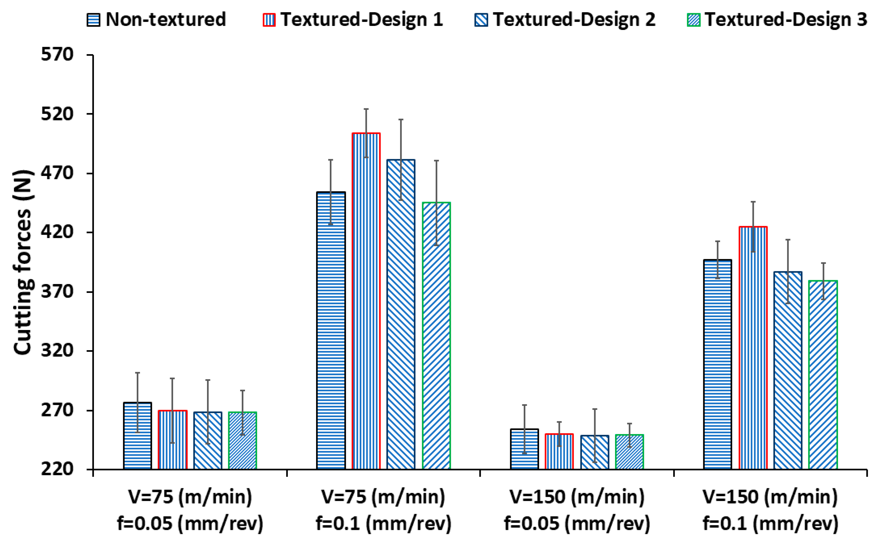
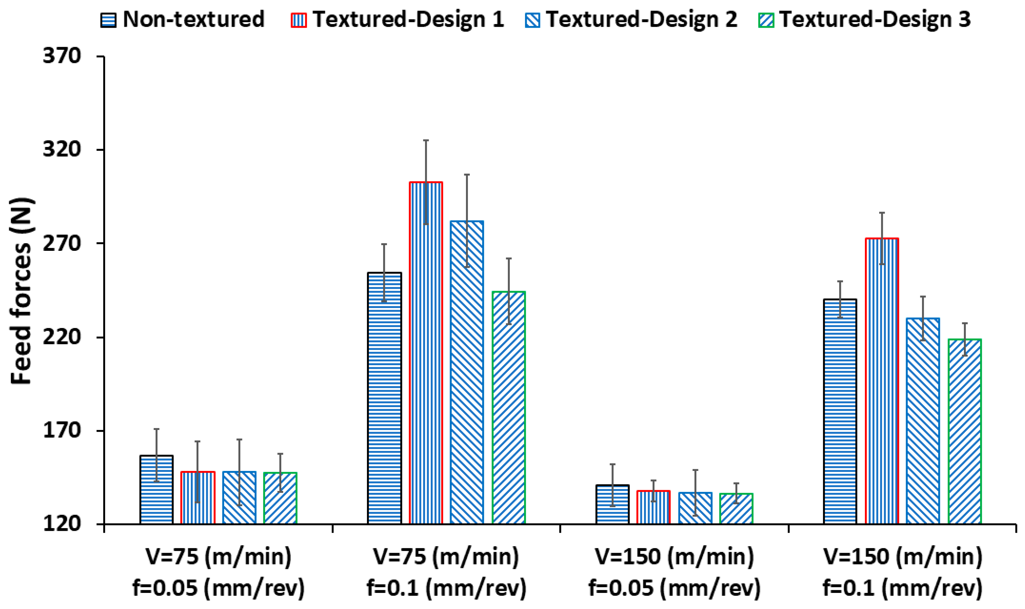
Figure 4 and 
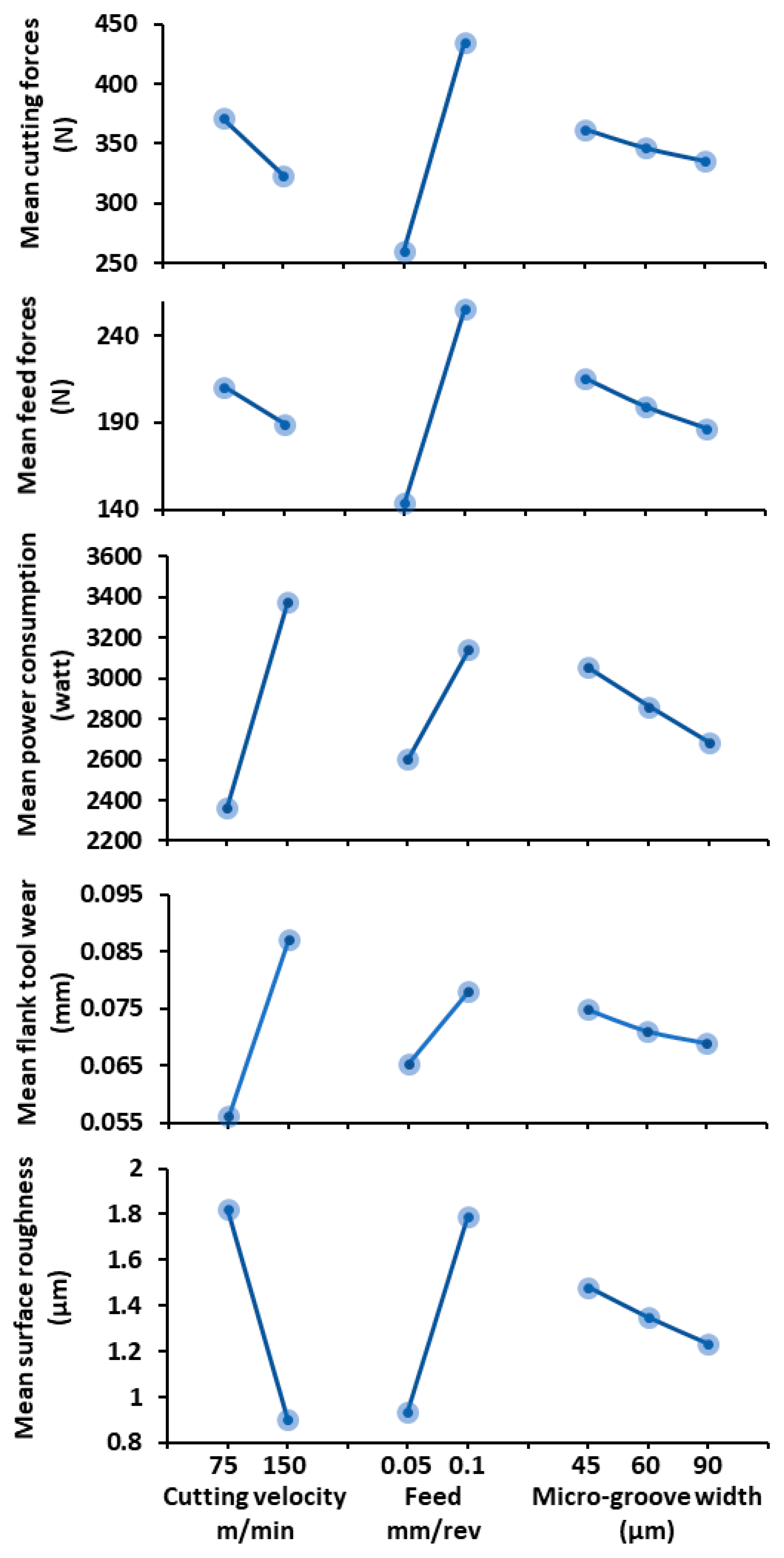
Figure 5 show the measured cutting and feed forces for the conducted experiments. It is known that the forces vary with changes in the cutting speed. This is because of strain hardening or thermal softening of the workpiece material during the machining process. These two reasons (i.e., strain hardening and thermal softening) alter at different cutting velocities. The measured forces indicate that thermal softening is dominated by an increase in cutting speed from 75 m/min to 150 m/min, which causes a decrease in the measured forces. Figure 9 shows a slight decrease in mean cutting and feed forces while increasing the cutting velocity. It is well understood that increasing the feed value will increase the forces. The outcomes shown in Figure 8 further supported the notion that the rise in feed value was correlated with a significant increase in the mean cutting and feed forces. This indicates that the effect of the feed was higher than the effect of other process parameters on the mean cutting and feed forces.
For the cutting conditions of 75 m/min cutting speed and 0.05 feed, all of the different textured cutting tools (i.e., design 1, design 2, and design 3) showed lower cutting forces and feed forces compared to the non-textured cutting tool (see Figure 4 and Figure 5). This is because of the absence of the derivative cutting phenomena associated with using these tools in this cutting condition (see Figure 3). The cutting forces were reduced by 2.5%, 2.9%, and 3% for designs 1, 2, and 3, respectively, but these reductions were modest. For the feed forces, the reductions were 5.5%, 5.7%, and 6% for textured design 1, textured design 2, and textured design 3, respectively. Because of the absence of derivative cutting and the use of the same total width of all micro-grooves throughout all designs, the cutting and feed force results were comparable (same reduction in the contact length). Since the feed force and frictional force had almost the same direction, the reduction in the feed forces was greater than the reduction in the cutting forces for all texture designs. Similarly, all textured cutting tools offered lower forces compared to the non-textured cutting tool at a feed of 0.05 mm/rev and cutting speed of 150 m/min (tests 9, 10, 11, and 12). For the cutting forces, the reductions were minimal: 1.6%, 2%, and 2% for textured designs 1, 2, and 3, respectively. The reductions in the feed forces were 2.4%, 3%, and 3.5% for textured design 1, textured design 2, and textured design 3, respectively. The smaller reduction associated with the textured tools at a higher speed and the same feed of 0.05 mm/rev was due to the shorter chip-tool contact length at a higher speed. According to the previously shown force results at low feed, the reduction in feed and cutting forces associated with using textured cutting tools was up to 6% and 3%, respectively. This is because of the far position of the first micro-groove (at 240 µm from the cutting edge) along with the shorter contact length in the case of a small feed value compared to the higher feed value. In addition, it can be stated that the effect of the micro-groove width is less significant if the micro-groove is located far from the cutting edge (i.e., near the separation point).
The derivative cutting observed when using design 1 was the cause of the higher cutting and feed forces compared to the non-textured cutting tool at a feed of 0.1 mm/rev and cutting velocity of 75 m/min (i.e., test 6). Cutting and feed forces increased by about 11% and 19%, respectively, when using design 1. Similarly, design 2 in the same cutting condition (i.e., test 7) showed higher cutting and feed forces compared to the non-textured cutting tool by 6% and 10.6%, respectively. This was because of the presence of derivative cutting (see test 7 in Figure 3). This phenomenon arises due to the proximity of the initial micro-groove (located at 240 µm from the cutting edge), coupled with the increased contact length observed in situations involving higher feed values, as opposed to lower feed values. The existence of derivative cutting augments the extent of contact between the rake face and the resultant chip. Consequently, this results in escalated cutting and feed forces.
However, the textured tool of design 3 provided lower cutting and feed forces compared to the non-textured tool by 2% and 4%, respectively. This confirms that the absence of severe derivative cutting (see test 8 in Figure 3) can show up the benefits of using textured cutting tools in reducing forces. In addition, it can be noticed that using a narrow micro-groove can eliminate derivative cutting.
For the performance of design 1 at a feed of 0.1 mm/rev and a cutting velocity of 150 m/min, the cutting and feed forces were still higher compared to the non-textured tool by 7% and 13.5%, respectively. These increases in the forces of test 14 (i.e., high cutting velocity and high feed) were lower than the increases in the forces of test 6 (i.e., low cutting velocity and high feed). This was due to the shorter chip-tool contact length associated with a higher cutting velocity. Unlike the performance of design 2 in test 7 (i.e., low cutting velocity and high feed), design 2 showed lower cutting and feed forces in test 15 (i.e., high cutting velocity and high feed) compared to the non-textured tool by 2.5% and 4.3%, respectively. In addition, design 3 provided lower cutting and feed forces in test 16 by 4.5% and 9%, respectively. It can be stated that the effect of the micro-groove width is more significant when the micro-groove is generated close to the main cutting edge (i.e., in the case of high feed). This was seen especially in the different performances of design 2 in test 7 and test 15. The advantages of the textured cutting tool become especially apparent when the micro-groove is applied neither very close to nor very far from the cutting edge. In addition, Figure 9 displays how the mean cutting and feed forces can be reduced by employing a narrower micro-groove.

3.2. Power Consumption

Figure 6 shows the measured power consumption for each machining test. The measured power included all of the power consumed by different parts of the machine, such as the spindle motor power and feed-axis motor. Figure 6 shows that increasing the cutting speed and feed increases power consumption. Figure 9 demonstrates that cutting velocity is the most influential parameter on mean power consumption, followed by feed rate and micro-groove width. For the cutting conditions of 75 m/min cutting velocity and 0.05 mm/rev feed, all of the textured designs consumed less power than the non-textured cutting tool (3% to 5% less). In a similar manner, machining using the textured cutting tools consumed less power compared to the non-textured tool at 150 m/min and 0.05 mm/rev. The reduction in power consumption was 2.3%, 2.6%, and 5.6% for design 1, design 2, and design 3, respectively. In the absence of derivative cutting, machining with textured cutting tools uses less power than machining with a non-textured cutting tool. However, at a cutting velocity of 75 m/min and feed of 0.1 mm/rev, design 1 and design 2 showed higher power consumption (i.e., in the case of complete and partial filling of micro-grooves cavities) compared to the machining using the non-textured tool. The measured power consumption when using design 3 was less than with the non-textured cutting tool by 5.7% at the same cutting condition (i.e., cutting velocity of 75 m/min and feed of 0.1 mm/rev). Furthermore, at a cutting velocity of 150 m/min and feed of 0.1 mm/rev, machining with design 1 showed higher power consumption (i.e., in the case of the presence of derivative cutting) compared to the non-textured tool by 12%. At the same cutting condition, machining with design 2 and design 3 consumed less power compared to machining with the non-textured tool by 4.5% and 9.8%, respectively. The absence of derivative cutting improved power consumption when textured cutting tools were used. Figure 9 shows that decreasing the micro-groove width reduces mean power consumption, reducing the likelihood of derivative cutting.

3.3. Flank Tool Wear

Figure 7 depicts the flank tool wear Vb measurements of the textured and non-textured cutting tools used in the experiments, for the total cutting length of each test of 12.5 m. Maximum flank tool wear is used as a numerical indicator for flank tool wear. It can be seen in Figure 7 and Figure 9 that the cutting velocity has the most significant effect on flank tool wear, followed by the feed and micro-groove width, where increasing the cutting velocity and feed values leads to an increase in flank tool wear.
The textured cutting tools showed better performance on flank tool wear compared to the non-textured tool at 0.05 mm/rev feed when using cutting velocities of 75 m/min and 150 m/min. However, the effect of micro-groove width on mean flank wear was less significant than its effect on forces and power consumption because the generated grooves were located on the rake faces of the utilized textured tools (see Figure 9). This can be found in the enhancement in flank tool wear results when using the textured cutting tools compared to the enhancement observed in power consumption. The range of these improvements was 2–5%. For the cutting conditions of 75 m/min cutting velocity and 0.1 mm/rev feed, design 1 and design 2 provided higher flank tool wear compared to the non-textured cutting tool by 14% and 7.7%, respectively. This is due to the additional forces and heat generated by the derivative cutting phenomenon observed in this condition. However, design 3 showed lower tool wear by 2% compared to the non-textured tool. The flank wear results were in line with the cutting and feed forces presented earlier in Section 3.1.
Similarly, design 2 and design 3 offered less flank tool wear than the non-textured cutting tool at a cutting velocity of 150 m/min and feed of 0.1 mm/rev by 2% and 4%, respectively. These minor improvements were the result of the cutting velocity’s predominance over the flank tool wear across the microgroove width (see Figure 9). On the other hand, in the same cutting conditions, the presence of derivative cutting associated with design 1 showed higher flank tool wear compared to the non-textured tool by 9%. The textured cutting tool with narrow micro-grooves and far position of the first micro-groove reduce the presence of derivative cutting. This leads to lower cutting forces and lower flank tool wear. Furthermore, textured cutting tools play a significant role in capturing and trapping generated debris and abrasive particles during the machining process. By effectively trapping these abrasive particles, the textured cutting tools help mitigate the detrimental effects of scratching on the cutting tool faces, thereby minimizing abrasive tool wear.

3.4. Surface Roughness

The surface roughness of the machined surface Ra was measured after the total cutting length of 12.5 m for each test experiment (see Figure 8). At the cutting condition of 75 m/min cutting velocity and 0.05 feed, all textured cutting tool designs showed better performance on surface roughness compared to the non-textured tool. This is a result of their improved flank tool wear performance under the same cutting conditions. However, the enhancement percentage for all textured cutting tool designs was reduced (2~4%) at the cutting velocity of 150 m/min and 0.05 mm/rev, as shown in Figure 8. On the other hand, design 1 and design 2 provided higher surface roughness compared to the non-textured tool at 75 m/min cutting velocity and 0.1 feed mm/rev by 13% and 9%, respectively. While design 3 showed lower surface roughness at the same cutting condition. For the cutting condition of 150 m/min cutting velocity and 0.1 feed mm/rev, design 2 and design 3 showed lower surface roughness compared to the non-textured cutting tool by 7% and 15%, respectively. While design 1 provided higher surface roughness compared to the non-textured tool similar to its performance at 75 m/min cutting velocity and 0.1 mm/rev feed. It is important to note that the presence or absence of derivative cutting phenomena when employing textured cutting tools is directly correlated with the aforementioned results. It is well known that feed rate and cutting speed have significant effects on surface roughness. Figure 9 depicts their effects via the mean surface roughness at various levels. The ideal cutting condition for reducing surface roughness is to decrease the feed value while increasing the cutting velocity. Due to the lower contact length and cutting forces, higher cutting velocity has a positive impact on surface roughness. In addition, using a lower cutting velocity may lead to the formation of a built-up edge (BUE), which has a negative influence on surface roughness.

3.5. The Interaction Effects of Machining Parameters with Texture Design Parameters

All presented results, including the microscopic images in Figure 3, point to a connection between the machining and texture design parameters that affect the occurrence of derivative cutting. The feed value and the cutting velocity are responsible for determining the chip-tool contact length. In addition, the relative relationship between the contact length and the textured parameters (i.e., micro-groove position and width) plays a dominant role in the presence/absence of the derivative cutting phenomena. The length of contact between the cutting tool’s rake face and the chip is contingent on the machining parameters and the coefficient of friction. This coefficient of friction is inherently associated with the materials of both the workpiece and the cutting tool. Consequently, when employing the same cutting conditions on a different workpiece, varying contact lengths will be obtained. As illustrated in Figure 10, if the micro-grooves are located relatively close to the cutting edge (see the red zone in Figure 10), severe derivative cutting will occur, accompanied by complete and partial filling of the micro-grooves’ cavities. The advantages of using textured cutting tools will be jeopardized as a result. In addition, if the micro-grooves are located relatively far from the cutting edge and near the separation point (see the gray zone in Figure 10), derivative cutting will not occur due to the lower normal stress at this zone (see the microscopical images of the textured tool at tests 2, 3, 4, 10, 11, 12 in Figure 3). However, the textured cutting tool will exhibit lower enhancements in terms of the machining outputs compared to the non-textured tool (see the previous experimental results of textured cutting tools at 0.05 feed with 75 m/min and 150 cutting velocities).
The best scenario for achieving the targeted benefits when using textured tools is to generate narrow micro-grooves starting from the first position, where derivative cutting is eliminated (see the green zone in Figure 10). This position is relatively dependent on the contact length, depending on the utilized machining parameters. In that case, the textured cutting tool showed higher enhancements compared to the non-textured tool (see the previous experimental results of design 3 at 0.1 feed and 75 m/min, and designs 2 and 3 at 0.1 feed and 150 m/min). Thus, to avoid the occurrence of derivative cutting, the machining and texture design parameters should be properly selected.

4. Conclusions

This study investigated the effects of significant texture design parameters (i.e., micro-groove position and width) when cutting AISI 1045 steel using different machining parameters (i.e., cutting velocity and feed). Three different textured cutting tool designs were prepared using the laser texturing technique and utilized in the machining experiments. Sixteen orthogonal cutting tests were conducted using three textured tool designs and non-textured cutting tools at different cutting conditions of cutting velocities of 75 m/min and 150 m/min and feed values of 0.05 mm/rev and 0.1 mm/rev. In addition, the measured machining outputs were forces, power consumption, flank wear, and surface roughness to compare the performance of the utilized cutting tools.
From the obtained microscopical images after the machining tests, there were no marks for the derivative cutting when using textured cutting tool design 3 (i.e., a textured tool with narrow micro-grooves 45 mm) at low feed with low and high cutting velocities, respectively. In addition, when using design 3 at a high feed, there were minor marks for derivative cutting and trapping of the cutting debris at low and high cutting velocities, respectively. It can be stated that the micro-groove with a small width (i.e., design 3) can reduce the occurrence of derivative cutting with complete and partial filling actions. These actions were observed when using design 1 at high feed and with design 2 at high feed and low cutting velocity.
Furthermore, design 3 demonstrated superior performance compared to both the non-textured cutting tool and the other textured tool designs when considering the measured machining outputs. Notably, the utilization of design 3 resulted in reductions of up to 4.5% in cutting forces (test 8), up to 9% in feed forces (test 8), up to 9% in power consumption (test 16), up to 4% in flank tool wear (test 16), and up to 15% in surface roughness (test 16), as compared to the non-textured tool. These findings confirm the advantages of employing textured cutting tools, especially in the absence of severe derivative cutting, which further contributes to the reduction of all studied machining outputs.
Based on the experimental results, it is evident that the relative relationship between the contact length and the textured parameters, specifically the micro-groove position and width, plays a dominant role in determining the presence or absence of the derivative cutting phenomena. This relationship highlights the significance of carefully considering the design and configuration of textured cutting tools. In addition, the optimal scenario for achieving the targeted benefits when using textured tools is to generate narrow micro-grooves starting from the first position, where derivative cutting is eliminated. These findings emphasize the potential benefits and effectiveness of utilizing textured cutting tools. They also provide significant recommendations to cutting tool developers to optimally design textured cutting tools. In addition, they highlight the potential for micro-textured tools to serve as a sustainable option in the machining industry.

Author Contributions

A.S. designed, performed relevant experiments, and wrote the manuscript; H.H. and H.A.K. supervised the experiments and data analysis and reviewed the manuscript. All authors have read and agreed to the published version of the manuscript.

Funding

This study was funded by the Natural Sciences and Engineering Research Council of Canada (NSERC).

Data Availability Statement

All data generated or analyzed during this study are included in this published article.

Conflicts of Interest

The authors declare and confirm no conflict of interest.

References

  1. Khanna, N.; Wadhwa, J.; Pitroda, A.; Shah, P.; Schoop, J.; Sarıkaya, M. Life cycle assessment of environmentally friendly initiatives for sustainable machining: A short review of current knowledge and a case study. Sustain. Mater. Technol. 2022, 32, e00413. [Google Scholar] [CrossRef]
  2. Hughes, J.; Sharman, A.; Ridgway, K. The effect of cutting tool material and edge geometry on tool life and workpiece surface integrity. Proc. Inst. Mech. Eng. Part B J. Eng. Manuf. 2006, 220, 93–107. [Google Scholar] [CrossRef]
  3. Neşeli, S.; Yaldız, S.; Türkeş, E. Optimization of tool geometry parameters for turning operations based on the response surface methodology. Measurement 2011, 44, 580–587. [Google Scholar] [CrossRef]
  4. Ranjan, P.; Hiremath, S.S. Role of textured tool in improving machining performance: A review. J. Manuf. Process. 2019, 43, 47–73. [Google Scholar] [CrossRef]
  5. Hoghoughi, M.; Farahnakain, M.; Elhami, S. Environmental, economical, and machinability based sustainability assessment in hybrid machining process employing tool textures and solid lubricant. Sustain. Mater. Technol. 2022, 34, e00511. [Google Scholar] [CrossRef]
  6. Gajrani, K.K.; Sankar, M.R. State of the art on micro to nano textured cutting tools. Mater. Today Proc. 2017, 4, 3776–3785. [Google Scholar] [CrossRef]
  7. Ma, J.; Duong, N.H.; Chang, S.; Lian, Y.; Deng, J.; Lei, S. Assessment of microgrooved cutting tool in dry machining of AISI 1045 steel. J. Manuf. Sci. Eng. 2015, 137, 031001. [Google Scholar] [CrossRef]
  8. Alagan, N.T.; Zeman, P.; Hoier, P.; Beno, T.; Klement, U. Investigation of micro-textured cutting tools used for face turning of alloy 718 with high-pressure cooling. J. Manuf. Process. 2019, 37, 606–616. [Google Scholar] [CrossRef]
  9. Jianxin, D.; Wenlong, S.; Hui, Z. Design, fabrication and properties of a self-lubricated tool in dry cutting. Int. J. Mach. Tools Manuf. 2009, 49, 66–72. [Google Scholar] [CrossRef]
  10. Xie, J.; Luo, M.; Wu, K.; Yang, L.; Li, D. Experimental study on cutting temperature and cutting force in dry turning of titanium alloy using a non-coated micro-grooved tool. Int. J. Mach. Tools Manuf. 2013, 73, 25–36. [Google Scholar] [CrossRef]
  11. Jesudass Thomas, S.; Kalaichelvan, K. Comparative study of the effect of surface texturing on cutting tool in dry cutting. Mater. Manuf. Process. 2018, 33, 683–694. [Google Scholar] [CrossRef]
  12. Jianxin, D.; Ze, W.; Yunsong, L.; Ting, Q.; Jie, C. Performance of carbide tools with textured rake-face filled with solid lubricants in dry cutting processes. Int. J. Refract. Met. Hard Mater. 2012, 30, 164–172. [Google Scholar] [CrossRef]
  13. Koshy, P.; Tovey, J. Performance of electrical discharge textured cutting tools. CIRP Ann. 2011, 60, 153–156. [Google Scholar] [CrossRef]
  14. Fatima, A.; Mativenga, P.T. A comparative study on cutting performance of rake-flank face structured cutting tool in orthogonal cutting of AISI/SAE 4140. Int. J. Adv. Manuf. Technol. 2015, 78, 2097–2106. [Google Scholar] [CrossRef]
  15. Liu, Y.; Deng, J.; Wu, F.; Duan, R.; Zhang, X.; Hou, Y. Wear resistance of carbide tools with textured flank-face in dry cutting of green alumina ceramics. Wear 2017, 372, 91–103. [Google Scholar] [CrossRef]
  16. Niketh, S.; Samuel, G. Surface texturing for tribology enhancement and its application on drill tool for the sustainable machining of titanium alloy. J. Clean. Prod. 2017, 167, 253–270. [Google Scholar] [CrossRef]
  17. Kümmel, J.; Braun, D.; Gibmeier, J.; Schneider, J.; Greiner, C.; Schulze, V.; Wanner, A. Study on micro texturing of uncoated cemented carbide cutting tools for wear improvement and built-up edge stabilisation. J. Mater. Process. Technol. 2015, 215, 62–70. [Google Scholar] [CrossRef]
  18. Duan, R.; Deng, J.; Ai, X.; Liu, Y.; Chen, H. Experimental assessment of derivative cutting of micro-textured tools in dry cutting of medium carbon steels. Int. J. Adv. Manuf. Technol. 2017, 92, 3531–3540. [Google Scholar] [CrossRef]
  19. Duan, R.; Deng, J.; Lei, S.; Ge, D.; Liu, Y.; Li, X. Effect of derivative cutting on machining performance of micro textured tools. J. Manuf. Process. 2019, 45, 544–556. [Google Scholar] [CrossRef]
  20. Mishra, S.K.; Ghosh, S.; Aravindan, S. Machining performance evaluation of Ti6Al4V alloy with laser textured tools under MQL and nano-MQL environments. J. Manuf. Process. 2020, 53, 174–189. [Google Scholar] [CrossRef]
  21. Sugihara, T.; Kobayashi, R.; Enomoto, T. Direct observations of tribological behavior in cutting with textured cutting tools. Int. J. Mach. Tools Manuf. 2021, 168, 103726. [Google Scholar] [CrossRef]
  22. Wu, Z.; Bao, H.; Liu, L.; Xing, Y.; Huang, P.; Zhao, G. Numerical investigation of the performance of micro-textured cutting tools in cutting of Ti-6Al-4V alloys. Int. J. Adv. Manuf. Technol. 2020, 108, 463–474. [Google Scholar] [CrossRef]
  23. Kishawy, H.A.; Salem, A.; Hegab, H.; Hosseini, A.; Balazinski, M. Micro-textured cutting tools: Phenomenological analysis and design recommendations. CIRP Ann. 2021, 70, 65–68. [Google Scholar] [CrossRef]
  24. Shah, P.; Khanna, N.; Maruda, R.W.; Gupta, M.K.; Krolczyk, G.M. Life cycle assessment to establish sustainable cutting fluid strategy for drilling Ti-6Al-4V. Sustain. Mater. Technol. 2021, 30, e00337. [Google Scholar] [CrossRef]
  25. Khanna, N.; Shah, P.; Sarikaya, M.; Pusavec, F. Energy consumption and ecological analysis of sustainable and conventional cutting fluid strategies in machining 15–5 PHSS. Sustain. Mater. Technol. 2022, 32, e00416. [Google Scholar] [CrossRef]
  26. Zerti, O.; Yallese, M.A.; Belhadi, S.; Bouzid, L. Taguchi design of experiments for optimization and modeling of surface roughness when dry turning X210Cr12 steel. In Applied Mechanics, Behavior of Materials, and Engineering Systems; Springer: Berlin/Heidelberg, Germany, 2017; pp. 275–288. [Google Scholar]
  27. Iqbal, S.; Mativenga, P.; Sheikh, M. A comparative study of the tool–chip contact length in turning of two engineering alloys for a wide range of cutting speeds. Int. J. Adv. Manuf. Technol. 2009, 42, 30–40. [Google Scholar] [CrossRef]
  28. Iqbal, S.; Mativenga, P.; Sheikh, M. Characterization of machining of AISI 1045 steel over a wide range of cutting speeds. Part 1: Investigation of contact phenomena. Proc. Inst. Mech. Eng. Part B J. Eng. Manuf. 2007, 221, 909–916. [Google Scholar] [CrossRef]
Figure 1. (a) A schematic of the tube turning experiments using different textured designs, and (b) experimentation setup.
Metals 13 01587 g001
Figure 2. Two-dimensional microscopical images for the three micro-textured designs.
Metals 13 01587 g002
Figure 3. Two-dimensional microscopical images of the cutting tools rake faces of the used cutting inserts for 16 cutting tests.
Metals 13 01587 g003
Figure 4. The measured cutting forces of the conducted machining tests using non-textured and textured cutting.
Metals 13 01587 g004
Figure 5. The measured feed forces of the conducted machining tests using non-textured and textured cutting tools.
Metals 13 01587 g005
Figure 6. The measured power consumption of machining tests performed with non-textured and textured cutting tools.
Metals 13 01587 g006
Figure 7. The measured flank tool wear results when using non-textured and textured cutting tools.
Metals 13 01587 g007
Figure 8. The measured surface roughness Ra results for the machining experiments conducted with non-textured and textured cutting tools.
Metals 13 01587 g008
Figure 9. The mean values of the measured machining outputs associated with the machining parameters and micro-groove widths.
Metals 13 01587 g009
Figure 10. Schematic diagram of the relative effect of machining parameters and texture dimension parameters.
Metals 13 01587 g010
Table 1. The experimentation plan of the machining tests at different cutting velocities and feeds with different tool designs and the total cutting length of each test of 12.5 m.
Test#Cutting Velocity (m/min)Feed (mm/rev)Micro-Groove Width (µm)
1750.050
(Non-textured tool)
2750.0590
(Textured tool-design 1)
3750.0560
(Textured tool-design 2)
4750.0545
(Textured tool-design 3)
5750.10
(Non-textured tool)
6750.190
(Textured tool-design 1)
7750.160
(Textured tool-design 2)
8750.145
(Textured tool-design 3)
91500.050
(Non-textured tool)
101500.0590
(Textured tool-design 1)
111500.0560
(Textured tool-design 2)
121500.0545
(Textured tool-design 3)
131500.10
(Non-textured tool)
141500.190
(Textured tool-design 1)
151500.160
(Textured tool-design 2)
161500.145
(Textured tool-design 3)
Disclaimer/Publisher’s Note: The statements, opinions and data contained in all publications are solely those of the individual author(s) and contributor(s) and not of MDPI and/or the editor(s). MDPI and/or the editor(s) disclaim responsibility for any injury to people or property resulting from any ideas, methods, instructions or products referred to in the content.

