Abstract
The present work proposes a suitable approach for predicting ductile fracture in a new joining process by plastic deformation called hole hemming. This process creates a combined form- and force-fit joint and enables the joining of lightweight materials with varying formability without requiring heating or auxiliary elements. In this process, the joinability of materials is limited by the occurrence of fracture in the outer sheet, highlighting the crucial need to accurately predict its damage during the process design phase. In this study, five different fracture criteria, including the McClintock, Rice–Tracey, Normalized Cockroft–Latham, and Brozzo and Modified Mohr–Coulomb (MMC) criteria, are examined during the joining of a challenging combination of lightweight materials (aluminum AA6082-T4 and magnesium AZ31). These criteria are calibrated by a hybrid experimental–numerical method using three tests with distinct stress states. These criteria are then implemented into the finite element model of the hole hemming process, utilizing an appropriate user subroutine. The results show that the flange edge of the outer sheet is the most prone region to fracture during the joining process, and a criterion must be able to model the fracture behavior of the material from uniaxial tension to shear to accurately predict fracture in this area. Among the examined criteria, only the MMC criterion was capable of such modeling and accurately predicted the critical displacement of the punch in the hemming stage with a negligible error (about 1%). On the other hand, the prediction accuracy of the other criteria varied significantly depending on the calibration test, resulting in errors ranging from 8.6% to 75.5%. The error of 8.6% was achieved with the Normalized Cockroft–Latham criterion calibrated by a uniaxial tension test. Thus, based on the results, the MMC criterion is recommended for ductile fracture prediction in the hole hemming process, offering valuable insights to assist in process design.
1. Introduction
Within the automotive industry, an escalating emphasis is placed on decreasing the weight of body structures, aiming to enhance vehicle performance and fuel efficiency for economic and ecological purposes. However, ensuring passenger safety and comfort remains a paramount concern, often leading to an upsurge in the weight of automotive structures. In response to these demands, contemporary vehicle manufacturers adopt a design strategy termed “multi-material design.” This approach entails integrating lightweight materials like advanced high-strength steel (AHSS), aluminum alloys, magnesium alloys, and composites [1]. By combining these materials in a strategic manner, engineers can create a structure that is both lightweight and strong, while also meeting safety and comfort standards [2]. This approach allows for improved fuel efficiency and performance, while also addressing concerns related to passenger safety and comfort [3,4].
Possessing a density of 1.74 g·cm−3, magnesium emerges as the most lightweight among structural metals, exhibiting a weight that surpasses aluminum (density of 2.7 g·cm−3) by 35% and is approximately four times lighter than steel (density of 7.86 g·cm−3). Magnesium showcases superior noise and vibration attributes in comparison to aluminum, coupled with heightened formability at elevated temperatures [5]. When employed strategically, magnesium holds the potential for achieving even greater mass reduction than aluminum alloys. Furthermore, it features a more specific stiffness than numerous polymeric materials and composites, thereby enhancing its capacity for mass reduction [3]. When combined with the advantages of aluminum alloys, such as their exceptional strength, formability, corrosion resistance, thermal conductivity, and recyclability, structures made of aluminum and magnesium alloys offer a compelling solution for industries seeking lightweight, durable, and high-performance materials [6].
The combined properties enable the creation of structures that enhance fuel efficiency, improve performance, and contribute to sustainability efforts. However, joining aluminum and magnesium poses several challenges due to their inherent differences in properties [7]. One significant difficulty lies in the formation of brittle intermetallic compounds when aluminum and magnesium come into contact during welding. These intermetallic compounds can weaken the joint and compromise its integrity [8]. Moreover, the significant difference in melting points between aluminum and magnesium further complicates the joining process, as they require different temperature ranges for effective bonding [9]. Additionally, the reactivity of magnesium with oxygen and moisture can lead to the formation of oxide layers on the surface, hindering proper bonding [10]. Furthermore, the difference in thermal expansion coefficients between aluminum and magnesium can cause residual stresses and distortion in the joint. To address these challenges, joining techniques by plastic deformation have been explored as potential solutions [1,11]. However, the low ductility of magnesium alloys at room temperature poses a limitation, as it may lead to fracture when excessive deformation is required to create a mechanical interlock during a joining process, such as clinching [12] and self-piercing riveting (SPR) [13]. Neugebauer et al. [14] created a dieless clinching technique with heat assistance to enhance the formability of magnesium alloys. By heating the flat anvil to temperatures exceeding 220 °C, the process facilitated the formation of joints between magnesium and aluminum sheets, devoid of any cracks. Li et al. [15] introduced a hybrid joining technique called friction self-piercing riveting (F-SPR) to address the joining of low-ductility materials. This innovative method combines the mechanical joining mechanism of SPR with the solid-state joining mechanism of friction stir spot welding (FSSW). In the F-SPR process, the rivet rotates at high speed during the riveting process, enabling the effective joining of these challenging materials. By utilizing the F-SPR process, the rivetability of magnesium alloys could be significantly enhanced, resulting in a substantial increase in joint strength when compared to the traditional SPR process. However, introducing heat into the joining process can exacerbate the aforementioned challenges, while incorporating a rivet can contribute to added weight in the joint, contradicting the primary objective of utilizing magnesium for its lightweight properties.
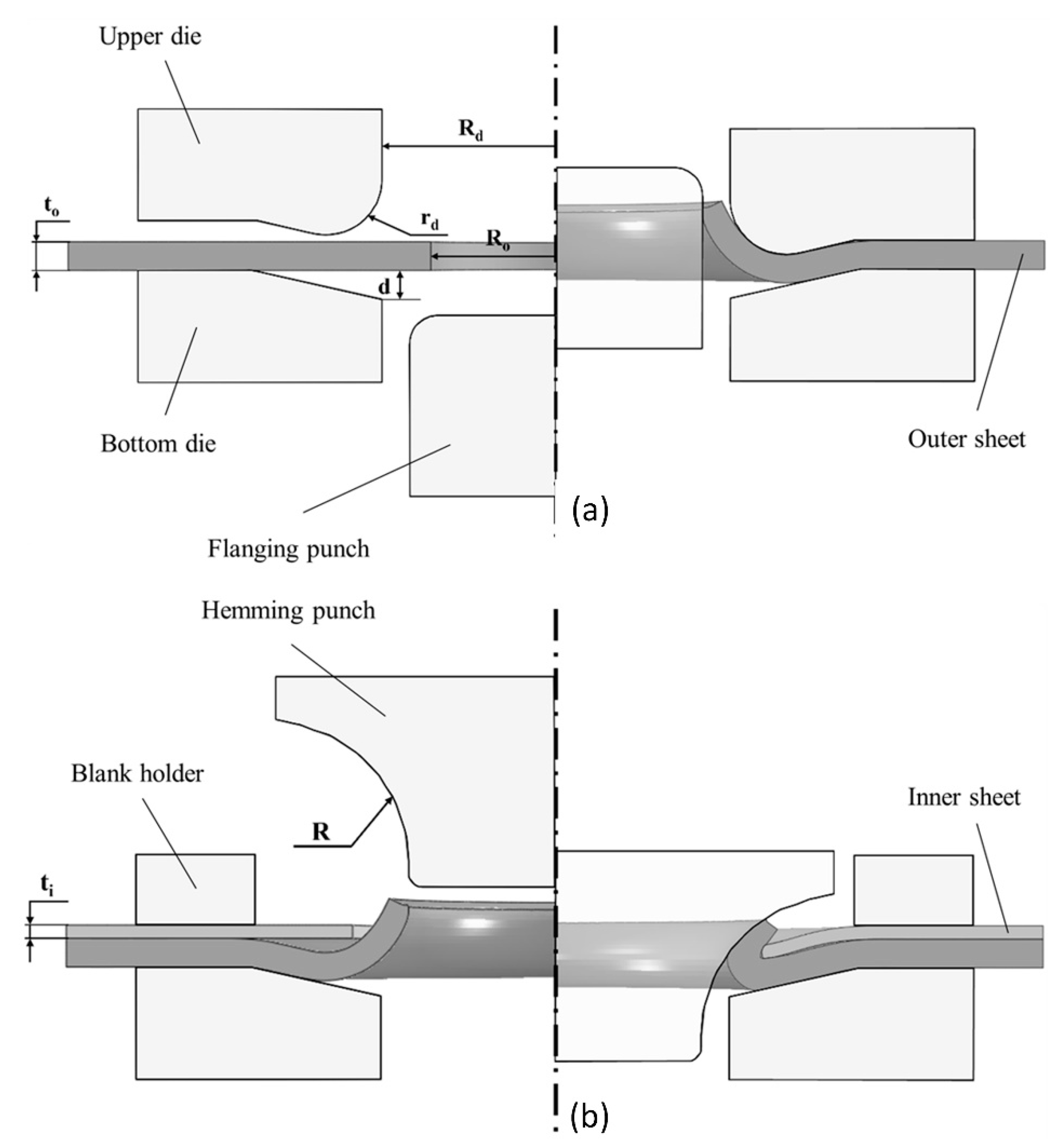
Recently, Kasaei and da Silva [16] established a novel joining process by plastic deformation, named hole hemming, for joining dissimilar materials with very different mechanical properties (see Figure 1). In this joining process, it is necessary for only one of the sheets to possess adequate ductility, eliminating the requirement for heating or the use of supplementary elements like rivets. Additionally, in hole-hemmed (HH) joints, not only is there no increase in weight, but the weight of the joints is actually reduced due to the presence of holes required for creating the mechanical interlock. This process has been successfully tested for joining aluminum AA6082-T4 to magnesium AZ31 sheets, which exhibit very different formability limits [17]. The joints were capable of withstanding a load of 2.9 kN during single-lap shear tests, demonstrating a gradual failure mechanism primarily attributed to hole bearing. This process was also combined with adhesive bonding, called boned-hole hemming, to enhance the mechanical performance of HH joints [18,19]. The bonded-hole hemmed (BHH) joints exhibited a notable strength improvement compared to the HH joint, achieving a maximum strength of at least 11 kN and up to 3.8 times greater strength.

Figure 1.
Schematic illustration of the hole hemming stages along with required punches and dies: (a) hole flanging stage and (b) hemming stage.
The main challenge that limits the process window of the hole hemming process for joining aluminum to magnesium is the possibility of fracture in the aluminum sheet [17]. It is worth noting that the magnesium sheet undergoes only negligible plastic deformation and is much less susceptible to fracture compared to the aluminum sheet. As a result, it is essential to carefully design the process parameters to mitigate the risk of fracture in the aluminum sheet. Achieving this requires accurate modeling of the fracture behavior of the material, which can be employed in finite element simulations to provide valuable insights and aid in the process design.
Under these circumstances, the present study focuses on modeling ductile fracture in the hole hemming process of the aluminum AA6082-T4 and magnesium AZ31 sheets. To achieve this objective, the fracture behavior of the aluminum sheet is characterized by conducting three tests that replicate distinctive loading states. Subsequently, four different fracture criteria are calibrated using these tests through a hybrid experimental–numerical method. These criteria are then implemented into the finite element model of the hole hemming process using an appropriate user subroutine. The predictions of these criteria are compared based on factors such as damage distribution, damage evolution, and critical displacement, taking into account the experimental results. Finally, the most accurate criterion is identified, along with its proper calibration test.
2. Experimental Tests
This study was carried out on the AA6082-T4 aluminum alloy and laboratory-produced ECO-AZ31 magnesium alloy with thicknesses of 2 mm and 0.85 mm, respectively. This section provides a description of the experimental procedures employed in this study.
2.1. Material Properties
To evaluate mechanical properties and plasticity characteristics, uniaxial tension tests were conducted in accordance with ASTM E8 standards using an INSTRON 3367 machine (INSTRON, Norwood, MS, USA) with a test speed of 1 mm/min. Since the ECO-AZ31 sheets were extruded to a width of 100 mm, subsize specimens were prepared. To investigate material anisotropy, specimens were taken from three different orientations: 0, 45, and 90 degrees relative to the rolling or extrusion direction. Displacement of the gauge section, along with major and minor strains, was obtained using digital image correlation (DIC) software GOM 2021 (GOM Metrology, Braunschweig, Germany). Recordings were made with a Canon EOS M5 camera fitted with a Canon EF m 18–55 mm F/3.5–5.6 lens (Canon, Tokyo, Japan), capturing imagery at a frame rate of 25 fps. A summary of the mechanical properties obtained from the uniaxial tension tests is presented in Table 1.

Table 1.
Mechanical properties of the AA 6082-T4 and AZ31 sheets.
The strain hardening behavior of the AZ31 alloy was modeled by the Hollomon law, given by the equation:
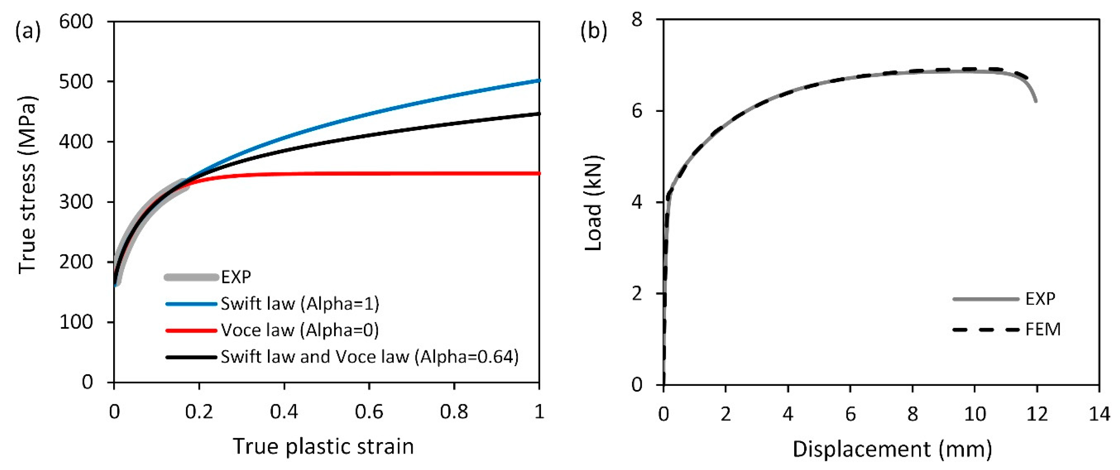
Here, represents the strength coefficient, and denotes the hardening exponent. On the other hand, for the AA6082-T4 alloy, the mixed Swift–Voce hardening law was employed to achieve a more precise post-necking behavior (see Figure 2). The equation is as follows:
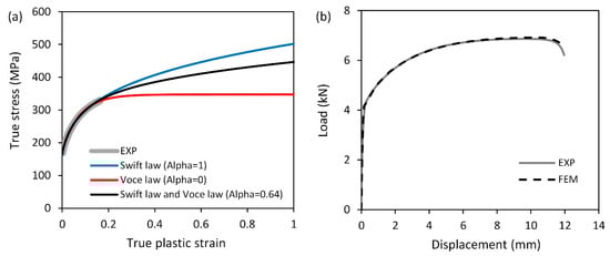
Figure 2.
(a) Stress–strain curve of the AA 6082-T4 sheet modeled based on the Swift, Voce, and mixed Swift–Voce hardening laws, (b) comparison of the numerical load–displacement curve obtained based on the mixed Swift–Voce hardening law with the experimental one.
In this equation, the strength coefficient and hardening exponent of the Swift law are denoted by and , respectively. , , and are parameters characterizing the Voce law. The term represents the pre-strain, and denotes the weighting factor. The Swift and Voce parameters were obtained by fitting them to the experimental true stress plastic strain curve (refer to Figure 2a). Following this, the weighting factor was determined through a reverse approach involving finite element simulations of the uniaxial tension test. The simulations were conducted iteratively until a satisfactory correlation was achieved between the experimental and numerical load–displacement curves, as shown in Figure 2b. The parameters of the strain-hardening laws obtained for the materials are listed in Table 2.
Table 2.
Parameters of the hardening laws obtained for the AA 6082-T4 and AZ31 sheets.
The onset of plastic deformation was defined using the Hill 1948 anisotropic yield criterion. It is represented by the following equation:
where represents the stress components, and , , , , , and are parameters that describe the material’s anisotropy. The values of these parameters can be calculated based on the Lankford coefficients , , and , assuming the associated flow rule in the plane stress state. The equations to calculate the parameters are as follows [20]:
The values of the Hill 1948 yield criterion parameters for the AA 6082-T4 and AZ31 sheets are provided in Table 3.
Table 3.
Hill 1948 parameters obtained for the AA 6082-T4 and AZ31 sheets.
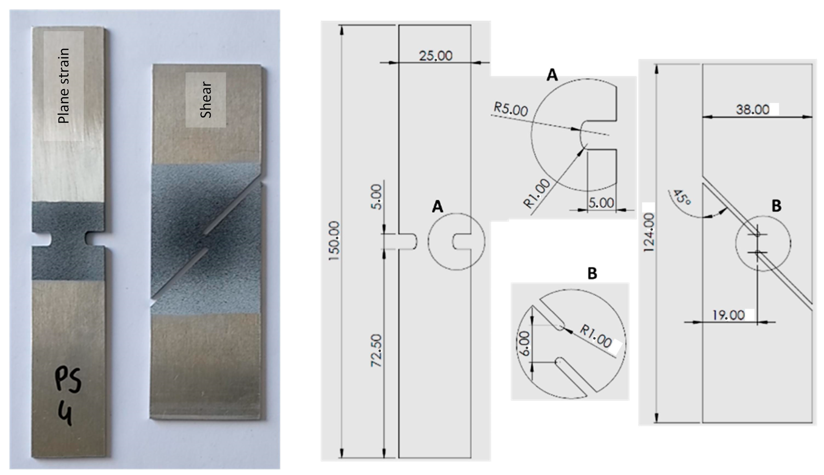
Two additional tension tests with different geometries were conducted to determine the fracture behavior under distinct loading states, including the plane strain and shear tension states (see Figure 3). Specimens were fabricated from the supplied sheets along the rolling or extrusion direction using a CNC milling machine. Subsequently, these specimens were subjected to testing on the INSTRON 3367 at a constant speed of 1 mm/min. Similar to the uniaxial tension tests, the DIC system was used to measure the deformation of the specimens. The force–displacement curve and fracture displacement were extracted to calibrate fracture criteria under different stress states using the hybrid experimental–numerical approach.
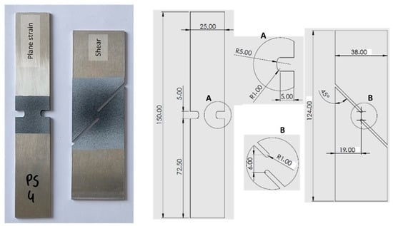
Figure 3.
Plane strain and shear tension specimens (unit: mm).
2.2. Hole Hemming
The hole hemming process involves a two-stage operation to join two sheets. Initially, the hole in the outer sheet is flanged, followed by bending the flange over the hole in the inner sheet (refer to Figure 1). This creates a joint that combines both form and force fits. It is important for the sheets to be concentric while having different radii. The outer sheet, with a smaller radius (), requires sufficient formability to prevent fracture, while the inner sheet with a larger radius (), does not face such limitations. As a result, in this work, the AA6082-T4 aluminum and AZ31 magnesium were chosen as the outer and inner sheets, respectively. In [17], different hole radii for the inner and outer sheets were examined, and to achieve the ideal mechanical lock, hole radii of 14.5 mm and 8.5 mm were proposed for the inner and outer sheets, respectively. These recommended values were used in the current study.
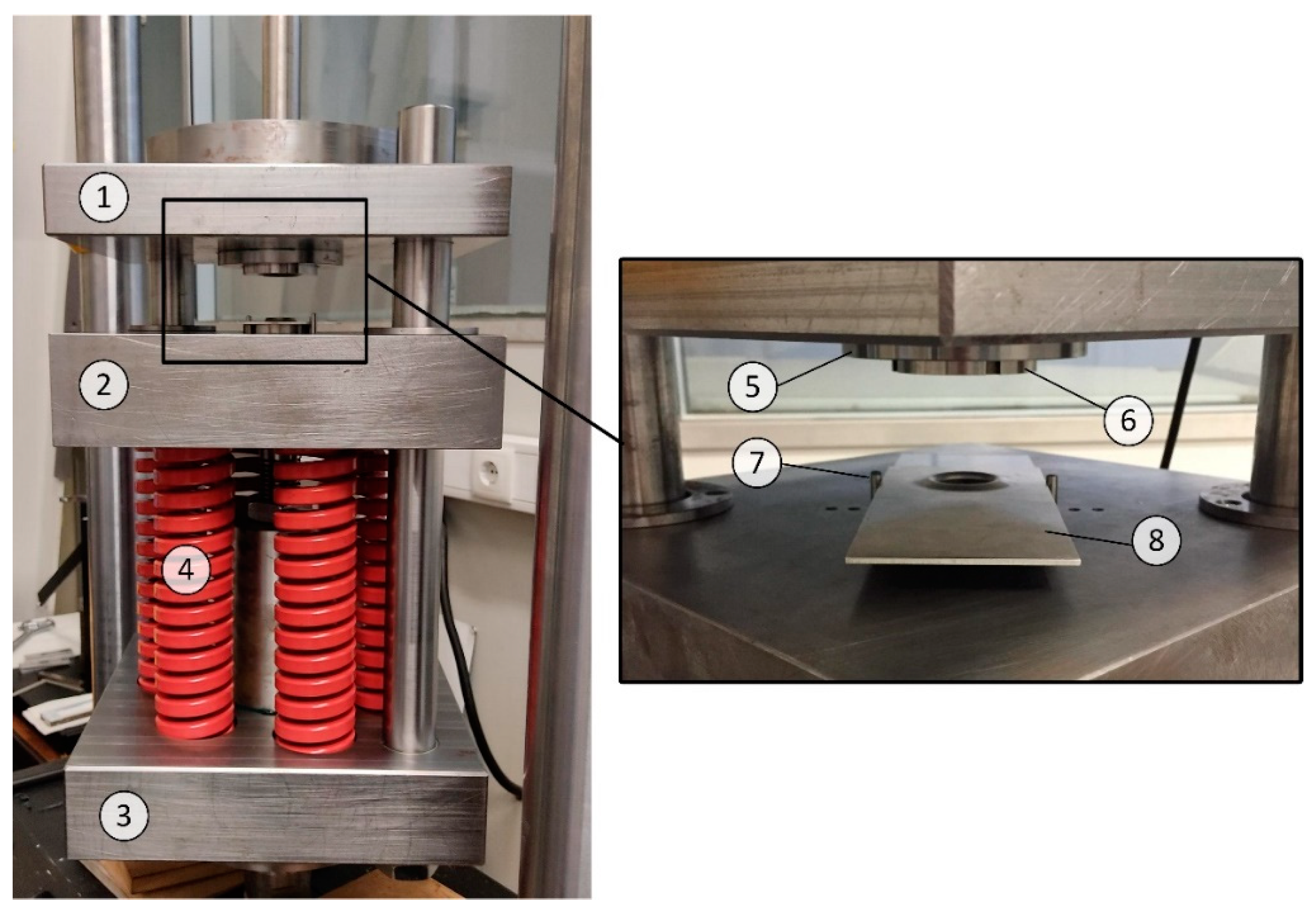
A specific flexible tool designed by the authors was used to carry out the hole hemming experiments in the laboratory [21]. Figure 4 illustrates the hole hemming tool employed in the designed experiments. The tool contains active components (punches and dies), passive components (die holder, punch holder, height adjuster, die holder, and middle plate), and structural components (upper plate, springs, bottom plate). During the process, the active components come into direct contact with the sheets, whereas the passive components provide support to the active components. The structural components, on the other hand, support and accommodate both the active and passive components.

Figure 4.
Hole hemming tool. Upper plate (1), middle plate (2), bottom plate (3), springs (4), die holder (5), die (6), alignment pins (7), and specimen (8).
The tool was mounted on an INSTRON 8801 servo-hydraulic testing machine (INSTRON, Norwood, MS, USA) with a maximum load capacity of 100 kN. The hole flanging and hemming procedures were executed at a speed of 4 mm/min, with respective maximum forces of about 55 kN and 70 kN. Figure 4 demonstrates the correct positioning of the specimen using alignment pins. To achieve a uniform and concentric interlock, it is crucial for the holes in the specimens to be concentric with the center of the die and punch. Thus, a tolerance of 0.05 mm on the concentricity of the holes was considered. The tool components designed in [17,21] were utilized in the experiments. The values of the most important geometric parameters of the specimens and the tool shown in Figure 1 are listed in Table 4.
Table 4.
Specifications of the hole hemming experiments.
3. Finite Element Simulation
3.1. Tension Tests
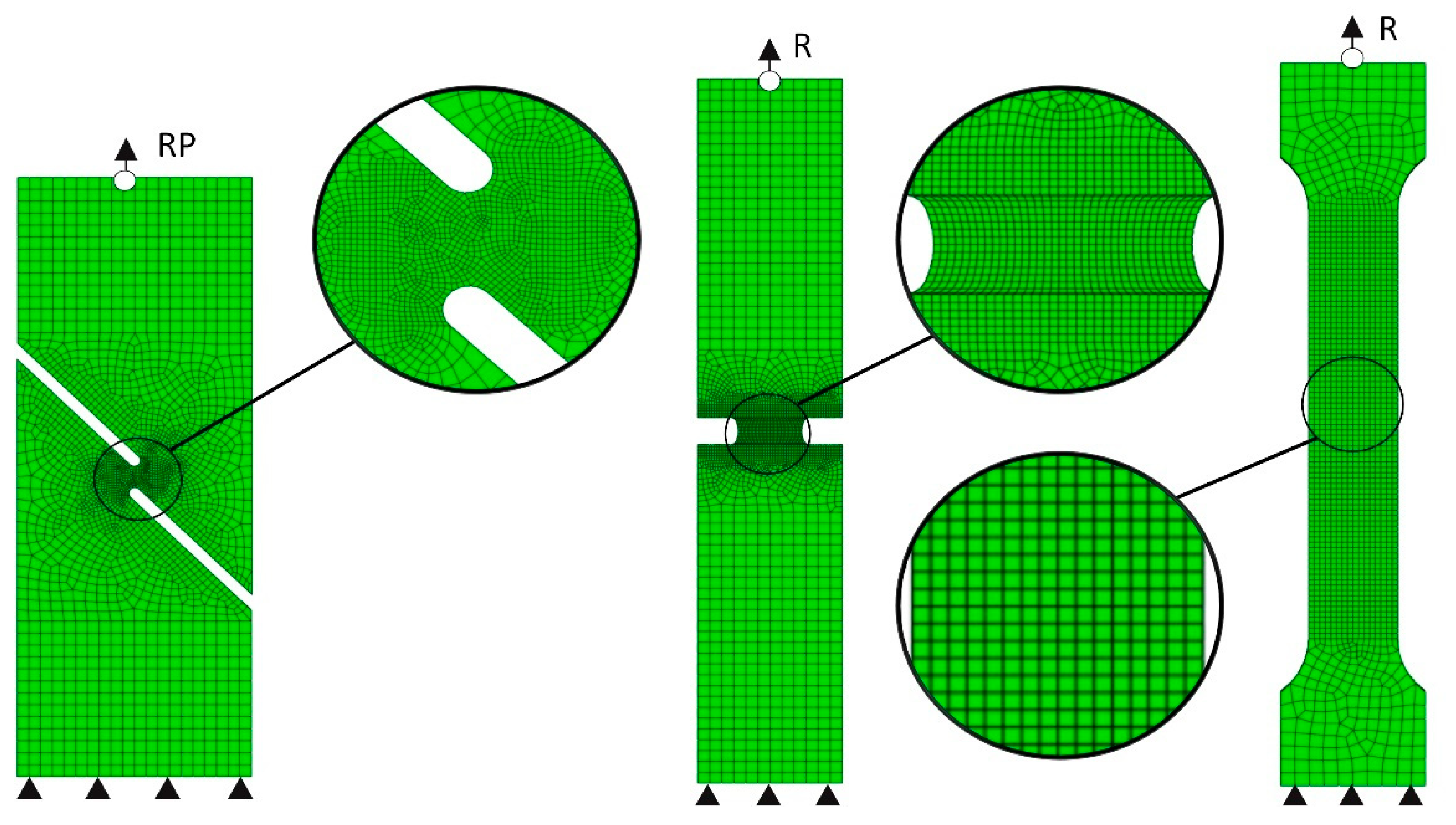
In order to determine the critical damage value for ductile fracture criteria, it is necessary to obtain the equivalent plastic strain at the onset of fracture and to capture the history of stress triaxiality () and normalized Lode angle parameter () during the tension tests. To achieve this, finite element (FE) simulations of the tests were carried out utilizing the Abaqus software 2017 (Dassault Systèmes, Vélizy-Villacoublay, France). Figure 5 shows the FE models of the uniaxial, plane strain, and shear tension tests. The specimens underwent meshing using 3D solid elements (C3D8R) with a dimension of 0.4 mm for the uniaxial tension and plane strain tests. For the shear tension test, which encompassed a relatively small critical area, a reduced element size of 0.25 mm was employed. In order to reduce the computational time, larger elements were utilized outside the critical area of all the specimens. Eight elements were taken into account through the thickness. One side of the specimens was fixed, while the displacement was imposed on the other side.

Figure 5.
Finite element models of the shear, plane strain, and uniaxial tension tests (from left to right).
The material properties, strain hardening, and yielding behavior were defined according to the description provided in Section 2. To enhance computational efficiency, a dynamic explicit solver with a time scaling technique was utilized. The ratio of kinetic energy to internal energy was checked throughout the FE simulation to ensure it remained negligible. Furthermore, variables such as damage indicators, stress triaxiality and normalized Lode angle parameter were incorporated into the FE models using a user subroutine called VUSDFLD.
3.2. Hole Hemming
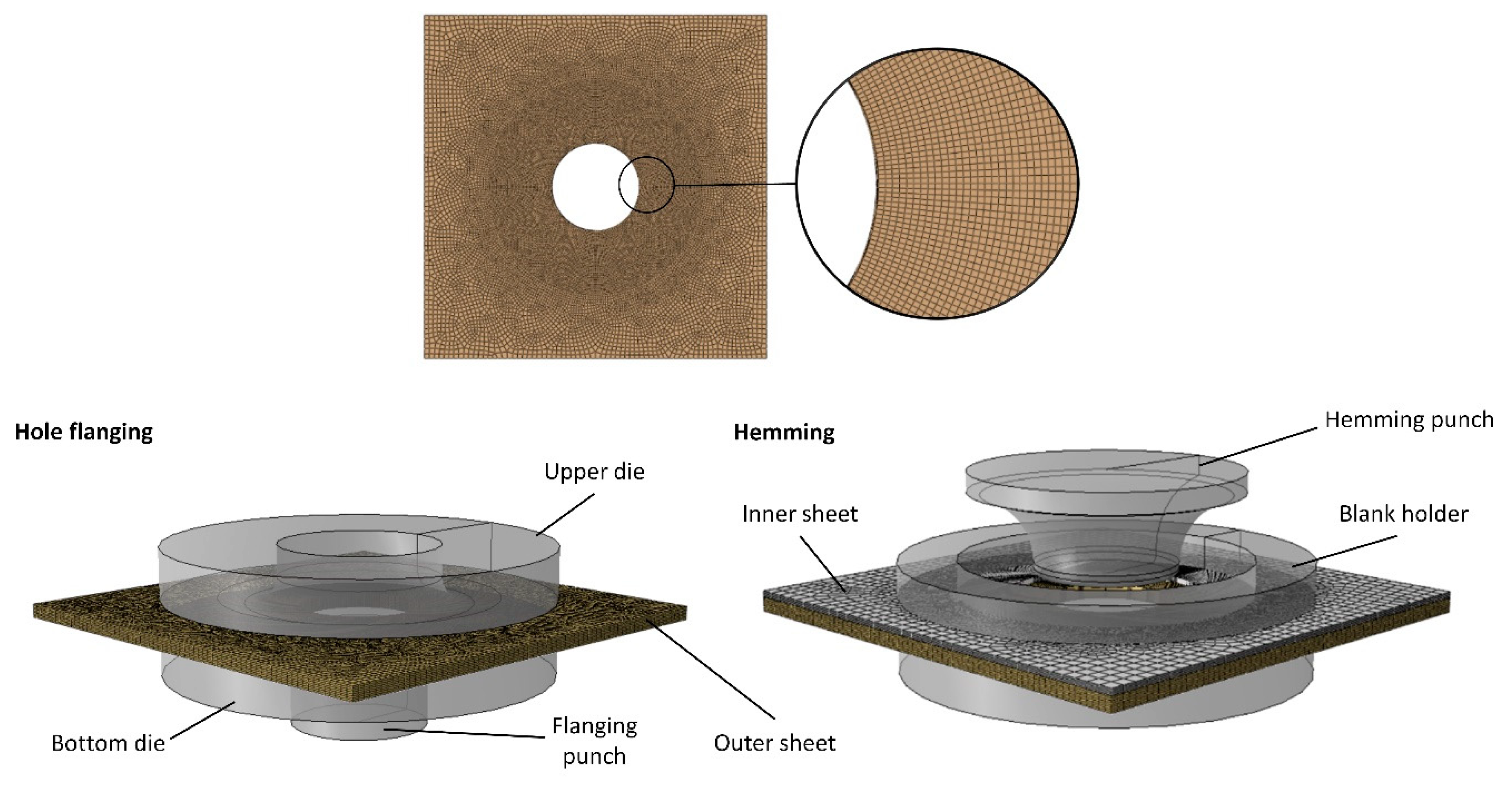
The hole hemming process was simulated using Abaqus 2017/explicit (Dassault Systèmes, Vélizy-Villacoublay, France). The flanging and hemming punches, as well as the bottom and upper dies and blank holder, were modeled as rigid bodies employing analytical models. The sheets were represented using C3D8R solid elements, with eight elements spanning the thickness for the AA6082-T4 sheet and five elements for the AZ31 sheet, taking into account their respective thicknesses. In the regions near the hole sheet edges where higher plastic deformations occur, a reduced element size of 0.2 mm was utilized. Frictional interactions between the punches, dies, and sheets were characterized by employing a penalty-based contact model [22], incorporating the Coulomb law with a coefficient of 0.08. The simulation consisted of three steps: applying displacement to the upper die, followed by the flanging punch, and then the hemming punch. The calibrated ductile fracture criteria specific to the AA6082-T4 were separately implemented in the developed user subroutine (VUSDFLD) to examine the damage evolution and forecast fracture during the joining process. The element deletion technique was employed to simulate crack initiation and crack propagation. The FE model of the hole flanging and hemming stages, along with the mesh pattern of the outer sheet, can be observed in Figure 6.

Figure 6.
Finite element model of the hole flanging and hemming stages.
4. Ductile Fracture Modelling
The ductile fracture criteria establish a correlation between the increments of equivalent plastic strain and the damage indicator, utilizing a suitable weighting function. This correlation can be formulated as follows:
Here, represents the weighting function, denotes the damage indicator, and corresponds to the equivalent plastic strain. Fractures in sheet metals can be addressed through two distinct modeling strategies. The first strategy involves considering the influence of damage induced during plastic deformation on the overall plastic behavior of the sheet metals. Models that adopt this approach are referred to as coupled models [23]. In contrast, the second strategy assumes that the plastic behavior of the sheet is independent of the damage that occurs during deformation. Fracture models based on this approach are known as uncoupled models [24].
Uncoupled models are often favored in industrial applications due to their simplicity and ease of calibration and implementation in numerical simulations. As a result, several weighting functions have been developed based on empirical observations, incorporating various macroscopic variables, such as hydrostatic stress , equivalent stress , maximum principal stress , stress triaxiality and normalized Lode angle parameter , that replicate the loading state. It should be noted that and are defined as follows [25]:
where represents the third deviatoric stress invariant, and ξ denotes the normalized third deviatoric stress invariant. Consequently, these fracture criteria are often referred to as phenomenological models in the literature. In this work, five ductile fracture criteria with distinct weighting functions were considered, including McClintock, Rice–Tracey, Normalized Cockroft–Latham, Brozzo, and Modified Mohr–Coulomb (MMC), which are, respectively, defined as follows [25]:
here, represents the damage indicator for each criterion so that ductile fracture is forecasted as the damage indicator reaches its critical value (hereinafter referred to as ‘single-constant criteria’). Additionally, the MMC criterion (Equation (10)) includes the parameters and , which represent the strain-hardening behavior, as well as three material constants denoted as , , and . While single-constant criteria may have fewer capabilities compared to multi-constant criteria, they are often preferred in designing manufacturing processes due to their simplicity [26,27,28]. Furthermore, each single-constant criterion can offer accurate results for a specific fracture mode. In line with this, Martins et al. [29] characterized fracture loci in metal forming through the consideration of various single-constant criteria, such as McClintock and Normalized Cockroft–Latham criteria.
5. Results and Discussion
5.1. Fracture Envelope
To predict fractures, it is essential to initially determine the critical damage value for the McClintock, Rice–Tracey, Normalized Cockroft–Latham, and Brozzo criteria and the material constants for the MMC criterion through a suitable calibration procedure. In the case of the MMC criterion, the critical damage value is always equal to one. The critical damage value can be determined based on a single test. However, in this study, three calibration tests were conducted to examine their impact on the prediction accuracy of the criteria. On the other hand, all the tests must be utilized simultaneously to determine the three constants of the MMC criterion.
The hybrid numerical and experimental calibration procedure consists of three steps. Firstly, the fracture displacement is identified for the uniaxial, plane strain, and shear tension tests in experimental tests. Secondly, the history of and with respect to is extracted from the element displaying the highest equivalent plastic strain (referred to as the critical element) in the FE simulations of the tension tests. It includes from the beginning of the test until the displacement reaches the fracture displacement. Finally, the critical damage value is determined by integrating the damage weighting functions, as defined in Equations (9)–(12), using the data obtained in the previous step. Additionally, the constants of the MMC criterion are obtained by fitting its 3D fracture envelope to the calibration points derived from the tension tests.
The validity of the FE models plays a critical role in the effectiveness of the hybrid calibration procedure. As a result, the load–displacement curves obtained from experimental tests and those obtained from numerical simulations for the plane strain and shear tests were compared in Figure 7. The numerical and experimental curves exhibit close agreement, indicating the validity and reliability of the FE models in accurately representing the mechanical behavior of the material.
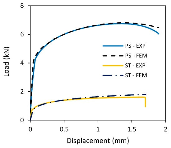
Figure 7.
Comparison of the finite element-predicted and experimental force–displacement curves for the plane strain and shear tension tests.
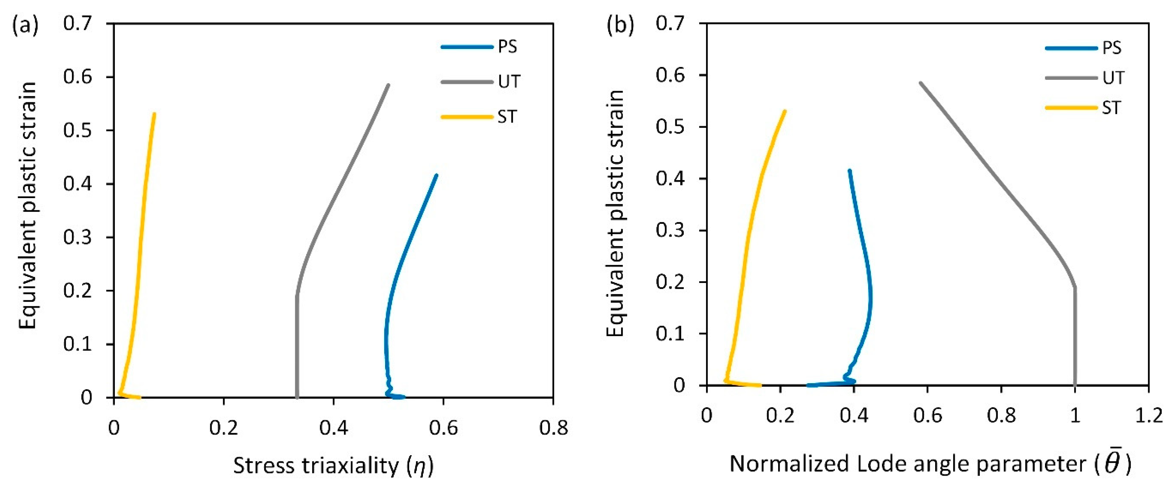
Figure 8 illustrates the history of the stress triaxiality and the normalized Lode angle parameter with respect to the equivalent plastic strain in the critical element. The finite element predicted fracture strains for the uniaxial tension, plane strain tension, and in-plane shear tension tests are 0.58, 0.42, and 0.53, respectively.
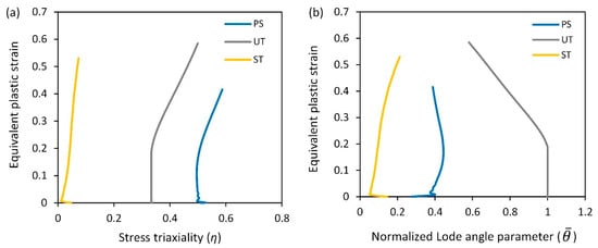
Figure 8.
Evolution of stress triaxiality (a) and normalized Lode angle parameter (b) with equivalent plastic strain during the tension tests for the AA6082-T4 sheet.
As seen, the stress state undergoes variation during these formability tests, exhibiting necking prior to fracture occurrence. Consequently, the loading paths deviate from the anticipated stress states, transitioning towards a plane strain condition dominated by necking. Therefore, the stress triaxiality and the normalized Lode angle parameter were averaged for the calibration of the criteria as follows:
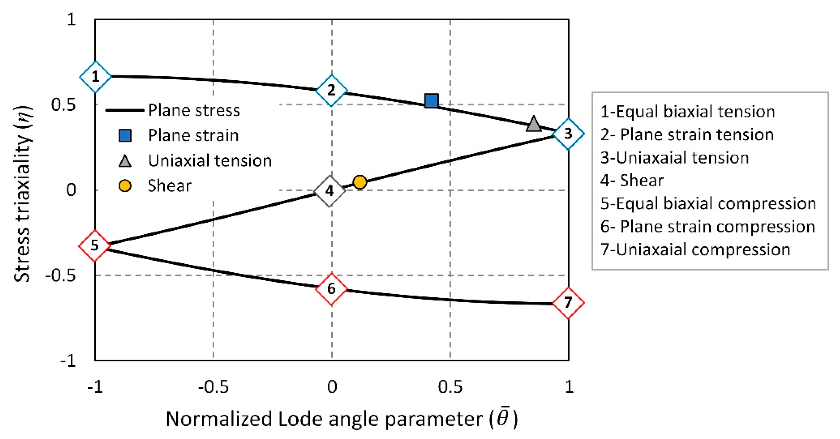
To assess the validity of the obtained stress states, they were plotted in the space of and as shown in Figure 9. Under the plane stress condition, and are not independent parameters but rather correlated with each other, according to Equation (16) [30].
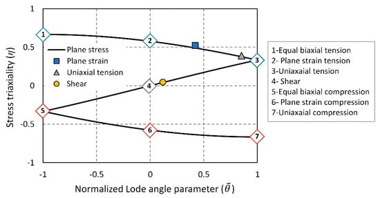
Figure 9.
Average stress triaxiality and normalized Lode angle parameter calculated for the tension tests together with the theoretical value of the recognized stress states.
In Figure 9, the dashed line corresponds to the plane stress condition. Additionally, the theoretical values of recognized stress states, such as equal biaxial tension, uniaxial tension, pure shear, uniaxial compression, and equal biaxial compression, are depicted. The results demonstrate that the stress states of the tested specimens are close to the theoretical values. Furthermore, all the stress states closely align with the plane stress condition. Conclusively, it can be deduced that tension tests offer appropriate stress states for the calibration of fracture criteria.
The critical damage values obtained for the McClintock, Rice–Tracey, Normalized Cockroft–Latham, and Brozzo criteria using different calibration tests are listed in Table 5. Additionally, the constants of the MMC criterion are also provided in the same table.
Table 5.
Critical damage values or constants of the ductile fracture criteria for the AA6082-T4 sheet.
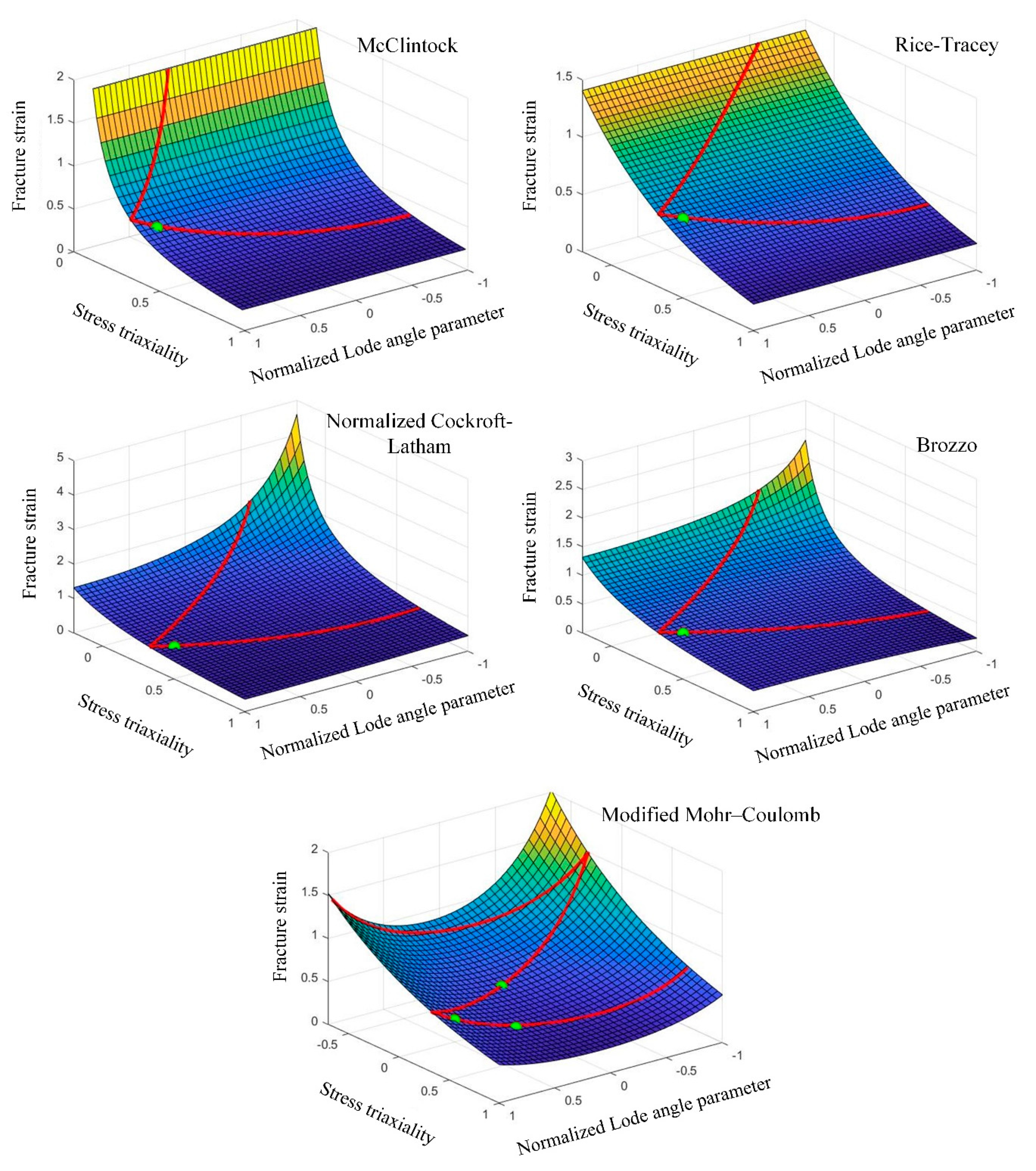
Figure 10 shows the predicted fracture envelope for each criterion. As observed, the fracture envelope of the material is not only dependent on the criterion used but also significantly affected by the calibration tests. Among the studied criteria, only the Normalized Cockroft–Latham, Brozzo, and MMC criteria can predict the fracture envelope by considering both and . The McClintock criterion fails to predict the fracture limit for . For this reason, it was calibrated using only two uniaxial tension and plane strain tests. This criterion is known as a criterion capable of predicting only tensile fracture [31].

Figure 10.
The fracture envelope of the AA6082-T4 sheet predicted by the different criteria in the space of , and . Note: the calibration test of the McClintock, Rice–Tracey, Normalized Cockroft–Latham, and Brozzo criteria is the uniaxial tension test.
5.2. Evaluation of Fracture Criteria
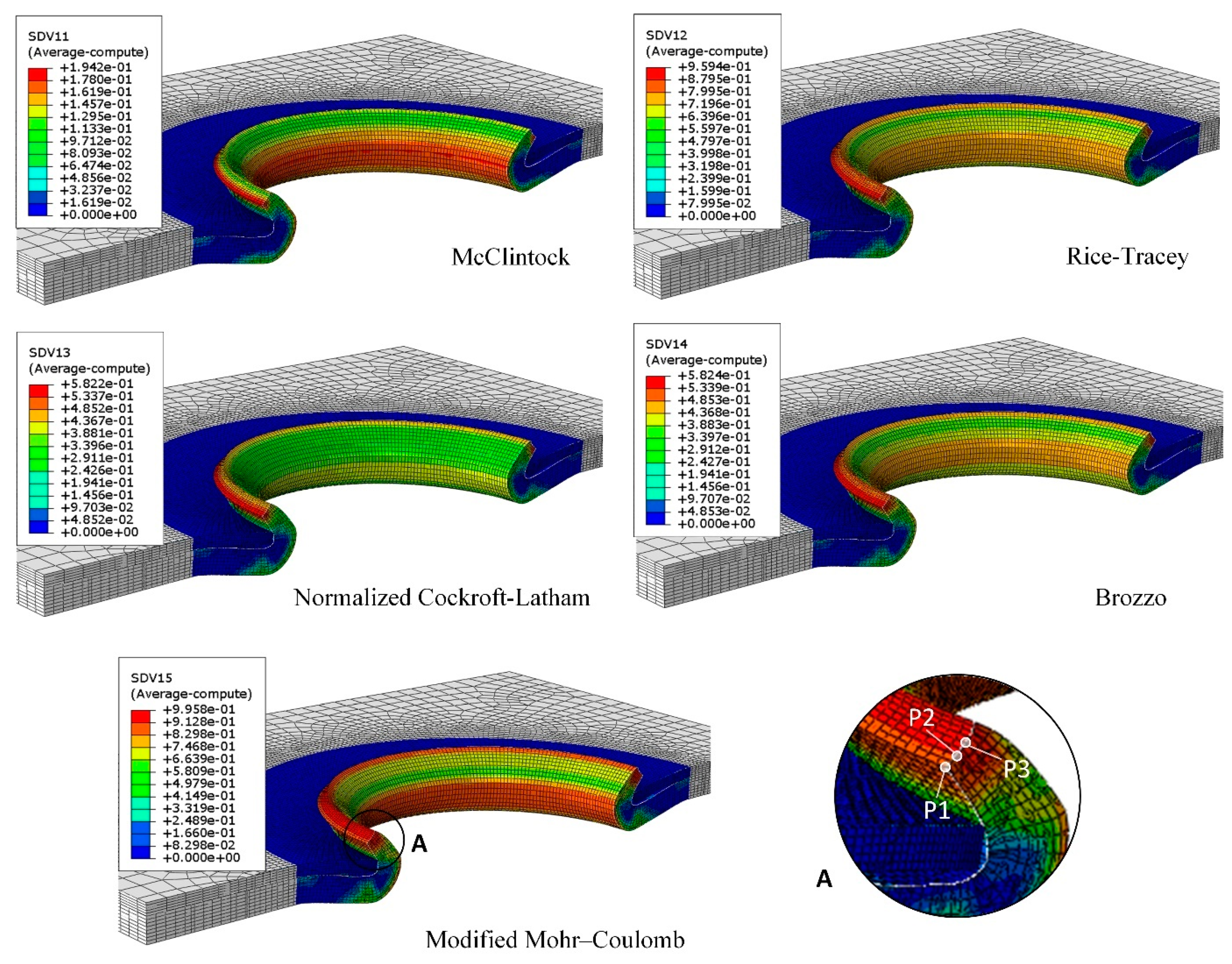
The experimental tests were conducted with different displacements ranging from 8 to 9.2 mm for the hemming punch to determine the onset of fracture. The results showed that if the joint is formed in an axially symmetrical manner, fracture begins at a displacement of 8.6 mm at the flange edge. Figure 11 illustrates the predicted damage distribution by the ductile fracture criteria at this displacement. It can be observed that while all the criteria correctly identify the flange edge as the critical area, there are variations in the predicted damage distribution.
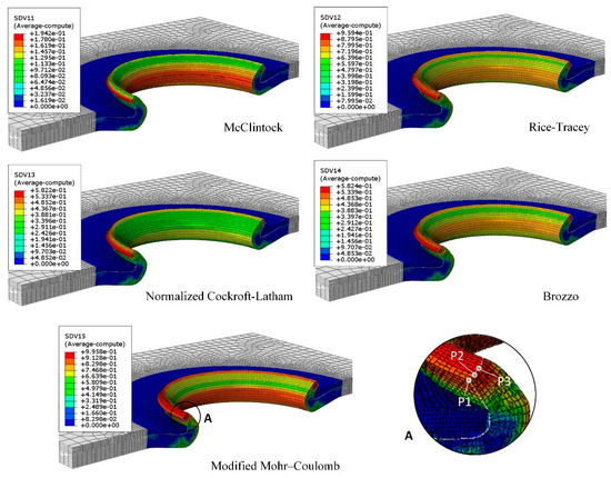
Figure 11.
Damage distribution predicted by the different criteria in the outer sheet made of the AA6082-T4 at the hemming punch displacement of 8.6 mm.
The McClintock, Rice–Tracey, Normalized Cockroft–Latham, and Brozzo criteria predict the highest amount of damage on the outer side of this area, with the damage decreasing towards the inner side. Among these criteria, the McClintock criterion exhibits more pronounced changes in the damage amount from the outer to the inner side. On the other hand, the MMC criterion predicts the maximum damage at the center of the flange edge, with the inner side experiencing more damage compared to the outer side. Another noteworthy observation in Figure 11 is the disparity in the severity of predicted damage in the bend area of the flange. The McClintock and MMC criteria forecast relatively higher damage intensity in this area compared to the other criteria.
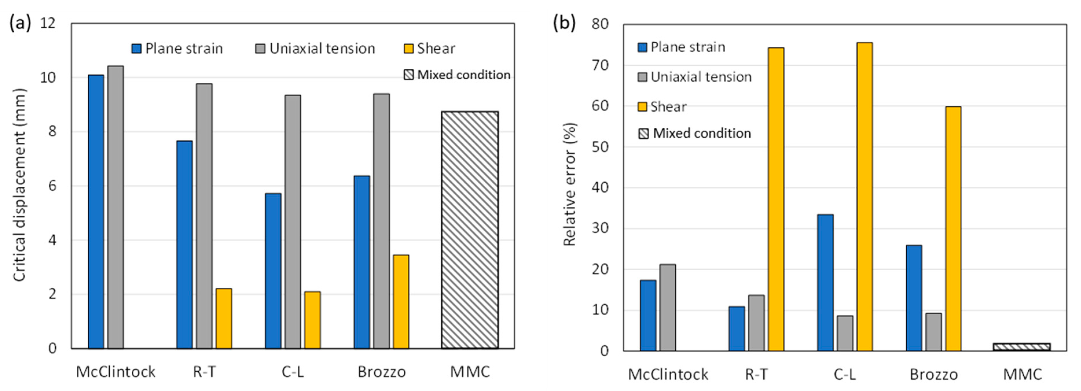
Figure 12 displays the critical displacement predicted for the hemming punch by different criteria, along with their corresponding errors. The MMC criterion exhibits the highest accuracy, as it is calibrated using all three calibration tests simultaneously. The accuracy of the other criteria depends on the specific calibration test used. When calibrated using a shear test, these criteria result in the highest error, overestimating damage to the edge. However, when calibrated with the uniaxial tension test, the predicted displacement value exceeds the experimental value, leading to significantly improved accuracy in the predictions. For the plane strain test, the McClintock and Rice–Tracey criteria show higher prediction accuracy compared to when calibrated with the uniaxial tension test. However, this is not the case for the other single-constant criteria.
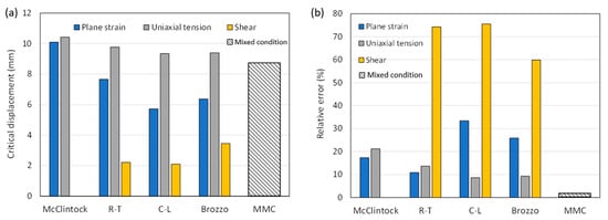
Figure 12.
(a) Critical displacement predicted by the fracture criteria calibrated under different stress states and (b) corresponding errors.
It should be noted that, except for the McClintock criterion, which predicts a critical displacement value greater than the experimental value when calibrated with the plane strain test, all the other single-constant criteria predict a lower critical displacement than the experimental value. Among the single-constant criteria, the Normalized Cockroft–Latham and Brozzo criteria exhibit the highest accuracy, with errors of 8.6% and 9.2%, respectively, obtained through calibration with the uniaxial tension test. As mentioned, these two criteria consider both and .
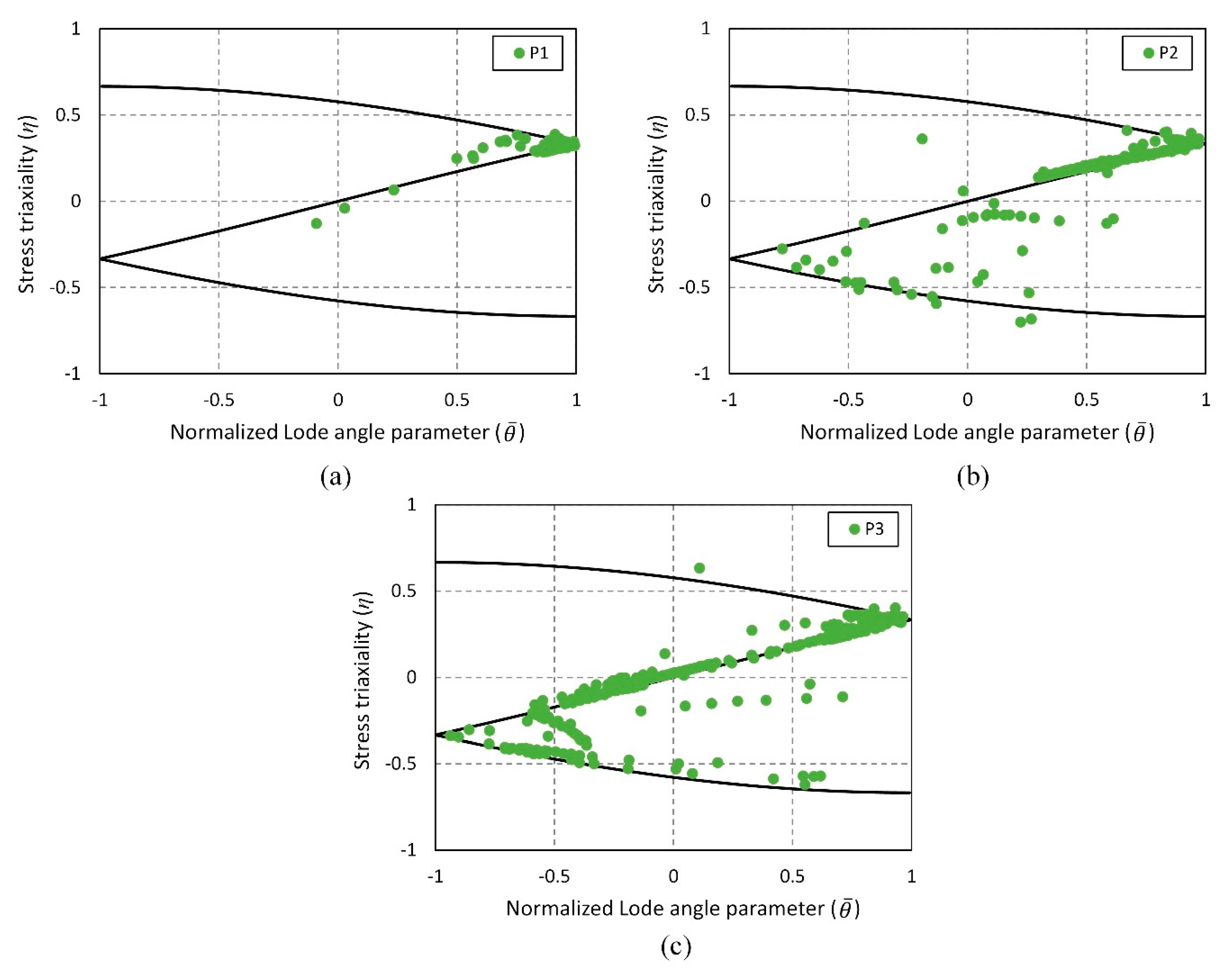
In order to understand the variations in the predictions of the fracture criteria, it is essential to examine the stress state in the critical area. Figure 13 illustrates the stress state at three points within the flange edge area, represented in the and space, during the hole hemming process. These points are located at the outer edge P1, representing the critical region predicted by the single-constant criteria, the center of the edge area P3, representing the critical region predicted by the MMC criterion, and an intermediate position P2, as depicted in Figure 11.
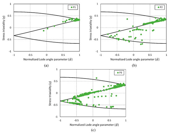
Figure 13.
Variation of stress triaxiality and normalized Lode angle parameter at the selected points during the hole hemming process: (a) P1, (b) P2, and (c) P3.
As can be seen, in all three regions, the stress state is close to the plane stress state, but there are variations in the in-plane loading state. On the outer side (P1), the stress state is predominantly characterized by uniaxial tension. This deformation is caused by the increase in the hole diameter of the outer sheet due to flanging and hemming operations. Moving towards the inner edge, where contact with the punches occurs, shear deformation arises due to the disparity in deformations on both sides of the edge area (P2). Additionally, compressive deformation occurs at the center point of the edge area due to the pressure exerted by the punches (P3). These variations in stress states are crucial because the aluminum sheet exhibits distinct fracture limits under these conditions. Therefore, for a criterion to make accurate predictions, it must consider and account for these differences.
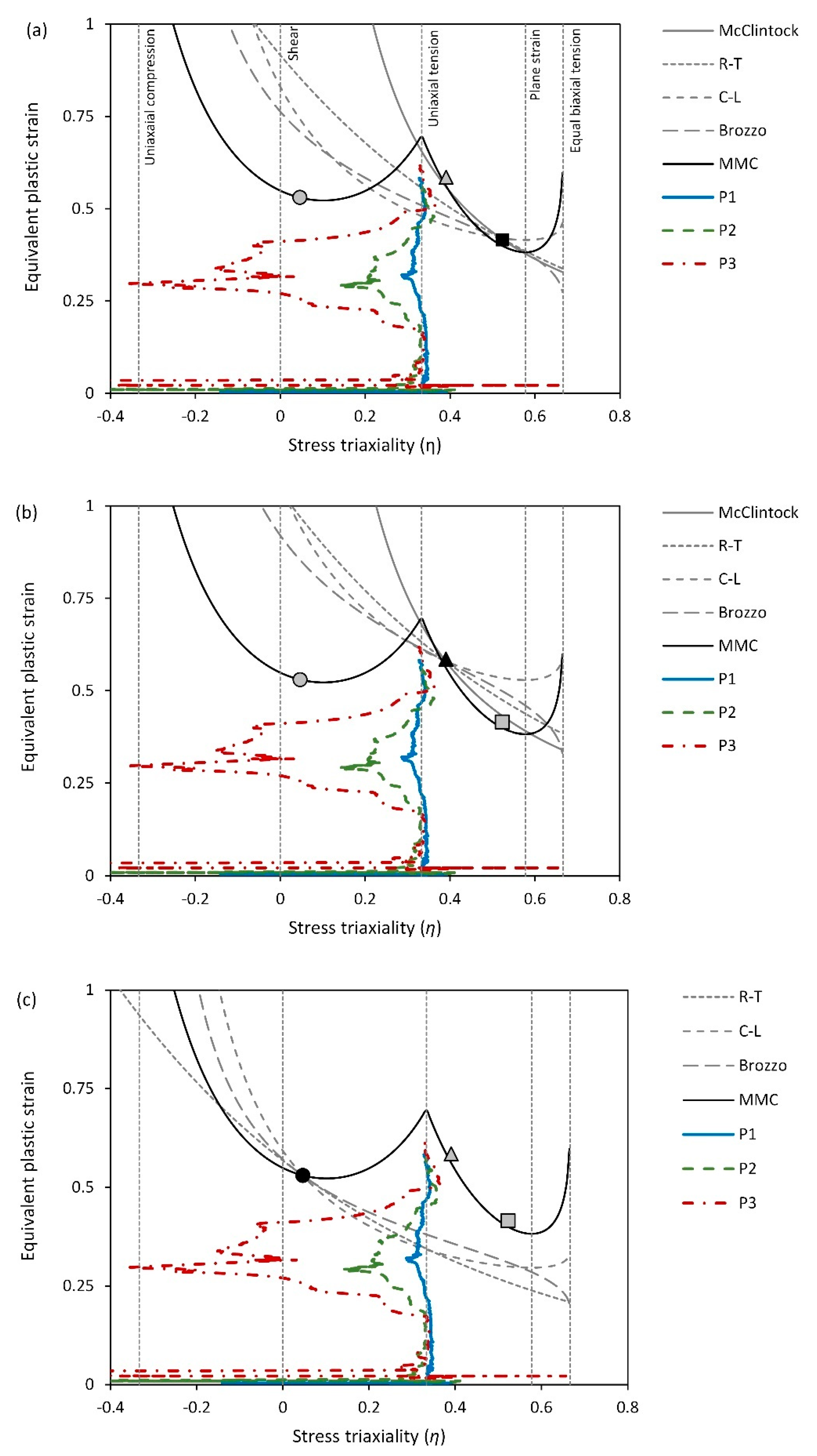
Considering that the plane stress state prevails in the studied points and Equation (16), which relates stress triaxiality and the normalized Lode angle parameter , is applicable to plot the deformation paths in a 2D space of stress triaxiality and equivalent plastic strain (see Figure 14). The fracture envelopes obtained under different calibration conditions are also plotted in this space. As observed, the deformation path at the outer side corresponds to the uniaxial tension mode. However, moving towards the center of the edge area, the deformation path shifts towards shear and uniaxial compression modes. This change in direction from uniaxial tension is accompanied by significant plastic deformation, which can result in substantial damage to the material.
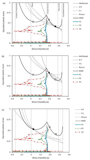
Figure 14.
Deformation path of the selected points during the hole hemming process against the fracture envelopes of the criteria calibrated with the different tests: (a) plane strain test, (b) uniaxial tension test, and (c) shear test. Note: black marker indicats the calibration point for the single-constant criteria.
The single-constant criteria, characterized by a single branch, tend to predict higher fracture strain values in shear compared to uniaxial tension, or they may not consider it at all, as in the case of the McClintock criterion. As a result, these criteria predict the maximum damage for the outer side of the flange edge area (P1). In the McClintock criterion, the difference between the amount of damage on the outer side and other points is noticeable, as this criterion only calculates the damage for plastic deformation in stress states with positive stress triaxiality.
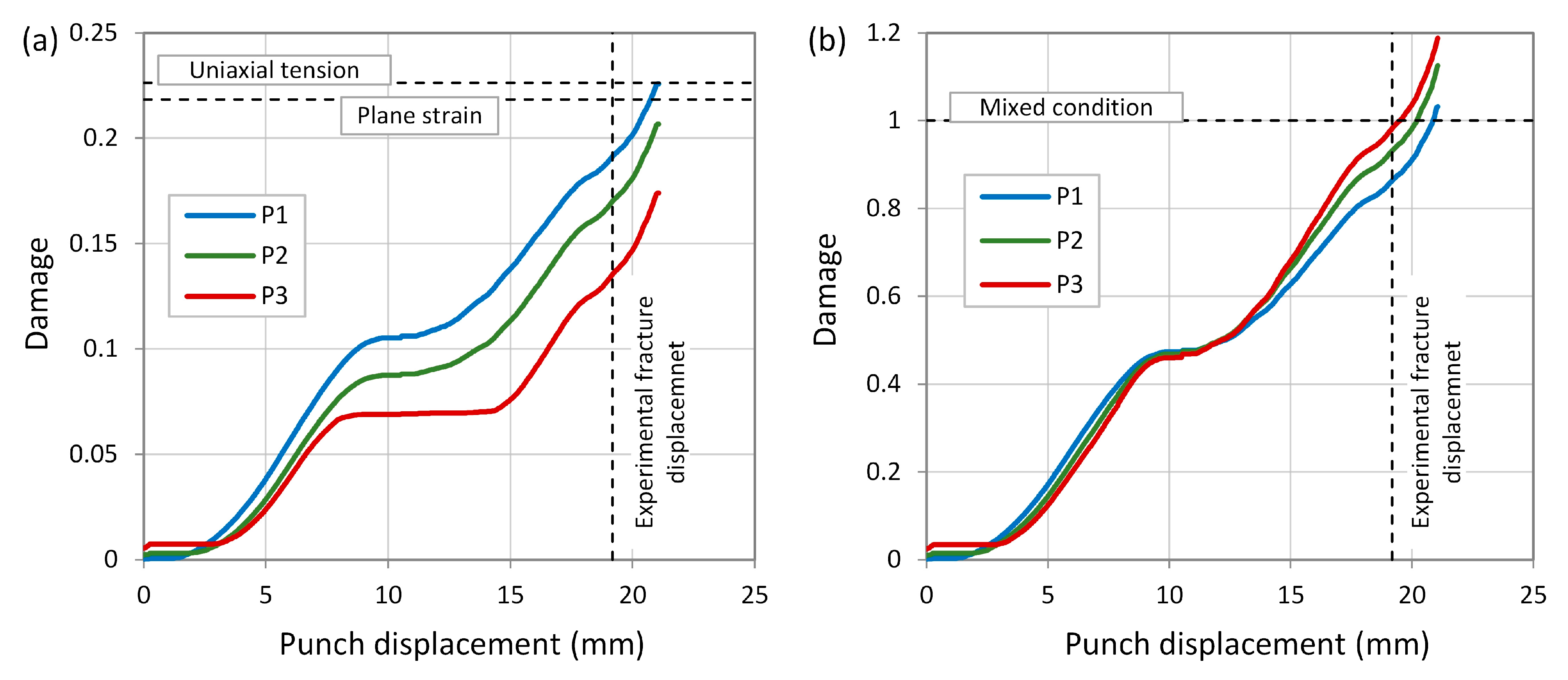
The history of damage at these points also reveals the neglect of damage by the McClintock criterion when the shear mode prevails, causing the increase of damage to halt at the center point (P3), resulting in a plateau region (see Figure 15a). In the MMC criterion, the failure limit comprises two branches that converge in the state of pure uniaxial tension. In this criterion, the fracture limit in pure shear mode is lower than that in pure uniaxial tension. As a result, at the second and third points, as the deformation path shifts towards shear mode, damage accumulates more and more compared to the first point (refer to Figure 15b). However, by approaching the inner side of the flange, which is affected by the pressure applied by the punches, the amount of damage slightly decreases due to the increased fracture limit compared to pure shear mode. Thus, the MMC criterion predicts maximum damage at the center of the edge area (P3), with the region closer to the inner side exhibiting higher damage compared to the area closer to the outer side.
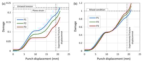
Figure 15.
History of damage to the selected points during the hole hemming process: (a) McClintock criterion and (b) MMC criterion.
As seen in Figure 14, the fracture envelope of the single-constant criteria is strongly influenced by the choice of calibration test so that when the uniaxial tension test is selected as the calibration test, the fracture envelopes reach their highest level compared to other calibration tests. In this case, as observed, the single-constant criteria predict the fracture limit in shear to be significantly higher than the experimental value. As a result, the damage at the points undergoing deformation with this mode is calculated to be less than the actual value, leading to the prediction of a fracture displacement that exceeds the experimental value for all the single-constant criteria. However, the criteria calibrated under the uniaxial tension mode, which is one of the dominant deformation modes at the edge, generally exhibit higher accuracy compared to others (8.6% < error < 21.3%). On the contrary, when the shear test is used, the fracture envelopes are located at the lowest level compared to the other two calibration tests. As a result, the fracture limit in uniaxial tension and plane strain is predicted to be much lower than the experimental value, leading to all the criteria predicting the fracture displacement much lower than the experimental value (error > 59%). It should be noted that the McClintock cannot be calibrated under shear, which is why its fracture envelope has not been drawn. By calibrating the single-constant criteria with the plane strain test, the fracture envelope predicted by the McClintock criterion does not change significantly, but the other fracture envelopes are placed between the predicted fracture envelopes obtained using the uniaxial and shear tests. Although the accuracy of the predictions may be acceptable for some criteria, this calibration test is not recommended because the loading mode in this test differs from what occurs at the edge of the flange edge, which hinders a physically understandable interpretation of the results.
With three constants, the MMC criterion effectively models the failure strain under different loadings. Therefore, it can accurately predict the moment of failure in the flange edge, which undergoes a combination of different loading modes, particularly uniaxial tension and shear. Based on the obtained results, it can be concluded that simultaneous consideration of material fracture behavior in both uniaxial tension and shear, where the left branch of the MMC criterion is located, is necessary to predict fracture at the flange edge in the hole hemming process. Although the bend area of the flange is not as critical as the edge, to accurately predict fracture in this area, it is important to model the material’s fracture behavior under plane strain, where the right branch of the MMC criterion is defined. Among the studied criteria, the MMC criterion is the only one that allows for modeling the material’s fracture behavior in three modes: plane strain, uniaxial tension, and shear, simultaneously. Among the single constant criteria, the McClintock criterion is the only one that can acceptably model both the fracture limits of the material in plane strain and uniaxial tension. This is why, in addition to the edge area of the flange, the bend area has also been identified as a critical area by the MMC and McClintock criteria.
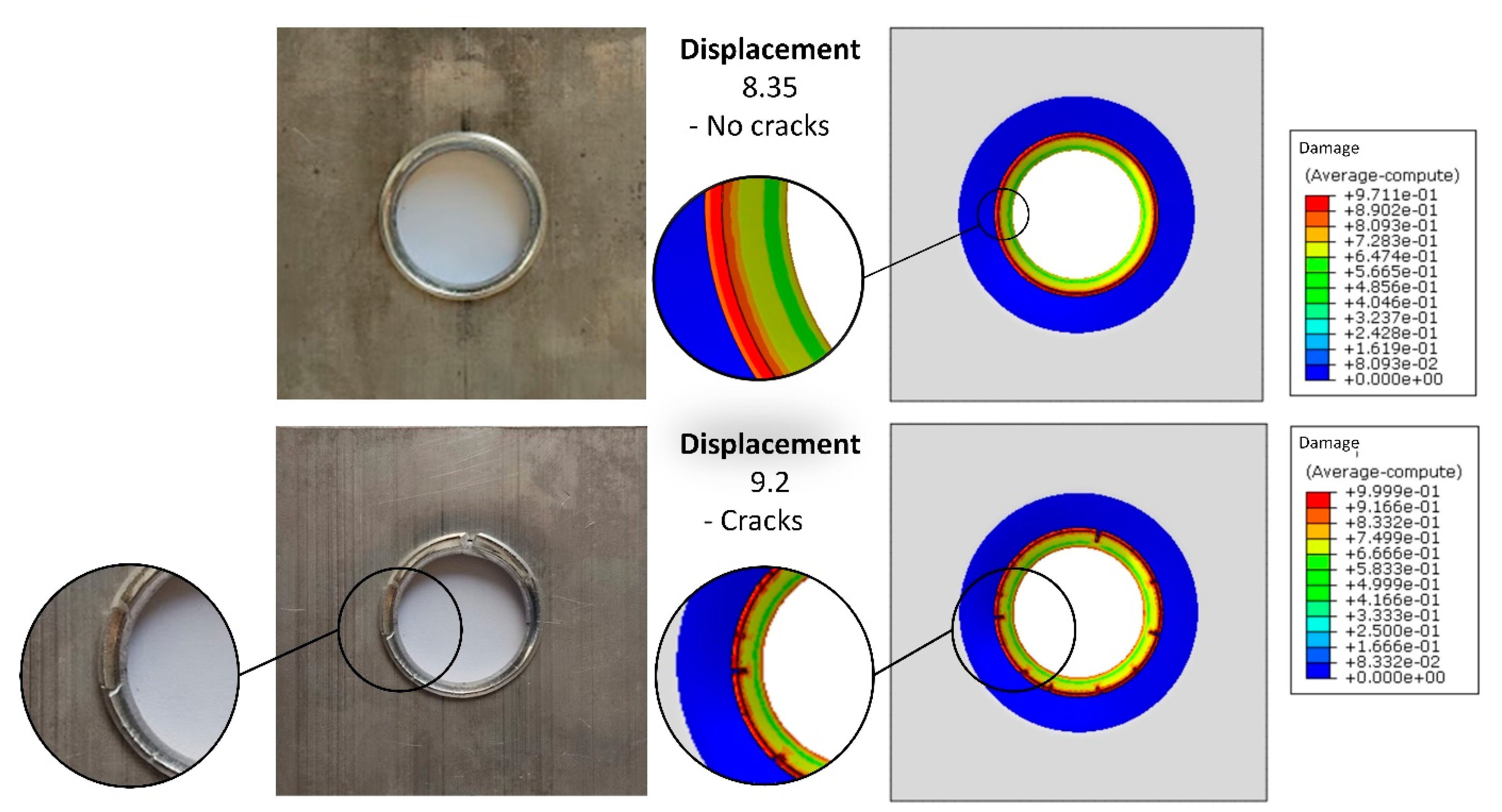
Figure 16 shows the comparison of the joint obtained in the experimental test, and that predicted using the finite element simulation. In this simulation, crack initiation and propagation were predicted based on the MMC criterion and using the element deletion technique. As seen, at a displacement of 8.35 mm, although the amount of damage at the edge is very high, it has not yet reached one. Thus, a crack is not observed at the edge of the flange, similar to the experimental sample. However, with an increase in displacement to 9.2 mm, the edge breaks. As observed, the MMC criterion can accurately model the crack initiation at the edge and its propagation towards the bend area.

Figure 16.
Comparison of the hole hemmed joints obtained from the experimental tests and from the FE simulations involving the MMC criterion at hemming punch displacements of 8.35 mm and 9.2 mm.
6. Conclusions and Future Perspectives
This paper addressed the main challenge in the novel hemming process for joining aluminum and magnesium sheets with different formability. To achieve this, the hardening and yielding behavior of the materials were first characterized. Subsequently, the capabilities of five different criteria, including the McClintock, Rice–Tracey, Normalized Cockroft–Latham, Brozzo, and Modified Mohr–Coulomb (MMC) criteria, were evaluated by considering different calibration tests. The results showed that all the criteria identified the flange edge of the outer sheet (AA6082-T4) as a critical area prone to fracture. However, the single-constant criteria (McClintock, Rice–Tracey, Normalized Cockroft–Latham, and Brozzo) predicted maximum damage for its outer edge subjected to uniaxial tension, while the MMC criterion predicted maximum damage for its center, where combined uniaxial tensile and shear deformation mainly occurs. This difference is due to the single-constant criteria overestimating the fracture limit in shear, whereas the MMC criterion can accurately model the fracture behavior of the aluminum sheet simultaneously in uniaxial tension and shear. As a result, the MMC criterion was able to predict the critical displacement of the hemming punch with an error of about 1%. The fracture envelope of the single-constant criteria was strongly dependent on the stress state under which they were calibrated so that the highest errors in predicting the critical displacement of the hemming punch were related to the criteria calibrated under shear (error > 59%), while the lowest errors were related to the criteria calibrated under uniaxial tension (8.6% < error < 21.3%). It was also found that to correctly predict the damage in the flange bending area of the outer sheet, a criterion should be able to model the fracture behavior of the material from plane strain to uniaxial tension, and only the MMC and McClintock criteria showed this capability. The comparison of the joint obtained in the experimental tests and the numerical simulations confirmed that the MMC criterion can accurately predict crack initiation and propagation at the flange edge. Thus, this criterion is recommended for predicting ductile fracture in the hole hemming process.
In future research, a unique hole design with radial branches will be assessed to minimize damage to the flange edge and enhance the joinability of the materials. This new design is expected to result in a larger mechanical lock and a smaller residual hole radius in the connection. Additionally, the capability of the hole hemming process to connect metal sheets to polymer and composite sheets will be tested.
Author Contributions
Conceptualization, M.M.K.; methodology, M.M.K.; software, M.M.K. and J.A.C.P.; validation, M.M.K. and J.A.C.P.; formal analysis, M.M.K. and J.A.C.P.; investigation, M.M.K., J.A.C.P., R.J.C.C. and E.A.S.M.; resources, R.J.C.C. and E.A.S.M.; data curation, M.M.K. and J.A.C.P.; writing—original draft preparation, M.M.K.; writing—review and editing, M.M.K., R.J.C.C., E.A.S.M. and L.F.M.d.S.; visualization, M.M.K.; supervision, M.M.K., R.J.C.C. and L.F.M.d.S.; project administration, M.M.K. and L.F.M.d.S.; funding acquisition, L.F.M.d.S. All authors have read and agreed to the published version of the manuscript.
Funding
MM Kasaei expresses gratitude for the funding received from operation NORTE-06-3559-FSE-000107—Contratação de Recursos Humanos Altamente Qualificados (PME ou CoLAB), supported by Norte 2020 through Fundo Social Europeu.
Data Availability Statement
Not applicable.
Conflicts of Interest
The authors declare no conflict of interest.
References
- Kasaei, M.M.; Beygi, R.; Carbas, R.J.C.; Marques, E.A.S.; da Silva, L.F.M. A review on mechanical and metallurgical joining by plastic deformation. Discov. Mech. Eng. 2023, 2, 5. [Google Scholar] [CrossRef]
- Guilleaume, C.; Brosius, A. Cross-rolling process for manufacturing lightweight hybrid components. J. Adv. Join. Process. 2021, 3, 100063. [Google Scholar] [CrossRef]
- Lipman, T.E.; Maier, P. Advanced materials supply considerations for electric vehicle applications. MRS Bull. 2021, 46, 1164–1175. [Google Scholar] [CrossRef]
- Wischer, C.; Wiens, E.; Homberg, W. Joining with versatile joining elements formed by friction spinning. J. Adv. Join. Process. 2021, 3, 100060. [Google Scholar] [CrossRef]
- Viswanadhapalli, B.; Bupesh Raja, V. Application of magnesium alloys in automotive industry-a review. Emerg. Trends Comput. Expert Technol. 2020, 35, 519–531. [Google Scholar]
- Shah, L.H.; Othman, N.H.; Gerlich, A. Review of research progress on aluminium–magnesium dissimilar friction stir welding. Sci. Technol. Weld. Join. 2018, 23, 256–270. [Google Scholar] [CrossRef]
- Han, S.; Li, Z.; Wang, Z.; Li, Y. Review on joining processes of magnesium alloy sheets. Int. J. Adv. Manuf. Technol. 2022, 118, 2787–2803. [Google Scholar] [CrossRef]
- Beygi, R.; Pouraliakbar, H.; Torabi, K.; Eisaabadi, B.G.; Fallah, V.; Kim, S.K.; Shi, R.; da Silva, L.F.M. The inhibitory effect of stir zone liquefaction and eutectic-phase formation on the growth of γ/β intermetallics during dissimilar FSW of Al/Mg alloys. J. Manuf. Process. 2021, 70, 152–162. [Google Scholar] [CrossRef]
- Li, Y.; Qin, F.; Liu, C.; Wu, Z. A Review: Effect of Friction Stir Welding on Microstructure and Mechanical Properties of Magnesium Alloys. Metals 2017, 7, 524. [Google Scholar] [CrossRef]
- Liu, L. Welding and Joining of Magnesium Alloys; Elsevier: Amsterdam, The Netherlands, 2010. [Google Scholar]
- Meschut, G.; Merklein, M.; Brosius, A.; Drummer, D.; Fratini, L.; Füssel, U.; Gude, M.; Homberg, W.; Martins, P.A.F.; Bobbert, M.; et al. Review on mechanical joining by plastic deformation. J. Adv. Join. Process. 2022, 5, 100113. [Google Scholar] [CrossRef]
- Neugebauer, R.; Kraus, C.; Dietrich, S. Advances in mechanical joining of magnesium. CIRP Ann. 2008, 57, 283–286. [Google Scholar] [CrossRef]
- Domitner, J.; Silvayeh, Z.; Predan, J.; Auer, P.; Stippich, J.; Enzinger, N.; Gubeljak, N. Load-bearing capacity of hybrid riv-bonded aluminum-magnesium joints at quasi-static and cyclic loadings. J. Manuf. Process. 2023, 87, 133–140. [Google Scholar] [CrossRef]
- Neugebauer, R.; Dietrich, S.; Kraus, C. Dieless clinching and dieless rivet-clinching of magnesium. Key Eng. Mater. 2007, 34, 693–698. [Google Scholar] [CrossRef]
- Li, Y.; Wei, Z.; Wang, Z.; Li, Y. Friction Self-Piercing Riveting of Aluminum Alloy AA6061-T6 to Magnesium Alloy AZ31B. J. Manuf. Sci. Eng. 2013, 135, 061007. [Google Scholar] [CrossRef]
- Kasaei, M.M.; da Silva, L.F. Joining sheets made from dissimilar materials by hole hemming. Proc. Inst. Mech. Eng. Part L J. Mater. Des. Appl. 2022, 236, 1321–1332. [Google Scholar] [CrossRef]
- Pereira, J.A.C.; Kasaei, M.M.; Carbas, R.J.C.; Marques, E.A.S.; Lim, H.; da Silva, L.F.M. Joining magnesium and aluminum alloy sheets by a novel hole hemming process. Thin-Walled Struct. 2023, 187, 110758. [Google Scholar] [CrossRef]
- Haran-Nogueira, A.; Kasaei, M.M.; Akhavan-Safar, A.; Carbas, R.J.C.; Marques, E.A.S.; Kim, S.K.; da Silva, L.F.M. Development of hybrid bonded-hole hemmed joints: Process design and joint characterization. J. Manuf. Process. 2023, 95, 479–491. [Google Scholar] [CrossRef]
- Haran-Nogueira, A.; Kasaei, M.M.; Akhavan-Safar, A.; Carbas, R.J.C.; Marques, E.A.S.; da Silva, L.F.M. Failure analysis of hybrid bonded-hole hemmed joints for dissimilar materials. Thin-Walled Struct. 2023, 189, 110907. [Google Scholar] [CrossRef]
- Badparva, H.; Naeini, H.M.; Kasaei, M.M.; Asl, Y.D.; Abbaszadeh, B.; da Silva, L.F.M. Deformation length in flexible roll forming. Int. J. Adv. Manuf. Technol. 2023, 125, 1229–1238. [Google Scholar] [CrossRef]
- Conceição, A.G.C.; Kasaei, M.M.; Carbas, R.J.C.; Marques, E.A.S.; da Silva, L.F.M. A flexible tool for joining dissimilar materials by the novel hole hemming process. Mech. Based Des. Struct. Mach. 2023, 1–29. [Google Scholar] [CrossRef]
- Kasaei, M.M.; Oliveira, M.C. Influence of the contact with friction on the deformation behavior of advanced high strength steels in the Nakajima test. J. Strain Anal. Eng. Des. 2022, 57, 193–207. [Google Scholar] [CrossRef]
- Khademi, M.; Naeini, H.M.; Mirnia, M.J.; Kasaei, M.M.; da Silva, L.F. Fracture prediction of AA6061-T6 sheet in bending process using Gurson–Tvergaard–Needleman model. Proc. Inst. Mech. Eng. Part L J. Mater. Des. Appl. 2022, 1–14. [Google Scholar] [CrossRef]
- Talebi-Ghadikolaee, H.; Naeini, H.M.; Mirnia, M.J.; Mirzai, M.A.; Gorji, H.; Alexandrov, S. Fracture analysis on U-bending of AA6061 aluminum alloy sheet using phenomenological ductile fracture criteria. Thin-Walled Struct. 2020, 148, 106566. [Google Scholar] [CrossRef]
- Nielsen, C.V.; Martins, P.A.F. Chapter 2—Formability. In Metal Forming; Nielsen, C.V., Martins, P.A.F., Eds.; Academic Press: Cambridge, MA, USA, 2021; pp. 7–107. [Google Scholar]
- Heyser, P.; Petker, R.; Meschut, G. Development of a numerical simulation model for self-piercing riveting of additive manufactured AlSi10Mg. Proc. Inst. Mech. Eng. Part L J. Mater. Des. Appl. 2023, 237, 1826–1835. [Google Scholar] [CrossRef]
- Wiesenmayer, S.; Merklein, M. Potential of shear-clinching technology for joining of three sheets. J. Adv. Join. Process. 2021, 3, 100043. [Google Scholar] [CrossRef]
- Barimani-Varandi, A.; Aghchai, A.J.; Lambiase, F. Failure behavior in electrically-assisted mechanical clinching joints. J. Manuf. Process. 2021, 68, 1683–1693. [Google Scholar] [CrossRef]
- Martins, P.A.F.; Bay, N.; Tekkaya, A.E.; Atkins, A.G. Characterization of fracture loci in metal forming. Int. J. Mech. Sci. 2014, 83, 112–123. [Google Scholar] [CrossRef]
- Bai, Y.; Wierzbicki, T. Application of extended Mohr–Coulomb criterion to ductile fracture. Int. J. Fract. 2010, 161, 1–20. [Google Scholar] [CrossRef]
- Isik, K.; Silva, M.B.; Tekkaya, A.E.; Martins, P.A.F. Formability limits by fracture in sheet metal forming. J. Mater. Process. Technol. 2014, 214, 1557–1565. [Google Scholar] [CrossRef]

Disclaimer/Publisher’s Note: The statements, opinions and data contained in all publications are solely those of the individual author(s) and contributor(s) and not of MDPI and/or the editor(s). MDPI and/or the editor(s) disclaim responsibility for any injury to people or property resulting from any ideas, methods, instructions or products referred to in the content. |
© 2023 by the authors. Licensee MDPI, Basel, Switzerland. This article is an open access article distributed under the terms and conditions of the Creative Commons Attribution (CC BY) license (https://creativecommons.org/licenses/by/4.0/).