Abstract
The developed microstructure and the tensile behavior of a 316L-type steel produced by selective laser melting were studied. This paper particularly aims to clarify the dislocation substructures in the developed steel, focusing on the density of dislocations, their arrangement in cells/subgrains, related internal distortions, and specific strengthening. The experimental samples were obtained using a 3D selective laser melting system ProX200 (laser power of 240 W, beam speed of 1070 mm/s, distance between tracks of 80 µm, and layer thickness of 30 µm) in a nitrogen atmosphere. The steel microstructure was characterized by a grain size of 20 μm and a high dislocation density of 5 × 10¹⁴ m−2 in the grain/subgrain interiors. The rather strong fiber texture of <012> along the building direction resulted in different Taylor factors of 2.89 and 3.30 for tension along the building direction and the side direction, respectively. The yield strength of 645 ± 5 MPa, the ultimate tensile strength of 750 ± 10 MPa, and an elongation of 40 ± 5% were obtained with a tensile test along the side direction. The rough calculation of the strengthening mechanisms suggested that the solid solution strengthening of 273 MPa and the dislocation strengthening of 262 MPa were the main contributors to the yield strength. Such a combination of strengthening from solid solution and homogeneously distributed numerous dislocations provides the processed steel with sufficient strengthening ability, leading to an outstanding strength–ductility combination.
1. Introduction
Additive technologies are being used more and more widely. High-tech industries, particularly those concerned with the manufacture of biomedical implants, are considered one of the promising areas for the use of additive technologies. Together with computed tomography, the use of additive technologies will make it possible to manufacture implants of unique shapes that correspond to the individual biological characteristics of patients.
Among various metals and alloys, 316L-type austenitic stainless steel is one of the most frequently used materials for applications in medicine [1]. This steel exhibits a beneficial combination of its physical and mechanical properties, including corrosion resistance, formability, and strength–plasticity balance. The mechanical properties of metallic materials depend significantly on the microstructural design of the metal/alloy [2,3]. Such microstructural parameters as the grain size, the dislocation density, the dispersed particles, and any distortions of the crystal lattice are the most important for mechanical properties. Therefore, the comprehensive analysis of the microstructure developed in the metallic products is of great practical importance. The microstructure control is especially vital for the products designed for any medical applications that deal directly with human health. Regarding austenitic stainless steels, it should be noted that they are commonly characterized by relatively low stacking fault energy (SFE), which substantially affects the dislocation motion. Namely, these steels demonstrate pronounced strain hardening [4,5,6]. The latter is attributed to the dislocation dissociation into partials that leads to suppressing dynamic recovery. The rapid increase in the dislocation density caused by even small plastic deformation has been proven to strengthen steel samples remarkably [7]. Hence, the yield strength, i.e., one of the crucial properties affecting mechanical performance, of the developed 316L stainless steel products is governed to a large extent by the dislocation substructure.
The samples of austenitic stainless steel obtained by 3D printing were characterized by a good combination of strength properties, including tensile, fatigue, and impact strengths [8,9,10,11]. On the other hand, the ductility of these steels leaves something to be desired [12,13]. The relatively low plasticity of steels produced by 3D printing is commonly considered to be a result of printing imperfections in the microstructure [13]. The steel samples obtained by selective laser melting are characterized by complicated microstructures consisting of a large number density of grain boundaries because of irregular grain shape, various inclusions together with second-phase precipitates, and well-developed spatial dislocation substructure [14]. Therefore, various strengthening mechanisms, such as grain size strengthening, dispersion strengthening, and dislocation strengthening, could be responsible for the enhanced strength of austenitic stainless steel samples developed by selective laser melting [15]. The superior strain hardening ability of austenitic stainless steel suggests that increasing the yield strength is associated with a high dislocation density. The cell substructure was considered to be the main contributor to the yield strength, although details of the dislocation substructure were not revealed [16]. The dislocation density at a level of 1014 m−2 generated by the direct energy deposition process was suggested to provide the yield strength of about 300–400 MPa for a 316L stainless steel [17]. In contrast, the strengthening mechanisms which result in a yield strength well above 500 MPa, along with the sufficient ductility of the 316L-type steels obtained by selective laser melting, deserve more detailed quantitative analysis [9,10]. Evaluating the dislocation strengthening in comparison with other possible strengthening mechanisms is of great practical importance. Such an approach allows us to predict the effect of initial strengthening on the following deformation behavior, including the operating deformation mechanisms and associated stages of strain hardening, the strain localization, and the achievable ultimate tensile strength.
The purpose of this work, therefore, is to evaluate the strengthening mechanisms of 316L-type steel obtained by selective laser melting. The present study is focused on the fine peculiarities of the developed microstructure and their effect on the steel performance. The latter is mainly related to the mechanical behavior, although possible variations of the steel microstructure/property upon subsequent thermo-mechanical processing are also considered in some detail.
2. Materials and Methods
Experimental samples were developed by selective laser melting using a 3D system ProX200 in a nitrogen atmosphere without platform preheating (Figure 1). The laser power of 240 W, the beam speed of 1070 mm/s, the distance between tracks of 80 µm, and the layer thickness of 30 µm were used for 3D printing with a strip style. The strip width was 5 mm, and the strip direction was changed in 90° from layer-to-layer. The dimensions of the built cuboids were 130 × 12 × 3 mm3. The chemical composition of the developed steel samples consists of 0.022 ± 0.001 C, 0.20 ± 0.005 N, 0.35 ± 0.001 Si, 1.11 ± 0.005 Mn, 17.1 ± 0.01 Cr, 12.6 ± 0.03 Ni, 2.56 ± 0.005 Mo, 0.01 ± 0.002%S, 0.02 ± 0.002%P, and Fe-balance (all in wt% as measured by a Foundry-Master OE750 optical emission spectrometer (Hitachi Ltd., Tokyo, Japan)). The porosity of 0.05% was revealed in the developed samples.
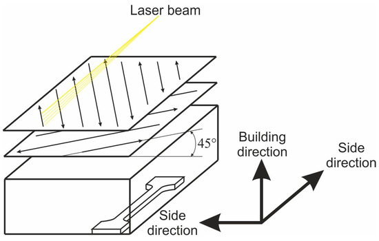
Figure 1.
Schematic for the sample processing by selective laser melting.
The microstructural investigations were carried out using a JEM-2100 transmission electron microscope (TEM, Jeol Ltd., Tokyo, Japan) equipped with an INCA X-ray energy dispersive spectrometer (XEDS) and an FEI Quanta 600 scanning electron microscope (SEM, FEI, Hillsboro, OR, USA) equipped with an electron back scattering diffraction pattern (EBSD) analyzer with TSL OIMTM software (version 6.2., Oxford Instruments, Oxford, UK) as orientation imaging microscopy (OIM). The samples for the TEM and SEM observations were electro-polished at a voltage of 20 V at room temperature using an electrolyte containing 10% perchloric acid and 90% acetic acid. The OIM images were collected with a step size of 1 μm or 0.2 μm for large-scale or fine-scale observations, respectively. The OIM images were subjected to a cleanup procedure; namely, the orientations with a confidence index below 0.15 were replaced by their confident neighbors. The dislocation density was measured by using the etch pit technique, which was modified for TEM analysis [18]. Namely, the dislocation density was evaluated counting the number of intersections of dislocations with the foil surfaces, using the multiple diffraction conditions to visualize all dislocations on four representative TEM images. Besides OIM, the misorientations of fine substructure were estimated with the Kikuchi-line technique using converged beam TEM technique [19]. The tensile tests were performed at an initial strain rate of 10−3 s−1 using an Instron 5882 universal testing machine (Instron Ltd., Norwood, MA, USA). Three tensile specimens with a gauge length of 16 mm and a cross section of 3 × 1.5 mm2 were cut from the middle portion of printed cuboids and tensioned along the side direction, i.e., perpendicular to the building direction.
3. Results
3.1. Developed Microstructures
A large-scale image of the developed microstructure in the 316L steel sample obtained by selective laser melting is shown in Figure 2. The developed microstructure is characterized by irregular-shaped grains with the mean grain size of 20 μm and the corresponding high number density of high-angle grain boundaries (Figure 2a). The developed grains involve large internal distortions, especially close to the grain boundaries, as revealed by the kernel average misorientation (KAM) distribution (Figure 2b). The distribution of KAM, including frequent traces of large KAM as short curls in Figure 2b, suggests the presence of numerous low-angle dislocation sub-boundaries. The gradual change in color within some grains in Figure 2a is also indicative of large misorientations in these grains along with high dislocation density, which is necessary to accommodate the large crystal rotations.
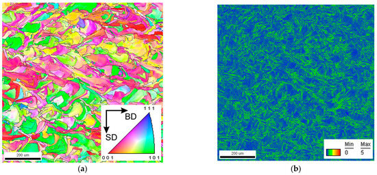
Figure 2.
Inverse pole figure orientation map (a) and kernel average misorientations (b) in a 316L steel sample processed by selective laser melting. Orientations in (a) are shown for the building direction.
The grain size distributions in the 316L steel sample developed by selective laser melting are shown in Figure 3. The distribution covers a rather large range of grain sizes from about 1 μm to 500 μm. The change in the number fraction for various grain sizes is characterized by a peak against 20 μm that corresponds to average grain size. It should be noted that the relatively large number fractions (about half of the peak) for small grain sizes below 4 μm are indicative of numerous fine grains in the developed sample. On the other hand, the coarse grains with a size above 100 μm occupy huge areas in spite of their small number fractions. Such a wide grain size distribution may be associated with the present grain shape, which is quite different from that in polygonal recrystallized microstructures obtained by conventional thermo-mechanical treatments. The irregular shape of the grains in the developed sample seems to be a trail of overlapping fine melting pools during 3D printing.
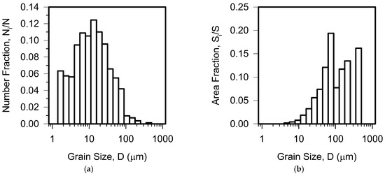
Figure 3.
Grain size distribution as number fraction (a) and area fraction (b) in a 316L steel sample processed by selective laser melting.
The developed microstructure consisting of irregular grains with large internal distortions is characterized by a specific grain boundary misorientation distribution (Figure 4). Namely, there is a high peak corresponding to small misorientation. The fraction of low-angle sub-boundaries with misorientations of 2° ≤ θ < 15° is about 0.5 in Figure 4. The fractions of high-angle grain boundaries with various misorientations in the range of 15° to 50° are almost the same, although a small peak can be recognized for misorientations of about 45°. Note that the peak for 45° misorientations is characteristic of random orientation distribution of cubes that is indicated by a solid line in Figure 4 [20]. Similar misorientation distributions of grain boundaries/sub-boundaries with nearly the same fractions of various high-angle boundaries and a large fraction of low-angle sub-boundaries were observed in ultrafine grained steels and alloys processed by severe plastic deformation [21,22].
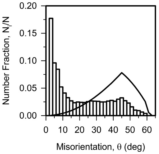
Figure 4.
Grain boundary misorientation distribution in a 316L steel sample processed by selective laser melting.
A magnified OIM image of the developed microstructure is shown in Figure 5. Frequently serrated and wavy grain boundaries are clearly seen in Figure 5a. This can be considered to be a feature of rapid crystallization during 3D printing by selective laser melting. The dislocation substructure can be roughly reflected by the distribution of KAM values (Figure 5b). Many low-angle sub-boundaries can be recognized by their large KAM values in Figure 5b. The appearance of large KAM (i.e., sub-boundaries) in Figure 5b clearly corresponds to the slight color change within a grain in Figure 5a. Setting a threshold value of 15°, an average value of KAM = 0.42° is obtained for the present sample. This KAM corresponds to a high dislocation density of ρ = 2 KAM/(b l) = 2.9 × 10¹⁴ m−2, where b and l are the Burgers vector and the OIM step size, respectively [23].
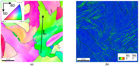
Figure 5.
Inverse pole figure orientation map for the building direction (a) and kernel average misorientations (b) in a 316L steel sample developed by selective laser melting.
The change in the orientation over a distance of about 65 μm within one grain along the line L in Figure 5a is represented in Figure 6. Several sharp peaks on the point-to-point misorientation distribution in Figure 6 correspond to low-angle sub-boundaries. Also, it can be clearly seen that gradual curvature within one grain may attain as large as 20° misorientation. These peaks on the point-to-point misorientation and the gradual change on the point-to-origin misorientation suggest that the high dislocation density as low-angle dislocation sub-boundaries and uniform cell substructure, respectively, evolved in the steel sample processed by selective laser melting.
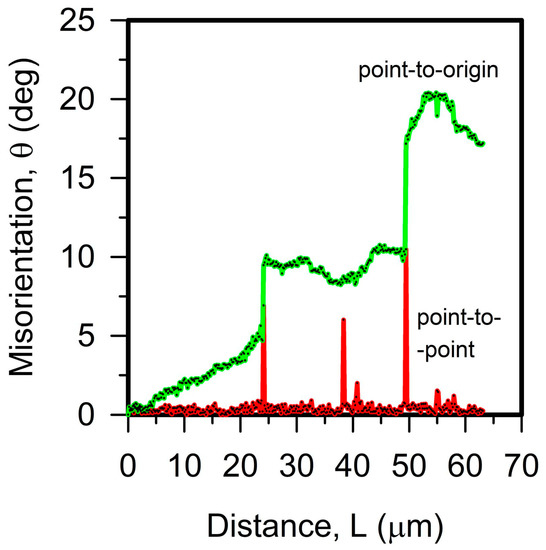
Figure 6.
Point-to-origin and point-to-point misorientations measured along the line indicated in Figure 5.
The TEM image of the fine substructure that evolved in the present steel sample is shown in Figure 7. The misorientations between the lettered points can be used to characterize the internal distortions. Using the converged beam technique, the precise orientation of a very small area within a grain/subgrain can be estimated by means of Kikuchi line analysis [19,24]. The large misorientations of θC–D = 24.8° and θE–F = 39.5° correspond to high-angle grain boundaries located along the building direction during 3D printing. A low-angle sub-boundary is located between B and C (θB–C = 3.3°). The gradual distortions borne by the dislocation cells correspond to misorientations of θA–B = 2.3° and θD–E = 2.3°. The same misorientations observed over the different distances in the fine substructure can be associated with dislocations with opposite Burgers vectors that change the crystal orientation in different directions. It is worth noting here that these TEM observations are quantitatively supported by the OIM analysis. Namely, the point-to-origin misorientation in Figure 6 exhibits both the portions with gradual misorientation change and the portions with almost constant misorientation. The latter can result from mutually compensated rotations of substructural cells due to unlike dislocations.
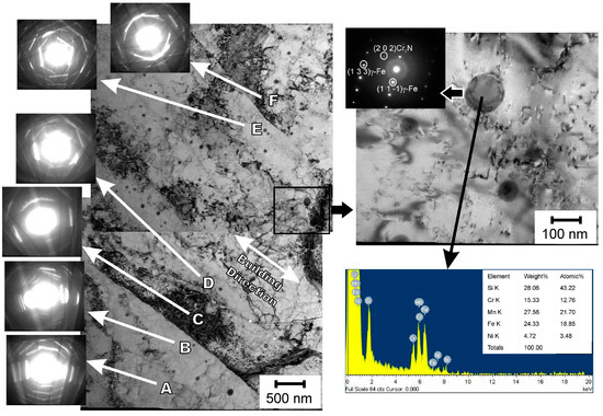
Figure 7.
Typical dislocation substructure in a 316L steel sample developed by selective laser melting. Misorientations between the lettered portions are θA–B = 2.3°, θB–C = 3.3°, θC–D = 24.8°, θD–E = 2.3°, and θE–F = 39.5°.
The large internal distortions evolved in the steel sample after selective laser melting correspond to the frequent bending contours on the TEM image. Such large distortions are caused by high dislocation density. The clear observable dislocations in the enlarged portion in Figure 7 can be counted individually to measure the dislocation density. Thus, the TEM observations revealed the dislocation density of ρ = 5 × 10¹⁴ m−2 in the cell substructure. The difference between the TEM and OIM calculations may be caused by an underestimation of dislocation density by OIM, because OIM neglects varying directions of dislocation Burgers vectors. The high dislocation density should be involved to accommodate large distortions aroused by a rapid cooling of the fine melting pools during the studied 3D printing. Large surface tensions leading to local distortions/strains were discussed as a result of high temperature gradient in selective laser melting process [25]. Besides high dislocation density, TEM observation revealed the fine dispersed precipitates homogeneously distributed throughout. The number of the precipitates per unit volume was NV = 3 × 10¹⁹ m−3 and their average size was d = 50 nm. XEDS and selected area diffraction in Figure 7 suggest that these precipitates may contain chromium nitride surrounded by silicon oxide enriched by manganese, although these precipitates should be the subject of further investigations.
3.2. Textures
Figure 8 shows the inverse pole figures for the building direction and side directions (two crosswise directions perpendicular to the building direction) for the steel sample built by 3D printing. Note that the side directions are located at 45° to the strip directions. The present steel sample is characterized by the rather strong fiber texture of <0 1 2> along the building direction. Similar results, i.e., the strong fiber texture consisting of a <0 1 1> spread towards <0 1 2>, have been obtained in other studies on 3D printing by selective laser melting of austenitic steels [14,26]. Some differences in the reported textures are related to the processing parameters altering the exact direction of the crystallization front. In contrast to the building direction, the side directions coincide with the crystallographic directions of <0 1 1> to < 1 1 1> (Figure 8). In other words, the side directions are characterized by a deficiency of <0 0 1>. This should be considered to be a specific textural feature of austenitic steel built up by selective laser melting. Such texture results in different Taylor factors (M) depending on the loading direction. For the studied sample, M = 2.89 and M = 3.30 are obtained by OIM analysis for tension along the building direction and the side direction, respectively.

Figure 8.
Inverse pole figures for a 316L steel sample processed by selective laser melting.
3.3. Tensile Behavior
The tensile stress vs. elongation curve for the present steel sample developed by 3D printing is shown in Figure 9. The main distinctive feature of the tensile behavior is the high yield strength of 645 ± 5 MPa, which is about twice of that in other 316L steels with recrystallized microstructure after conventional hot working (insert in Figure 9 [27]). Following the yielding, the tensile stress progressively increases with straining, approaching an ultimate tensile strength of 750 ± 10 MPa at an elongation of about 40%, and then necking gradually leads to failure at a total elongation of 47% in Figure 9. Hence, the present steel sample retains its strain-hardening ability in spite of significant strength in its original condition. The yield strength of austenitic steels can be easily increased by cold-to-warm working [28]. Austenitic steels with ultrafine grained microstructure and high dislocation density developed by severe plastic deformation exhibit yield strength well above 1000 MPa [29,30]. However, work-hardening of austenitic steels always leads to a degradation of plasticity. Exhausting the strain-hardening ability quickly shortens uniform elongation down to a few percent. This is a common tendency for austenitic steels, including chromium–nickel stainless steels and high-Mn TWIP/TRIP steels [7,30]. Promising results for strength–plasticity balance have been reported for austenitic steels subjected to small/warm deformation [7,29] or large deformation followed by recovery annealing [31]. A good combination of mechanical properties in austenitic steels has been attributed to a moderate density of dislocations arranged in a uniform cell substructure. A relatively low dislocation density promotes further strain hardening, whereas the number of dislocations in the initial substructure controls the yield strength.
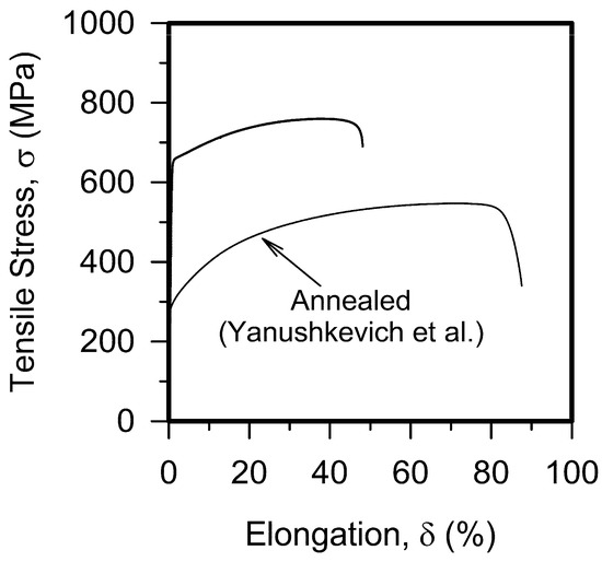
Figure 9.
The stress–strain curve for a 316L steel sample processed by selective laser melting. Insert shows the stress–strain curve for a 316L stainless steel with annealed recrystallized microstructure [27].
4. Discussion
The developed steel is characterized by a specific microstructure consisting of unequal grains bonded by wavy boundaries with high dislocation density and finely dispersed particles. As a result, the developed steel sample exhibits high yield strength well above 600 MPa. The strengthening mechanisms operating in the present case should involve the solid solution strengthening, the grain boundary strengthening, the dislocation strengthening, and the dispersion strengthening [15]. In spite of relatively low SFE, the stacking faults were hardly observed in the TEM images, which is indicative of quite a small distance for dislocation dissociation [32]. In turn, the small spacing between Shockley partials promotes dislocation slip instead of deformation twinning. Moreover, the dislocation slip commonly precedes the deformation twinning in face-centered cubic alloys, even in high-Mn steels with very low SFE [33]. Thus, the contribution of deformation twinning to the yield strength can be excluded.
The solid solution strengthening including the Peierls stress depends on the alloying extent and can be estimated as follows [34].
Here, N, C, Si, Cr, and Mo represent the corresponding chemical contents in wt%. The grain boundary (or grain size) strengthening can be calculated using the second term of the well-known Hall–Petch relationship [35,36].
where ky is a grain boundary strengthening factor of about 0.28 MPa m0.5 for annealed 316L austenitic stainless steel samples with recrystallized microstructure [37] and D is the mean grain size. The dislocation strengthening can be estimated using the Taylor-type equation [38,39].
where α is a dislocation strengthening factor of about 0.2 for face-centered cubic metals [15]. The dispersion strengthening can be expressed through the particle spacing (λ), assuming Orowan mechanism for dislocation motion as follows [15].
where M is the Taylor factor, G is the shear modulus, b is the Burgers vector (b = 0.258 nm for 316 stainless steels [40]), d is the particle size, and ν is the Poisson’s ratio. The particle spacing can be related to the particle number per unit volume (NV) as λ = (0.5 dNV)−0.5 − 0.82 d [15].
σSS = 63.5 + 496 N + 356.5 C + 20.1 Si + 3.7 Cr + 14.6 Mo,
σGB = ky D−0.5,
σρ = αMGbρ0.5,
σOr = 0.4 MGb ln(0.82 d/b)/(πλ(1 − ν)0.5),
The values of different strengthening contributors calculated by using Equations (1)–(4) are represented in Table 1. The calculated total strength of 638 MPa matches the experimental yield strength of 640 MPa well, although the solid solution strengthening seems to be overestimated, because some amount of nitrogen and chromium should be removed from solid solution for precipitation. Nevertheless, the yield strength of the present steel sample is governed by two major strengthening mechanisms, i.e., the solid solution and dislocation strengthening. Rare precipitates and relatively coarse grains do not contribute remarkably to the total strength. The large value of the solid solution strengthening results mainly from a relatively high nitrogen concentration, which could be caused by the nitrogen atmosphere used in the process of selective laser melting. Interstitials like carbon and nitrogen are commonly used to increase the strength of various steels and alloys [41,42,43]. In the present steel, the solid solution strengthening slows recovery, i.e., the dislocation redistribution and annihilation, during the selective laser melting process, and, therefore, promotes retaining the high number density of homogeneously distributed dislocations. In addition to the yield strength, the present steel has one more important advantage in its strain-hardening ability as compared to 316L steels obtained by 3D printing in an argon atmosphere [11,26]. Hence, the present steel is characterized by a relatively high yield strength combined with a rather large plasticity.

Table 1.
Strengthening contribution to the yield strength from the solid solution (σSS), the grain boundaries (σGB), the dislocation density (σρ), and the dispersed particles (σOr).
In the present case, the dislocation strengthening is provided by the dislocation forest mechanism because of the uniform dislocation distribution in the form of cell substructure. On the other hand, the huge volumes inside coarse grains that are homogeneously filled in dislocation cells retain the ability to strain hardening upon further deformation. The dislocation density in 316L stainless steel has reportedly increased up to an apparent saturation of about 5 × 10¹⁵ m−2 during large strain deformation at room temperature [28]. Therefore, the dislocation density leveled at 5 × 10¹⁴ m−2 in the steel samples developed by selective laser melting can be further increased by about an order of magnitude, which should provide remarkable hardening during subsequent deformation. Similar to austenite strengthening by recovered dislocation substructure [28,31], the dislocation cell substructure in the studied steel sample can be considered as a beneficial strengthening mechanism, increasing the strength without a substantial degradation of plasticity. Besides its mechanical properties, the high dislocation density in stainless steels processed by selective laser melting is favorable for the subsequent primary recrystallization upon post-printing annealing. The primary recrystallization can be used to improve the grain boundary character distribution in the framework of grain boundary engineering, although this interesting phenomenon should be the subject of further investigations.
5. Conclusions
The developed microstructures and mechanical properties of a 316L-type austenitic stainless steel produced by 3D printing by means of selective laser melting were studied. The main results can be summarized as follows.
- The developed microstructure consists of irregular grains with frequently serrated and curly grain boundaries. The mean grain size is 20 μm, whereas the wide grain size distribution covers the range from 1 μm to 500 μm. A relatively high density of lattice dislocations of 5 × 10¹⁴ m−2 arranged in a uniform dislocation cell substructure is observed in the grains. The developed texture is characterized by a remarkable deficiency of <0 0 1> along the direction perpendicular to the building direction.
- The developed steel sample exhibits the yield strength of 645 ± 5 MPa, the ultimate tensile strength of 750 ± 10 MPa, and total elongation of 40 ± 5%. The tensile behavior is mainly controlled by the solid solution and dislocation strengthening mechanisms, providing 273 MPa and 262 MPa, respectively, retaining remarkable abilities in terms of strain hardening and plasticity.
Author Contributions
Conceptualization, V.T. and A.B.; methodology, V.T.; validation, M.O. and M.T.; formal analysis, M.T.; investigation, M.O. and P.D.; resources, A.B.; writing—original draft preparation, M.O.; writing—review and editing, A.B.; visualization, P.D.; supervision, R.K.; project administration, M.T.; funding acquisition, R.K. All authors have read and agreed to the published version of the manuscript.
Funding
This research was funded by the Russian Science Foundation, Agreement number 22-43-02012.
Data Availability Statement
The data presented in this study are available on request from the corresponding author.
Acknowledgments
The work was carried out using the equipment of the Joint Research Center, Technology and Materials, of Belgorod National Research University.
Conflicts of Interest
The authors declare no conflict of interest.
References
- Lo, K.H.; Shek, C.H.; Lai, J.K.L. Recent developments in stainless steels. Mater. Sci. Eng. R Rep. 2009, 65, 39–104. [Google Scholar] [CrossRef]
- Dieter, G.E. Mechanical Metallurgy; McGraw-Hill Book Company: New York, NY, USA, 1961; p. 615. [Google Scholar]
- Dolzhenko, A.; Tikhonova, M.; Kaibyshev, R.; Belyakov, A. Microstructures and Mechanical Properties of Steels and Alloys Subjected to Large-Strain Cold-to-Warm Deformation. Metals 2022, 12, 454. [Google Scholar] [CrossRef]
- Ludwigson, D.C. Modified stress-strain relation for fcc metals and alloys. Metal. Trans. 1972, 2, 2825–2828. [Google Scholar] [CrossRef]
- Odnobokova, M.; Yanushkevich, Z.; Kaibyshev, R.; Belyakov, A. On the Strength of a 316L-Type Stainless Steel Subjected to Cold or Warm Rolling Followed by Annealing. Materials 2020, 13, 2116. [Google Scholar] [CrossRef]
- Odnobokova, M.V.; Belyakov, A.; Enikeev, N.A.; Kaibyshev, R.O.; Valiev, R.Z. Cryogenic impact toughness of a work hardened austenitic stainless steel. Materialia 2022, 23, 101460. [Google Scholar] [CrossRef]
- Kusakin, P.; Belyakov, A.; Haase, C.; Kaibyshev, R.; Molodov, D.A. Microstructure evolution and strengthening mechanisms of Fe–23Mn–0.3C–1.5Al TWIP steel during cold rolling. Mater. Sci. Eng. A 2014, A617, 52–60. [Google Scholar] [CrossRef]
- Shamsujjoha, M.D.; Agnew, S.R.; Fitz-Gerald, J.M.; Moore, W.R.; Newman, T.A. High strength and ductility of additively manufactured 316L stainless steel explained. Metall. Mater. Trans. A 2018, 49A, 3011–3027. [Google Scholar] [CrossRef]
- Kedziora, S.; Decker, T.; Museyibov, E.; Morbach, J.; Hohmann, S.; Huwer, A.; Wahl, M. Strength Properties of 316L and 17-4 PH Stainless Steel Produced with Additive Manufacturing. Materials 2022, 15, 6278. [Google Scholar] [CrossRef] [PubMed]
- Taghipour, A.; Mazaheri, Y.; McDavid, J.; Sheikhi, S.; Braun, M.; Shen, J.; Klusemann, B.; Ehlers, S. Strengthening Mechanisms and Strain Hardening Behavior of 316L Stainless Steel Manufactured by Laser-Based Powder Bed Fusion. Adv. Eng. Mater. 2023, 25, 2201230. [Google Scholar] [CrossRef]
- Xu, M.; Guo, H.; Wang, Y.; Hou, Y.; Dong, Z.; Zhang, L. Mechanical properties and microstructural characteristics of 316L stainless steel fabricated by laser powder bed fusion and binder jetting. J. Mater. Res. Technol. 2023, 24, 4427–4439. [Google Scholar] [CrossRef]
- Kluczynski, Y.; Sniezek, L.; Grzelak, K.; Torzewski, J.; Szachogłuchowicz, I.; Oziebło, A.; Perkowski, K.; Wachowski, M.; Małek, M. The Influence of Heat Treatment on Low Cycle Fatigue Properties of Selectively Laser Melted 316L Steel. Materials 2020, 13, 5737. [Google Scholar] [CrossRef]
- Hermanová, Š.; Kubon, Z.; Cížek, P.; Kosnovská, J.; Rožnovská, G.; Dorazil, O.; Cieslarová, M. Study of Material Properties and Creep Behavior of a Large Block of AISI 316L Steel Produced by SLM Technology. Metals 2022, 12, 1283. [Google Scholar] [CrossRef]
- Köhnen, P.; Ewald, S.; Schleifenbaum, H.J.; Belyakov, A.; Haase, C. Controlling microstructure and mechanical properties of additively manufactured high-strength steels by tailored solidification. Addit. Manuf. 2020, 35, 101389. [Google Scholar] [CrossRef]
- Harrell, T.J.; Topping, T.D.; Wen, H.; Hu, T.; Schoenung, J.M.; Lavernia, E.J. Microstructure and Strengthening Mechanisms in an Ultrafine Grained Al-Mg-Sc Alloy Produced by Powder Metallurgy. Metall. Mater. Trans. A 2014, 45, 6329–6343. [Google Scholar] [CrossRef]
- Suryawanshi, J.; Prashanth, K.G.; Ramamurty, U. Mechanical behavior of selective laser melted 316L stainless steel. Mater. Sci. Eng. A 2017, A696, 113–121. [Google Scholar] [CrossRef]
- Li, S.-H.; Zhao, Y.; Kumar, P.; Ramamurty, U. Effect of initial dislocation density on the plastic deformation response of 316L stainless steel manufactured by direct edenergy deposition. Mater. Sci. Eng. A 2022, A851, 143591. [Google Scholar] [CrossRef]
- Hirsch, P.B.; Howie, A.; Nicholson, R.B.; Pashley, D.W.; Whelan, M.J. Electron Microscopy of Thin Crystals; Butterworths: London, UK, 1965; pp. 422–424. [Google Scholar]
- Williams, D.B.; Carter, C.B. Transmission Electron Microscopy; Plenum Press: New York, NY, USA, 1996; pp. 289–318. [Google Scholar]
- Mackenzie, J.K. Second paper on statistics associated with the random disorientation of cubes. Biometrika 1958, 45, 229–240. [Google Scholar] [CrossRef]
- Sakai, T.; Belyakov, A.; Kaibyshev, R.; Miura, H.; Jonas, J.J. Dynamic and post-dynamic recrystallization under hot, cold and severe plastic deformation conditions. Prog. Mater. Sci. 2014, 60, 130–207. [Google Scholar] [CrossRef]
- Yanushkevich, Z.; Belyakov, A.; Kaibyshev, R. Microstructural evolution of a 304-type austenitic stainless steel during rolling at temperatures of 773–1273 K. Acta Mater. 2015, 82, 244–254. [Google Scholar] [CrossRef]
- Calcagnotto, M.; Ponge, D.; Demir, E.; Raabe, D. Orientation Gradients and Geometrically Necessary Dislocations in Ultrafine Grained Dual-Phase Steels Studied by 2D and 3D EBSD. Mater. Sci. Eng. A 2010, 527, 2738–2746. [Google Scholar] [CrossRef]
- Thomas, G.; Goringe, M.J. Transmission Electron Microscopy of Metals; Wiley: New York, NY, USA, 1979; p. 317. [Google Scholar]
- Yang, X.; Ma, W.-J.; Ren, Y.-J.; Liu, S.-F.; Wang, Y.; Wang, W.-L.; Tang, H.-P. Subgrain microstructures and tensile properties of 316L stainless steel manufactured by selective laser melting. J. Iron Steel Res. Int. 2021, 28, 1159–1167. [Google Scholar] [CrossRef]
- Kumar, D.; Shankar, G.; Prashanth, K.G.; Suwas, S. Texture dependent strain hardening in additively manufactured stainless steel 316L. Mater. Sci. Eng. A 2011, A820, 141483. [Google Scholar] [CrossRef]
- Yanushkevich, Z.; Dobatkin, S.V.; Belyakov, A.; Kaibyshev, R. Hall-Petch relationship for austenitic stainless steels processed by large strain warm rolling. Acta Mater. 2017, 136, 39–48. [Google Scholar] [CrossRef]
- Odnobokova, M.; Belyakov, A.; Kaibyshev, R. Effect of severe cold or warm deformation on microstructure evolution and tensile behavior of a 316L stainless steel. Adv. Eng. Mater. 2015, 17, 1812–1820. [Google Scholar] [CrossRef]
- Shakhova, I.; Dudko, V.; Belyakov, A.; Tsuzaki, K.; Kaibyshev, R. Effect of large strain cold rolling and subsequent annealing on microstructure and mechanical properties of an austenitic stainless steel. Mater. Sci. Eng. A 2012, A545, 176–186. [Google Scholar] [CrossRef]
- Odnobokova, M.; Belyakov, A.; Kaibyshev, R. Grain refinement and strengthening of austenitic stainless steels during large strain cold rolling. Philos. Mag. 2019, 99, 531–556. [Google Scholar] [CrossRef]
- Haase, C.; Barrales-Mora, L.A.; Roters, F.; Molodov, D.A.; Gottstein, G. Applying the texture analysis for optimizing thermomechanical treatment of high manganese twinning-induced plasticity steel. Acta Mater. 2014, 80, 327–340. [Google Scholar] [CrossRef]
- Hirth, J.P.; Lothe, J. Theory of Dislocations; A Wiley-Interscience Publication: New York, NY, USA, 1982; pp. 306–324. [Google Scholar]
- Haase, C.; Chowdhury, S.G.; Barrales-Mora, L.A.; Molodov, D.A.; Gottstein, G. On the relation of microstructure and texture evolution in an austenitic Fe-28Mn-0.28C TWIP steel during cold rolling. Metall. Mater. Trans. A 2013, A44, 911–922. [Google Scholar] [CrossRef]
- Irvine, K.J.; Gladman, T.; Pickering, F.B. The strength of austenitic stainless steels. J. Iron Steel Inst. 1969, 207, 1017–1028. [Google Scholar]
- Hall, E. The deformation and ageing of mild steel: II characteristics of the Lüders deformation. Proc. Phys. Soc. Sect. B 1951, 64, 742–753. [Google Scholar] [CrossRef]
- Petch, N. The cleavage strength of polycrystals. J. Iron Steel Inst. 1953, 174, 25–28. [Google Scholar]
- Belyakov, A.; Odnobokova, M.; Kipelova, A.; Tsuzaki, K.; Kaibyshev, R. Microstructural Evolution and Strengthening of Stainless Steels during Cold Rolling. In Frontiers in Materials Processing, Applications, Research and Technology; Muruganant, M., Chirazi, A., Raj, B., Eds.; Springer Nature: Singapore, 2018; pp. 341–347. [Google Scholar]
- Mecking, H.; Kocks, U. Kinetics of flow and strain-hardening. Acta Metall. 1981, 29, 1865–1875. [Google Scholar] [CrossRef]
- Estrin, Y.; Toth, L.; Molinari, A.; Bréchet, Y. A dislocation-based model for all hardening stages in large strain deformation. Acta Mater. 1998, 46, 5509–5522. [Google Scholar] [CrossRef]
- Frost, H.; Ashby, M. Deformation Mechanism Maps; Pergamon Press: Oxford, UK, 1982; p. 62. [Google Scholar]
- Gutierrez-Urrutia, I.; Raabe, D. Multistage strain hardening through dislocation substructure and twinning in a high strength and ductile weight-reduced Fe–Mn–Al–C steel. Acta Mater. 2012, 60, 5791–5802. [Google Scholar] [CrossRef]
- Jung, Y.-S.; Kang, S.; Jeong, K.; Jung, J.-G.; Lee, Y.-K. The effects of N on the microstructures and tensile properties of Fe–15Mn–0.6C–2Cr–xN twinning-induced plasticity steels. Acta Mater. 2013, 61, 6541–6548. [Google Scholar] [CrossRef]
- Kusakin, P.; Belyakov, A.; Molodov, D.A.; Kaibyshev, R. On the effect of chemical composition on yield strength of TWIP steels. Mater. Sci. Eng. A 2017, 687, 82–84. [Google Scholar] [CrossRef]
Disclaimer/Publisher’s Note: The statements, opinions and data contained in all publications are solely those of the individual author(s) and contributor(s) and not of MDPI and/or the editor(s). MDPI and/or the editor(s) disclaim responsibility for any injury to people or property resulting from any ideas, methods, instructions or products referred to in the content. |
© 2023 by the authors. Licensee MDPI, Basel, Switzerland. This article is an open access article distributed under the terms and conditions of the Creative Commons Attribution (CC BY) license (https://creativecommons.org/licenses/by/4.0/).