Article

Influence of the Straining Path during Cold Drawing on the Hydrogen Embrittlement of Prestressing Steel Wires

Fracture & Structural Integrity Research Group, University of Salamanca, E.P.S., Campus Viriato, Avda. Requejo 33, 49022 Zamora, Spain
*
Author to whom correspondence should be addressed.
Metals 2023, 13(7), 1321; https://doi.org/10.3390/met13071321
Submission received: 30 June 2023 / Revised: 20 July 2023 / Accepted: 21 July 2023 / Published: 24 July 2023
(This article belongs to the Special Issue Study of Hydrogen Embrittlement of Metallic Materials)

Abstract

:
Cold drawing is a commonly used technique for manufacturing the prestressing steel wires used as structural elements in prestressed concrete structures. As a result of this manufacturing process, a non-uniform plastic strain and residual stress states are generated in the wire. These stress and strain fields play a relevant role as the main cause of the in-service failure of prestressing steel wires in the presence of an aggressive environment, hydrogen embrittlement (HE). In this paper, hydrogen susceptibility to HE is compared in two different commercial cold-drawn wires with the same dimensions at the beginning and at the end of manufacturing that follow different straining paths. To achieve this goal, numerical simulation with the finite element (FE) method is carried out for two different industrial cold-drawing chains. Later, the HE susceptibility of both prestressing steel wires was estimated in terms of the hydrogen accumulation given by FE numerical simulations of hydrogen diffusion assisted by stress and strain states, considering the previously obtained residual stress and plastic strain fields generated after each wire-drawing process. According to the obtained results, the hardening history modifies the residual stress and strain states in the wires, affecting their behavior in hydrogen environments.

1. Introduction

Prestressing steel is widely used in civil engineering as a constitutive component of prestressed concrete structures. The prestressing of the steel wires compensates the low tensile strength and prevents cracking of the concrete structures. Prestressing steel wires are manufactured by the cold drawing of a hot rolled bar. As a result of this conforming process, the strength of the wire is increased by a strain-hardening mechanism [1]. Cold drawing consists of forcing a hot-rolled bar to pass through a die, causing a reduction in the wire’s cross-section. This reduction causes a non-uniform plastic strain field and, as a consequence, residual stresses are generated in the material [2,3]. Commonly, in the cold-drawn industry, wire-drawing is divided into several steps (called multi-pass drawing), applying different wire diameter reductions [4,5,6,7,8,9]. Thus, the resulting manufacturing-induced residual stress and strain are different depending on the straining path applied in the drawing chain. The residual stress state generated after cold-drawing [3,5] play a key role in the fatigue and fracture behaviour of prestressing steel wires [10,11,12,13,14,15]. In this way, how to quantitatively estimate the residual stress and plastic strain fields after wire-drawing in a cold-drawn wire is of major relevance when assessing the structural integrity of these components. Thus, several studies are focused on an analysis of the residual stress state generated in a wire drawn during the material-conforming process using experimental techniques such as diffraction X-ray or neutron diffraction [16,17], or finite element (FE) numerical simulations [3,5,7].
FE simulations lead to a complete estimation of the residual stress and strains during the conformation process [5,18,19,20]. New cold-drawing chain designs are developed with the aim of reducing the manufacturing-induced residual stress state, most of them by modifying the die geometry [18,19,20,21,22,23,24,25]. In [5,26,27], multistep dies were analyzed, considering multiple reductions in the same die. Furthermore, a common technique for reducing the residual stress caused by cold-drawing is the so-called skin pass technique that consists of applying a soft reduction after the main reduction [28,29].
Hydrogen embrittlement (HE) is a fundamental mechanism of material degradation. This phenomenon appears due to the combined action of stress (caused by either mechanical loading or the existence of a residual stress state), a hydrogenating environment and a material susceptible to this phenomenon [30]. HE is the main cause of the in-service failure of prestressing steel wires [31,32,33,34,35] in the presence of an aggressive environment, causing damage at the micro-structural level. The HE is a complex process involving various stages, such as hydrogen diffusion from the wire surface towards prospective damage zones, the stage that governs HE. According to previous studies, hydrogen diffusion is heavily influenced by the stress and strain state [3,5]. In this way, a model for hydrogen diffusion assisted by stress and strain, developed in [36,37], is widely used to estimate the HE susceptibility of steels [3,5,18,19,29]. The results obtained from this analysis revealed hydrogen accumulation in the wire; hence, the prospective places where hydrogen microdamage, the so-called tearing topography surface (TTS), takes place can be located. Costa and Thompson first coined the term TTS [38,39], and later Toribio et al. analyzed the characteristics of the TTS [40], revealing that this microdamage zone is linked with HE in pearlitic steels [41,42].
In this paper, the influence of the straining history applied during cold drawing on the residual stress and plastic strain distributions in prestressing steel wires is analyzed. Thus, the fracture behaviour of these wires in a hydrogenating environment causing HE can be estimated. To achieve this goal, two different commercial (real) cold-drawn wires provided by a Spanish manufacturing company were selected. Both prestressing steel wires have the same dimensions at the beginning and at the end of the cold-drawing processes. However, the number of drawing steps and the wire diameter reduction applied at each drawing die are different for each of the cold-drawing chains. In this way, the initial hot-rolled bar underwent different straining paths (yielding history) for each of the selected cold-drawing processes. Two uncoupled numerical simulations obtained by FE were considered. Firstly, both wire-drawing processes were simulated using a commercial FE code to reveal the variables affecting hydrogen diffusion assisted by stress and strain fields, i.e., the hydrostatic stress and the equivalent plastic strain [36,37]. Finally, from these states, the distribution of hydrogen concentration is obtained from the numerical simulation of hydrogen diffusion assisted by stress and strains using a non-commercial FE code. Thus, the zones with the highest hydrogen accumulation are revealed and the potential places where hydrogen damage appears are located.

2. Materials and Methods

Numerical Modeling of the Wire-Drawing Process

Two different commercial wire-drawing processes (Figure 1) were considered in this study to reveal the influence of the straining path on the HE susceptibility of cold-drawn prestressing steel wires. Thus, both processes have the same dimensions at the beginning (d0 = 12 mm) and the end of the process (df = 7 mm). Considering uniformly distributed plastic strains and the constant volume hypothesis, the theory of plasticity leads to the following equation:
ε i p = 2 ln ( d 0 / d i ) ,
with di being the wire diameter corresponding to drawing step i.
According to this equation, the same cumulative plastic strain is obtained at the end of the process for both of the considered drawing chains. However, the straining history of both wires is different. For the sake of clarity, a scheme of the two drawing processes, A and B, is shown in Figure 1, including the wire diameter reductions and the cumulative plastic strain. On one hand, cold-drawn wire A is forced to pass through six dies with a huge diameter reduction at the first step of the drawing chain, whereas the diameter reduction during the following steps is progressively reduced, as can be observed in Figure 1a. On the other hand, cold-drawn wire B undergoes a slight diameter reduction at the beginning and a pronounced reduction at the end, with seven wire-drawing steps that are developed as follows: during steps 1–3, a constant diameter reduction is carried out (Figure 1b); the following diameter reductions are progressively lower, with the exception of the last step of the drawing chain, where a huge reduction is finally applied. For the sake of clarity, the drawing steps were denoted in this study as follows: firstly, a capital letter identifies the drawing process chain, A or B, and secondly, a number corresponds to the given drawing step; for instance, A3 means the third step of drawing chain A.
The raw material (hot-rolled bars) used in both processes is also quite similar, as can be observed in Table 1, where the chemical composition of the hot-rolled bars used in wire drawings A and B is shown. According to these values, the same alloy elements are used in both steels, with slight variations in percent by weight.
During drawing, a severe plastic strain is suffered by the wire due to the diameter reduction and, consequently, strain-hardening occurs in the material.
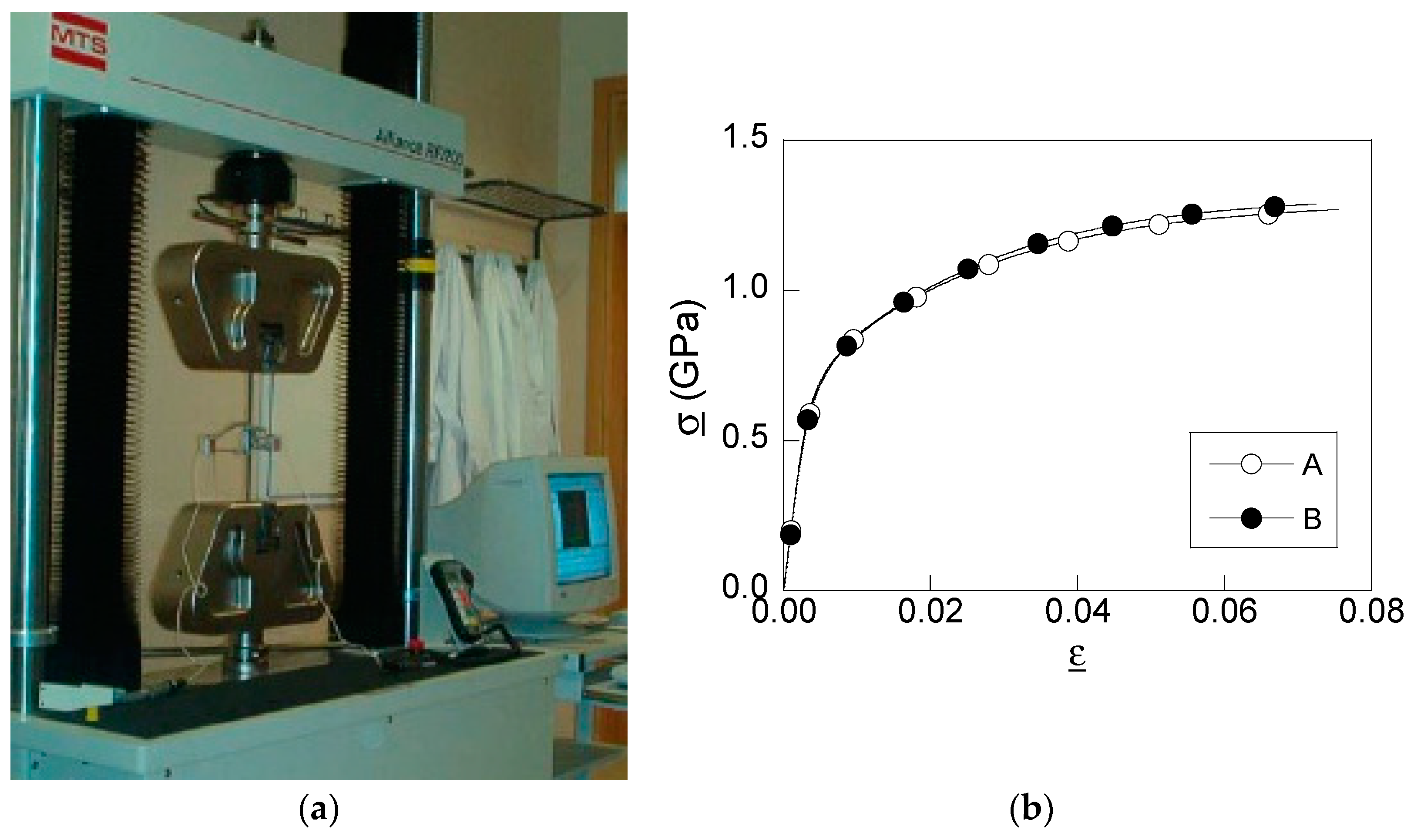
Considering the different strain histories of wires A and B, the hardening histories will be different as well. Thus, it is interesting to reveal the material properties and the evolution with drawing in both processes. To achieve this goal, a diverse conventional tension test up to fracture was carried out for each of the wires obtained at the end of the diverse drawing steps of both drawing processes. Samples of 300 mm length were tested for each drawing step (corresponding to wire-drawing processes A and B), applying a constant displacement rate of 2 mm/min with a universal test machine, MTS KN200 (MTS Inc., Eden Prairie, MN, USA) (Figure 2a). The sample displacements were measured with two MTS extensometers of 25 mm and 50 mm gauge lengths (MTS Inc., Eden Prairie, MN, USA). As a result of the tests, the experimental true stress vs. true strain curve was obtained (Figure 2b) and the mechanical properties of each cold-drawn wire were revealed. In this way, the Young modulus and the 0.2% offset yield strength of the wires obtained after each drawing step of both wire-drawing processes are included in Table 2. For the sake of clarity, in Figure 2b, only the master curves of the raw material (hot rolled bar) were shown. According to these values, a similar stiffness (Young modulus) and similar strength (0.2% offset yield strength) were obtained for both steels at the beginning of cold drawing (hot-rolled bar) and at the end (prestress steel wire).
From the experimental data obtained during testing, the evolution of the material hardening can be analyzed in terms of the material yield stress (σY) for both straining paths. For the sake of clarity, in Figure 3, the evolution of material yield strength (σY) with cumulative plastic strain is represented, together with the wire diameter reduction evolution for both cold-drawn wires.
As a result of the conformation process, the same increment in material strength was obtained in the prestressing steel wire due to strain-hardening, but in a different way depending on the strain history of the cold-drawn wire. Thus, on the one hand, the strength of wire type A is suddenly increased in the first step of wire-drawing, and later it is softly and linearly increased. On the other hand, wire B undergoes a soft reduction at first and, afterwards, the wire exhibits an almost linear strain-hardening up to the last step, where a heavy reduction is applied (generating a huge increment in the wire strength).
To reveal the stress and strain states after each step of the wire-drawing chains, a numerical simulation of both conforming processes was carried out using a commercial FE software (MSC. Marc 2022). Each die was modelled as a rigid body according to the requirements of such an element during drawing: no plastic strain and a low elastic strain [3]. Die geometry can be defined by two parameters: the half-angle of the die (α) and the bearing length (lz) [18]. In this paper, common values of such parameters when used in industry were considered, i.e., α = 7° and lz = d0 for all the drawing steps for dies using both drawing processes.
An axisymmetric case is suitable for simulations due to the revolute geometry of both the die and the wire [3]. The boundary conditions were applied as follows: (i) null displacement in the radial direction for the nodes placed at the wire symmetry axis due to the axisymmetric geometry, and (ii) a constantly increasing displacement applied to the nodes located at the front edge of the wire until reaching a value that places the wire completely out of the die. Drawing speed can be related to the slope of this linear variable displacement, so a commonly used drawing speed of 50 mm/s was considered in simulations. The FE analysis considered an elastoplastic constitutive model with large deformations and large strains with an updated lagrangian formulation for the steels. The von Mises yield surface, associated flow rule, and isotropic strain-hardening were included in simulations according to the master curve shown in Figure 2b. Different FE four-node quadrilateral meshes were analyzed to ensure an adequate mesh-convergence of the obtained results. Thus, a simple wire mesh was selected. The mesh was refined at a zone close to the point of contact between die and wire, with the size of the elements at the point of contact being lower than the size of elements placed at the wire core, where a coarser mesh is suitable.

3. Results

3.1. Residual Stress and Strain States

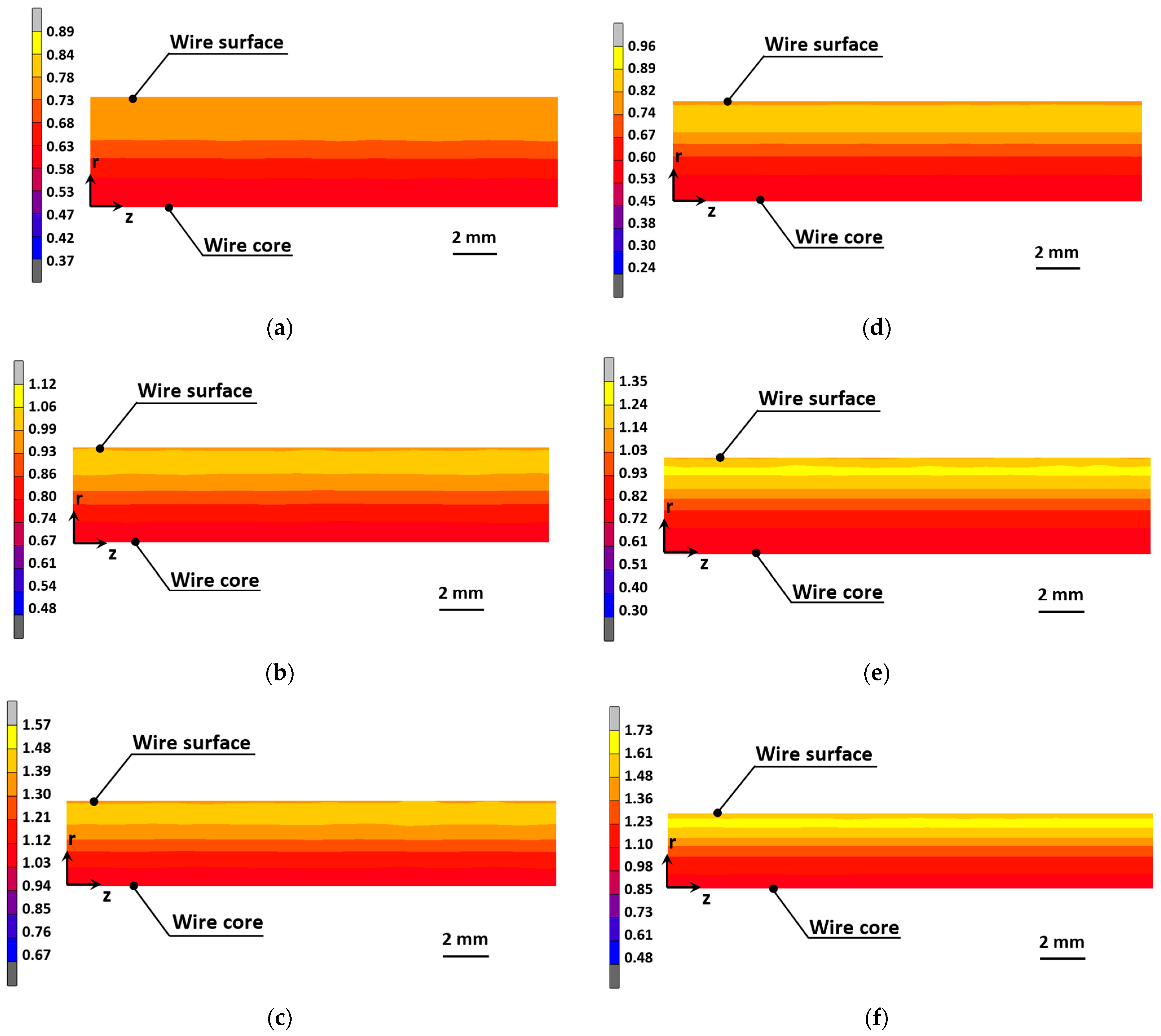
The numerical simulation of wire-drawing provides the stress and strain states after each step of the conforming process. To reveal the influence of the straining path on the HE of cold drawn wires, the analysis focused on the variables affecting hydrogen diffusion: the equivalent plastic strainP) and the hydrostatic stress (σ). In this way, Figure 4 shows the equivalent plastic strain fields for the equivalent cumulative strains reached during cold-drawing for A and B. Thus, for the wire-drawing process with fewer steps (wire-drawing A), the plastic strain distributions are more uniformly distributed in the radial direction for all drawing steps. However, the cold-drawing B exhibits a higher plastic strain near the wire surface (yellow zone in Figure 4) that appears even at the early stages of the process. Later, as the conforming process is developed, the cumulative plastic strain is increased.
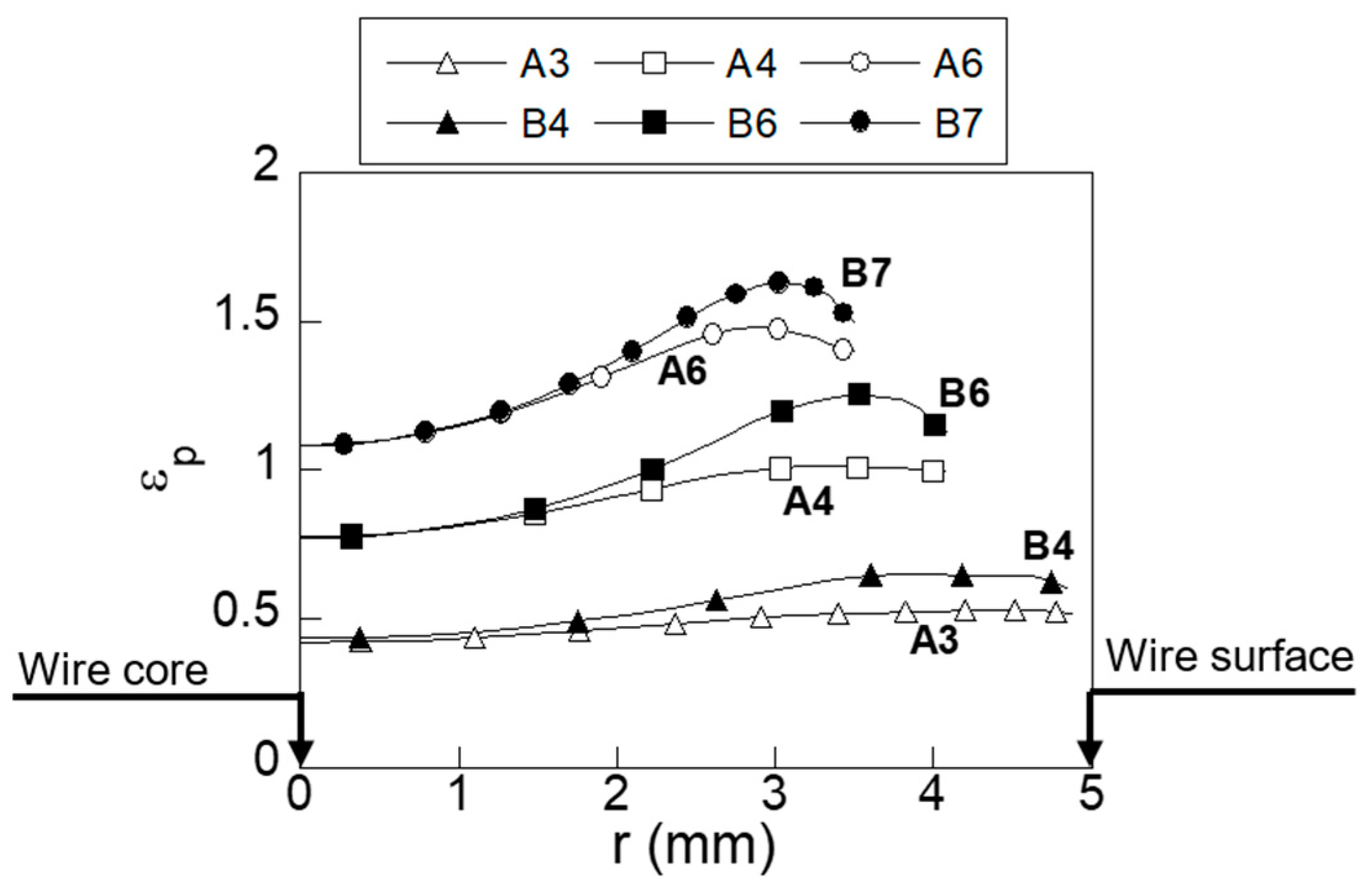
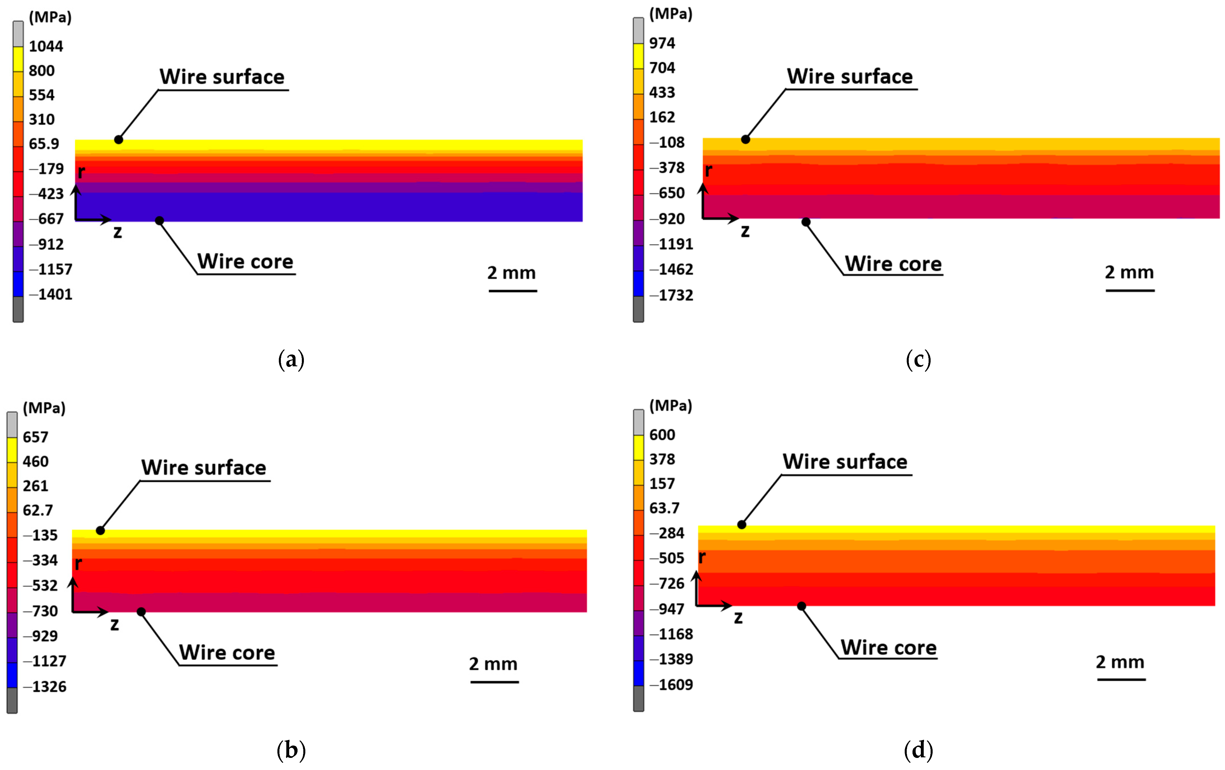
For a deeper analysis, Figure 5 shows the radial distribution of the equivalent plastic strain for two intermediate wires (3rd step of wire A vs. 4th step of wire B, and 4th step of wire A vs. 6th step of wire B) and for the final commercial prestressing steel wires (6th step of wire A vs. 7th step of wire B), cf. Figure 1. Plastic strains produced in the wire during the conformation process originate a stress state in the wire due to strain compatibility, which also affects the mechanical behavior of the wire during its life in service. In a similar way, Figure 6 shows the axial stress and hydrostatic stress fields generated after the wire-drawing A and wire-drawing B.
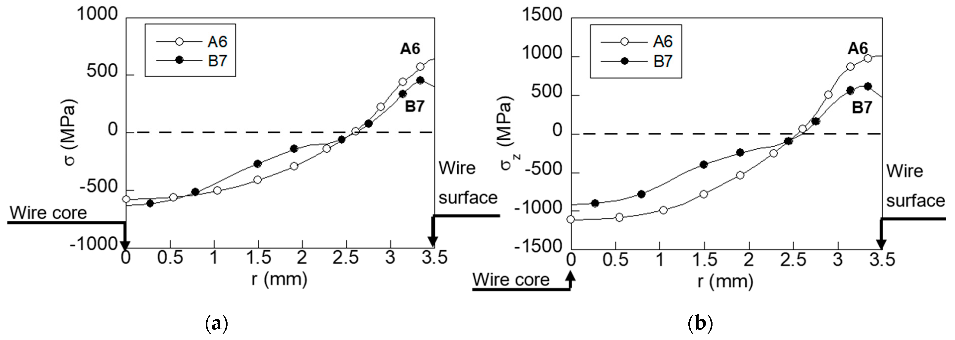
According to these results, high stress of a tensile nature appears at the wire surface for both wire-drawing processes with compressive stress located at the wire core. In Figure 7, the radial distribution of the variable representing the stress state in the hydrogen diffusion model (the hydrostatic stress) and the radial distribution axial stress are shown for the final drawing step in both processes.

3.2. Hydrogen Distributions

HE phenomena can be analyzed in terms of hydrogen diffusion through a material lattice. According to the model described in [43,44,45], hydrogen diffuses from the wire surface exposed to a hydrogenating environment towards the wire core. Equation (2) shows the dependence of hydrogen diffusion on the stress and strain states, which can be represented by: (i) the inward gradient of hydrostatic stress and (ii) the inward gradient of strain-dependent hydrogen solubility, respectively. This equation is a modified Fick type law, where two additional terms are included [40]:
C t = [ D C D C ( V H R T σ + K S ε ( ε ¯ P ) K S ε ( ε ¯ P ) ) ] ,
with R being the universal gases constant, VH the partial volume of hydrogen, T the absolute temperature and K the hydrogen solubility, which is linea rly dependent on equivalent plastic strains according to Equation (3) [43]
K = 1 + 4εp,
The steady-state solution of differential Equation (2) can be used to estimate the equilibrium concentration of hydrogen (Ceq). In this way, the long-time hydrogen accumulation in the metal can be obtained as follows:
C eq = C 0 K S ε ( ε ¯ P ) exp [ V H R T σ ] ,
where C0 is the equilibrium hydrogen concentration for a material that is free of stress and strain.
According to Equation (2), hydrogen is diffused from the wire surface towards the inner zones of the material, with a lower hydrogen concentration (negative inward gradient of hydrogen concentration), higher hydrostatic stress (positive inward gradient of hydrostatic stress) and higher hydrogen solubility (positive inward gradient of hydrogen solubility); in other words, towards zones with higher equivalent plastic strains considering the linear relation shown in Equation (3).
According to the hydrostatic stress and equivalent plastic strain fields shown in Figure 4 and Figure 6, respectively, the main changes are observed in the radial direction of the wire, with only minor variations being observed in the axial direction. Consequently, the /∂z derivatives are null, with z being the axial coordinate and, hence, the one-dimensional (1D) axisymmetric approach in the radial direction of the wire is suitable for a numerical simulation of the hydrogen diffusion in these wires. In this way, a general mathematical software was used to implement an FE numerical simulation of the axisymmetric boundary-value problem of diffusion assisted by stress and strain (Equation (2)). According to the Galerkin method, the element shape functions Ne(r) were used as trial and weighting functions [46]. In a similar way, the fields of hydrostatic stress σ(r) and equivalent plastic strain εP(r) were approximated with the shape functions as follows:
σ ( r ) = σ j N j ( r ) , ε P ( r ) = ε P j N j ( r ) ,
where j = 1, …, M corresponds to the number of nodes in the FE mesh, with M being the total number of nodes.
Considering the weak form of the weighted residual problem, a system of ordinary differential equations is obtained in terms of the hydrogen concentration Cj(t) at the FE mesh nodes as functions of time, as follows:
[ M i j ] { d C j d t } + [ K i j ] { C j } = { F i }   ( i , j = 1 ,   ,   M ) ,
where the components of the element matrices […] and the vector-columns {…} are
M i j = V N i N j d V ,
K i j = D ( ε P ) { N i N j [ ( V H R T σ + K S ε ( ε P ) K S ε ( ε P ) ) N i ] N j } d V ,
F i = J s S f N i d S ,
considering the boundary condition of hydrogen flux JS at the zone of the surface Sf.
The system of first-order differential Equation (6) is solved by applying the time-marching numerical scheme proposed for diffusion-type equations [46]. In this way, for a given m-th time interval [tm−1, tm], the nodal concentration values at the end of the time interval Cm can be related to the concentration at the initial time interval Cm−1, as follows:
( C m C m 1 ) ( M + θ   Δ t   K ) / Δ t + K C m 1 = F
where Δt = tmtm–1, and θ is a parameter that assures the stability of this time-marching scheme. The initial conditions are applied as the values of nodal concentration C0 at the first time interval (at m = 1). Later, the nodal concentration values for the following time interval Cm are obtained by solving the following equation in matrix form.
C m = C m 1 + ( M + θ   Δ t   K ) 1 ( F K C m 1 ) Δ t
For the sake of simplicity, the same mesh that was previously considered in the mechanical simulation of the wire drawing was used for the FE numerical simulation of the hydrogen diffusion, assisted by the stress and strain process considering linear trial functions for both space and time variables. In FE simulations, the following parameters were considered: temperature, T = 298 K; partial molar volume of hydrogen, VH = 2 cm3/mol [47].
Hydrogen diffusivity D is influenced by variations in chemical composition, microstructure and cumulative plastic strain. Thus, low values of diffusivity (D = 10–12 m2/s, [30]) are obtained at room temperature for heavily drawn wires with a high density of microstructural defects. In this way, for a hot-rolled bar, the hydrogen diffusivity is estimated as D(0) = 6.6 × 10⁻¹¹ m2/s [48] and, for a prestressing steel wire, it is estimated as D(6) = 4.99 × 10⁻¹² m2/s [30]. The numerical simulation of hydrogen diffusion assisted by stress and strain allows for one to obtain the hydrogen distributions for a long exposure time (Figure 8).

4. Discussion

4.1. Residual Stress and Strain States

While drawing, a huge stress concentration appears in the vicinity of the wire surface, causing plasticity and wire diameter reductions [3]. Thus, a non-uniform plastic strain distribution is produced in the wire at the end of each drawing step (Figure 5). The maximum plastic strain is placed near the wire surface within a heavily strained zone. This local effect vanishes for deeper points placed far from the wire skin. Thus, at the wire core, the plastic strains are similar to the values of the uniformly distributed plastic strain given by the theory of plasticity (Equation (1)).
Therefore, the main changes in plastic strain distribution are only expected to occur near to the wire surface. It should be noted that plastic strain leads to an increment in the material strength due to strain-hardening. Thus, taking this phenomenon into account, the surroundings of the wire surface, where cracks nucleate, will exhibit a higher strength or, in other words, a greater opposition to damage related to fatigue than the inner points of the wire. Nevertheless, at the microstructural level, the zone of high plastic strain is, in fact, a damage process zone with a high density of hydrogen traps where hydrogen is accumulated, causing microstructural fracture when the critical concentration of hydrogen is reached. Then, during fatigue loading, crack growth is produced due to the hydrogen damage that occurs in the plastic-strained process zone, as stated in previous works [49]. Thus, taking this into account, a wire-drawing process that produces a lower and more uniform strain state is adequate from the perspective of structural integrity, since this typ eof wire will reduce microstructural damage and, consequently, reduce the number of locations (hydrogen traps) at which hydrogen damage could take place.
As Figure 5 shows, the straining path modifies the radial distribution of plastic strain in the cold-drawn wires. Thus, wire B, which undergoes more drawing steps for a given wire diameter reduction, exhibits a higher and less uniform distribution of plastic strain than cold-drawn wire A. These differences, observed in the early steps of drawing, increase with the number of drawing steps.
Thus, the maximum plastic strain that is found at the end of the drawing process is increased by about 10% in the case of wire B compared to wire A. The inward gradient of the plastic strain influences the main stage of HE: hydrogen diffusion. Therefore, according to the results given in Figure 5, this parameter is progressively increased with drawing. In addition, the straining path clearly modifies the inward gradient of the plastic strain, since this parameter is two times greater in the final step of commercial wire B (B7) than it is in final wire A (A6). Thus, the way to obtain a more uniform plastic strain distribution is by considering a drawing chain with progressively decreasing wire diameter reductions to obtain the final required wire dimensions.
Figure 7 shows that the radial distribution of hydrostatic stress is clearly different depending on the straining path applied to the wire during the manufacturing process. In both cases, a tensile stress state appears in the vicinity of the wire skin (2.5 mm < r < 3.5 mm), whereas compressive stresses are placed at the inner points (r < 2.5 mm). At the tensile zone, the cold-drawn wire that undergoes a huge final reduction (wire B) has a lower stress state than wire A. Thus, at the wire surface, the hydrostatic stress of wire A is 60% higher than that in wire B. In addition, the distribution obtained in wire A progressively decreases with radial coordinate r, whereas the stress distribution of wire B has a more complex form, with a plateau in the compressive stress zone. This plateau originates from the huge reduction applied at the final step of the wire-drawing process, thereby causing a redistribution of the residual stress state.
Another interesting parameter for the analysis of hydrogen diffusion is the inward gradient of hydrostatic stress (Figure 7). Thus, the inward gradient of hydrostatic stress is positive for wire A, whereas the inward gradient of wire B is negative. These changes influence the behavior against the HE of the wires. In this way, the strain history modifies not only the plastic strain distribution but also the residual stress state at the end of the process.

4.2. Hydrogen Distributions

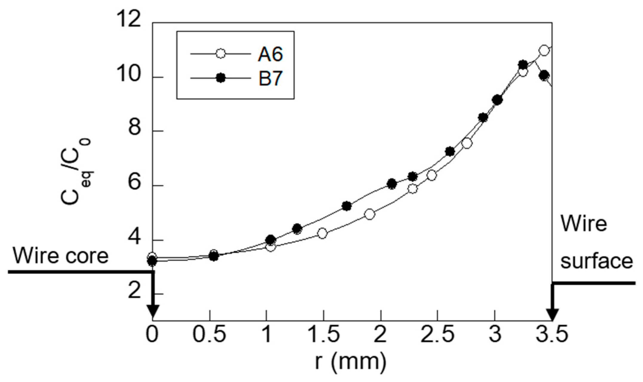
With regard to hydrogen distribution in wires A and B (Figure 8), the shapes of the radial distributions are similar to the hydrostatic stress distributions shown in Figure 7. In fact, the hydrogen distributions for both prestressing steel wires are similar, due to the actions of two competitive factors that take place during hydrogen diffusion. On the one hand, one of the driving forces for hydrogen diffusion is the inward gradient of equivalent plastic strain, which is lower in cold-drawn wire A than in wire B; consequently, hydrogen diffusion is enhanced for wire B. The other driving force for hydrogen diffusion, the inward gradient of hydrostatic stress, is negative in the case of wire A, which means that the diffusion process is slowed down. However, in the case of wire B, this driving force is positive within the range of 3.3 mm < r < 3.5 mm, showing again that hydrogen diffusion is enhanced for wire B. At the wire surface, the maximum potentially diffusible amount of hydrogen, obtained from the steady-state solution (Equation (4)), is lower in wire B than in wire A due to the lower hydrostatic stress state caused by the final reduction applied in wire B.
Therefore, according to this, during exposure to the hydrogenating environment, hydrogen will diffuse faster from the wire surface to the inner points in cold-drawn wire B than in cold-drawn wire A. Thus, more severe hydrogen damage could be expected in wire B. However, considering the steady state, i.e., for long periods of exposure to the aggressive environment, a reduction in the hydrogen content at the surface in wire B is achieved due to the lower stress that occurs in the zone near the wire surface (Figure 7).
Regarding the hydrogen concentration found during long exposure times, the comparison between both wires (A and B) shown in Figure 8 reveals that the most relevant difference regarding hydrogen concentration occurs near the wire skin, specifically at the surface (r = 3.5 mm), where the hydrogen concentration for wire A is 15% higher than for wire B. According to [30], microstructural damage appears close to the wire skin (x = 0.45 mm) in cold-drawn pearlitic steel wires, such as those analyzed in this paper.
Therefore, although the hydrogen concentration is slightly higher in the inner points placed within the range 1 mm < r < 2.5 mm (less important from the HE point of view) for wire B, in the most important surface areas, the hydrogen concentration is clearly higher in the case of wire A. Therefore, hydrogen damage could be considered less likely to occur in wire B.

5. Conclusions

The straining path applied during wire-drawing modifies both the plastic strains and the stress states of the wire. Such changes modify two of the driving forces for hydrogen diffusion: (i) the inward gradient of the strain-affected hydrogen solubility (∇K), which linearly depends on equivalent plastic strain, and (ii) the inward gradient of hydrostatic stress (∇σ). In this way, a straining path where the wire diameter reductions are progressively decreasing with drawing (wire A) produces more uniform radial distributions of the plastic strains, and lower distributions than those obtained with a straining path, where a huge final wire diameter reduction is carried out (wire B). Therefore, one of the driving forces for hydrogen diffusion (∇K) is lower in wire type A. In addition, in this type of wire, the other driving force (∇σ) is negative and, consequently, the hydrogen diffusion is slowed down and the hydrogen damage will develop with an increase in exposure to a hydrogenating environment.
However, for long periods of exposure to hydrogenating environments (steady-state situation), cold-drawn wires with a large final diameter reduction (steel B) exhibit a clear decrease in the hydrogen concentration at the surface (the most important zone from the fracture mechanics perspective), which is caused by a redistribution of the hydrostatic stress produced at the final stage of the process. In this way, the hydrogen supply to the inner points is reduced, and thus the risk of catastrophic failure under hydrogen embrittlement environmental conditions is lower.

Author Contributions

J.T. conceived and designed the analysis; M.L. performed the numerical calculations; both authors analyzed the data and wrote the paper. All authors have read and agreed to the published version of the manuscript.

Funding

The authors wish to acknowledge the financial support provided by the following Spanish Institutions: Ministry for Science and Technology (MCYT; Grant MAT2002-01831), Ministry for Education and Science (MEC; Grant BIA2005-08965), Ministry for Science and Innovation (MICINN; Grant BIA2008-06810), Ministry for Economy and Competitiveness (MINECO; Grant BIA2011-27870), Junta de Castilla y León (JCyL; Grants SA067A05, SA111A07 and SA039A08).

Institutional Review Board Statement

Not applicable.

Informed Consent Statement

Not applicable.

Data Availability Statement

Not applicable.

Conflicts of Interest

The authors declare no conflict of interest. With regard to the research funds, the different institutions providing financial support for the scientific research had no role in the design of the study; in the collection, analyses, or interpretation of data; in the writing of the present manuscript; and in the decision to publish the results.

References

  1. Toribio, J.; Ayaso, F.J.; Gonzalez, B.; Matos, J.C.; Vergara, D.; Lorenzo, M. Tensile fracture behaviour of progressively-drawn pearlitic steels. Metals 2016, 6, 114. [Google Scholar] [CrossRef] [Green Version]
  2. Överstam, H. The influence of bearing geometry on the residual stress state in cold drawn wire by the FEM. J. Mater. Process. Technol. 2004, 171, 446–450. [Google Scholar] [CrossRef]
  3. Toribio, J.; Kharin, V.; Lorenzo, M.; Vergara, D. Role of drawing-induced residual stresses and strains in the hydrogen embrittlement susceptibility of prestressing steels. Corros. Sci. 2011, 53, 3346–3355. [Google Scholar] [CrossRef]
  4. Ma, A.; Zhang, Y.; Dong, L.; Yan, H.; Fang, F.; Li, Z. Damage and fracture analyses of wire with off-center inclusion on multi-pass drawing under different back tensions. Eng. Fail. Anal. 2022, 139, 106512. [Google Scholar] [CrossRef]
  5. Toribio, J.; Lorenzo, M. On the use of multi-step dies for improving the performance against hydrogen embrittlement of cold drawn prestressing steel wires. Materials 2022, 15, 9085. [Google Scholar] [CrossRef]
  6. Wang, J.-H.; Lo, Y.-L.; Wang, H.-Y.; Tran, H.-C. Multi-objective optimization framework for five-pass wire-drawing process. Inter. J. Adv. Manuf. Technol. 2020, 107, 3049–3063. [Google Scholar] [CrossRef]
  7. Radionova, L.V.; Gromov, D.V.; Svistun, A.S.; Lisovskiy, R.A.; Faizov, S.R.; Glebov, L.A.; Zaramenskikh, S.E.; Bykov, V.A.; Erdakov, I.N. Mathematical modeling of heating and strain aging of steel during high-speed wire drawing. Metals 2022, 12, 1472. [Google Scholar] [CrossRef]
  8. Ma, A.; Cheng, J.; Wei, D.; Li, Q.; Fang, F.; Li, Z. Experiments and numerical analyses on splitting fracture of wire under multi-pass drawing. Eng. Fail. Anal. 2022, 134, 106035. [Google Scholar] [CrossRef]
  9. Park, H.; Kim, S.H.; Lee, W.J.; Ha, J.-W.; Kim, S.-J.; Lee, H.-J. Effect of wire-drawing process conditions on secondary recrystallization behavior during annealing in high-purity copper wires. Met. Mater. Int. 2021, 17, 2220–2229. [Google Scholar] [CrossRef]
  10. Suresh, S. Fatigue of Materials, 2nd ed.; Cambridge University Press: Cambridge, UK, 1998. [Google Scholar]
  11. Toribio, J.; Matos, J.C.; González, B.; Escuadra, J. Influence of residual stress fields on the fatigue crack propagation in prestressing steel wires. Materials 2015, 8, 7589–7597. [Google Scholar] [CrossRef] [Green Version]
  12. Toribio, J.; Matos, J.C.; González, B.; Escuadra, J. Fatigue crack growth in round bars for rock anchorages: The role of residual stress. Procedia Struct. Integrity 2016, 2, 2734–2741. [Google Scholar] [CrossRef] [Green Version]
  13. Toribio, J.; Lorenzo, M.; Vergara, D.; Aguado, L. Residual stress redistribution induced by fatigue in cold-drawn prestressing steel wires. Constr. Build. Mater. 2016, 114, 317–322. [Google Scholar] [CrossRef]
  14. Toribio, J.; Lorenzo, M.; Vergara, D.; Aguado, L. The role of overloading on the reduction of residual stress by cyclic loading in cold-drawn prestressing steel wires. Appl. Sci. 2017, 7, 84. [Google Scholar] [CrossRef] [Green Version]
  15. Roh, Y.-H.; Cho, D.; Choi, H.-C.; Yang, Z.; Lee, Y. Process condition diagram predicting onset of microdefects and fracture in cold bar drawing. Metals 2021, 11, 479. [Google Scholar] [CrossRef]
  16. Lodini, A. The recent development of neutronic techniques for determination of residual stresses. Radiat. Phys. Chem. 2001, 67, 227–233. [Google Scholar] [CrossRef]
  17. Sato, S.; Wagatsuma, K.; Suzuki, S.; Kumagai, M.; Imafuku, M.; Tashiro, H.; Kajiwara, K.; Shobu, T. Relationship between dislocations and residual stresses in cold-drawn pearlitic steel analyzed by energy-dispersive X-ray diffraction. Mater. Charact. 2013, 82, 152–160. [Google Scholar] [CrossRef]
  18. Toribio, J.; Lorenzo, M.; Vergara, D.; Kharin, V. Influence of the die geometry on the hydrogen embrittlement susceptibility of cold drawn wires. Eng. Fail. Anal. 2014, 36, 215–225. [Google Scholar] [CrossRef]
  19. Toribio, J.; Lorenzo, M.; Vergara, D. On the use of varying die angle for improving the resistance to hydrogen embrittlement of cold drawn prestressing steel wires. Eng. Fail. Anal. 2015, 47, 273–282. [Google Scholar] [CrossRef]
  20. Santana Martinez, G.A.; Qian, W.L.; Kyo Kabayama, L.; Prisco, U. Effect of process parameters in copper-wire drawing. Metals 2020, 10, 105. [Google Scholar] [CrossRef] [Green Version]
  21. Suliga, M.; Wartacz, R.; Hawryluk, M.; Kostrzewa, J. The effect of drawing in conventional and hydrodynamic dies on structure and corrosion resistance of hot-dip galvanized zinc coatings on medium-carbon steel wire. Materials 2022, 15, 6728. [Google Scholar] [CrossRef]
  22. Hwang, J.-K. Impact of die radius in a streamlined die during wire drawing. Appl. Sci. 2021, 11, 3922. [Google Scholar] [CrossRef]
  23. Radionova, L.V.; Lisovskiy, R.A.; Svistun, A.S.; Gromov, D.V.; Erdakov, I.N. FEM simulation analysis of wire drawing process at different angles dies on straight-line drawing machines. In Proceedings of the 8th International Conference on Industrial Engineering, ICIE 2022, Braga, Portugal, 28–30 June 2022; Lecture Notes in Mechanical Engineering. Radionov, A.A., Gasiyarov, V.R., Eds.; Springer: Cham, Switzerland, 2023; Volume 1, pp. 769–778. [Google Scholar]
  24. Stolyarov, A.; Polyakova, M.; Atangulova, G.; Alexandrov, S. Effect of die angle and frictional conditions on fine grain layer generation in multipass drawing of high carbon steel wire. Metals 2020, 10, 1462. [Google Scholar] [CrossRef]
  25. Tzou, G.-Y.; Chai, U.-C.; Hsu, C.-M.; Hsu, H.-Y. FEM simulation analysis of wire rod drawing process using the rotating die under Coulomb friction. MATEC Web Conf. 2017, 123, 00033. [Google Scholar] [CrossRef]
  26. Baumann, M.; Selbmann, R.; Milbrandt, M.; Kräusel, V.; Bergmann, M. Adjusting the residual stress state in wire drawing products via in-process modification of tool geometries. Materials 2021, 14, 2157. [Google Scholar] [CrossRef] [PubMed]
  27. Kim, J.-H.; Baek, C.-H.; Lee, S.-K.; Kang, J.-H.; Park, J.-H.; Ko, D.-C. Effect of a multiple reduction die on the residual stress of drawn materials. Materials 2021, 14, 1358. [Google Scholar] [CrossRef] [PubMed]
  28. Lin, H.-S.; Hsu, Y.-C.; Keh, C.-C. Inhomogeneous deformation and residual stress in skin-pass axisymmetric drawing. J. Mater. Process. Technol. 2008, 201, 128–132. [Google Scholar] [CrossRef]
  29. Toribio, J.; Lorenzo, M. Reduction of residual stresses in cold drawn pearlitic steel by a soft secondary wire diameter reduction. Metals 2023, 13, 433. [Google Scholar] [CrossRef]
  30. Toribio, J.; Elices, M. Influence of residual stresses on hydrogen embrittlement susceptibility of prestressing steels. Int. J. Solids Struct. 1991, 28, 791–803. [Google Scholar] [CrossRef]
  31. Lynch, S.P. Failures of structures and components by environmentally assisted cracking. Eng. Fail. Anal. 1994, 1, 77–90. [Google Scholar] [CrossRef]
  32. Mallick, A.; Das, S.; Mathur, J.; Bhattacharyya, T.; Dey, A. Internal reversible hydrogen embrittlement leads to engineering failure of cold drawn wire. Case Studies Eng. Fail. Anal. 2013, 1, 139–143. [Google Scholar] [CrossRef] [Green Version]
  33. Nakamura, S.-I.; Suzumura, K. Hydrogen embrittlement and corrosion fatigue of corroded bridge wires. J. Constr. Steel Res. 2009, 65, 269–277. [Google Scholar] [CrossRef]
  34. Vehovar, L.; Kuhar, V.; Vehovar, A. Hydrogen-assisted stress-corrosion of prestressing wires in a motorway viaduct. Eng. Fail. Anal. 1998, 5, 21–27. [Google Scholar] [CrossRef]
  35. Perrin, M.; Gaillet, L.; Tessier, C.; Idrissi, H. Hydrogen embrittlement of prestressing cables. Corros. Sci. 2010, 52, 1915–1926. [Google Scholar] [CrossRef]
  36. Toribio, J.; Kharin, V.; Vergara, D.; Lorenzo, M. Two-dimensional numerical modelling of hydrogen diffusion in metals assisted by both stress and strain. Adv. Mater. Res. 2010, 138, 117–126. [Google Scholar] [CrossRef]
  37. Panasyuk, V.V.; Ivanyts’kyi, Y.-L.; Hembara, O.V.; Boiko, V.M. Influence of the stress-strain state on the distribution of hydrogen concentration in the process zone. Mater. Sci. 2014, 50, 315–323. [Google Scholar] [CrossRef]
  38. Thompson, A.W.; Chesnutt, J.C. Identification of a fracture mode: The tearing topography surface. Metall. Trans. A 1982, 10, 379–405. [Google Scholar] [CrossRef]
  39. Costa, J.E.; Thompson, A.W. Hydrogen cracking in nominally pearlitic 1045 steel. Metall. Trans. A 1982, 13, 1315–1318. [Google Scholar] [CrossRef]
  40. Toribio, J.; Lancha, A.M.; Elices, M. Characteristics of the new tearing topography surface. Scr. Metall. Mater. 1991, 25, 2239–2244. [Google Scholar] [CrossRef]
  41. Toribio, J.; Lancha, A.M.; Elices, M. The tearing topography surface as the zone associated with hydrogen embrittlement processes in pearlitic steel. Metall. Trans. A 1992, 23, 1573–1584. [Google Scholar] [CrossRef]
  42. Enos, D.G.; Williams, A.J.; Scully, J.R. Long-term effects of cathodic protection of prestressed concrete structures: Hydrogen embrittlement of prestressing steel. Corrosion 1997, 53, 891–908. [Google Scholar] [CrossRef]
  43. Toribio, J.; Kharin, V. A hydrogen diffusion model for applications in fusion nuclear technology. Fusion Eng. Des. 2000, 51–52, 213–218. [Google Scholar] [CrossRef]
  44. Toribio, J.; Kharin, V. A generalised model of hydrogen diffusion in metals with multiple trap types. Philos. Mag. 2015, 95, 3429–3451. [Google Scholar] [CrossRef]
  45. Toribio, J.; Kharin, V. Hydrogen transport to fracture sites in metals and alloys: Multiphysics modelling. Struct. Integrity Proc. 2017, 5, 1291–1298. [Google Scholar] [CrossRef]
  46. Zienkiewicz, O.C.; Taylor, R.L. The Finite Element Method, 4th ed.; McGraw-Hill: London, UK, 1991; Volume 2. [Google Scholar]
  47. Hirth, J.P. Effects of hydrogen on the properties of iron and steel. Metall. Trans. A 1980, 11, 861–890. [Google Scholar] [CrossRef]
  48. Lillard, R.S.; Enos, D.G.; Scully, J.R. Calcium hydroxide as a promoter of hydrogen absorption in 99.5% Fe and a fully pearlitic 0.8% C steel during electrochemical reduction of water. Corrosion 2000, 56, 1119–1132. [Google Scholar] [CrossRef]
  49. Toribio, J.; Kharin, V. The effect of history on hydrogen assisted cracking: 1. Coupling of hydrogenation and crack growth. Int. J. Fract. 1997, 88, 233–245. [Google Scholar] [CrossRef]
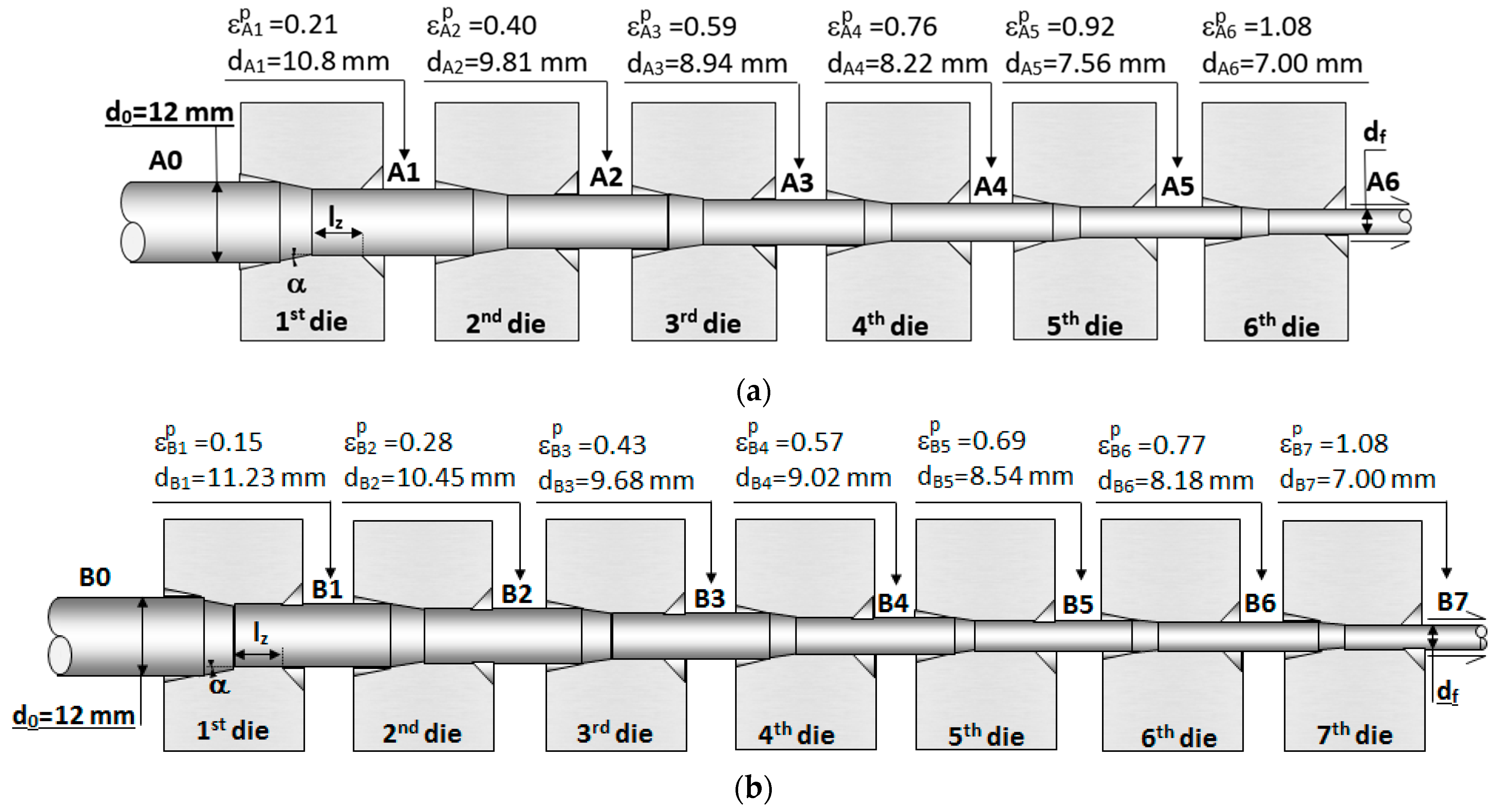
Figure 1. Schemes of the considered wire-drawing processes: (a) cold-drawn wire A and (b) cold-drawn wire B including the wire diameter, di, and the plastic strain, εpi.
Metals 13 01321 g001
Figure 2. Conventional tension test: (a) experimental set-up and (b) constitutive law (equivalent stress, σeq, and equivalent strain, εeq, curve) of both pearlitic steels, obtained experimentally from simple tensile tests.
Metals 13 01321 g002
Figure 3. Variation in the material yield strength (σY) and wire diameter reduction (Δd/d) during wire-drawing of both materials. Data obtained experimentally from conventional tensile tests.
Metals 13 01321 g003
Figure 4. Equivalent plastic strain fields during cold-drawing A: (a) after 3 steps, (b) after 4 steps, (c) at the final step, and during cold-drawing B: (d) after 4 steps, (e) after 6 steps, (f) at final step.
Metals 13 01321 g004
Figure 5. Equivalent plastic strain, εp, distribution for wires A and B for similar wire reductions.
Metals 13 01321 g005
Figure 6. Stress fields after drawing: (a) axial stress after cold-drawing A, (b) hydrostatic stress after cold-drawing A, (c) axial stress after cold-drawing B, (d) hydrostatic stress after cold-drawing B.
Metals 13 01321 g006
Figure 7. Radial distribution of (a) hydrostatic stress σ and (b) axial stress σz at the final step of cold-drawing wire A (A6) and wire B (B7).
Metals 13 01321 g007
Figure 8. Radial distribution of dimensionless hydrogen concentration (C/C0) at the final step of cold-drawing wires A and B for a long period (t→∞) of exposure to the hydrogenating environment.
Metals 13 01321 g008
Table 1. Chemical composition of the analyzed hot-rolled bars.
% C% Mn% Cr% Si% V% P% S% Al
Steel A0.8000.6900.2650.2300.0600.0120.0090.004
Steel B0.7890.6980.2710.2260.0780.0110.0050.003
Table 2. Mechanical properties of the analyzed cold-drawn steels.
Wire-Drawing AWire-Drawing B
E (GPa)σY (MPa)E (GPa)σY (MPa)
Initial194720202720
Step 12011110204840
Step 21871120204880
Step 31901118203950
Step 419012602031010
Step 529513302011090
Step 620715702011120
Step 7--2051580
Disclaimer/Publisher’s Note: The statements, opinions and data contained in all publications are solely those of the individual author(s) and contributor(s) and not of MDPI and/or the editor(s). MDPI and/or the editor(s) disclaim responsibility for any injury to people or property resulting from any ideas, methods, instructions or products referred to in the content.