Article

Use of Sn60Pb40 Solder in Resistance Element Soldering Technology

Institute of Technologies and Materials, Faculty of Mechanical Engineering, Slovak University of Technology in Bratislava, Námestie slobody 17, 812 31 Bratislava, Slovakia
*
Author to whom correspondence should be addressed.
Metals 2023, 13(7), 1313; https://doi.org/10.3390/met13071313
Submission received: 28 June 2023 / Revised: 18 July 2023 / Accepted: 20 July 2023 / Published: 22 July 2023
(This article belongs to the Special Issue Advanced Studies in Metal Joining)

Abstract

:
This work presents a new technology for joining dissimilar materials, Resistance Element Soldering (RES). This technology is fundamentally based on Resistance Element Welding (REW) technology; the difference is that the presented RES uses a bimetallic element composed of a hard Cu shell and a core made of Sn60Pb40 solder. The RES technology using the Cu/Sn60Pb40 bimetallic element was tested when joining a galvanized steel sheet (HX220BD-100MBO) to a thermoplastic (PMMA). The effect of the process parameters on the volume of the melted solder, the deformation of the element, and the structure of the soldered joint was investigated on the joints made. The final criterion for assessing the influence of the process parameters was the joint strength. Due to the low strength of PPMA, the maximum joint strength was determined on RES joints of galvanized steel sheet and aluminum. The results showed that, to ensure the joint strength at the level of the strength of the Sn60Pb40 solder used, a heat input of 952 J and a clamping force of 623 N are required. The mentioned parameters ensure the necessary conditions for the creation of a soldered joint with a galvanized steel sheet as well as the deformation of the bimetallic element to create a form-fit effect in the opening of the PMMA to create a mechanical connection.

1. Introduction

Resistance Element Welding (REW) is one of the progressive technologies for joining dissimilar materials [1]. The principle is based on the use of an element of a suitable shape, which is designed to create a combined metallurgical–mechanical joint between materials with different physical and mechanical properties. In practice, the technology has been applied mainly in the joining of steel and aluminum sheets in the production of car bodies [2,3,4,5,6]. The lap joint is created by an element that passes through a hole in the upper aluminum sheet and is welded to the lower steel sheet through resistance welding. The shape and dimensions of the shaft and head of the element ensure a form-fit connection with the aluminum sheet.
Currently, robotic welding systems using REW are designed in such a way that the positioning of the element occurs in the phase of perforating the aluminum sheet. In this case, the steel element also takes over the function of a punching tool. In addition to the most used combination of materials (steel/aluminum), REW was also tested when joining magnesium to steel [7,8,9,10], titanium to steel [11], aluminum to titanium [12], and metallic materials to non-metallics [13,14,15]. The effect of different types of adhesives implemented in REW technology on the joint properties was also verified [16,17].
The interest in REW is documented by extensive research and development in the field of innovation of the base technology. Paper [7], for example, reports the results of using the alternative technology of Resistance Rivet Welding (RRW), where an expansion rivet is used to join magnesium to steel. The authors of paper [18] describe innovative REW using an element that acquires its definitive shape only after being pressed into a hole in an aluminum sheet.
Element Arc Spot Welding (EASW) [19] offers a different method of joining steel sheets to aluminum using an element. It is a technology in which a hollow steel rivet is inserted into a prepared hole in an aluminum sheet. During the joining of the aluminum to the steel sheet, the hollow rivet is filled with weld metal using arc spot welding. This creates a weld joint between the steel sheet and the element.
Another proposal on the construction of the element is presented in paper [20]. In this case, a bimetallic element was used in REW, which consisted of a hard metal shell and a soft solder core. A shell made of Cu provides a form-fit connection, and a core made of a Sn-Pb alloy is responsible for the metallurgical joint. The advantage of this solution is that the joint is created at a significantly lower temperature than in standard REW. While the melting temperature of the steel element is around 1500°C, when using the bimetallic element with a core of Sn-Pb solder, the heating temperature at the joint is lower than 300°C. Since the metallurgical joint in this case is created on the principles of soldering and not welding as in original REW, a more suitable name for the mentioned method of joining is Resistance Element Soldering (RES). In this way, it is possible to join metallic materials (e.g., galvanized steel sheets) with materials with a low melting point or thermal decomposition (e.g., thermoplastics). The proposed solution thus expands the already known technological possibilities of joining metal materials with thermoplastics [21,22,23,24].
The presented work is aimed at verifying the suitability of using Sn60Pb40 solder in bimetallic elements for Resistance Element Soldering (RES) technology.

2. Materials and Methods

For the experiment of joining dissimilar materials through RES, bimetallic elements Cu/Sn60Pb40 were made. The bimetallic element (Figure 1) consisted of a shell (Cu tube) and a core (Sn60Pb40 solder).
The basic criterion in the selection of materials for the manufacturing of the bimetallic element was to ensure its two basic functions:
-
Metallurgical joint with the lower sheet;
-
Creation of conditions for a form-fit effect between the element and the upper material of the lap joint.
Sn60Pb40 has been used for several decades for soldering galvanized steel sheets and copper. It is characterized by a low liquid temperature (190 °C) and a short freezing range (7 °C) [25].
Copper tubes with an outer diameter of 6 mm and a wall thickness of 0.5 mm were used for the shell of bimetallic elements. The material had a strength of 238 MPa. Other properties of the materials used for the elements are listed in Table 1 and Table 2. The strength and deformation properties of the materials were obtained on the basis of a tensile test according to the EN ISO 6892-1 standard. The test was carried out on an Instron 1195 universal testing machine at a crosshead speed of 5 mm·min−1. The method of manufacturing bimetallic semi-finished products and finished elements is described in more detail in articles [26,27]. Unlike the results presented in paper [20], elements with modified geometry and dimensions were used to ensure better mechanical properties for RES joints. In addition, optimized parameters for casting semi-finished products and forming elements were used, so the elements were without imperfections (wrinkles in the shell, porosity, and eccentricity of the core).
Experimental RES technology was applied to the production of combined joints of galvanized steel sheet/thermoplastic (Figure 2). PMMA thermoplastic (trade name QUINN XT) with a thickness of 2 mm was used. The manufacturer declares a strength of 70 MPa and an elongation at break of 4% [29]. To place the bimetallic element, holes with a diameter of 6.1 mm and a recess of 1 mm with a diameter of 9.1 mm were pre-drilled into the pieces with dimensions of 30 mm × 100 mm (Figure 2).
From the galvanized steel sheet HX220BD-100MBO, with thickness of 0.8 mm, pieces with dimensions of 30 × 100 mm were made. The chemical composition and mechanical properties of the sheet are shown in Table 3 and Table 4. The thickness of the zinc coating was 15 μm.
Before resistance soldering, the bimetallic element was inserted into a pre-drilled hole in PMMA, the steel sheet was cleaned with acetone, and SF-601 liquid flux was applied to the cleaned surface. This flux is mainly intended for soldering with tin solders and for soldering copper, nickel, their alloys, and some steels [31].
ARO XMA 26kVA, AC 50 Hz (ARO S.A.S., Chateau-du-Loir, France) portable spot welding gun with ULB 1.4 control system (VTS Electro s.r.o., Bratislava, Slovakia) was used for resistance soldering. Electrodes made of Cu-Cr material with flat (FD-type) and semi-round (FB-type) front surfaces were used during the joining process. The use of the FD-type electrode for the element was motivated by ensuring an even distribution of pressure on the head of the element with a solder core. In addition, since the diameter of the flat electrode (16 mm) was larger than the diameter of the head of the element, the spattering of the molten solder should have been avoided. The semi-circular FB-type electrode from the side of the galvanized sheet enabled the concentration of the current at the point of contact and thus the rapid heating of the steel sheet to the soldering temperature. Miyachi Weld Checker MM-356 Bmeasuring device(Miyachi Technos Corporation, Arakawa-ku, Tokyo, Japan) was used to measure the real values of process parameters (current, voltage, and time).
The effect of the following was investigated on the manufactured samples of galvanized steel sheet/PMMA joints using bimetallic Cu/Sn60Pb40 elements:
-
Amount of heat on the volume of melted solder in the bimetallic elements;
-
Amount of heat on the deformation of elements;
-
Amount of heat on the thermal influence of the materials being joined;
-
Process parameters on the strength of the joint.
The following was also evaluated:
-
Structure of soldered joints (SEM and EDS);
-
Fracture surface morphology (SEM).
Table 5 shows the parameters of resistance heating during the soldering of experimental samples. The suitability of the used parameters was assessed primarily from the point of view of ensuring the primary requirements necessary to create a quality joint:
(a)
Melting the required amount of solder in the core of the bimetallic element;
(b)
Heating the galvanized steel sheet to the soldering (working) temperature;
(c)
Sufficient plastic deformation of the element.
Requirements (a) and (b) are necessary to create suitable conditions for wetting the galvanized steel sheet with molten solder. If requirement (c) is not met during resistance soldering, there will be no form-fit effect between the PMMA and the element. Sufficient plastic deformation of the element creates suitable conditions for generating the necessary compressive stress between the head of the element and the PMMA for fixing the joined sheets against mutual movement without breaking the PMMA in the place of the pre-drilled hole. The amount of necessary deformation will depend on the properties of the materials to be joined, the materials used to manufacture the element, and the purpose of using the joint.
During the soldering of the test samples, the power of the spot welding gun was set to 20%, which corresponded to a current (I) in the range of 6.14 to 6.22 kA and a voltage drop (U) of 0.51 to 0.57 V. The applied clamping force (F) 623 N was the same during the soldering of all test samples. By changing the soldering time (t) from 0.1 to 0.4 s, we created the conditions for heating the joint with a heat input (Q) of 352 to 1375 J. When calculating the heat input, relation (1) was used.
Q = U × I × t
where
  • Q—heat input (J);
  • U—voltage (V);
  • I—current (A);
  • t—heating (soldering) time (s).
The strength properties of the joints were determined through a tensile test according to the EN ISO 6892-1 standard. To assess the effect of process parameters on the maximum strength of the soldered joint between the element and the galvanized steel sheet, a new series of test samples was prepared in which the thermoplastic PMMA was replaced with an aluminum sheet because the strength of the PMMA was insufficient due to the pre-drilled hole. The parameters for making joints between galvanized steel sheet and aluminum sheet were the same as for making joints between galvanized steel sheet and PMMA (Table 5). The chemical composition and mechanical properties of the used 1 mm thick aluminum sheet are shown in Table 6 and Table 7.

3. Results and Discussion

In the experiment, the influence of the heat input on the joining process and the properties of the joints was primarily under review. A general view of the soldered joints from the face and reverse sides is shown in Figure 3 and Figure 4. A detailed view of the experimental joints is shown in Figure 5.
Using Sn60Pb40 solder and heating times of 0.1 and 0.2 s, no spatter of molten metal around the joint was observed (Figure 3a). The latter was observed in the steel/PMMA interface (Figure 5b) at longer heating times of 0.3 and 0.4 s. It appears that the main cause of liquid metal spattering was the uneven distribution of the applied pressure in the contact surface between the shaft of the element and the galvanized steel sheet, which occurred due to the failure to maintain the perpendicularity of the element to the surface of the steel sheet. Figure 5c documents the preservation of the protective Zn layer on the reverse side of the joint even at a higher heat input of 952 J at a heating time of 0.3 s, which is important in terms of ensuring the resistance of the galvanized steel sheet to atmospheric corrosion.
Figure 6 shows the cross-sections of the joints made with the bimetallic Cu/Sn60Pb40 element at different heating times. It is clear from the picture that the different heat inputs (Table 5) caused
(a)
Different volumes of the molten metal of the solder in the bimetallic element;
(b)
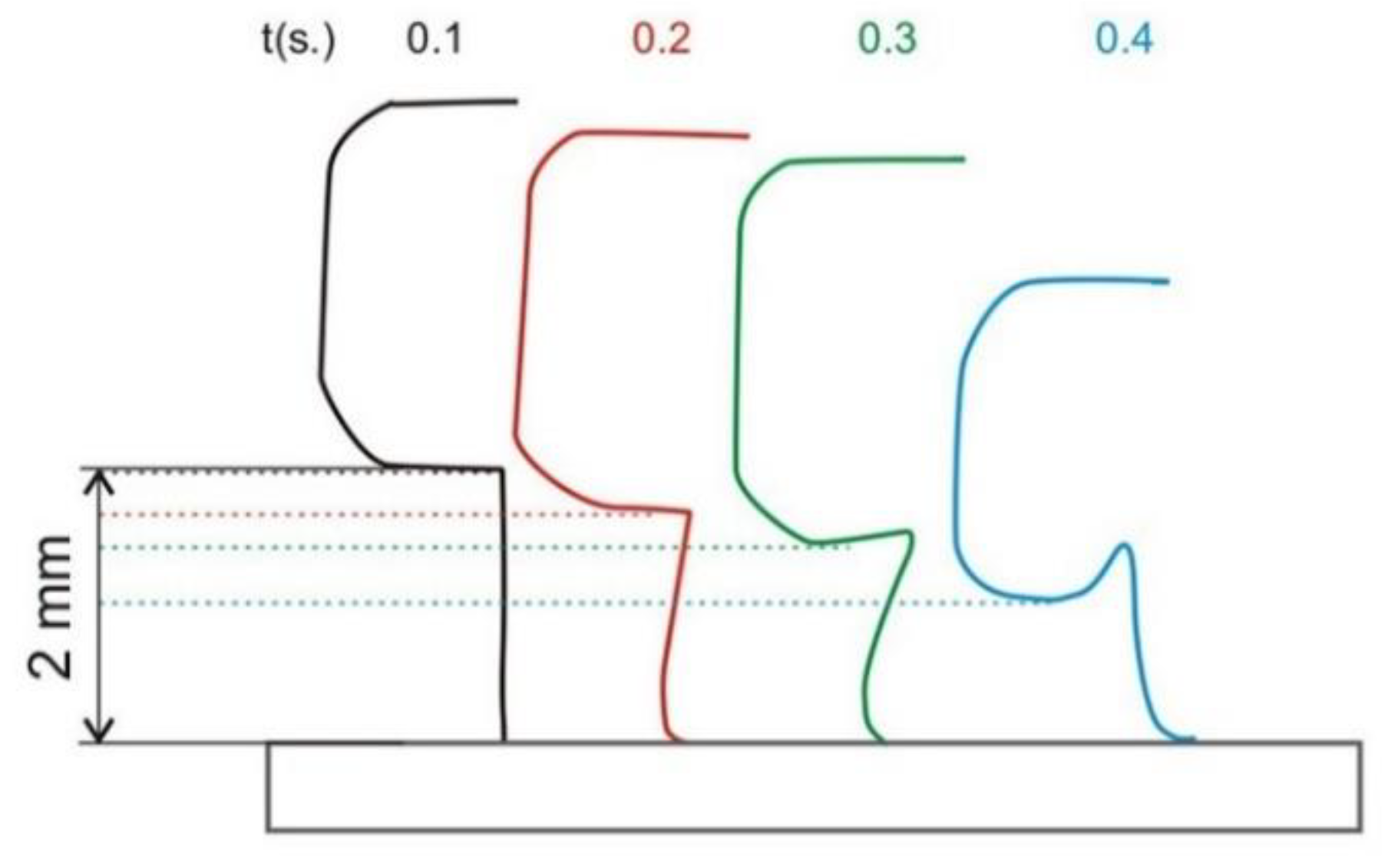
Different deformations of the bimetallic element.
(a)
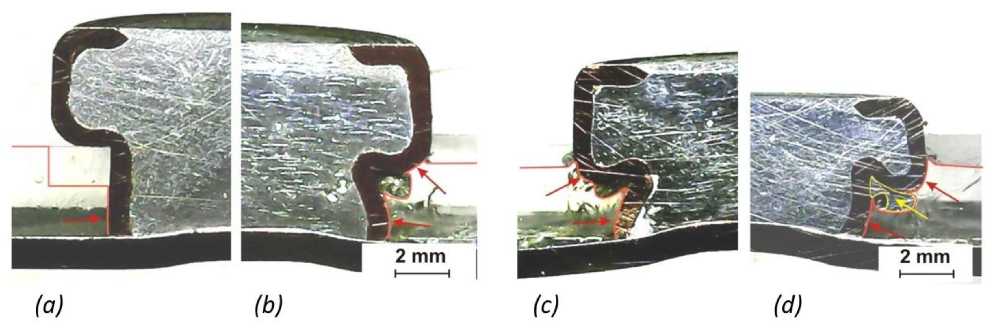
The amount of remelted solder in the core of the bimetallic element is shown in Table 8. The measurement was carried out through the method of image analysis on the cross-sections. The increase in the volume of the molten metal from 28% at a heating time of 0.1 s up to 80% at a heating time of 0.3 s corresponds to an increase in the heat input to the soldered joint (Table 5). At a heating time of 0.4 s, almost the entire volume of solder in the bimetallic element was already remelted. This state is already undesirable due to
  • The spattering of molten metal between the head of the element and the front surface of the electrode of the spot welding gun;
  • The possibility of creating a metallurgical joint between the element and the electrode.
(b)
The cross-sections of soldered joints made at different heating times with highlighted areas showing the force action between the element and the PMMA are shown in Figure 7.
With the shortest heating time (t = 0.1 s) and the lowest heat input to the soldered joint (Figure 7a), the selected clamping force, 623 N (Table 5), resulted in the insufficient deformation of the element in the pre-drilled hole in the PMMA. The force effect between the shell of the bimetallic element and the inner wall of the hole was created only at the end of the shaft of the element (marked by a red arrow). The fixation of the PMMA at the joint was not sufficient; on the prepared sample, it was possible to rotate the thermoplastic part freely around the soldered element. With a longer heating time (t = 0.2 s), a more significant deformation of the shaft of the element had already occurred (Figure 7b). The larger contact area (in the place of the shaft and partly also the element head) and the significant deflection of the deformed shaft ensured the necessary force effect for fixing the PMMA at the joint. A further increase in the heating time (t = 0.3 s) caused not only the deformation of the shaft but also partially that of the head of the element (Figure 7c). The shape and size change of the element was most pronounced when using the heating time of 0.4 s (Figure 7d). The larger deformation of the head of the element, which was pushed into the recess opening, is particularly noticeable. Furthermore, it can be noticed that the excessive overheating of the element caused a spattering of molten solder, which partially penetrated the area between the element and the PMMA (marked by a yellow arrow).
With the uniform distribution of the clamping force, the uniform deformation of the element occurred. At heating times of 0.1 to 0.3 s, the deformation was mainly manifested in the change in the length of the shaft of the element (Figure 8); at the heating time of 0.4 s, even the head of the element was significantly deformed (Figure 6d). At the lowest heat input during heating for 0.1 s, no deformation of the shaft of the element was noted. It remained at its original length of 2 mm. At the highest heat input during heating for 0.4 s, the shortening of the shaft of the element was the largest, decreasing from the original length of 2 mm to a length of 1.2 mm.
The deformation of the element is an important phenomenon in RES (REW) technology from the point of view of ensuring the form-fit connection between the element and the upper material [1]. The results showed that, from this point of view, not only is making the correct choice regarding the magnitude of the clamping force during resistance heating important but that the amount of heat supplied to the soldered joint is as well. In addition, it is necessary to ensure an even distribution of pressure on the head of the element. Otherwise, there will be an uneven deformation of the element (Figure 6b), which can have a negative effect on the spattering of the molten solder during resistance soldering and ultimately on the properties of the joint.
In neither case was there thermal or thermo-oxidative decomposition of the used thermoplastic in the heat-affected zone (in the contact area of the element and PMMA). The condition of the joining mode without an unwanted thermal influence of the basic materials was thus fulfilled.
Figure 9 shows the cross-sections of the soldered joints. Local porosity in the structure of the bimetallic element can be observed. The pores are in the middle part of the shaft only in the volume of solder that was remelted during joining. The occurrence of pores in the soldered joint was not observed on any sample. Since only defect-free semi-finished products (tested through X-ray radiation) were used for the manufacturing of the bimetallic elements, we can assume that the appearance of pores was caused by the insufficient degassing of the flux from the molten solder during resistance heating. Despite the extremely fast temperature increase and short cooling time when using resistance soldering [33], very good wetting of the base material (galvanized steel sheet) with the Sn60Pb40 solder from the bimetallic element can be seen at the joint (Figure 9a). Suitable wetting conditions were observed on the entire contact surface—in the middle (Figure 9b) as well as on the edges (Figure 9c).
A detail of the solder/galvanized steel sheet interface is documented in Figure 10. Element distribution maps as well as a line analysis show a relatively sharp interface between the solder and the base material (Figure 11 and Figure 12). In the transition area, we noticed the dissolution of the Zn protective layer of the galvanized steel sheet by the molten solder. The thickness of the Zn protective layer on the steel sheet thus decreased from the original 15 μm to approximately 1.5 μm. In addition, there was a change in the chemical composition in the transition area, which was caused by the diffusion of Sn from the solder into the Zn coating (Figure 12).
The structure of the solder was formed by primarily created grains rich in Pb and eutectic (a mechanical mixture of the solid solutions of Sn and Pb); see Figure 13. The observed structure corresponds to the Sn-Pb binary diagram. We noticed a more pronounced increase in the amount of Zn in the Sn60Pb40 solder structure in the area of the primarily created grains rich in Pb. In the base matrix of the solder (near the joint) formed by the eutectic, the proportion of Zn was zero (Figure 12).
The strength of the joints was determined through a tensile test. All the samples used were broken during the test by the fracture of the PMMA in the location that was weakened by the pre-drilled hole. The detail of the failure of the thermoplastic after the tensile test is documented in Figure 14.
To assess the maximum strength of the soldered joint, a new series of test samples was prepared. The PMMA was replaced by an aluminum sheet. The change in the heat input was again ensured only by changing the heating time from 0.1 to 0.3 s. Since significant solder spatter occurred already at the heating time of 0.3 s (Figure 15c), the heating time of 0.4 s was no longer used. Therefore, for the purposes of the tensile test, three series of samples were made.
The results of the tensile test are shown in Table 9. The failure occurred in all the samples in the soldered joint. Depending on the heating time, the average value of the joint shear strength ranged from 34 MPa, at a heating time of 0.1 s, to 53 MPa, at a heating time of 0.3 s. The results show that the strength of the joint using the bimetallic element is significantly influenced by the heating time and thus the heat input. Compared to the strength of the solder itself, which is 61.5 MPa (Table 2), the average maximum strength of the soldered joint at a heating time of 0.3 s was only slightly lower.
The strength of the RES joint is primarily determined by the type of solder, the size of the contact area between the element and the soldered sheet, and the heating of the sheet to the soldering temperature. For each shape and size of the bimetallic element, the heat input has some limit. It was found that, in the case of high heat input, when the volume of the remelted solder in the bimetallic element was close to 100%, there was an extreme spattering of the solder and thus a significant decline in the quality of the joint. The suitability of the recommended heating time of 0.3 s (Q = 952 J) was also confirmed by the results of the evaluation of the joint strength, when the obtained values were only slightly lower than the strength of the used solder. Contrariwise, a low heat input, e.g., a heating time of 0.1 s (Q = 352 J), was insufficient for heating the galvanized steel sheet to the working temperature, which was manifested by a low strength—the average strength value was only 64% of the strength of the joints obtained at a heating time of 0.3 s (Q = 952 J).
The fracture surfaces of the joints from the side of the galvanized steel sheet (made at different heating times) are shown in Figure 16. The images document the very good wetting of the base material by the Sn60Pb40 solder. The edges of the joints are clearly defined by the shell of the bimetallic element, which was pressed against the galvanized steel sheet during heating. As can be seen from the pictures, with the extension of the heating time (with an increasing heat input), the volume of solder that penetrated between the element and the galvanized steel sheet increased.
A detail of part of the fracture surface from the side of the galvanized steel sheet (heating time of 0.3 s) is shown in Figure 17. Maps of the distribution of the elements are shown in Figure 18. It can be seen from the pictures that the fracture propagated through the solder (an area with high Pb and Sn contents). The area with a dominant presence of Zn borders the inner diameter of the shell of the bimetallic element.
The shortcoming of the presented results is the relatively high dispersion of the joint strength values. This deficiency can be attributed to the sensitivity of the mechanical properties of the joints to solder spatter or to a rare occurrence of areas where suitable conditions for wetting the base material with the molten solder were not ensured (Figure 16c). The results show that the quality and strength of the joint is influenced, in addition to the process parameters and the quality of the bimetallic element, by the precise positioning of the element. This condition can be fulfilled by using a suitable jig, which ensures the perpendicularity of the element to the steel sheet during the making of the soldered joint.

4. Conclusions

The aim of the presented work was to verify the suitability of using Sn60Pb40 solder in Resistance Element Soldering (RES) technology. For this purpose, joints were made between galvanized steel sheets and thermoplastics (PMMA) using bimetallic elements, Cu/Sn60Pb40, with a shaft diameter of 6 mm. For an overall evaluation of the mechanical properties, joints between galvanized steel sheets and aluminum were made with the same type of elements. The following conclusions can be drawn from the achieved results:
1.
The heat input in the range of 352 to 1375 J (regulated by the heating time of 0.1 to 0.4 s) had a significant effect on the volume of the remelted solder in the core of the bimetallic element as well as on its total deformation:
a.
At the lowest heat input, the volume of the remelted solder represented only 28% (of the total volume of the core of the bimetallic element); at the highest heat input it was 95%. With a volume of the remelted solder greater than 80% (heat input of above 952 J), a spattering of Sn60Pb40 solder was observed at the joint location, which can negatively affect the overall properties of the joint.
b.
At a heat input of 352 J (heating time of 0.1 s), the required deformation of the bimetallic element did not occur for the creation of a form-fit connection with the PMMA. The fixation of the thermoplastic to the galvanized steel sheet at the joint was insufficient. The necessary deformation of the shaft of the bimetallic element only occurred when the heat input exceeded 700 J (heating time of 0.2 s). At the highest heat input of 1375 J (heating time of 0.4 s), the significant deformation of the head of the bimetallic element was observed.
2.
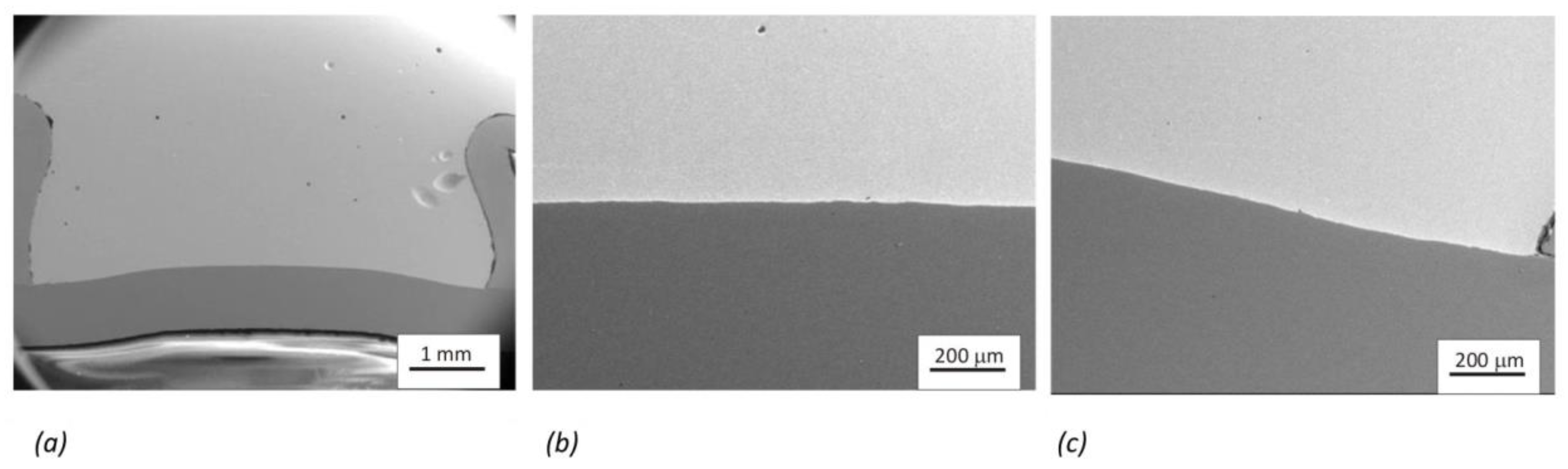
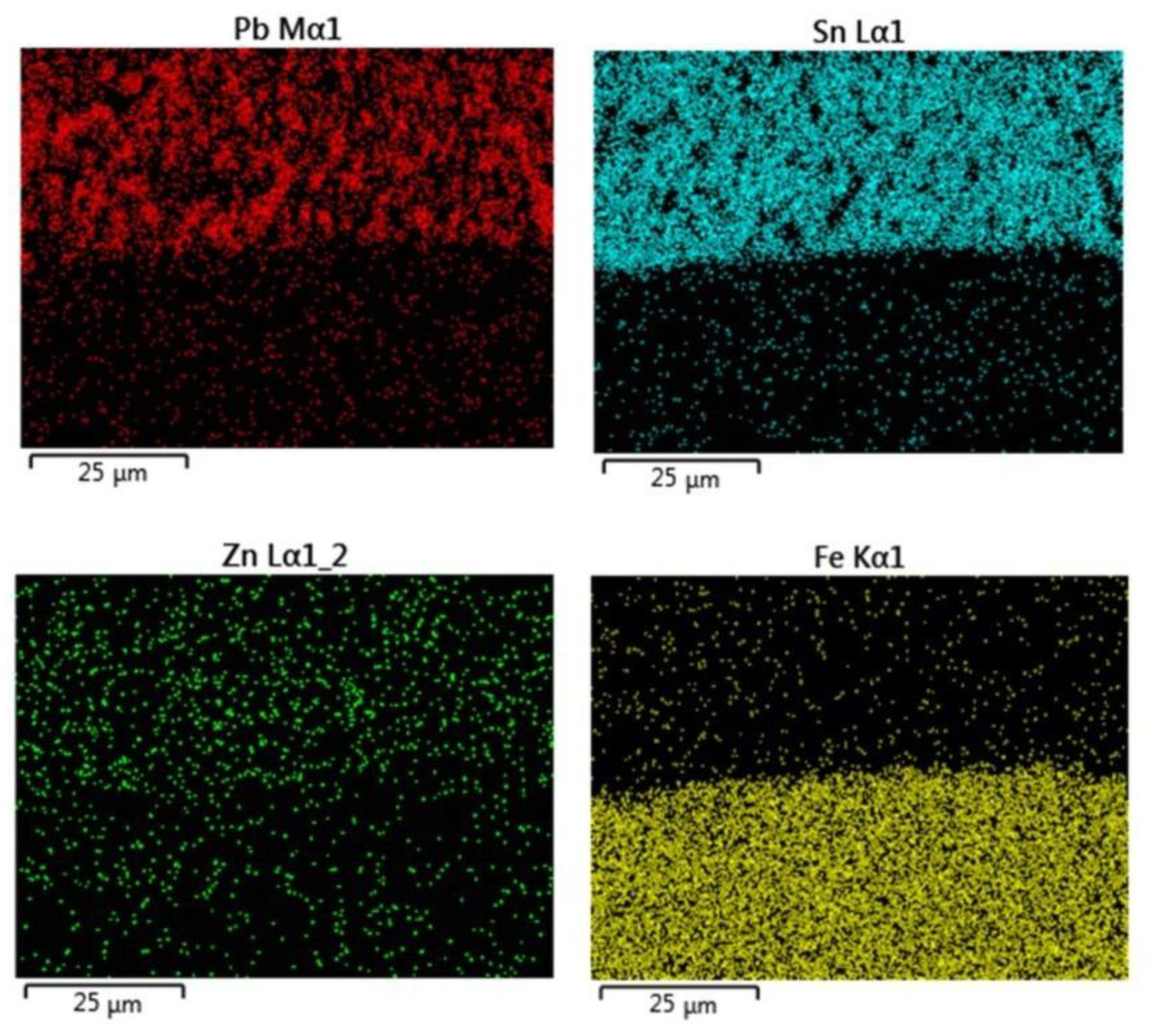
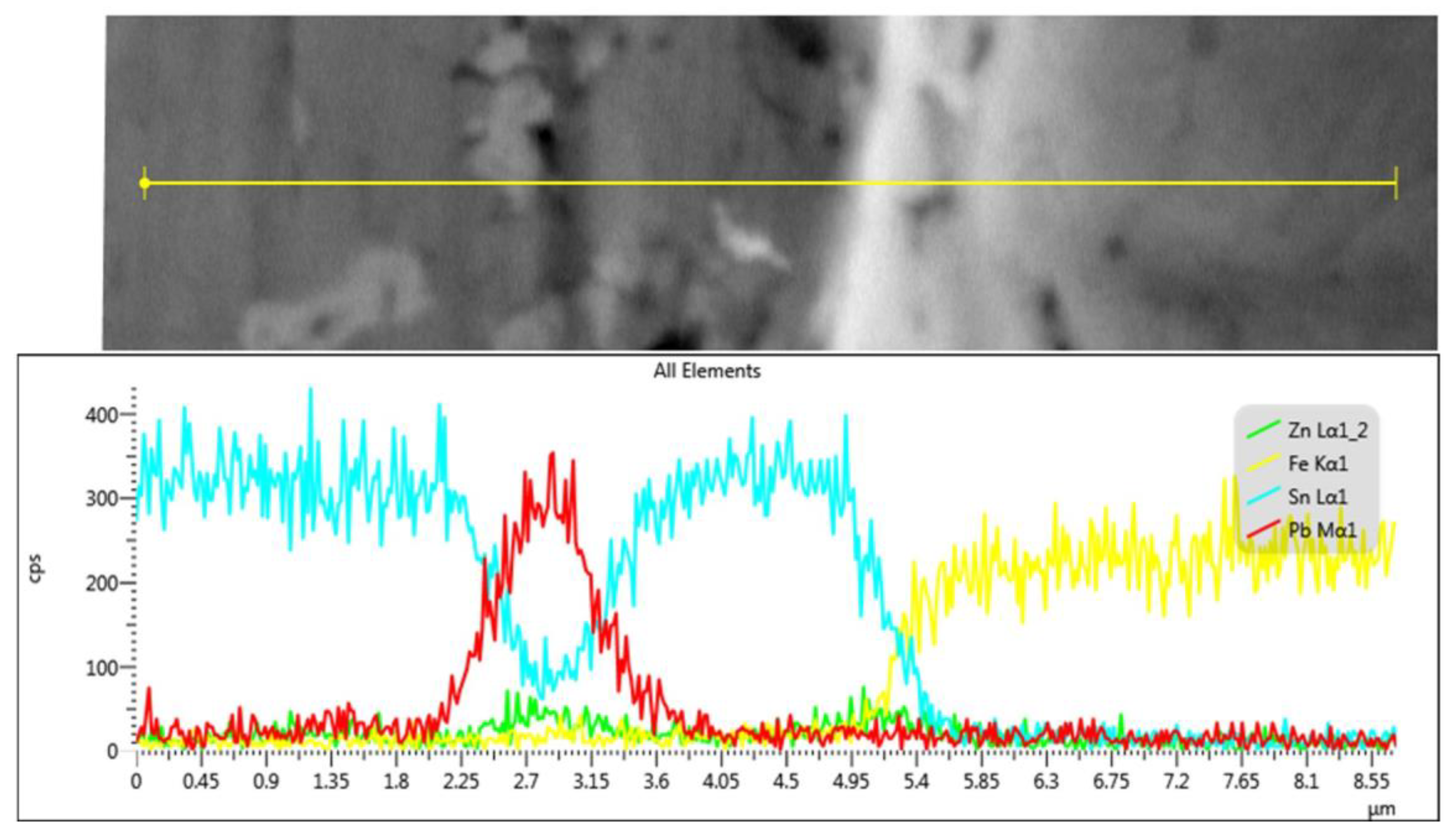
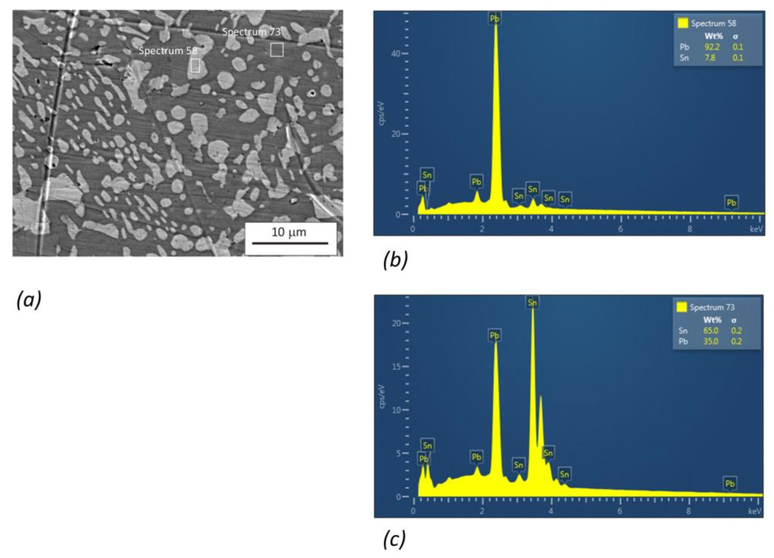
At a heat input of above 700 J (heating time of 0.2 s), a good wetting of the galvanized steel sheet with Sn60Pb40 solder was found, without thermal damage to the joined materials (the destruction of the protective Zn layer on the galvanized steel sheet or the thermal decomposition of the PMMA). Despite the rapid heating and short cooling time during resistance soldering, the dissolution of the Zn layer on the galvanized steel sheet by the solder and the diffusion of Sn from the solder into the Zn coating were observed. The thickness of the diffusion area from the side of the steel sheet reached a value of 1.5 μm. The solder structure formed by primarily created Pb grains and eutectic corresponds to the Sn-Pb binary diagram. A more significant increase in Zn in the Sn60Pb40 solder structure was observed in the area of primarily created grains rich in Pb. The appearance of pores in the structure of the solder arose because of its insufficient degassing during the cooling phase.
3.
From the results published so far, the type of coating on the joined material has a significant effect on the strength of the joints made with Sn-based solders [34,35,36]. The strength of the soldered joints between the galvanized steel sheet and PMMA using bimetallic elements, Cu/Sn60Pb40, exceeded the strength of the thermoplastic. The replacement test joints between the galvanized steel sheet and the aluminum were broken in the solder joint. Depending on the heat input during resistance soldering, the average strength varied from 34 MPa at 352 J (heating time of 0.1 s) to 53 MPa at 952 J (heating time of 0.3 s). The results showed that the heating time and thus the heat input have a significant effect on the strength of the joint using the bimetallic element, Cu/Sn60Pb40. Compared to the strength of the solder itself (61.5 MPa), the average value of the strength of the soldered joint was somewhat lower, which was probably caused by the sensitivity of the mechanical properties of the joints to local solder spatter and the occurrence of areas where the conditions for wetting the galvanized steel sheet with Sn60Pb40 solder were not met.
Based on the results, we assume that RES technology can be used wherever there is a requirement to join combined materials at low temperatures (up to 250°C). The soldered joint can be made on metal or ceramic materials, and any material that can withstand the soldering temperatures can be joined using RES technology. The technology is also suitable for joining sandwich materials, e.g., metal–plastic composites (MPCs).

Author Contributions

P.S. conceived, designed, and carried out the experiments as well as prepared and wrote the first and final text of the article in the native language. B.V. produced the bimetallic semi-finished products and samples for the tensile testing of the used materials as well as reviewed, edited, and translated the text. A.S. produced bimetallic elements, performed tensile tests, and reviewed the prepared text in the native language. Z.G. performed a metallographic analysis of the samples—electron microscopy and EDS analysis—and formatted the translated text. All authors have read and agreed to the published version of the manuscript.

Funding

This research received no external funding.

Data Availability Statement

Data sharing is not applicable to this article.

Acknowledgments

We would like to thank the supporters of the projects VEGA 1/0302/23, University Science Park of the Slovak University of Technology in Bratislava, ITMS code 26240220084, and Accord 2, ITMS code 313021BXZ1.

Conflicts of Interest

The authors declare no conflict of interest.

References

  1. Meschut, G.; Hahn, O.; Janzen, V.; Olfermann, T. Innovative joining technologies for multi-material structures. Weld. World 2014, 58, 65–75. [Google Scholar] [CrossRef]
  2. Baek, S.; Song, J.; Lee, H.-C.; Park, S.-Y.; Song, K.-H.; Lee, S.; Lee, S.-J.; Chen, C.; Kim, D. Robust bonding and microstructure behavior of aluminum/high-strength steel lap joints using resistance element welding process for lightweight vehicles: Experimental and numerical investigation. Mater. Sci. Eng. A 2022, 833, 142378. [Google Scholar] [CrossRef]
  3. Sun, Y.; Huang, R.; Zhao, H.; Chen, X.; Jiang, M.; Wu, L.; Chen, B.; Tan, C. Enhancement of resistance element welding of AA6061 to DP600 steel by using external magnetic field. J. Manuf. Process. 2022, 80, 347–358. [Google Scholar] [CrossRef]
  4. Niu, S.; Lou, M.; Ma, Y.; Li, Y. Study on the microstructure and mechanical performance for integrated resistance element welded aluminum alloy/press hardened steel joints. Mater. Sci. Eng. A 2021, 800, 140329. [Google Scholar] [CrossRef]
  5. Ling, Z.; Li, Y.; Luo, Z.; Feng, Y.; Wang, Z. Resistance Element Welding of 6061 Aluminum Alloy to Uncoated 22MnMoB Boron Steel. Mater. Manuf. Process. 2016, 31, 2174–2180. [Google Scholar] [CrossRef]
  6. Baek, S.; Go, G.Y.; Park, J.-W.; Song, J.; Lee, H.-C.; Lee, S.-J.; Lee, S.; Chen, C.; Kim, M.-S.; Kim, D. Microstructural and interface geometrical influence on the mechanical fatigue property of aluminum/high-strength steel lap joints using resistance element welding for lightweight vehicles: Experimental and computational investigation. J. Mater. Res. Technol. 2022, 17, 658–678. [Google Scholar] [CrossRef]
  7. Niu, S.; Lou, M.; Ma, Y.; Yang, B.; Shan, H.; Li, Y. Resistance rivet welding of magnesium/steel dissimilar materials. Mater. Lett. 2021, 282, 128876. [Google Scholar] [CrossRef]
  8. Manladan, S.; Yusof, F.; Ramesh, S.; Zhang, Y.; Luo, Z.; Ling, Z. Microstructure and mechanical properties of resistance spot welded in welding-brazing mode and resistance element welded magnesium alloy/austenitic stainless steel joints. J. Mater. Process. Technol. 2017, 250, 45–54. [Google Scholar] [CrossRef]
  9. Manladan, S.M.; Yusof, F.; Ramesh, S.; Zhang, Y.; Luo, Z.; Ling, Z. Resistance Element Welding of Magnesium Alloy/austenitic Stainless Steel. IOP Conf. Series Mater. Sci. Eng. 2017, 238, 012004. [Google Scholar] [CrossRef]
  10. Manladan, S.M.; Yusof, F.; Ramesh, S.; Fadzil, M. A review on resistance spot welding of magnesium alloys. Int. J. Adv. Manuf. Technol. 2016, 86, 1805–1825. [Google Scholar] [CrossRef]
  11. Ling, Z.; Li, Y.; Luo, Z.; Ao, S.; Yin, Z.; Gu, Y.; Chen, Q. Microstructure and fatigue behavior of resistance element welded dissimilar joints of DP780 dual-phase steel to 6061-T6 aluminum alloy. Int. J. Adv. Manuf. Technol. 2017, 92, 1923–1931. [Google Scholar] [CrossRef]
  12. Wang, S.; Li, Y.; Yang, Y.; Manladan, S.M.; Luo, Z. Resistance element welding of 7075 aluminum alloy to Ti6Al4V titanium alloy. J. Manuf. Process. 2021, 70, 300–306. [Google Scholar] [CrossRef]
  13. Troschitz, J.; Vorderbrüggen, J.; Kupfer, R.; Gude, M.; Meschut, G. Joining of Thermoplastic Composites with Metals using Resistance Element Welding. Appl. Sci. 2020, 10, 7251. [Google Scholar] [CrossRef]
  14. Schmal, C.; Meschut, G. Process characteristics and influences of production-related disturbances in resistance element welding of hybrid materials with steel cover sheets and polymer core. Weld. World 2020, 64, 437–448. [Google Scholar] [CrossRef]
  15. Zhang, Y.; Yang, Y.; Hu, J.; Luo, Z.; Bi, J.; Li, Y.; Su, J. Microstructure and joining mechanism of Al/CFRTP resistance element welded joints. J. Manuf. Process. 2022, 84, 251–259. [Google Scholar] [CrossRef]
  16. Manladan, S.; Zhang, Y.; Ramesh, S.; Cai, Y.; Luo, Z.; Ao, S.; Arslan, A. Resistance element weld-bonding and resistance spot weld-bonding of Mg alloy/austenitic stainless steel. J. Manuf. Process. 2019, 48, 12–30. [Google Scholar] [CrossRef]
  17. Holtschke, N.; Jüttner, S. Joining lightweight components by short-time resistance spot welding. Weld. World 2017, 61, 413–421. [Google Scholar] [CrossRef]
  18. Meinhardt, M.; Endres, M.; Graf, M.; Lechner, M.; Merklein, M. Analysing resistance element welding with upset auxiliary joining steel-elements under shear load. Procedia Manuf. 2019, 29, 329–336. [Google Scholar] [CrossRef]
  19. Suzuki, R.; Ryo, C. Aluminum-steel dissimilar robotic arc spot welding with auxiliary insert. Weld. World 2019, 63, 1733–1746. [Google Scholar] [CrossRef]
  20. Sejč, P.; Vanko, B.; Gábrišová, Z. REW Application Possibilities for the Production of Combined Metal—Plastic Joints. Manuf. Technol. 2021, 21, 682–690. [Google Scholar] [CrossRef]
  21. Modi, S.; Stevens, M.; Chess, M. Mixed Material Joining Advancements and Challenges. Cent. Automot. Res. 2017. Available online: http://www.cargroup.org/wp-content/uploads/2017/05/Joining-Whitepaper-Final_May16.pdf (accessed on 1 April 2023).
  22. Amancio-Filho, S.T.; Blaga, L.A. Joining of Polymer-Metal Hybrid Structures: Principles and Applications, 1st ed.; John Wiley & Sons Inc.: Hoboken, NJ, USA, 2018; ISBN 9781118177631. [Google Scholar]
  23. Huang, Y.; Gao, X.; Ma, B.; Zhang, Y. Interface Formation and Bonding Mechanisms of Laser Welding of PMMA Plastic and 304 Austenitic Stainless Steel. Metals 2021, 11, 1495. [Google Scholar] [CrossRef]
  24. Rodríguez-Vidal, E.; Sanz, C.; Lambarri, J.; Quintana, I. Experimental investigation into metal micro-patterning by laser on polymer-metal hybrid joining. Opt. Laser Technol. 2018, 104, 73–82. [Google Scholar] [CrossRef]
  25. Vianco, P. T: Solders Materials. Chapter 2. In Soldering Handbook, 3rd ed.; AWS: Seattle, DC, USA, 1999; ISBN 0-87171-618-6. [Google Scholar]
  26. Schrek, A.; Brusilová, A.; Sejč, P.; Vanko, B. Forming process simulation of bimetallic billet by extrusion for rew method. Acta Met. Slovaca 2021, 27, 210–213. [Google Scholar] [CrossRef]
  27. Schrek, A.; Vanko, B.; Sejč, P. Forming of a bimetallic element for the resistance element soldering method. J. Met. Mater. 2022, 74, 8–20. [Google Scholar] [CrossRef]
  28. Available online: https://www.kovot.sk/uploads/fck/file/Sn60Pb40_300.pdf (accessed on 15 March 2023).
  29. Available online: https://cdn1.idek.cz/dek/document/207270681-montazni-navody-plexiskla (accessed on 15 March 2023).
  30. Available online: http://www.steelnumber.com/en/steel_composition_eu.php?name_id=614 (accessed on 30 April 2023).
  31. Available online: https://www.vuz.sk/uploads/wysiwyg/katal%C3%B3gy/08_Spajky_ataviva_na_spajkovanie.pdf (accessed on 1 May 2023).
  32. Available online: https://www.alumeco.com/aluminium/plates/raw/en-aw-1050a/05-x-1000-x-2000-mm/p/390/3714 (accessed on 1 May 2023).
  33. Zhang, H.; Senkara, J. Resisitance Welding. Fundamentals and Applications, 2nd ed.; CRC Press: Boca Raton, FL, USA, 2012; ISBN 978-1-4398-5371-9. [Google Scholar]
  34. Bi, X.; Hu, X.; Li, Q. Effect of Co addition into Ni film on shear strength of solder/Ni/Cu system: Experimental and theoretical investigations. Mater. Sci. Eng. A 2020, 788, 139589. [Google Scholar] [CrossRef]
  35. Wang, H.; Hu, X.; Jiang, X. Effects of Ni modified MWCNTs on the microstructural evolution and shear strength of Sn-3.0Ag-0.5Cu composite solder joints. Mater. Charact. 2020, 163, 110287. [Google Scholar] [CrossRef]
  36. Li, Y.; Xu, L.; Jing, H.; Zhao, L.; Hao, K.; Han, Y. Study on the floating kinetics of graphene in molten Sn-based alloy based on in-situ observation of X-ray radiography. Compos. Part B 2022, 238, 109909. [Google Scholar] [CrossRef]
Figure 1. Bimetallic element: (a) construction and (b) finished product.
Metals 13 01313 g001
Figure 2. Assembly of joined parts.
Metals 13 01313 g002
Figure 3. General view of RES joints (steel/PMMA) with bimetallic element (Cu/Sn60Pb40) from the face (front side): (a) T5 (t = 0.1 s), (b) T10 (t = 0.2 s), (c) T15 (t = 0.3 s), and (d) T20 (t = 0.4 s).
Metals 13 01313 g003
Figure 4. General view of RES joints (steel/PMMA) with bimetallic element (Cu/Sn60Pb40) from the back (reverse side): (a) T5 (t = 0.1 s), (b) T10 (t = 0.2 s), (c) T15 (t = 0.3 s), and (d) T20 (t = 0.4 s).
Metals 13 01313 g004
Figure 5. Detailed view of RES joints (steel/PMMA) with bimetallic element (Cu/Sn60Pb40): (a) front side of T10 (t = 0.2 s), (b) front side of T15 (t = 0.3 s), (c) reverse side of T15 (t = 0.3 s).
Metals 13 01313 g005
Figure 6. Cross-sections of RES joints: (a) T5 (t = 0.1 s), (b) T10 (t = 0.2 s), (c) T15 (t = 0.3 s), and (d) T20 (t = 0.4 s).
Metals 13 01313 g006
Figure 7. Comparison of the form-fit effect between PMMA and the element at different heating times: (a) T5 (t = 0.1 s), (b) T10 (t = 0.2 s), (c) T15 (t = 0.3 s), and (d) T20 (t = 0.4 s).
Metals 13 01313 g007
Figure 8. Comparison of the effect of heating time on the deformation of the bimetallic element.
Metals 13 01313 g008
Figure 9. SEM images of a RES joint of a galvanized steel sheet with the core of a bimetallic element, Cu/Sn60Pb40, created at a heating time of 0.3 s: (a) general view, (b) detail from the center of the element, and (c) detail from the edge of the element.
Metals 13 01313 g009
Figure 10. Joint structure (heating time of 0.3 s).
Metals 13 01313 g010
Figure 11. Element distribution maps (see Figure 10).
Metals 13 01313 g011
Figure 12. Linear analysis of the distribution of elements across joint T15 (heating time of 0.3 s).
Metals 13 01313 g012
Figure 13. Structure of Sn60Pb40 solder (heating time of 0.3 s): (a) SEM image with marked areas for EDS analysis, (b) EDS analysis of “Spectrum 58”, and (c) EDS analysis of “Spectrum 73”.
Metals 13 01313 g013
Figure 14. Detail of sample T10 (t = 0.2 s) after tensile test.
Metals 13 01313 g014
Figure 15. General view of RES joints (steel/aluminum) with bimetallic element (Cu/Sn60Pb40) from the face (front side): (a) t = 0.1 s, (b) t = 0.2 s, and (c) t = 0.3 s.
Metals 13 01313 g015
Figure 16. General view of fracture surfaces (galvanized steel sheets) of joints made at different heating times: (a) t = 0.1 s, (b) t = 0.2 s, and (c) t = 0.3 s.
Metals 13 01313 g016
Figure 17. SEM image of a part of fracture surface on a galvanized sheet (soldering time of 0.3 s).
Metals 13 01313 g017
Figure 18. Element distribution maps (see Figure 17).
Metals 13 01313 g018
Table 1. Chemical composition of the solder [28].
MaterialSnPbCuZnAgSbBiCdSolidus/Liquidus
(%)(%)(%)(%)(%)(%)(%)(%)(°C)
Sn60Pb4059.5400.080.0010.10.20.10.002183/190
Table 2. Mechanical properties of the materials of the shell and the core of the bimetallic element.
MaterialDensity
(g·cm−3)
Yield Strength Re (MPa)Ultimate Tensile Strength Rm (MPa)Elongation at Break A (%)
Cu8.9655.523843.7
Sn60Pb408.5040.261.510.8
Table 3. Chemical composition of steel HX220BD-100MBO [30].
MaterialC
(%)
Si
(%)
Mn
(%)
P
(%)
S
(%)
Nb
(%)
Ti
(%)
Al
(%)
HX220BD-100MBO0.10.50.70.080.0250.090.120.1
Table 4. Mechanical properties of steel HX220BD-100MBO [30].
MaterialYield Strength
RP0.2 (MPa)
Ultimate Tensile Strength Rm (MPa)Elongation at Break
A80 (%)
HX220BD-100MBO220–280320–40032
Table 5. Process parameters of steel/PMMA-soldered joints.
SampleJoining ParametersNote
F (N)I (kA)U (V)t (s)Q (J)
T56236.180.570.1352Insufficient form-fit effect
T106236.140.570.2700None
T156236.220.510.3952Spatter of the solder
T206236.140.560.41375Spatter of the solder
Table 6. Chemical composition of aluminum AW-1050A [32].
Material Al
(%)
Si
(%)
Fe
(%)
Cu
(%)
Mn
(%)
Cr
(%)
Zn
(%)
Ti
(%)
AW-1050Arest0.250.400.050.010.010.070.05
Table 7. Mechanical properties of aluminum AW-1050A [32].
Material Yield Strength Rp0.2 (MPa)Ultimate Tensile Strength Rm (MPa)Elongation at Break
A (%)
AW-1050A75 ÷ 85105 ÷ 14520
Table 8. Effect of heating time on the volume of remelted solder Sn60Pb40 in the bimetallic element.
Heating Timet
(s)
Volume of Remelted Solder (%)
0.128
0.246
0.380
0.495
Table 9. Tensile test results for evaluating the strength of RES joints.
Sample NumberHeating Timet
(s)
Loading Force
Fmax (N)
Ultimate Tensile Strength Rm (MPa)Average Value of Tensile Strength Rm (MPa)Standard Deviation of Tensile Strength Rm (MPa)
10.184042.8034.038.10
273037.20
363032.10
449024.97
565033.12
10.289045.3543.216.68
2100050.96
364032.61
484042.80
587044.33
10.3122062.1753.409.58
2120061.15
390045.86
480040.76
5112057.07
Disclaimer/Publisher’s Note: The statements, opinions and data contained in all publications are solely those of the individual author(s) and contributor(s) and not of MDPI and/or the editor(s). MDPI and/or the editor(s) disclaim responsibility for any injury to people or property resulting from any ideas, methods, instructions or products referred to in the content.

