Abstract
The Cu-rich phase is a high-efficiency and ultra-stable precipitation-strengthening phase and has been widely used in many steels and alloys, especially in heat-resistant steels and alloys. Creep damage is accompanied with the coarsening of the second phase. In the present work, the calculation of phase diagrams (CALPHAD) method and elastic–plastic mechanics are coupled with the phase field (PF) approach to investigate the growth behavior and the accompanying stress/strain field evolution of nano-sized Cu-rich precipitates in an Fe-Cr-Ni-Cu medium-entropy alloy. The results show that creep strain is intensified with the coarsening of Cu-rich particles. The simulated size of Cu-rich particles is in good agreement previous experimental reports. The plastic strain tends to shear the Cu-rich phase when they are relatively fine (~<11 nm), and the size of the Cu-rich particles has a slight influence on the creep strain at this stage. In contrast, coarse Cu-rich precipitates (~>11 nm) are bypassed by the plastic strain due to the enhancing stress concentration around the interface, and the creep strain is rapidly aggravated with the growth of Cu-rich particles. The coarsening of Cu-rich particles will be retarded by the adjacent particles due to the overlapping of the diffusion zone, and hence the creep strain was reduced when crept for the same time. The retard effect will vanish when their distance is sufficiently long (~>60 nm). When the size of the Cu-rich particles is identical, the creep strain will be mitigated with elongation of the distance between two Cu-rich particles.
1. Introduction
Multi-principal alloys, including high-entropy alloys (HEAs) and medium-entropy alloys (MEAs), provide a brand-new perspective for material design. Particularly, Fe-Cr-Ni MEAs exhibit exceptional corrosion and oxidation resistance at elevated temperatures and have shown the capacity for application in fields of thermal power plants, pressure vessels, aerospace, etc. [1,2,3,4]. Precipitation strengthening is one of the main strengthening mechanisms, especially in heat-resistant alloys. Cu as a high-efficiency precipitation-strengthening element has been widely used in many steels and alloys including heat-resistant steels, reactor pressure vessel steels, high-strength low-alloy steels, etc. [5,6,7]. The hardening effect of the Cu-rich phase is founded in both ferrite/martensite matrices with body-centered cubic (BCC) structure and austenite matrices with face-centered cubic (FCC) structure. It is commonly recognized that Cu-rich phase precipitation in α-Fe is a complex crystal structure transformation process [8,9], while in the FCC matrix, the precipitation behavior of the Cu-rich phase is relatively simple. The only composition change takes place in the precipitation of Cu-rich particles in the FCC matrix, and no crystallographic transformation is observed [10,11]. The coherent relationship between the precipitates and the matrix was preserved during the entire creep process, even at later stages [12]. The creep strength of Fe-Cr-Ni-Cu MEAs is significantly enhanced due to many fine and well-dispersed Cu-rich particles. The strengthening effects of Cu precipitates are related to the size and number density of precipitates [13,14]. Herein, clarifying the deformation behavior arising from the coarsening of the Cu-rich phase is of great significance for revealing the precipitation-strengthening mechanism and enlightening the possibility to further enhance the strength of Cu-containing alloys. Due to the low strength of Cu-rich particles, dislocations tend to shear the particles when the size is relatively fine. With the coarsening of the Cu-rich phase, the moving dislocations will be hindered by the particle due to the enhancing strength and eventually bypass the obstacle by bending around it and then back straight to move [15]. Up to now, several efforts have been made to study the precipitation process of Cu-rich precipitates, including the size, shape, structural feature, composition of precipitates, etc. Isheim et al. [16] investigated the segregation of Ni and Mn at the interfaces of Cu-rich particles in a high-strength low-alloy steel. They believe that the growth and coarsening of the Cu-rich phase are retarded by the shell structure formed by the segregation of Mn and Ni due to the reduction in interfacial energy. However, the evolution of micro-stresses accompanied with the coarsening of Cu-rich particles and the consequent creep damage is rarely reported. Shim et al. [17] simulated the precipitation kinetics during aging in five austenitic heat-resistant steels using DICTRA software, an engineering tool for diffusion simulations in multicomponent alloys. Nevertheless, this method is unable to obtain the morphology features of the second phase as well as the stress evolution due to precipitation.
The PF method is increasingly used in the modeling and simulation of mesoscale microstructure evolution under different driving forces (e.g., compositional gradients, temperature, stress/strain, electric and magnetic fields) in materials science and physics including grain growth, sintering, solid state phase transformation, dislocation dynamics, fracture, damage, etc. [18,19,20,21]. By coupling with the CAPHAD database, the PF method can accurately investigate the sophisticated microstructure evolution in multicomponent alloys with reliable thermodynamic parameters. Zhu et al. [22] investigated the nucleation and growth behavior of BCC Cu precipitates followed by the BCC/9R phase transformation in an Fe-Cu alloy by the PF method. They found that the initial Cu concentration of precipitates are ageing-temperature-dependent and composition-dependent. Li et al. [23] simulated the coherent BCC/B2 microstructures in high-entropy alloys and the coarsening behavior of precipitates. Liu et al. [24] incorporated a CALPHAD database into a phase field framework to simulate the kinetics grain boundary microchemistry and precipitation behavior in high-strength Al-Zn-Mg-Cu alloys. Sun et al. [25] simulated the phase decomposition in thermal aging of an Fe-Cu-Mn-Ni-Al quinary system using the PF method coupled with CALPHAD thermodynamic databases. However, the accompanied stress/strain evolution has not been investigated.
In this work, the CALPHAD method and elastic–plastic mechanics are coupled with the PF approach to investigate the coarsening of Cu-rich phase as well as the accompanying stress/strain evolution in an Fe-Cr-Ni-Cu MEA during creep to reveal the mechanism of creep damage due to the coarsening of Cu-rich particles.
We designate contractions of tensors A = Aij and B = Bij over one and two indices as and . The transpose of A is AT, and I is the unit tensor.
2. Phase Field Model
2.1. Free Energy Formulation of Fe-Cr-Ni-Cu Alloy System
According to Landau’s theory of phase transformations, the Helmholtz free energy per unit volume of the Fe-Cr-Ni-Cu quaternary alloy system is formulated as [26]:
where Vm is the mole volume of the alloy, Fc is the mole Gibbs energy of the Fe-Cr-Ni-Cu alloy, which can be obtained by the CALPHAD method, Fe is the elastic energy density, and F▽ is gradient energy density.
Following the sub-regular solution approximation, Fc can be expressed as [27]:
where ci is the concentration obeying constraint and Gi is the Gibbs free energy of the pure element i with the FCC crystal structure. The subscripts i = 1, 2, 3, and 4 correspond to Fe, Cr, Ni, and Cu, respectively. EG is the excess free energy corresponding to the heat of mixing, and mgG is the magnetic contribution to the Gibbs free energy. R and T are the gas constant and the absolute temperature (K), respectively.
The function EG for a quaternary system is described as [28]:
where Li,j and Li,j,k are the binary and ternary interaction parameters, respectively.
The magnetic contribution to the Gibbs free energy mgG is formulated as [29]
where β is the atomic magnetic moment, τ = T/Tc is a dimensionless temperature, Tc is Curie temperature, p is a material constant, and p = 0.28 for the FCC phase. If β or Tc is negative, they should be revised as −β/3 and −Tc/3.
Assuming the simplest isotropic interfacial properties condition, the gradient energy can be expressed as [30]
where is the gradient energy coefficient [31]
where is the width of the interface and γi is the interfacial energy.
The elastic energy density is given as
where σ is the stress and εe is the elastic strain. According to Hook’s law
where C is the elastic stiffness tensor.
The elastic strain is given by
where is the eigenstrain due to precipitation, is the plastic strain, and is the total strain.
The eigenstrain is expressed as [32]
where is a smooth interpolation function and is the crystallographic misfit strain tensor, according to Vegard’s law [33]
where is the lattice mismatch of element i and I is the second-order identity tensor.
In the current investigation, we focused on the creep strain arising from the coarsening of the Cu-rich phase, while other factors such as dislocation motion and micro-voids are simplified and the phenomenological linear isotropic strain-hardening rule is used. The yield stress σy can be expressed as [34]
where H is the hardening modulus, σy0 is the initial yield stress, and is the equivalent plastic strain. Following the Prandtl–Reuss plastic flow rule [35]
where is Von Mises stress.
The stress/strain field can be obtained by solving the mechanical equilibrium equation
2.2. Kinetic Equation
The evolution of the concentration field is given by the Cahn–Hilliard equation [25,36]
where Lij is the matrix of Onsager coefficients and given by Darken’s equation [4]
where δij is the Kronecker delta and Di is the self-diffusion coefficient
where D0i is a frequency factor and Q0i is the activation energy.
The material properties P of the interface (elastic modulus E, yield strength σy, and hardening modulus H) are assumed to be the mix of the matrix Pm and Cu-rich phase PCu [37]
where is an equivalent concentration of Cu and can be defined as
where and are the equilibrium concentration of Cu in the matrix and Cu-rich particles, respectively.
3. Simulation Data
The chemical composition of the simulated MEA (wt. %) is Fe 50, Cr 22, Ni 25, and Cu 3. A two-dimensional rectangular domain with a size of 120 nm × 120 nm cubical grain is chosen as the simulated model. The finite element method was used to solve the coupled mechanical equilibrium Equation (16) and phase field Equation (17), and the grid size is 0.2 mm. The simulated alloy is crept at 973 K and 200 MPa for 1500 h. Four simulation cases were performed to investigate the effect of Cu-rich phase growth on the creep deformation of Fe-Cr-Ni-Cu MEA. The boundary conditions and initial conditions are shown in Figure 1, where n is the unit normal vector to the external boundary, Ji is the boundary flux, ki is the diffusion coefficient, and c0i is the initial concentration of element i. The lower left corner is fixed in all directions and the lower right corner is in the y direction to avoid rigid body motion. In Case 1, a single Cu-rich phase nucleus is prescribed at the center of the model, while in Cases 2~4, two nuclei with a distance of l0 were located on the vertical center line as the initial condition, and l0 = 15, 22.5, and 30 nm, respectively. The conditions of the four simulated cases are shown in Table 1.
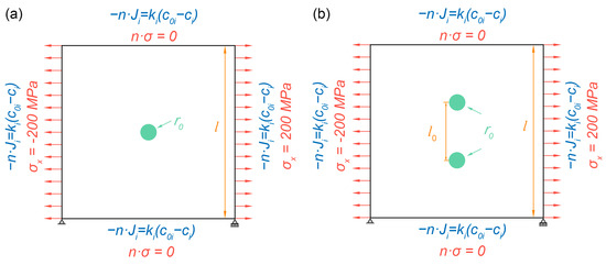
Figure 1.
Schematic of the simulation model and boundary conditions for simulated case 1 (a) and cases 2–4 (b).

Table 1.
Simulated cases.
It should be noticed that the practical grain size of the Fe-Cr-Ni-Cu alloy is around several hundreds of micrometers [3], which is much larger than the simulated area. Therefore, a convection boundary condition with the same diffusion rate as in the grain was assumed in all boundaries of the simulated area, which enables the elements in the simulated domain to be supplied or ejected to the surrounding bulk area.
The thermodynamic parameters of the Fe-Cr-Ni-Co alloy were taken from Thermo-Calc software, and mechanical properties of the matrix and Cu-rich particles were assumed to be identical with Sanicro 25 alloy and pure Cu, respectively, due to their similar chemical compositions. Values of parameters used in the PF model are summarized in Table 2. The finite element code COMSOL was utilized to solve the phase field and mechanical equations.
Table 2.
Values of parameters used in the PF model.
4. Simulation Results
The Cu-rich particles gradually coarsen with the aggregation of Cu atoms and the extrusion of Fe, Cr, and Ni atoms during the creep process. The composition distribution of the four simulated cases after being crept for 1500 h is shown in Figure 2.

Figure 2.
Morphology evolution of Cu precipitates (a,c,e,g) and concentration distributions along L1 line (b,d,f,h) in Case 1 (a,b), Case 2 (c,d), Case 3 (e,f) and Case 4 (g,h).
From Figure 2, an uphill diffusion mechanism is observed in the coarsening of the Cu-rich phase, and a Ni-rich shell embedded outside the Cu-rich core is formed which is supposed to impede the further coarsening of the Cu-rich phase [15,16]. The radii of the Cu-rich particles after being crept for 1500 h in the four simulated cases are 14.6, 12.0, 13.6, and 15.5 nm, respectively. In Cases 2~4, the radius of Cu rich particles is increasing with l0 due to the overlapping of the diffusion zone [45]. It should be noticed that the radius of Cu-rich particles in Case 4 is even larger than in Case 1. This is probably because the interface of the Cu-rich phase in Case 4 is very close to the boundary of the simulated domain, and the consumption of Cu atoms in the matrix around the Cu-rich particles can be easily supplied from the boundary. For comparison, the Cu concentration at 9 nm above the interface (defined as cCu = 0.5) of the upper Cu-rich particles in Case 4 (located on the upper boundary of the simulated domain) is 0.024; however, it is only about 0.011 at the same location in Case 1 (located in the matrix). The evolution of the Cu-rich phase radius and mean axial strain (defined as the mean axial elongation divided by the initial length of the simulated domain) in the four simulated cases are shown in Figure 3.

Figure 3.
Evolution of Cu-rich phase radius and mean axial strain as a function of creep time and the experimental data reported by Zhou et al. (a) and variation of mean axial strain with radius of the Cu-rich phases in the four simulated cases (b). Adapted with permission from Ref. [43]. Copyright 2020, Elsevier.
From Figure 3, the coarsening rate is relatively fast in the early stage of creep, and then it gradually slows down. The coarsening rates of Case 1 and Case 4 are the fastest, Case 3 comes third, and Case 2 is the slowest. It is also clear from Figure 3 that the coarsening rates of Cu-rich particles in Case 1 and Case 4 are almost identical before being crept for about 700 h, but since then, the coarsening rate in Case 4 gradually exceed Case 1, and the magnitude of the difference increased with creep time. This further illustrates that the distance between the two Cu-rich phase nuclei in Case 4 is large enough that their coarsening process is not affected by each other. Only in later stages of creep is the coarsening rate of Cu-rich particles in Case 4 accelerated, because the interface of Cu-rich particles is close to the boundary of the simulated domain and the Cu atoms’ depletion in the matrix around the Cu-rich particle can be supplied from outside of the boundary. It is also clear from Figure 3a that the simulated results, especially in Cases 1 and 4, are in good agreement with the experimental data reported by Zhou et al. [43] for the Sanicro 25 alloy, which has roughly the same chemical composition as the simulated alloy.
The creep strain of the simulated domain is gradually accumulated with the coarsening of Cu-rich particles. In the early stages of creep, the creep strain increases slowly even as the Cu-rich particles rapidly coarsen. Nevertheless, in the latter stages of creep, the creep strain aggravates promptly with the growth of Cu rich particles despite the coarsening rate of the Cu-rich particles gradually flattening. For a single Cu-rich particle in Case 1, the critical size of the Cu-rich particle for the change in the increasing rate of creep strain is around rc = 11 nm. Another notable phenomenon is that when there are two Cu-rich phase particles in the simulated grain, the creep strain increases with the increase in the distance between the two Cu-rich particles in same creep time; in contrast, the creep strain decreases with the increase in the distance between the two Cu-rich phase particles for same Cu-rich phase size.
5. Discussion
5.1. Influence of Cu-Rich Phase Growth on Creep Strain
The distribution of equivalent stress and equivalent plastic strain in Case 1 after creep for 500 h, 1000 h, and 1500 h, respectively, are shown in Figure 4.
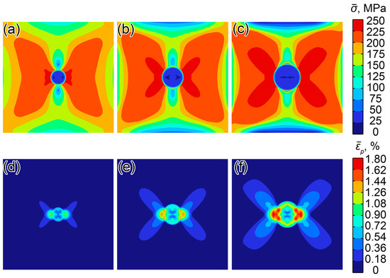
Figure 4.
Distribution of equivalent stress (a–c) and equivalent plastic strain (d–f) after creep for 500 h (a,d), 1000 h (b,e), and 1500 h (c,f) in Case 1.
A clear stress concentration is observed around the Cu-rich particle under axial tension. The stress in the Cu-rich particle is relatively low due to the low yield strength of Cu-rich phase. A butterfly-shaped stress contour is formed around the Cu-rich particle in the matrix and the maximum stress is located at the intersection of the horizontal center line of the simulated grain and the interface of Cu-rich particle, whereas stress in the matrix near the vertical center line is rather low. This is probably due to the low yield strength and strain-hardening capacity of the Cu-rich phase; the yield point of the Cu-rich phase is reached quickly under the action of applied axial tension, and a large amount of plastic strain is generated within it, which released the axial stress in the matrix near the vertical center line of the simulated grain.
It also can be seen from Figure 4 that the stress concentration on the interface of Cu-rich particles is aggravated with the coarsening of the Cu-rich phase, as is the corresponding plastic strain. After creep for 500, 1000, and 1500 h, the maximum stress on the interface of Cu-rich particles is 241.2, 248.5, and 254.3 MPa, respectively, and the maximum plastic strain is 1.11%, 1.46%, and 1.76%, respectively. The creep strain of the simulated grain is increased with the coarsening of Cu-rich particles, i.e., creep damage is aggravated with the coarsening of Cu-rich particles.
It also clear from Figure 4 that when the Cu-rich particle is relatively fine (t = 500 h), the plastic strain is majorly concentrated around the horizontal center line of the Cu-rich particle, and it seems that the Cu-rich particle is sheared by the plastic strain; in contrast, for large enough Cu-rich particles (t = 1500 h), the plastic strain is largely focused around the interface of Cu-rich particles due to the clear stress concentration around the interface and a plastic strain loop is formed, termed as the Orowan loop. In this mechanism, the plastic strain bends around the particle to bypass it. In the case of one single Cu-rich particle, the critical size of the transition of the interaction mechanism between dislocations and precipitates from shear to bypass is about rc = 11 nm. Zhou et al. [43] reported a very similar critical size of rc = 13 nm at the same temperature in the Sanicro 25 alloy, which has roughly the same chemical composition as the simulated alloy.
5.2. Influence of the Distance between Two Cu-Rich Particles on Creep Strain
Figure 5 shows the distribution of equivalent stress and equivalent plastic strain at r = 12 nm in simulated Cases 2~4. Because the Cu-rich particles are very soft, remarkably, plastic strain is generated in the particles, which will release the stress in the matrix at same axial position as the Cu-rich particles. In the three simulated cases, the plastic strain in the matrix at the same axial position as the Cu-rich particles is relatively low due to the low stress. However, the stress release effect of the soft Cu-rich particles weakens with the increase in the distance between the two Cu-rich particles, and the equivalent stress gradually increases.
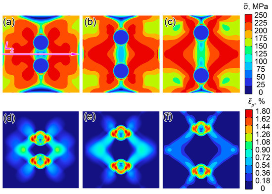
Figure 5.
Distribution of equivalent stress (a–c) and equivalent plastic strain (d–f) when r = 12 nm in Case 2 (a,d), Case 3 (b,e), and Case 4.
The distribution of equivalent stress along the L2 line in Figure 5a is shown in Figure 6. In simulated cases 2~4, the equivalent stresses at the center of the simulated grains are 78.2, 82.5, and 129.8 MPa, respectively, and the maximum stresses on this line are about 240.1, 235.2, and 231.0 MPa, respectively. With the increase in the distance between the two Cu-rich particles, the stress in the center of the two Cu-rich particles increases and hence bears more external loads. Meanwhile, the stress in the matrix at the same longitudinal position is decreases, as does the corresponding plastic strain, which results in a lower creep strain in the overall simulated grain. In other words, the stress distribution in the matrix in Case 4 is more homogeneous, which results in a lower plastic deformation in the overall simulated grain; in contrast, the stress in Case 2 is localized in the vicinity of the Cu-rich phase and a remarkable plastic is generated in this area. Hence, when the Cu-rich phase particles are of the same size, the larger their spacing is, the smaller the creep strain of the overall grains.

Figure 6.
Effect of distance between two Cu-rich phase particles on equivalent stress distribution along L2 line.
The above-mentioned discussion shows that nano-sized Cu-rich particles have a significant influence on the creep strength of Cu-containing MEAs. Both the size and distance between these particles play an important role in the strengthening effect of Cu-rich particles. Although creep strength may decrease when the distance between Cu-rich particles is shortened, the growth rate is also retarded due to the overlapping of the diffusion zone, eventually leading to a superior creep strength. These findings indicate that increasing nucleation sites is an effective method for improving the creep strength of Cu-containing MEAs.
6. Conclusions
In this study, the CALPHAD method and elastic–plastic mechanics are coupled with the PF method to investigate the coarsening of the Cu-rich phase in an Fe-Cr-Ni-Cu MEA during creep as well as the stress/strain evolution. The PF model developed in this study offers a powerful tool to investigate and design a precipitation process in steels and alloys. The simulated size of Cu-rich particles is in good agreement previous experimental reports. The findings of this investigation provide new insights to Cu precipitation in Cu-containing MEAs to optimize mechanical properties and some useful information to understand the mechanism of creep damage arising from the coarsening of the second phase.
The following conclusions have been drawn:
- (1)
- Creep strain of the simulated grain was intensified with the coarsening of Cu-rich particles. When the Cu-rich precipitates were relatively fine (~<11 nm), the plastic strain tended to shear the Cu-rich phase, and the size of the Cu-rich particle has a slight influence on the creep strain at this stage. However, for coarse Cu-rich precipitates (~>11 nm), the plastic strain will bypass them due to the enhancing stress concentration around the interface, and the creep strain is increased rapidly with the growth of Cu-rich particles.
- (2)
- The coarsening of Cu-rich particles will be retarded by the adjacent particles due to the overlapping of the diffusion zone, and hence the creep strain was reduced when creep occurred for the same time. The retard effect will vanish when the distance is sufficiently long (~>60 nm).
- (3)
- When the size of the Cu-rich particles is identical, the creep strain will be mitigated with elongation of the distance between the two Cu-rich particles, because a more homogeneous stress distribution is generated.
Author Contributions
J.G.: Investigation, writing—original draft, visualization. L.H.: Methodology, software. N.M.: Methodology, software, validation. X.F.: Conceptualization, methodology. Z.X.: Conceptualization, writing—review and editing, data curation. Y.H.: Conceptualization, supervision, resources. All authors have read and agreed to the published version of the manuscript.
Funding
This research was supported by the Key Project of Science and Technology in Shanxi Province of China (No. 20181101016).
Data Availability Statement
Data will be made available on request.
Conflicts of Interest
The authors declare no conflict of interest.
References
- Tang, L.; Jiang, F.Q.; Wróbel, J.S.; Liu, B.; Kabra, S.; Duan, R.X.; Luan, J.H.; Jiao, Z.B.; Attallah, M.M.; Nguyen-Manh, D.; et al. In situ neutron diffraction unravels deformation mechanisms of a strong and ductile FeCrNi medium entropy alloy. J. Mater. Sci. Technol. 2022, 116, 103. [Google Scholar] [CrossRef]
- Du, X.; Ma, X.; Ding, X.; Zhang, W.; He, Y. Enhanced high-temperature oxidation resistance of low-cost Fe–Cr–Ni medium entropy alloy by Ce-adulterated. J. Mater. Res. Technol. 2022, 16, 1466–1477. [Google Scholar] [CrossRef]
- Gao, J.; Xu, Z.; Fang, X.; He, J.; Li, W.; Du, X.; He, Y.; Jia, X.; Zhou, S. Enhancing creep resistance of aged Fe–Cr–Ni medium-entropy alloy via nano-sized Cu-rich and NbC precipitates investigated by nanoindentation. J. Mater. Res. Technol. 2022, 20, 1860–1872. [Google Scholar] [CrossRef]
- Fu, A.; Liu, B.; Li, Z.; Wang, B.; Cao, Y.; Liu, Y. Dynamic deformation behavior of a FeCrNi medium entropy alloy. J. Mater. Sci. Technol. 2022, 100, 120–128. [Google Scholar] [CrossRef]
- Kan, L.; Ye, Q.; Shen, Y.; Wang, Z.; Zhao, T. Co-precipitation of nanosized Cu and carbides improving mechanical properties of 1 GPa grade HSLA steel. Mater. Sci. Eng. A 2022, 859, 144211. [Google Scholar] [CrossRef]
- Xiao, B.; Xu, L.; Cayron, C.; Xue, J.; Sha, G.; Logé, R. Solute-dislocation interactions and creep-enhanced Cu precipitation in a novel ferritic-martensitic steel. Acta Mater. 2020, 195, 199–208. [Google Scholar] [CrossRef]
- Zhang, Y.; Liu, L.; Han, J.; Yang, J.; Luan, J.; Jiao, Z.; Liu, C.T.; Zhang, Z. Irradiation-induced solute trapping by preexisting nanoprecipitates in high-strength low-alloy steel. Mater. Sci. Eng. A 2022, 849, 143510. [Google Scholar] [CrossRef]
- Liu, S.; Rong, X.; Guo, H.; Misra, R.; Jin, X.; Shang, C. Reinforced Cu precipitation strengthening by matrix transformation from martensite to austenite in high-strength low-alloy steel. Mater. Sci. Eng. A 2021, 825, 141783. [Google Scholar] [CrossRef]
- Wang, J.; Enomoto, M.; Guo, H.; Shang, C. First-principles study on the equilibrium shape of nanometer-sized body-centered cubic Cu precipitates in ferritic steels. Comput. Mater. Sci. 2020, 172, 109351. [Google Scholar] [CrossRef]
- Wang, X.; Li, Y.; Chen, D.; Sun, J. Precipitate evolution during the aging of Super304H steel and its influence on impact toughness. Mater. Sci. Eng. A 2019, 754, 238–245. [Google Scholar] [CrossRef]
- Xi, T.; Zhang, X.; Yin, X.; Yang, C.; Yang, K. Interfacial segregation and precipitation behavior of Cu-rich precipitates in Cu-bearing 316LN stainless steel after aging at different temperatures. Mater. Sci. Eng. A 2021, 805, 140571. [Google Scholar] [CrossRef]
- Li, Y.; Wang, X. Precipitation behavior in boundaries and its influence on impact toughness in 22Cr25Ni3W3CuCoNbN steel during short-term ageing. Mater. Sci. Eng. A 2021, 809, 140924. [Google Scholar] [CrossRef]
- Fu, W.; Li, C.; Di, X.; Fu, K.; Gao, H.; Fang, C.; Lou, S.; Wang, D. Refinement mechanism of nanoscale Cu-rich precipitates by Mo addition and its effect on strength-toughness of Cu-bearing low carbon high strength steel. Mater. Sci. Eng. A 2022, 849, 143469. [Google Scholar] [CrossRef]
- Sun, H.; Li, D.; Diao, Y.; He, Y.; Yan, L.; Pang, X.; Gao, K. Nanoscale Cu particle evolution and its impact on the mechanical properties and strengthening mechanism in precipitation-hardening stainless steel. Mater. Charact. 2022, 188, 111885. [Google Scholar] [CrossRef]
- Li, Y.; Wang, X. Strengthening mechanisms and creep rupture behavior of advanced austenitic heat resistant steel SA-213 S31035 for A-USC power plants. Mater. Sci. Eng. A 2020, 775, 138991. [Google Scholar] [CrossRef]
- Isheim, D.; Gagliano, M.S.; Fine, M.E.; Seidman, D.N. Interfacial segregation at Cu-rich precipitates in a high-strength low-carbon steel studied on a sub-nanometer scale. Acta Mater. 2006, 54, 841–849. [Google Scholar] [CrossRef]
- Shim, J.-H.; Kozeschnik, E.; Jung, W.-S.; Lee, S.-C.; Kim, D.-I.; Suh, J.-Y.; Lee, Y.-S.; Cho, Y.W. Numerical simulation of long-term precipitate evolution in austenitic heat-resistant steels. Calphad 2010, 34, 105–112. [Google Scholar] [CrossRef]
- Chen, L.-Q.; Zhao, Y. From classical thermodynamics to phase-field method. Prog. Mater. Sci. 2022, 124, 100868. [Google Scholar] [CrossRef]
- Levitas, V.I. Phase transformations, fracture, and other structural changes in inelastic materials. Int. J. Plast. 2021, 140, 102914. [Google Scholar] [CrossRef]
- Tourret, D.; Liu, H.; Llorca, J. Phase-field modeling of microstructure evolution: Recent applications, perspectives and challenges. Prog. Mater. Sci. 2022, 123, 100810. [Google Scholar] [CrossRef]
- Bui, T.Q.; Hu, X. A review of phase-field models, fundamentals and their applications to composite laminates. Eng. Fract. Mech. 2021, 248, 107705. [Google Scholar] [CrossRef]
- Zhu, J.; Zhang, T.; Yang, Y.; Liu, C. Phase field study of the copper precipitation in Fe-Cu alloy. Acta Mater. 2019, 166, 560–571. [Google Scholar] [CrossRef]
- Li, J.; Li, Z.; Wang, Q.; Dong, C.; Liaw, P. Phase-field simulation of coherent BCC/B2 microstructures in high entropy alloys. Acta Mater. 2020, 197, 10–19. [Google Scholar] [CrossRef]
- Liu, C.; Garner, A.; Zhao, H.; Prangnell, P.B.; Gault, B.; Raabe, D.; Shanthraj, P. CALPHAD-informed phase-field modeling of grain boundary microchemistry and precipitation in Al-Zn-Mg-Cu alloys. Acta Mater. 2021, 214, 116966. [Google Scholar] [CrossRef]
- Sun, Y.Y.; Zhao, Y.H.; Zhao, B.J.; Wenkui, Y.; Xiaoling, L.; Hua, H. Phase-field modeling of microstructure evolution of Cu-rich phase in Fe-Cu-Mn-Ni-Al quinary system coupled with thermodynamic databases. J. Mater. Sci. 2019, 54, 11263–11278. [Google Scholar]
- Biner, S.B. Programming Phase-Field Modeling; Springer International Publishing: Cham, Switzerland, 2017. [Google Scholar]
- Li, W.; Chen, X.; Yan, L.; Zhang, J.; Zhang, X.; Liou, F. Additive manufacturing of a new Fe-Cr-Ni alloy with gradually changing compositions with elemental powder mixes and thermodynamic calculation. Int. J. Adv. Manuf. Technol. 2018, 95, 1013–1023. [Google Scholar] [CrossRef]
- Hillert, M.; Qiu, C. A thermodynamic assessment of the Fe-Cr-Ni-C system. Met. Trans. A 1991, 22, 2187–2198. [Google Scholar] [CrossRef]
- Hillert, M.; Jarl, A. A model for alloying in ferromagnetic metals. Calphad 1978, 2, 227–238. [Google Scholar] [CrossRef]
- Javanbakht, M.; Levitas, V.I. Athermal resistance to phase interface motion due to precipitates: A phase field study. Acta Mater. 2023, 242, 118489. [Google Scholar] [CrossRef]
- Malik, A.; Odqvist, J.; Höglund, L.; Hertzman, S.; Ågren, J. Phase-Field Modeling of Sigma-Phase Precipitation in 25Cr7Ni4Mo Duplex Stainless Steel. Metall. Mater. Trans. A 2017, 48, 4914–4928. [Google Scholar] [CrossRef]
- Chatterjee, S.; Schwen, D.; Moelans, N. An efficient and quantitative phase-field model for elastically heterogeneous two-phase solids based on a partial rank-one homogenization scheme. Int. J. Solids Struct. 2022, 250, 111709. [Google Scholar] [CrossRef]
- Zhang, K.; Wang, J.; Huang, Y.; Chen, L.-Q.; Ganesh, P.; Cao, Y. High-throughput phase-field simulations and machine learning of resistive switching in resistive random-access memory. npj Comput. Mater. 2020, 6, 198. [Google Scholar] [CrossRef]
- Yeddu, H.K.; Shaw, B.A.; Somers, M.A. Effect of thermal cycling on martensitic transformation and mechanical strengthening of stainless steels—A phase-field study. Mater. Sci. Eng. A 2017, 690, 1–5. [Google Scholar] [CrossRef]
- Brenner, S.C.; Scott, L.R. The Mathematical Theory of Finite Element Methods; Springer: New York, NY, USA, 2008. [Google Scholar]
- Kitashima, T.; Harada, H. A new phase-field method for simulating γ′ precipitation in multicomponent nickel-base superalloys. Acta Mater. 2009, 57, 2020–2028. [Google Scholar] [CrossRef]
- Basak, A.; Levitas, V.I. Matrix-precipitate interface-induced martensitic transformation within nanoscale phase field approach: Effect of energy and dimensionless interface width. Acta Mater. 2020, 189, 255–265. [Google Scholar] [CrossRef]
- Dymáček, P.; Jarý, M.; Dobeš, F.; Kloc, L. Tensile and creep testing of Sanicro 25 using miniature specimens. Materials 2018, 11, 142. [Google Scholar] [CrossRef] [PubMed]
- Ashtiani, H.R.R.; Shayanpoor, A.A. Effect of Initial Grain Size on the Hot Deformation Behavior and Microstructural Evolution of Pure Copper. Acta Met. Sin. (Engl. Lett.) 2022, 35, 662–678. [Google Scholar] [CrossRef]
- Bai, J.W.; Liu, P.P.; Zhu, Y.M.; Li, X.M.; Chi, C.Y.; Yu, H.Y.; Xie, X.S.; Zhan, Q. Coherent precipitation of copper in Super304H austenite steel. Mater. Sci. Eng. A 2013, 584, 57–62. [Google Scholar] [CrossRef]
- Ping, S.B.; Xie, F.; Wang, R.K.; Zheng, Z.J.; Gao, Y. Diffusion Kinetics of Chromium in a Novel Super304H Stainless Steel. High Temp. Mater. Process. 2017, 36, 175–181. [Google Scholar] [CrossRef]
- Assassa, W.; Guiraldenq, P. Bulk and grain boundary diffusion of 59Fe, 51Cr, and 63Ni in austenitic stainless steel under influence of silicon content. Met. Sci. 1978, 12, 123–128. [Google Scholar] [CrossRef]
- Zhou, R.; Zhu, L. Growth behavior and strengthening mechanism of Cu-rich particles in sanicro 25 austenitic heat-resistant steel after aging at 973 K. Mater. Sci. Eng. A 2020, 796, 139973. [Google Scholar] [CrossRef]
- Koyama, T.; Onodera, H. Modeling of microstructure changes in Fe−Cr−Co magnetic alloy using the phase-field method. J. Phase Equilibria Diffus. 2006, 27, 22–29. [Google Scholar] [CrossRef]
- Porter, D.A.; Easterling, K.E.; Sherif, M.Y. Phase Transformations in Metals and Alloys; CRC Press: Boca Raton, FL, USA, 2009. [Google Scholar]
Disclaimer/Publisher’s Note: The statements, opinions and data contained in all publications are solely those of the individual author(s) and contributor(s) and not of MDPI and/or the editor(s). MDPI and/or the editor(s) disclaim responsibility for any injury to people or property resulting from any ideas, methods, instructions or products referred to in the content. |
© 2023 by the authors. Licensee MDPI, Basel, Switzerland. This article is an open access article distributed under the terms and conditions of the Creative Commons Attribution (CC BY) license (https://creativecommons.org/licenses/by/4.0/).