Article

Optimization of the First-Step Drawing Parameters for Platinum-Clad Nickel Bar Based on FEM Simulation

1
Faculty of Materials Science and Engineering, Kunming University of Science and Technology, Kunming 650093, China
2
Yunnan Precious Metals Laboratory Co., Ltd., Kunming 650106, China
3
Kunming Precious Materials & Technology Co., Ltd., Kunming 650106, China
*
Author to whom correspondence should be addressed.
Metals 2023, 13(7), 1201; https://doi.org/10.3390/met13071201
Submission received: 31 May 2023 / Revised: 21 June 2023 / Accepted: 26 June 2023 / Published: 28 June 2023
(This article belongs to the Section Computation and Simulation on Metals)

Abstract

:
The first-step drawing process of the platinum-clad nickel composite bar was numerically simulated using DEFORM 3D finite element analysis software. The Taguchi method was used to study the effect of the first-step drawing parameters (the semi-angle of die α, the friction coefficient between the platinum tube and die μ1, the friction coefficient between the platinum tube and nickel rod μ2 and the outer diameter of the original platinum tube D) on the effective stress of platinum-clad nickel bar. Then, the optimal combination of parameters (D = 7.55 mm, μ1 = 0.2, μ2 = 0.3, α = 3°) was obtained. Furthermore, the results of the deformation behavior, cladding behavior, stress effectiveness and the distribution of the damage of the composite bar using optimization schemes were compared and analyzed with Numerical Simulations 8, which showed the worst result. Meanwhile, the experimental results were in general agreement with the simulation results of optimal combination of parameters, indicating that our simulation results are plausible. This has certain guidance significance to improve the quality of platinum-clad nickel composite wires in actual production.

1. Introduction

Bimetallic composite wire is one kind of new type wire [1,2,3], which consists of two layers with different materials, called the “core wire” and “coating layer”, respectively. The core wire and the coating layer are tightly combined on the contact surface through various deformation or electroplating. The coating layer is relatively thick and concentrically coated on the core wire. The bimetallic composite wires cannot only integrate the advantages of the mechanical, electrical and chemical properties of both materials, but can also reduce the weight per unit length, save the precious metal and reduce production costs. As a result, composite wires have become a hot research topic in recent years [4,5,6,7].
Platinum-clad nickel wire is a bimetallic composite wire where the platinum layer, as a coating layer, is uniformly and concentrically coated on the nickel wire, which is the core wire. Since the platinum layer has excellent processing performance, good electrothermal properties and good oxidation resistance at high temperatures [8,9,10], the nickel wire has the advantages of low price, good mechanical performance and good corrosion resistance. The platinum-clad nickel wire is an ideal material for electrodes, heating elements, leads and coils used in electronic components, detection components, sensors etc. Then, the platinum-clad nickel wire is taken as the research object of this paper in order to promote its research development and application.
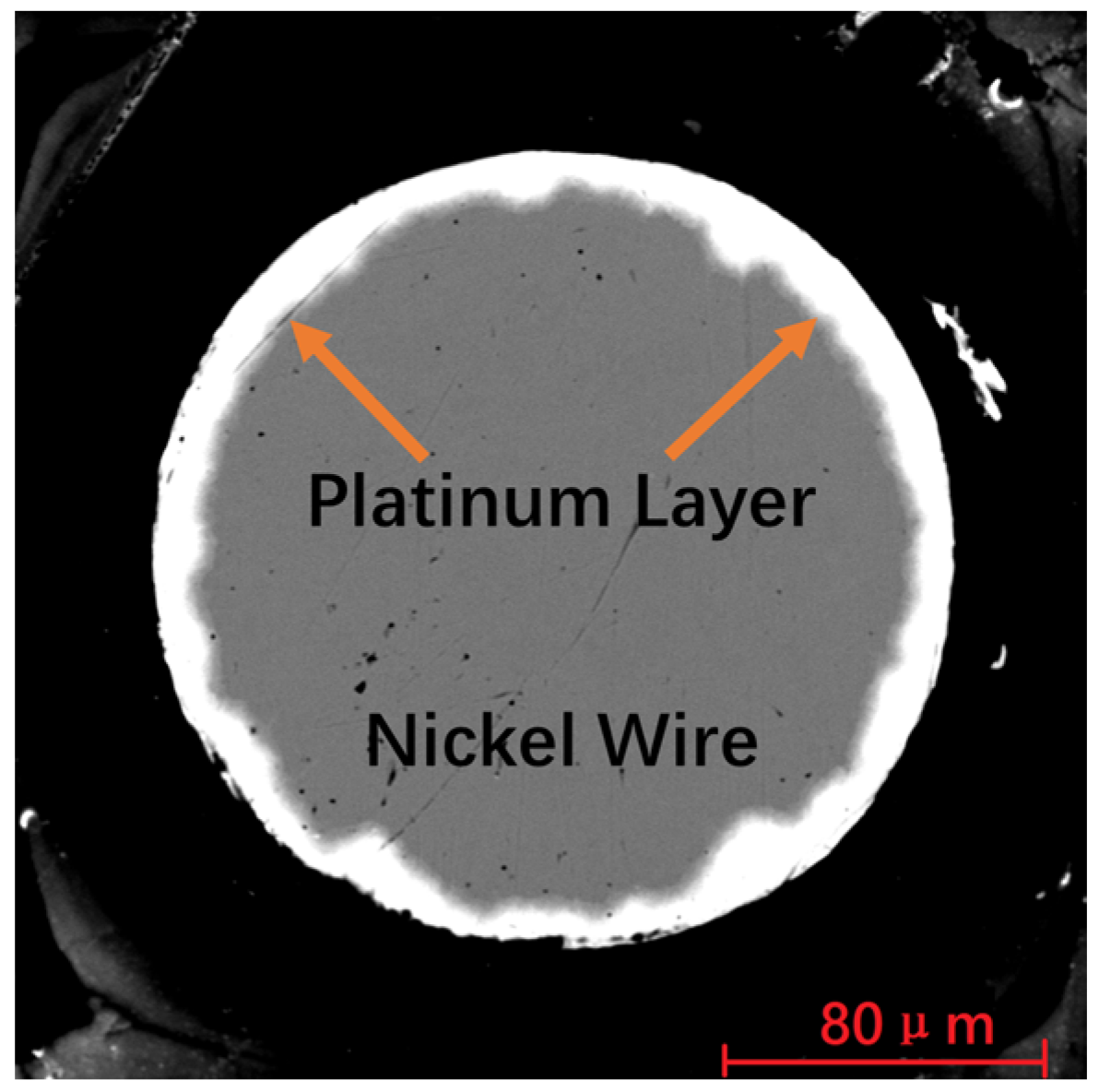
A typical application of platinum-clad nickel wire is for the field of high temperature [11], such as used for the lead wire of thin-film platinum resistance temperature sensors as shown in Figure 1; it can be used at temperatures from 0 to 500 °C. Each of the thin-film platinum resistance temperature sensors have two lead wires with a length of 8–10 mm and a diameter of 0.15–0.3 mm. The lead wire is made up of a platinum layer and nickel core wire, as shown in Figure 2, which is always contacted with the temperature measurement environment. The thickness of the platinum layer is only 5–8 μm and not only requires that the platinum layer is dense and has no leakage, but that it also has a strong binding force with the core material. Therefore, the key to improving the service life, stability, and reliability of composite materials is how to prepare platinum-clad nickel wires where the platinum layer is dense and has a strong binding force with the nickel.
At present, the research on platinum-clad nickel wire is still rare. Yang et al. [12] studied the preparation of platinum-clad nickel wire using the extrusion cladding method. It was found that a platinum-clad nickel wire with a metallurgical bonding interface can be prepared. The purity of the platinum layer reached more than 99.9%, which could meet the needs of users. Li et al. [13] used the welding–drawing method to prepare a platinum-clad nickel wire with a diameter of 0.2–0.3 mm and a platinum layer thinness of 0.02–0.03 mm. Results show that the platinum layer prevents the nickel wire from oxidizing during welding and that the platinum-clad nickel wire can be used as a lead wire instead of a pure platinum wire, with a cost of only 20–30% of the pure platinum wire.
The preparation methods of cladding composite materials include coating [14], cladding extrusion [15,16,17], continuous core-filling casting [18,19,20], plating [21], cladding drawing [22] and rotary swaging [23,24,25]. The cladding drawing is one of the main methods for preparing high-quality cladding composite materials in small batches, which has the advantages of a uniform and controllable coating, density and strong interfacial adhesion. The schematic diagram of its preparation process is shown in Figure 3. The processing steps are as follows: first step, platinum tube and nickel rod are prepared, respectively; second step, nickel rod is inserted into the platinum-tube and assembled into composite blank; third step, the composite blank is drawn together for the first step drawing; and then finally, the platinum-clad nickel wire meeting the size requirements is prepared by drawing and annealing multiple times. The first-step drawing is very critical when the clad drawing is adopted, because there is a gap between the platinum tube and the nickel rod in order to ensure that the nickel rod can be inserted into the platinum tube. During the first-step drawing, the platinum tube should not only fill the gap in the radial direction, but also extend in the axial direction, so that the platinum tube and nickel rod can be closely combined. Due to the great differences in the mechanical properties and plastic deformation ability of platinum and nickel, it is easy to produce defects, such as eccentricity, damage, and accumulation of the platinum layer. Therefore, it is meaningful to study the first-step drawing, which is related to the quality of the final product.
The finite element method has been widely used in the numerical simulation of the drawing process, which can not only analyze and optimize the metal flow, but also pre-validate the process, to reduce the cost and cycle of the research. Chai et al. [26] used FEM simulation to perform drawing force optimization research on the forming parameters of drawing wire rod with rotating die under coulomb friction, and the results show that the minimum drawing force is successfully obtained. Sas-Boca et al. [27] used 3D FEM to optimize the geometry dies, the result shows that drawing forces are strongly influenced by the half approach angle and length of bearing area. Bella et al. [28] used FEM to simulate the drawing progress of multi-rifled in order to find the proper feedstock dimensions and tool geometry. It was observed that the calculated results agreed with the actual numbers from the plant trials. Beland et al. [29] aims to optimize tool geometries using a finite element (FE) method, which will enable the performance of the tube drawing process in only one step. Based on the optimum design, a new tool was built and acceptable accordance was observed between experiments and numerical results. Liu et al. [30] researched the ultrasonic drawing process of fine titanium wire based on finite element analysis in terms of four factor. The results show that lower drawing velocity and larger ultrasonic amplitude contribute to a greater drawing force reduction. Through the analysis of the above literature, we know that most researchers have worked on the optimization of the drawing process, especially for a single material of wire. They suggested that the quality of wires are closely related to the drawing parameters, such as the amount of deformation, drawing speed, lubrication, the semi-angle of the dies and the lengthening of the calibrating strap of the dies. The most critical of these parameters is the semi-angle. Better drawing process can be obtained by optimizing the drawing parameters. However, few of them concentrate on optimizing the drawing parameters of the cladding bar. The first-step drawing of platinum-clad nickel bars is a special and complex deformation process. The quality of it is also closely related to the outer diameter of the original platinum tube (wall thickness of tube), the friction coefficient between platinum tube and drawing die, as well as the friction coefficient between the platinum tube and nickel bar. Therefore, it is necessary to optimize the combination of important drawing parameters, in order to obtain better drawing process parameters.
In this paper, a platinum-clad nickel bar was selected as experiment object. The modeling of the first-step drawing of the platinum-clad nickel bar was modeled using the DEFORM 3D V11 primitive geometric modeler, according to the actual production situation. Four important parameters of the first-step drawing, including semi-angle, outer diameter of the original platinum tube (wall thickness of tube), the friction coefficient between the platinum tube and drawing die and the friction coefficient between platinum tube and nickel bar, were optimized by combining DEFORM 3D V11 finite element analysis and the Taguchi method. In order to reach a better understanding of the plastic deformation of the platinum-clad nickel bar during the first-step drawing, deformation behavior, cladding behavior, the equivalent stress and damage values of platinum-clad nickel bar after drawing have been studied.
The objective of the study is to help the engineer to select the appropriate processing technology, to promote the product quality and to improve the yield of the finished products, which has important engineering practical value.

2. Materials and Model

2.1. Simplification and Assumption of Finite Element Model

The first-step drawing process of platinum-clad nickel bar is a complex deformation process. It is necessary to make certain the simplifications and assumptions in order to improve computational efficiency while ensuring that the calculation results are close to the actual performance of the material. The basic assumptions are as follows:
1.
Without considering the eccentricity and thickness deviation of platinum tube.
2.
Regardless of frictional heat and deformation work.
3.
The platinum and nickel are homogeneous and isotropic, and their intrinsic parameters such as density, elastic modulus and Poisson’s ratio do not change with temperature.
4.
The drawing die is simplified into four areas: the lubrication cone, work cone, calibrating strap and exit cone.
5.
The platinum-clad nickel bar is simplified to select 1/4 of the longitudinal section of the platinum tube, nickel rod and wire drawing die to establish a model for analysis.

2.2. Establishment of Geometric Model

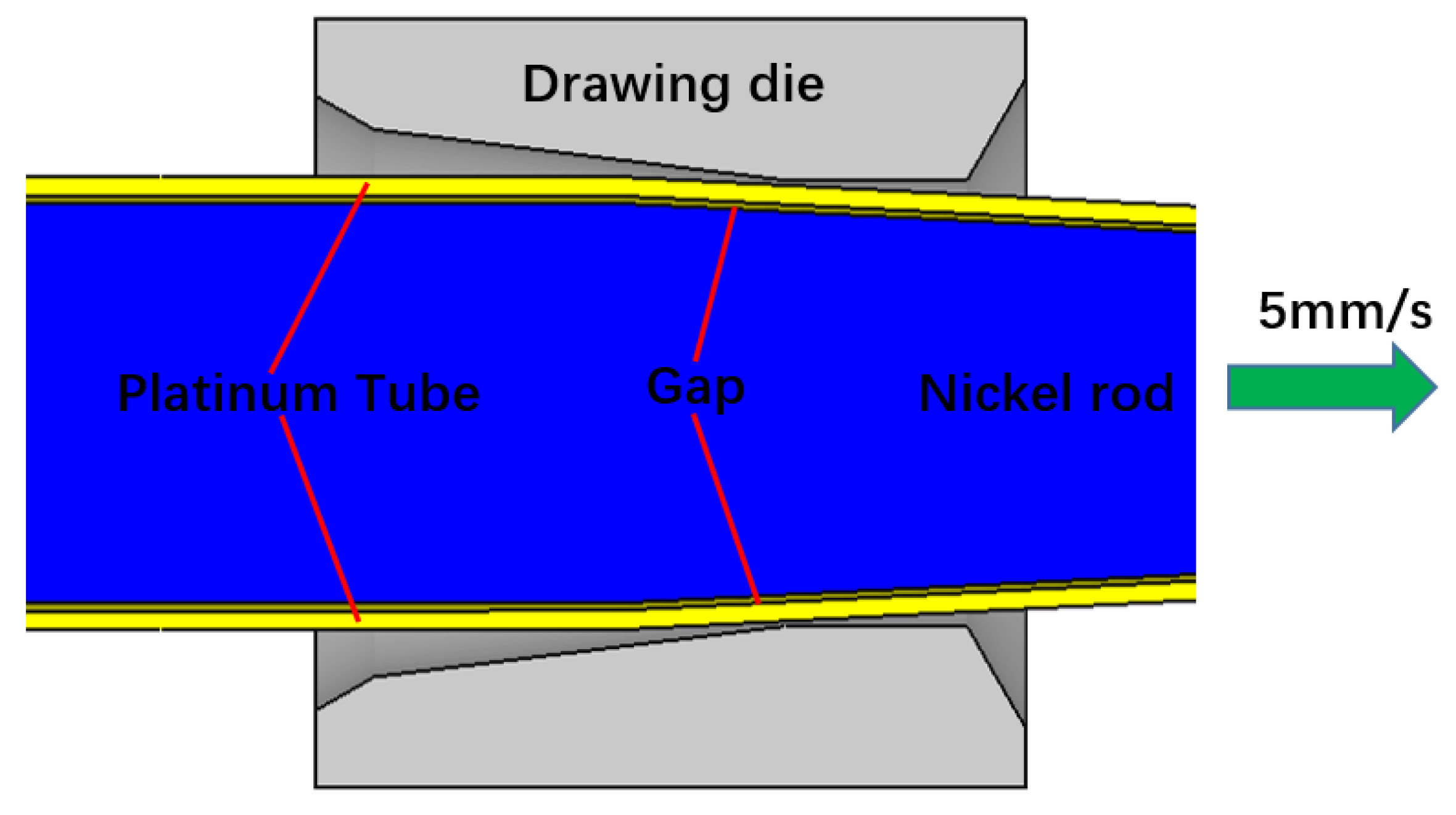
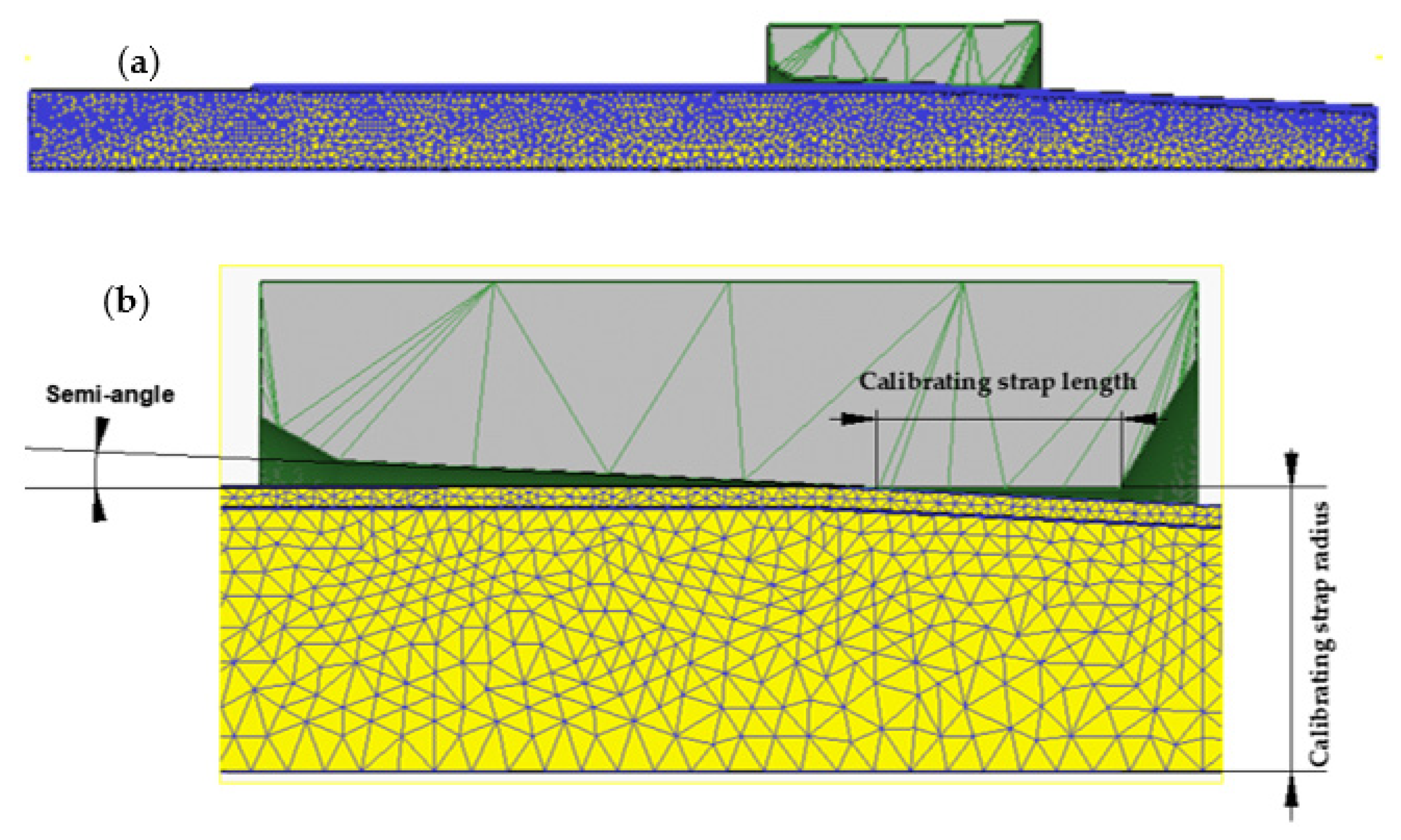
In this paper, the DEFORM 3D version 11.0 software (Scientific Forming Technologies Corporation, Columbus, OH, USA) is used for FEM simulation. The model is built by the primitive geometric modeler in the DEFORM 3D version 11.0 module. The properties of platinum and nickel are shown in Table 1. Figure 4 is a schematic diagram of the first-step drawing of platinum-clad nickel, including the platinum tube, nickel bar and drawing die. The length of the platinum tube is 50 mm with an effective deformation length of 30 mm, and the length of nickel bar is 60 mm with effective deformation length of 30 mm. The outer diameter of the nickel bar is 6.95 mm, the inner diameter of the platinum tube is 7 mm and the outer diameters are 7.55 mm, 7.60 mm, and 7.65 mm respectively. The gap between the nickel bar and the platinum tube is 0.025 mm. The material of the drawing die is AISI H13, the properties of which were obtained from the software database. The calibrating strap length of drawing die is 3 mm with a diameter of 7.5 mm. The die fillet is 1.5 mm. The semi-angle of the dies is 3°, 5°, 7°, respectively. The position of the drawing die is fixed, and the front-end of the nickel bar and platinum tube are drawn with the constant speed V, which is 5 mm/s. When the nickel bar and platinum tube pass through the drawing die, the outer diameter of the platinum tube will reduce to 7.5 mm. The FEM simulation conditions are as follows: (a) The nickel bars were discretized into 50,000 tetrahedral elements, and platinum tubes were discretized into 80,000 tetrahedral elements. The model after meshing is shown in Figure 5. (b): The friction types of between platinum tube and the drawing die and between platinum tube and nickel bar were assumed to be of a shear type and the constant friction ranged from 0.12 to 0.3. (c): The step increment is 0.04 mm/step. (d): The Lagrangian incremental simulation type with the Newton–Raphson method for the iteration process, global remeshing, relative interference depth type and sparse solver were chosen.

2.3. Taguchi Experimental Design

The Taguchi experimental design is an experimental method that uses orthogonal tables to select experimental conditions and arrange experiments, which can obtain the impact of variables on target values and discover the connectivity among the variables by conducting a small number of experiments. The optimization of effective stress was obtained using Taguchi method. Referring to the actual situation of drawing, there were four control factors considered for the first-step drawing process. They are the semi-angle of drawing dies (α, °), friction coefficient between the platinum tube and drawing die μ1, the friction coefficient between the platinum tube and nickel bar μ2 and the outer diameter of the original platinum (D, mm). Each control factor has three levels as shown in Table 2. Therefore, three level orthogonal arrays (L9 (34)) was employed to conduct a simulation, which includes nine experiments. The range analysis of the simulation results was performed using MINITAB 16 software.

3. Simulation Results and Analysis

3.1. Range Analysis of Simulation Results

In the first-step drawing of the platinum-clad nickel bar, it is desirable to have a lower effective stress on the platinum tube. Increasing the effective stress is imparted to the platinum tube, so the effective stress is one of the most important indices for the evaluation of the drawing process parameters. The L9 (34) orthogonal table is shown in Table 3. According to Table 3, nine experiments with different combinations of parameters were carried out. The FEM simulation was performed using Deform 3D, and the effective stress is obtained for each numerical simulation, which is an average value of the whole hundred steps. From Table 3, it can be seen that Numerical Simulations 1 has the smallest effective stress value at 141.6 MPa, whereas the Numerical Simulations 8 has the largest effective stress value at 282.4 MPa.
Table 4 is the response table of the range analysis. The larger the range RX of a factor is, the more significant the influence of the factor on the result is. It can be seen from Table 4 that the initial outer diameter of the platinum tube (D) has the greatest influence on the effective stress of the composite bar following by the semi-angle of the dies (α), the friction coefficient between the platinum tube and nickel bar (μ2) and the friction coefficient between the platinum tube and drawing die (μ1).
In Table 4, Level 1 is the average value of the corresponding analysis index at the (1, 2, 3) level of a factor. The level with the smallest effective stress was extracted and combined to obtain the optimal parameters’ combination as A1B2C3D1 (α = 3°, μ1 = 0.2, μ2 = 0.3, D = 7.55 mm).

3.2. Simulation and of Optimization Scheme

The first-step drawing of platinum-clad nickel bar was simulated again by using the optimal combination of parameters (α = 3°, μ1 = 0.2, μ2 = 0.3, D = 7.55 mm), and the effective stress was carried out as 140.9 MPa, which is smaller than the various simulation results of the orthogonal experiment. Therefore, the optimization of the effective stress is successfully achieved.

3.3. Analysis of Deformation Behavior

The effective strain of the nickel bar for optimization scheme is 0, and for Experiment 8 is only 0.000421 mm/mm. Although the parameters used in the two simulations are completely different, the effective strain value of the nickel bar is the same as 0. Therefore, during the first-step drawing process, the nickel rod does not deform, and only the platinum tube deforms.
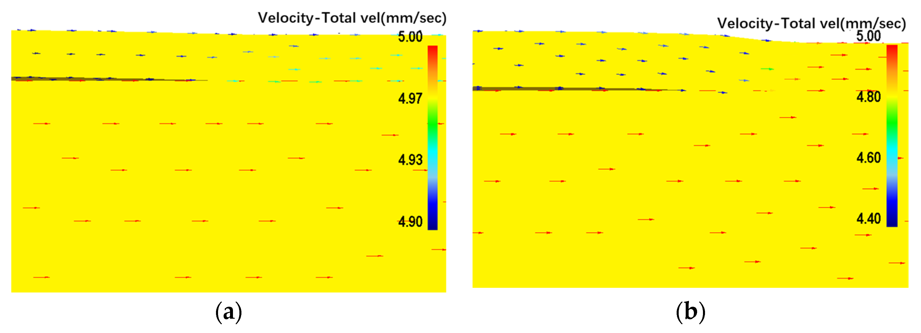
Figure 6 shows the velocity–total vel diagram for the optimization scheme and Numerical Simulations 8. The metal flow of platinum tubes is first compressed radially and then extended axially.

3.4. Analysis of Cladding Behavior

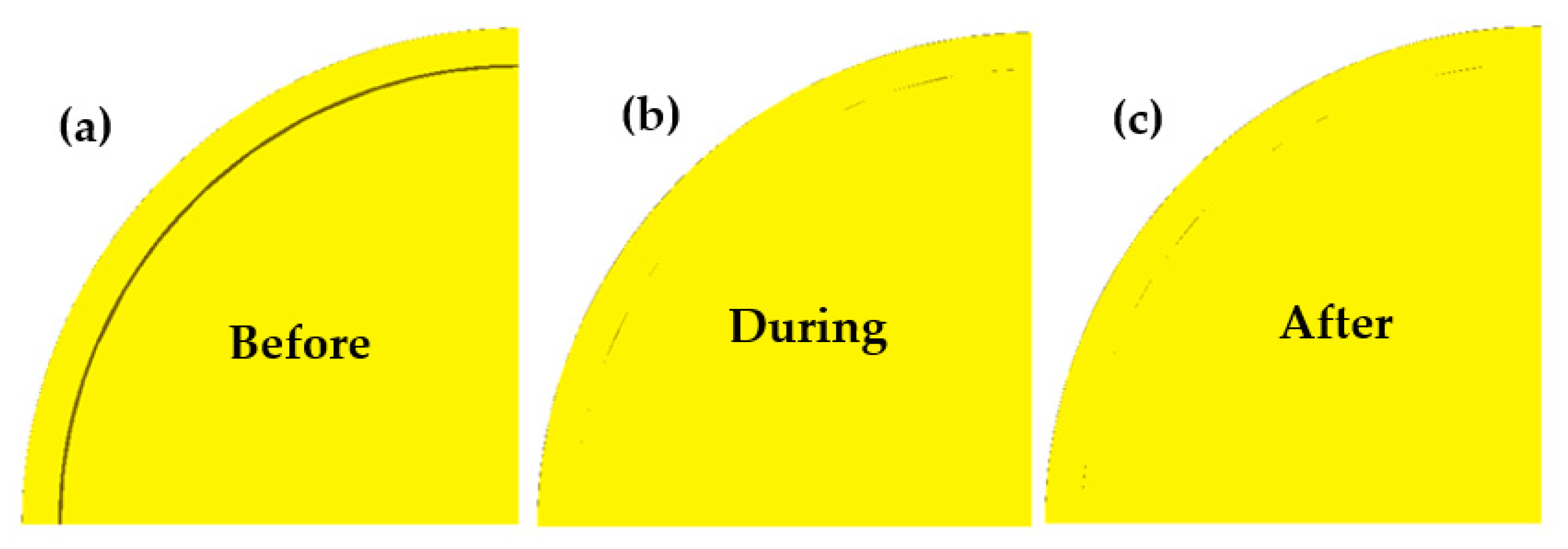
Figure 7 shows the cross-section of the platinum-clad nickel bar before, during and after the deformation simulated using the optimization scheme. There are intermittent gaps between the platinum tube and the nickel bar in the deformation area of the drawing die as shown in Figure 7b. This is because the thickness of the platinum tube is relatively thin at 0.25 mm. With a fixed gap and the final outer diameter, the theoretical elongation of the platinum tube is only 0.7%, which is mainly used to fill the gap. Moreover, the effective stress is relatively small as 140.9 MPa, so it is not enough to tightly fit the platinum tube and nickel bar under small effective stress. Figure 7c shows the cross-sectional after drawing. It can be seen from the figure that there are still gaps between the platinum tube and the nickel bar, but there is no significant increase or widening of the gap. This is because, in the case of a smaller outer diameter of the original platinum tube, the axial tensile stress is small. On the other hand, there is friction between the inner surface of the platinum tube and the outer surface of the nickel rod, so the tensile stress is not enough to separate the platinum tube from the nickel rod. Therefore, increasing the friction coefficient between the nickel rod and the platinum tube is beneficial.
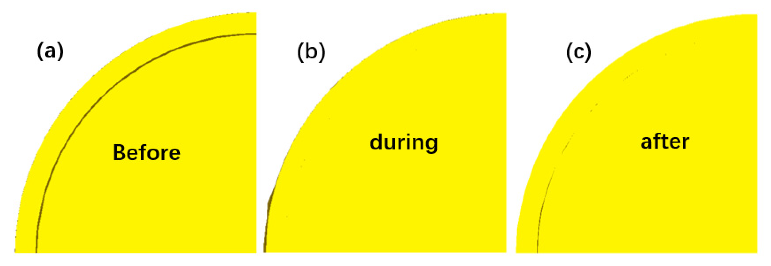
Figure 8 shows the cross-section of the platinum-clad nickel bar before, during and after deformation for Numerical Simulations 8, which used a large platinum tube wall thickness (0.325 mm) and a large semi-angle of the die (α = 7°) for simulation. There is no gap between the platinum tube and the nickel bar in the deformation area of the die, achieving a tight connection, as shown in Figure 8b. This is because the thickness of the platinum tube is relatively thick as 0.325 mm. With a fixed gap and the final outer diameter, the theoretical elongation of the platinum tube is 19.8%. Part of the platinum tube is used to fill the gap through the compression diameter, and the other part is used to extend in the axial direction. The effective stress is 282.4 MPa, which is twice that of the optimized scheme. Therefore, in the case of large effective stress, the platinum tube can be closely combined with the nickel rod. On the other hand, the larger effective stress is, the more likely it is that the platinum tube will be broken. Figure 8c shows the cross-section after deformation, and the gaps appear between the platinum tube and the nickel bar, which is continuous. This is because, in the case of a large outer diameter of the initial platinum tube, the axial tensile stress is greater than the friction force between the inner surface of the platinum tube and the outer surface of the nickel bar, causing the platinum tube to separate from the nickel bar again. The damage of secondary separation to the platinum tube is very great. Therefore, increasing the thickness of the platinum tube is harmful.

3.5. Analysis of Effective Stress

Figure 9 shows the diagram of effective stress of platinum-clad nickel bar for the optimization scheme and Numerical Simulations 8 during stable drawing stages. As shown in Figure 9, the nickel bar and platinum tube have the highest effective stress at the beginning of the bearing zone of drawing die. Due to the differences in simulation parameters, the effective stress distribution also varies. Figure 9a shows the effective stress distribution for optimization scheme using the thin thickness of the platinum tube at 0.25 mm and the small semi-angle of dies at 3°, the effective stress of the nickel bar is very small, meanwhile, the difference in effective stress values of the same section is not significant. The effective stress of the platinum tube is obviously larger than that of the nickel bar, but there is no obvious stress difference between the inner and outer surfaces, which is the same as the nickel rod. Figure 9b shows the effective stress distribution for Numerical Simulations 8 using the thick thickness of the platinum tube at 0.325 mm and the large semi-angle of dies at 7° for the simulation. The effective stress of the nickel bar gradually increases from the core to the outside of the diameter, but it is much smaller than that of the platinum tube at the same section. Therefore, the larger the thickness of the platinum tube, the greater deformation and the greater the effective stress. The dangerous section occurs at the beginning of the bearing zone of the drawing die, which may cause defects in the platinum tube, such as transverse cracks, damage or breaks. Therefore, it is necessary to control the deformation amount by controlling the thickness of the platinum tube to prevent excessive stress.

3.6. Analysis of Damage

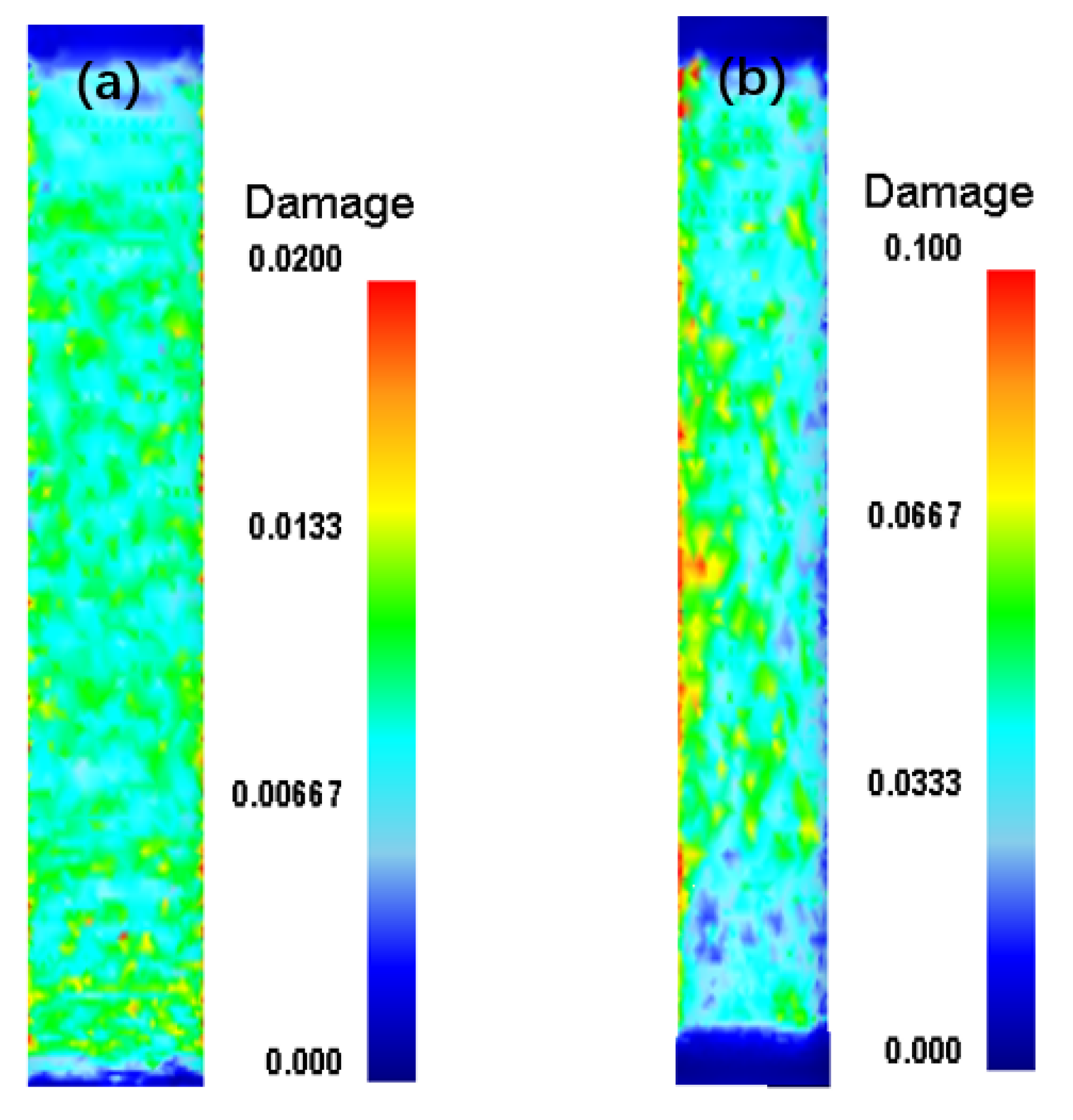
The damage value represents the probability of damage which is determined by the energy accumulated during the drawing process and is irreversible. Increases in the damage value indicate an increased tendency for defects such as fractures, build-up and skin breakage and other defects in the composite bar, especially in the platinum layer. Figure 10 shows the diagram of damage distribution of platinum tube for optimization scheme and Numerical Simulations 8 during the stable drawing stages. According to Figure 10, the damage value of Numerical Simulations 8 is 0.1, which is five times the optimization scheme. The greater the damage value, the greater the probability that the platinum tube is damaged. What is worse is that the damage distribution for Numerical Simulations 8 is more uneven than that for the optimization scheme, which is more likely to cause local damage to the platinum tube.

4. Confirmation Experiment

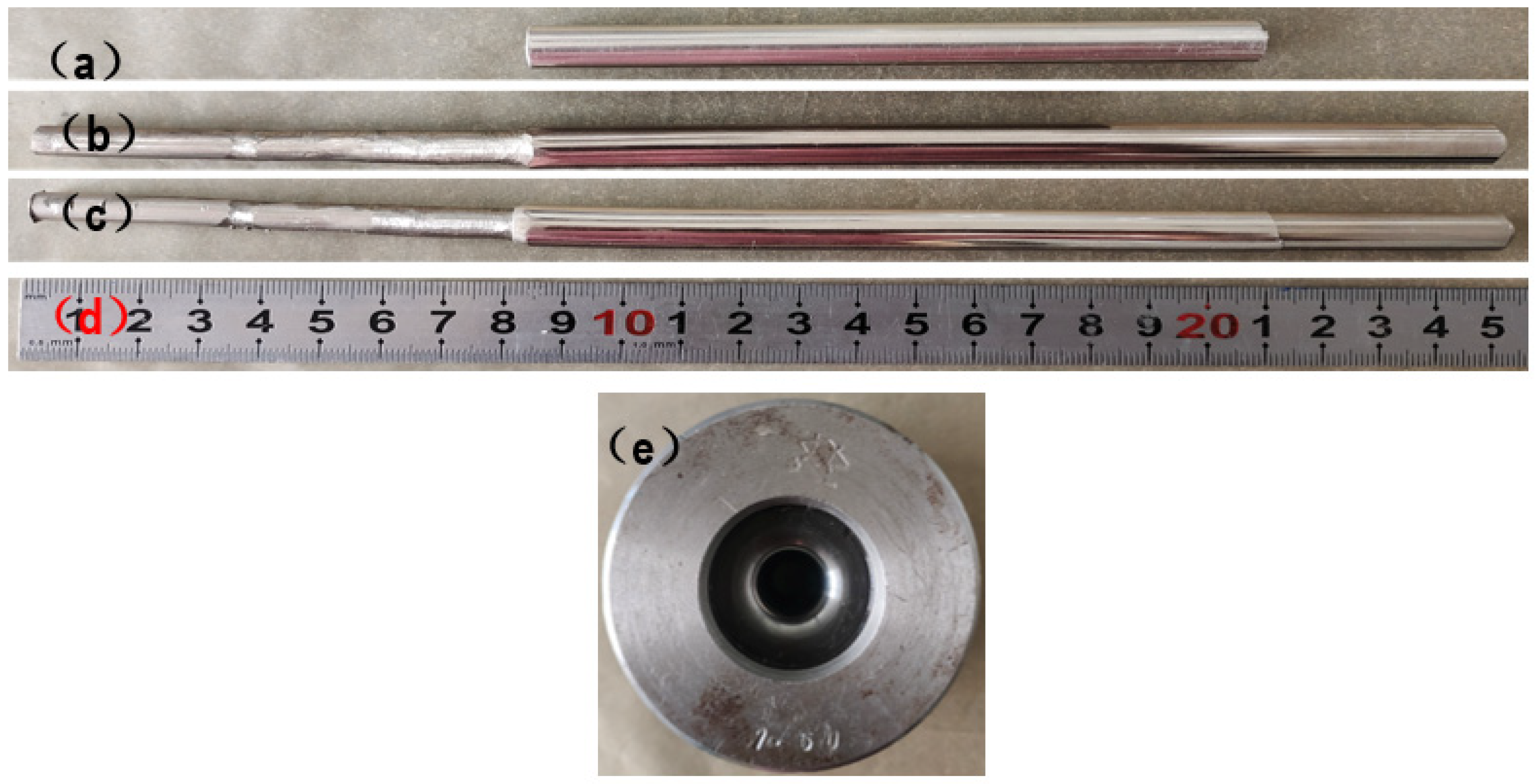
In the first-step drawing process, the platinum tube should be concentrically cladded on the nickel core, and the thickness of the platinum layer should be controlled. It is crucial that there is no breakage of the platinum tube. In order to verify the accuracy of the simulation results, experiments were carried out using the optimal combination of parameters (α = 3°, μ1 = 0.2, μ2 = 0.3, D = 7.55 mm), focusing on the surface quality and dimensions of the platinum layer. The platinum tubes and nickel rods were self-made by drawing. The length of platinum tube was 12.5 cm with an inner diameter of 7.00 mm and an outer diameter of 7.56 mm, as shown in Figure 11a. The length of the nickel bar was 25.1 cm with a diameter of 6.95 mm. In order to allow the nickel bar to pass through the drawing die and be held by the clamps of the drawing machine, one end of the nickel bar was rolled small, as shown in Figure 11b. Then, the nickel bar was inserted into a platinum tube followed by a vacuum heat treatment at 600 °C for 30 min. Finally, the platinum-clad nickel bar was drawn without the use of any lubricant. The calibrating strap diameter of drawing dies is 7.5 mm with a length of 3 mm and the semi-angle of 3°, as shown in Figure 11e. The photo of the platinum-clad nickel bar after the first-step drawing is shown in Figure 11c. According to Figure 11c, the platinum layer was very smooth and without any defects. The length of the nickel bar was still 25.1 mm, indicating that the nickel bar had not been deformed; only the platinum tube was deformed. The experimental results are in general agreement with the simulation results, indicating that our simulation results are plausible. Using the optimized parameters from the simulations, high-quality platinum-clad nickel composite bars can be prepared.

5. Conclusions

The purpose of this study is to research the optimization of the effective stress of platinum-clad nickel bars in the first-step drawing progress through combining DEFORM 3D finite element analysis and the Taguchi method to obtain the minimum effective stress. The deformation behavior, cladding behavior, effective stress and damage are obtained and compared. The results are listed as below:
1.
The optimal combination of parameters is A1B2C3D1 (α = 3°, µ1 = 0.2, µ2 = 0.3, D = 7.55 mm). The influence rank of parameters to the effective stress is listed as: outer diameter of the original platinum tube > semi-angle of drawing die > friction coefficient between platinum tube and nickel bar > friction coefficient between platinum tube and drawing die.
2.
During the first-step drawing process, the nickel bar does not deform. Only the platinum tube deforms. The experimental results are in general agreement with the simulation results.
3.
It is beneficial for a better coating to increase the friction coefficient between the platinum tube and nickel rod and reduce the original diameter of the platinum tube.
4.
The larger the thickness of platinum tube, the greater deformation as well as the greater the effective stress on. The dangerous section occurs at the beginning of the bearing zone of drawing die.
5.
Large and uniformly distributed effective stress can easily cause local damage to platinum tubes.

Author Contributions

Conceptualization, Y.C., X.C. and M.X.; methodology, Y.C. and X.C.; software, Y.C., J.H. and S.Z.; validation, Y.Y. and A.L.; formal analysis, Y.C. and A.L.; resources, Y.C., X.C. and M.X.; data curation, Y.C. and J.F.; writing—original draft preparation, Y.C. and J.F.; investigation, Y.Y. and A.L.; writing—review and editing, Y.C.; visualization, Y.C., J.H. and S.Z.; supervision, M.X.; project administration, Y.C. and J.H.; funding acquisition, Y.C. All authors have read and agreed to the published version of the manuscript.

Funding

This research was funded by the Innovation Team Project of Yunnan Province (202105AE160027) and the Plan Project of Yunnan Precious Metals Laboratory Co., Ltd. (YPML-2022050228).

Data Availability Statement

The data are available on request from the corresponding authors.

Conflicts of Interest

The authors declare no conflict of interest.

References

  1. Sharifian, A.F.; Jamal, H.S.; Jamshidi, A.H.; Roohollah, J. Fabrication of a novel high-strength and high-conductivity copper-clad aluminum composite wire. CIRP J. Manuf. Sci. Technol. 2023, 41, 144–159. [Google Scholar]
  2. Kocich, R.; Kunčická, L.; Král, P.; Strunz, P. Characterization of innovative rotary swaged Cu-Al clad composite wire conductors. Mater. Des. 2018, 160, 828–835. [Google Scholar] [CrossRef]
  3. Chen, D.L.; Li, X.; Pan, H.L.; Luan, H.Y.; Zhao, Z.J. Magneto-impedance effect of composite wires prepared by chemical plating under DC current. Nano-Micro Lett. 2014, 6, 227–232. [Google Scholar] [CrossRef]
  4. Tian, W.; Zhang, F.W.; Han, S.L.; Chen, X.H.; Gao, P.F.; Zheng, K.H. Analysis of microstructure and properties in cold rotary swaged copper-clad magnesium wires. Metals 2023, 13, 467. [Google Scholar] [CrossRef]
  5. Xiang, S.H.; Xu, J.Y.; Li, J.X.; Qiu, Y.C.; Yang, X.F.; Zhang, D.F. Study on the microstructure and mechanical properties of Cu-12%Nb composite wire during annealing. Rare Met. Mater. Eng. 2023, 52, 763–769. [Google Scholar]
  6. Bao, Y.; Huang, L.J.; Jiang, S.; Zhang, R.; An, Q.; Zhang, C.W.; Geng, L.; Ma, X.X. A novel Ti cored cire developed for wire-feed arc deposition of TiB/Ti composite coating. J. Mater. Sci. Technol. 2021, 83, 145–160. [Google Scholar] [CrossRef]
  7. Yang, Z.; Mi, X.J.; Feng, X.; Xie, H.F.; Peng, L.J.; Huang, G.J.; Li, Y.F.; Yin, X.Q. Interface evolution of Cu-Ni-Si/Al-Mg-Si clad composite wires after annealing. Rare Met. 2020, 39, 1419–1424. [Google Scholar] [CrossRef]
  8. Zhang, X.H.; Ning, Y.T. Platinum alloys and composites used for the glass manufacturing industry. Precious Met. 2013, 34, 88–94. [Google Scholar]
  9. Liu, H.; Yang, E.Q.; Wang, Y.H. Preparation and high temperature oxidation performance of platinum-aluminum coating on CMSX-4 single crystal superalloy. Liaoning Chem. Ind. 2022, 51, 325–328. [Google Scholar]
  10. Sun, C.F.; Liu, X.Q.; Shao, Z.C. A study on the platinum plating on molybdenum wire surface. Electroplat. Pollut. Control 2013, 33, 26–28. [Google Scholar]
  11. Zeng, Y.J.; Chen, G.C.; Wu, C.; Pan, X.C.; Lin, F.; Xu, L.D.; Zhao, F.X.; He, Y.P.; He, G.H.; Chen, Q.N.; et al. Thin-film platinum resistance temperature detector with a SiCN/Yttria-stabilized zirconia protective layer by direct ink writing for high-temperature applications. ACS Appl. Mater. Interfaces 2022, 15, 2172–2182. [Google Scholar] [CrossRef]
  12. Yang, Y.K.; Yan, X.F.; Huang, G.L.; Bo, X.P. Manufacturing of platinum-nickel 30/70 compound wires. Electr. Mater. 2006, 1, 6–9+13. [Google Scholar]
  13. Li, G.G.; Kuan, A.L.; Hu, Z.; Liu, Z.P.; Pan, C.G. Resistance lead. Chinese Patent CN207731673U, 14 August 2018. [Google Scholar]
  14. Wang, X.; Guan, R.G.; Zhang, Y.; Su, N.; Ji, L.Z.; Li, Y.D.; Chen, T.J. Microstructure evolution and properties of Al/Al–Mg–Si alloy clad wire during heat treatment. Appl. Phys. A 2016, 122, 615. [Google Scholar] [CrossRef]
  15. Sun, D.; Wang, Z.; Jiang, S.; Zhang, Y. Interface compatibility During different-temperature Cu/NbTi cladding extrusion: Simulation and experiment. Rare Met. Mater. Eng. 2023, 52, 441–447. [Google Scholar]
  16. Lee, J.K.; Lee, S.P.; Lee, J.S.; Lee, S.; Jo, I.; Bae, D.S. Change of microstructure and hardness of duo-casted Al3003/Al4004 clad material during extrusion process. Metals 2020, 10, 1648. [Google Scholar] [CrossRef]
  17. Kuhnke, S.; Gensch, F.; Nitschke, R.; Sanabria, V.; Mueller, S. Influence of die surface topography and lubrication on the product quality during indirect extrusion of copper-clad aluminum rods. Metals 2020, 10, 888. [Google Scholar] [CrossRef]
  18. Xue, Z.Y.; Liang, H.; Yu, W.H. Orthogonal tests of copper-clad aluminum bimetal continuous casting by nitrogen pressure core-filling. China Foundry 2013, 10, 385–390. [Google Scholar]
  19. Tang, X.K.; Liu, X.H.; Xie, G.L. Interfacial microstructure and properties copper cladding aluminum alloy composites. Chin. J. Rare Met. 2022, 46, 862–872. [Google Scholar]
  20. Shi, B.B.; Liu, X.H.; Xie, J.X.; Xie, M. Preparation process for silver clad aluminum bars by vertical continuous casting composite forming. Chin. J. Eng. 2019, 41, 633–645. [Google Scholar]
  21. Onodera, M.; Shinma, Y.; Meguro, K.; Tanka, J.; Kasai, J. Wire bonding using Pd plated Cu wire. J. Jpn. Inst. Electron. Packag. 2008, 11, 444–450. [Google Scholar] [CrossRef] [Green Version]
  22. Moisy, F.; Gueydan, A.; Sauvage, X.; Guillet, A.; Keller, C.; Guilmeau, E.; Hug, E. Influence of intermetallic compounds on the electrical resistivity of architectured copper clad aluminum composites elaborated by a restacking drawing method. Mater. Des. 2018, 155, 366–374. [Google Scholar] [CrossRef]
  23. Lou, M.X.; Liu, X.H.; Jiang, Y.B.; Xie, J.X.; Xie, M. Rotary swaging-drawing formation, microstructure, and properties of copper-clad aluminum composite micro-wires. Chin. J. Eng. 2018, 40, 1358–1372. [Google Scholar]
  24. Wan, J.F.; Zhao, F.; Liu, X.H. Microstructure and properties of copper-clad beryllium copper wire fabricated by rotary swaging. Chin. J. Nonferrous Met. 2023, 33, 729–740. [Google Scholar]
  25. Liu, X.H.; Zou, W.J.; Fu, H.D.; Liu, X.F.; Xie, J.X. Cu/Ti bimetal composite pipe fabricated by heating rotary swaging forming and its Interface, microstructure and properties. Chin. J. Rare Met. 2017, 41, 364–370. [Google Scholar]
  26. Chai, U.C.; Tzou, Y.Y.; Tiong, I.K. Drawing force optimization research on forming parameters of drawing wire rod with rotating die under coulomb friction. Mater. Sci. Forum 2018, 920, 3–9. [Google Scholar] [CrossRef]
  27. Sas-Boca, I.M.; Tintelecan, M.; Pop, M.; Ilutiu-Varvara, D.A.; Mihu, A.D. The wire drawing process simulation and the optimization of geometry dies. Procedia Eng. 2017, 181, 187–192. [Google Scholar] [CrossRef]
  28. Bella, P.; P Buček, P.; Ridzoň, M.; Mojžiš, M.; Parilák, L. Numerical simulation of multi-rifled tube drawing-finding proper feedstock dimensions and tool geometry. In IOP Conference Series: Materials Science and Engineering; IOP Publishing: Bristol, UK, 2017; Volume 179. [Google Scholar]
  29. Béland, J.F.; Fafard, M.; Rahem, A.; D’Amours, G.; Côté, T. Optimization on the cold drawing process of 6063 Aluminium tubes. Appl. Math. Model. 2011, 35, 5302–5313. [Google Scholar] [CrossRef]
  30. Liu, S.; Shan, X.B.; Cao, H.Q.; Xie, T. Finite element analysis on ultrasonic drawing process of fine titanium wire. Metals 2020, 10, 575. [Google Scholar] [CrossRef]
  31. Ning, Y.T.; Yang, Z.F.; Wen, F. Platinum; Metallurgical Industry Press: Beijing, China, 2010. [Google Scholar]
  32. Zhu, G.H.; Xiao, H.F.; Sui, F.L. Flow stress model of pure Al/Ni for cold deformation and its application. J. Anhui Univ. Technol. (Nat. Sci.) 2011, 28, 205–209. [Google Scholar]
Figure 1. The schematic diagram of thin-film platinum resistance temperature sensors.
Metals 13 01201 g001
Figure 2. The cross-sectional structure of lead wire.
Metals 13 01201 g002
Figure 3. The diagram of the process of preparing platinum-clad nickel composite wires by cladding drawing method.
Metals 13 01201 g003
Figure 4. Schematic diagram of the first-step drawing of the platinum-clad nickel bar.
Metals 13 01201 g004
Figure 5. The model after meshing: (a) overall view, (b) partial enlarged view.
Metals 13 01201 g005
Figure 6. The velocity–total vel diagram: (a) for optimization scheme, (b) Numerical Simulations 8.
Metals 13 01201 g006
Figure 7. The cross-sectional of platinum-clad nickel bar for optimization scheme: (a) before drawing, (b) during drawing, (c) after drawing.
Metals 13 01201 g007
Figure 8. The cross-section of platinum-clad nickel bar for Numerical Simulations 8: (a) before drawing, (b) during drawing, (c) after drawing.
Metals 13 01201 g008
Figure 9. The diagram of effective stress of platinum-clad nickel bar: (a) optimization scheme, (b) Numerical Simulations 8.
Metals 13 01201 g009
Figure 10. The damage distribution of platinum tube: (a) optimization scheme, (b) Numerical Simulations 8.
Metals 13 01201 g010
Figure 11. The photos of experiment: (a) platinum tube, (b) nickel bar, (c) after drawing, (d) ruler, (e) drawing die.
Metals 13 01201 g011
Table 1. Material Conditions.
ParametersPlatinum TubeNickel BarDrawing Die
MaterialPlatinumNickelAISI H13
Object typePlasticPlasticRigid
Young’s modulus, E [GPa]169207-
Poisson’s ratio, υ 0.3340.31-
Power law [MPa] σ = 366.3 ε 0.482 + 60   [31] σ = 530 ε 0.17372 [32]-
Number of elements80,00050,000-
Table 2. Factors and levels of Taguchi’s method.
Factor LevelABCDResponse Variable
MPa
α (°)μ1μ2D (mm)
Level 130.120.127.55effective stress
Level 250.200.207.60
Level 370.300.307.65
Table 3. The L9 (34) orthogonal table and simulation results.
Simulations NoA (α)B (μ1)C (μ2)D (D)Effective Stress (MPa)
130.120.127.55141.6
230.20.27.60207.4
330.30.37.65253.8
450.120.27.65274.4
550.20.37.55146.8
650.30.127.60226.5
770.120.37.60227.3
870.20.127.65282.4
970.30.27.55159.9
Table 4. Response table of range analysis.
Factor LevelA (α)B (μ1)C (μ2)D (D)
Level 1200.9214.4216.8149.4
Level 2215.9212.2213.9220.4
Level 3223.2213.4209.3270.2
Range22.32.37.6120.8
Rank2431
Disclaimer/Publisher’s Note: The statements, opinions and data contained in all publications are solely those of the individual author(s) and contributor(s) and not of MDPI and/or the editor(s). MDPI and/or the editor(s) disclaim responsibility for any injury to people or property resulting from any ideas, methods, instructions or products referred to in the content.