Abstract
Electron beam melting (EBM) is an additive manufacturing technique with the ability to produce porous implants with desired properties for orthopedic applications. This paper systematically investigated the mechanical properties and in vivo performance of two commonly used stochastic porous structures (the Voronoi structure and the randomized structure) fabricated by the EBM process. The pore geometries of two porous structures were characterized through micro-computed tomography (μCT). In addition, clinically relevant mechanical performances were evaluated for both structures, including tensile testing, shear testing and abrasion resistance testing. In vivo assessment of the two porous structures was further conducted in a dog model for three different follow-up periods. It was found that the Voronoi structures showed a higher mechanical strength compared to the randomized structures, even though both structures exhibited similar pore geometries. Further analysis revealed that the non-uniform stress distribution caused by the sample size and boundary effects led to a decrease in strength in the randomized structures. The in vivo assessments revealed the Voronoi structure exhibited a higher bone ingrowth ratio compared to the randomized structure due to its radially oriented pore geometry and homogenous pore size distribution. This study suggested that the EBM Ti-6Al-4V Voronoi porous structure has favorable mechanical performance and good osseointegration properties for orthopedic implants.
1. Introduction
Titanium alloys are considered ideal implant materials for their good biocompatibility and mechanical properties [1], which are widely used in orthopedic implants such as acetabular cups, femoral stems, and spinal fusion cages. Titanium porous structures play an important role in the orthopedic field, due to their wide applications in prosthetic implantation, such as artificial joint replacement and repair of bone defects caused by infection, trauma, or tumor resection [2]. One of the most concerning issues with porous orthopedic implants is the long-term loosening of implanted prostheses, for the following reasons. Traditionally, prosthetic surface coating technologies [3,4,5], such as metal powder spraying, microbeading or wire sintering, are used to create a porous coating on the surface of the implants for a relatively stable bonding effect between the coating and the bone. Besides, surface modifications of additively manufactured titanium were also used for bone contact applications and bone integration [6,7,8]. However, the weak bonding strength between the coating and the substrate could potentially increase the risk of coating shedding and wear between the articular surfaces. Such accumulated wear particles could result in osteolysis at the interface, which further leads to prosthetic loosening [9]. Besides, the porous coatings fabricated by the currently used surface coating technologies usually exhibit a relatively low porosity and uncontrollable pore shape, which have an undesirable effect on the growth, remodeling, and healing of the bone. In addition, the significant mismatch in stiffness between the solid metal implants and the bones could lead to stress shielding, bone resorption, and long-term implant failure [10].
Additive manufacturing (AM) technology, which can fabricate complex components with unique functions and distinctive structures [11], provides technical support for the fabrication of porous implants [12,13,14]. Owing to the layer-by-layer building approach and the direct link with a computer-aided design (CAD) model [15], AM techniques can fabricate porous implants with a controlled pore geometry. Porous structures made by AM technology can achieve controlled pore size, pore shape, and porosity, resulting in repeatable pore characteristics and mechanical properties [16]. Such porous structures show excellent osseointegration performance due to their interconnected pore geometry. Besides, the porous structures exhibit a similar modulus to natural bone at 10–30 GPa, which matches the physiological stress distribution and decreases the stress shielding effect.
Porous structures are often defined as networks of interconnected struts or walls. Depending on their topological regularity, porous structures can be categorized into stochastic and regular structures [17]. Regular structures typically exhibit 2D or 3D topological periodicity (i.e., repeating and ordered unit cells) [18,19], which have a uniform pore size, consistent unit morphology, and controllable porosity. However, such uniform and consistent pore geometries do not match the natural bone geometry. Therefore, stochastic porous structures are designed to mimic the human trabecular bone. Such stochastic porous structures present random variations in the pore’s geometry and dimension, which could be additional potential factors that improve the biocompatibility of porous implants in orthopedic applications [20,21].
The stochastic porous structures can be modeled in different ways, such as the mathematical modeling method and the randomization method [22,23]. The randomization method has been widely used in some commercial orthopedic products, such as acetabular cups and fusion cages [24,25,26]. The randomization works by upscaling and downscaling a given unit cell. Each unit cell is scaled up and down by a given percentage. This variation around the reference unit cell is a normal distribution, so the pore size will be distributed/scaled up and down accordingly, which results in a randomized porous structure. On the other hand, porous structure modeling based on Voronoi tessellation as a new modeling approach has increasingly gained interest in recent years [27,28,29]. This modeling approach presents excellent performance in constructing irregular porous structures in nature [30,31,32]. For the modeling of Voronoi lattice structures, a probability sphere method based on Voronoi tessellation was first used to generate random seeds to construct irregular porous structures with full connectivity. Additionally, the random seeds were then connected by beams according to the Voronoi algorithm. Such connected beams finally generate the Voronoi porous structures. For both randomized porous structures and Voronoi porous structures, many studies have been carried out for the evaluation of their mechanical and biological properties [33,34]. However, most of the mechanical property evaluations were implemented through tensile and compression testing, which could only cover a small portion of the mechanical properties in orthopedic applications. For example, apart from the tensile strength, both the shear strength and wear resistance also play quite an important role for orthopedic implants, due to their complex loading conditions in the human body. In orthopedic applications, porous structures are usually designed and fabricated on the surface of the solid substrate for bone ingrowth to balance the osteogenic capability and load-bearing capability. The porous structure may suffer tensile or shear loading after being implanted into the human body, which may lead to trabecular failure and fracture. Besides, the porous implant may abrase the human bone during daily movement. Excess particle shedding during abrasion could cause osteolysis around the porous implant. Therefore, investigations of appropriate mechanical properties related to the clinical use of porous structures are of great significance for orthopedic applications. In this study, mechanical properties, including tensile, shear, and wear resistance, were studied for two commonly used stochastic porous structures (the randomized structure and the Voronoi structure). In addition, their in vivo performance was investigated to provide a comprehensive and intuitive evaluation for their application in orthopedics.
In this work, to systematically investigate the mechanical and in vivo performances of the stochastic porous structures, the porous samples modeled by randomization and Voronoi tessellation approaches were designed and fabricated by the electron beam melting process with Ti-6Al-4V powders. In detail, the manufacturability and morphology of the two different porous structures were evaluated. Then, the mechanical properties of the two porous structures were investigated, and their different mechanical responses were further discussed. Significantly, the in vivo assessment of porous structures with varying pore geometries was also studied through animal experiments.
2. Materials and Methods
2.1. Materials
The commercial Ti-6Al-4V powder supplied by Xi’an Sailong Metal Materials Co., Ltd. (Xi’an, China) was used in the experiment. The chemical composition of the powders is shown in Table 1. As shown in the scanning electron microscopy (SEM) image in Figure 1 (SIGMA, Zeiss, Oberkochen, Germany), the powder had high sphericity and few satellite spheres, with a particle size range of 54–106 μm.

Table 1.
Chemical composition of the Ti-6Al-4V powders (%).
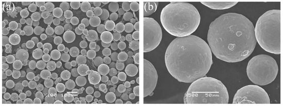
Figure 1.
SEM micrograph of Ti-6Al-4V powders: (a) 100× magnification; (b) 500× magnification.
2.2. Design and Fabrication of Porous Scaffolds
In this study, two commonly used stochastic porous structures were investigated, including the Voronoi lattice structure and the randomized dodecahedron structure. For the Voronoi lattice structure, a probability sphere method based on Voronoi tessellation was first used to generate random seeds to construct irregular porous structures with full connectivity. Additionally, the random seeds were connected by beams according to the Voronoi algorithm. Finally, a thickness was set for each beam to generate the Voronoi lattice structures, as shown in Figure 2a. For the randomized dodecahedron structure, a dodecahedron unit cell was first selected and then repeated in 3D space, which formed a uniform lattice structure. Then, a minimal and maximal scale was applied to the uniform lattice structure in the xyz direction to generate the randomization effect, as shown in Figure 2b.
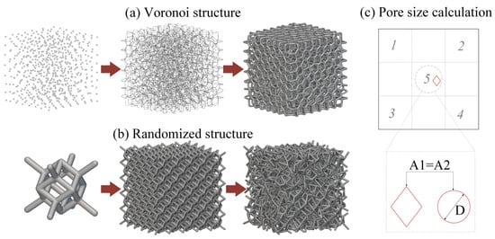
Figure 2.
Schematic image of stochastic porous structure modeling of (a) the Voronoi structure and (b) the randomized structure; and the calculation method of the pore size for the porous structures (c).
To fabricate the samples that were used in the study, the electron beam melting process was selected, which is currently a comparatively advantageous powder bed fusion additive manufacturing process for the fabrication of porous structures. The samples were manufactured by a Y150 Electron Beam Melting system (Xi’an Sailong Metal Materials Co., Ltd., Xi’an, China) using Ti6Al4V powders. As the study mainly focused on the design aspects of the porous, no special attempt was made to characterize the powder feedstock characteristics or optimize the system or process parameters. The default canned process parameters for the cellular structures (Ti6Al4V-Network) were used for the fabrication. The layer thickness was set to 50 µm. During the process, the powder bed was first preheated by a slightly defocused beam, with the beam current gradually ramping from 0 up to 35 mA over a span of 17 s, per the default setting. Preheating lightly sinters the powder bed in order to produce a more stable layer condition upon subsequent melting. Preheating also introduces an elevated powder bed temperature, which reduces thermally induced stresses in the fabricated parts. Following preheating, the struts were melted using a beam current setting of 4.5 mA. The exact beam current is geometry specific and is determined by the control algorithm’s proprietary functions.
2.3. Measurement and Characterization
A micro-computed tomography (μCT) scanner (d5, Diondo company, Hattingen, Germany) with a 5 μm resolution was used to scan the porous samples (Voronoi lattice and randomized structure, 10 mm × 10 mm × 5 mm) at 110 kV and 110 mA. Two-dimensional projection images were collected. The 3D models of the fabricated samples were reconstructed through these slice image data using commercially available software (VGStudio MAX 3.3, Volume Graphics GmbH, Heidelberg, Germany). Based on the above 2D and 3D μCT data, some important features of porous structures were calculated, including porosity, strut thickness, and pore size, which would directly affect bone ingrowth. Porosity was defined as the volume of the pores divided by the volume of the whole sample. The strut thickness was defined as the diameter of the struts. Usually, the pore geometries of the porous structures are irregular and not circular. Therefore, the pore size was defined as the equivalent diameter of the pores, which is shown in Figure 2c. Due to the irregular shape of the pores, the area for the irregular shape (A1 in Figure 2c) was first calculated using image processing software. Additionally, this area is defined to be equivalent to the area of a circle (A2 in Figure 2c). Finally, the equivalent diameter of the pore (D in Figure 2c) can be calculated using the equivalent circle area. The porosity, strut thickness, and pore size were investigated and calculated from three planes, including the xoz, yoz, and xoy planes. For the strut thickness and pore size, 5 areas were chosen for the calculation in each plane.
2.4. Mechanical Testing
Mechanical properties related to the clinical use of the porous structures were investigated in this study, including tensile testing, shear testing, and abrasion resistance testing. For all three tests, two different porous geometries (the Voronoi structure and the randomized structure) were investigated.
In order to assess the strength of the porous structures, tensile testing and shear testing were conducted according to ASTM F1146-05 and ASTM F1044-05, as shown in Figure 3a,b, respectively. Both tests were conducted using an electric universal testing machine (UTM 5105, SUNS Company, Shenzhen, China). For tensile testing, the tensile load was applied to each test specimen at a constant crosshead speed of 0.25 cm/min. For shear testing, the shear load was applied to each test specimen at a constant crosshead speed of 0.25 cm/min. The maximum load applied was recorded for the calculation of the tensile strength and shear strength of the porous structures. The tensile and shear strengths were defined by the maximum tensile and shear loads divided by the cross-section areas of each sample. For each test, three replications were conducted.
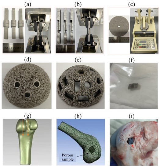
Figure 3.
Fabricated porous samples for mechanical properties and the corresponding testing devices: (a) tensile testing; (b) shear testing; (c) abrasion resistance testing. The porous implant preparation (d–f) and the implantation of the porous implant (g–i): (d) acetabular cup with the designed porous geometry; (e) acetabular cup after cutting; (f) the sterilized porous implant; (g) the femur model of beagle dog; (h) schematic image of the implantation; (i) the porous implant in the dog femur.
Abrasion resistance testing was conducted according to ASTM F1978-12, as shown in Figure 3c. The test used a TABER Rotary Platform Abrasion Tester (Model 5135, TABER Industries Company, North Tonawanda, NY, USA) with H-22 Calibrade (trademarked) wheels and a 250 g mass of the abrading head without added weights. The specimen was abraded using rotary rubbing action under controlled conditions of pressure and abrasive action. The test specimen, mounted on a turntable platform, turned on a vertical axis against the sliding rotation of two abrading wheels. One abrading wheel rubbed the specimen outward toward the periphery and the other inward toward the center. The resulting abrasion marks formed a pattern of crossed arcs over an area of approximately 30 cm2. Specimens were abraded repeatedly and cleaned ultrasonically for a set number of rotational cycles. The specimens were weighed after each cleaning, and the mass loss was the measure of abrasive wear to the specimen. Three replications were tested for each design.
2.5. In Vivo Assessment
In vivo assessment of porous structures fabricated by electron beam melting (EBM) was conducted in a dog model. Additionally, for the in vivo assessment, two porous geometries were investigated. To better assess the in vivo behavior of the real porous implants, the specimens were cut from two commercial acetabular cups with two selected porous geometries (Figure 2a,b) and then sterilized, as shown in Figure 3d–f. The beagle dog was selected as the in vivo model in this study due to the similarity of the biomechanical characteristics between the beagle dogs and humans. Before the implantation, the animals were raised in the breeding area after the quarantine period. The electric drill and osteotome were used to manually make bone defects of appropriate size (make a bone defect according to the actual size of the sample, the sample is a long strip of 10 mm × 5 mm × 5 mm), as shown in Figure 3g,h. The porous implants were put into the defect (the depth is 10 mm), as shown in Figure 3i. After the implantation, the wound was washed with antibiotic saline and then sutured layer by layer. Nine Beagle dogs were bred in this study for three different follow-up periods (1 month, 3 months, and 6 months) for histopathological observation, including the ingrowth of the new bone. For each follow-up period, 3 animals were observed. For each animal, the Voronoi specimen and the randomized specimen were randomly implanted into two femurs to eliminate the individual differences among animals.
3. Results
3.1. Morphological Characterization
The morphology and local characteristics of porous samples are characterized using μCT for Voronoi structures and randomized structures, as shown in Figure 4. Figure 4a,d exhibits the μCT data for porosity calculations. Figure 4b,e exhibits the μCT data for pore size calculations. Figure 4c,f exhibits the μCT data for strut thickness calculations. The light-colored area in the pictures indicates the solid strut, while the rest of the area is the pores without any materials. From Figure 4, it can be observed that the fabricated struts of both porous samples were dense, with only a few tiny pores. In addition, some partially melted powders were found attached to the surfaces of the struts for both samples. The struts of the porous structures were oriented spatially in different directions. These struts were usually fabricated without any support structures, resulting in some fully or partially melted powder attached to the struts, which then adhered to the bottom, leading to an overhanging phenomenon of accumulated particles on the surface of the struts, which is the main reason for the partial melted powder on the surface.
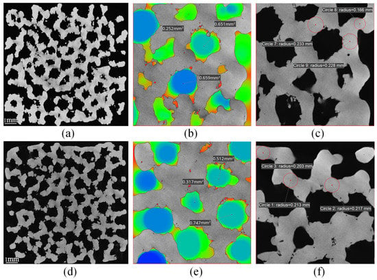
Figure 4.
μCT feathers of porous structures: porosity calculation (a), pore size calculation (b), and strut thickness (c) of the Voronoi structure; porosity calculation (d), pore size calculation (e), and strut thickness (f) of the randomized structure.
As the main morphological parameters of a porous structure, the strut thickness, porosity and pore size of two different samples were measured, calculated from the μCT data (shown in Figure 4), and compared to their respective design values, which are shown in Figure 5. Generally, the strut thicknesses of both as-built porous structures were higher than the, respectively designed CAD values. This increased the total volume of the solid struts, resulting in decreased pore size and porosity compared to the designed values, respectively.
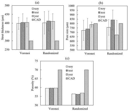
Figure 5.
Comparisons of the main feathers of porous structures: (a) strut thickness of two structures; (b) pore size of two structures; (c) porosity of two structures.
For the strut thickness, the Voronoi structure had an overall average thickness of 402 μm, while the randomized structure showed a thickness of 408 μm. In addition, the strut thickness in different planes exhibited a relatively consistent distribution for both designs, as shown in Figure 5a. Besides, both structures did not show an obvious difference between each other (p value = 1.0) when the designed value was 300 μm. The difference between the actual value and the designed value was caused by the electron beam resolution. The diameter of the electron beam was 300 μm. When the electron beam scanned the contour of the circle strut with a diameter of 300 μm, there were overlaps between electron beams, which could accumulate extra energy in the scanned area. This extra energy would generate an overmelt effect on the design contour, resulting in a larger actual diameter of the struts compared to the designed diameter. Additional experimental work indicated that the actual strut diameter would be consistent with the designed one when the strut thickness was larger than 500 μm.
For the porosity, the Voronoi structure had a porosity of 60%, while the randomized structure showed a porosity of 57%, which did not exhibit an obvious difference (p value = 0.8750). Compared to the design porosity of 70%, the actual value had a decrease of around 26.8%. The actual porosity of the porous structures was directly related to the actual strut thickness. The increase in the actual strut thickness led to an increase in the solid material volume of the porous structures, which further decreased the pore volume of the whole structure. This resulted in a decrease in the overall porosity of the porous structure. In addition, as illustrated in Figure 5c, the porosity distributions in three different planes were quite consistent for both designs.
For the pore size, the Voronoi structure had an overall average pore size of 750 μm, while the randomized structure showed a pore size of 756 μm, which did not exhibit an obvious difference. However, it should be emphasized that the distribution of the pore size had an obvious difference between the two designs even though their average values were similar, as shown in Figure 5b. The Voronoi structure tended to have a more consistent pore size distribution (608–858 μm) among three directions compared to the randomized structure (507–953 μm). This could be attributed to the degree of irregularity of the two designs. Although the Voronoi structure was stochastic, it was designed based on the Voronoi tessellation algorithm, defined by the average spatial distance among random points. This resulted in a more consistent pore size distribution. While the randomized structure was designed by randomizing a periodic dodecahedron unit cell, which exhibited a higher irregularity compared to the Voronoi structure. Since the pore size was defined by the equivalent circle diameter of the irregular 2D pore in observation cross-sections based on μCT images, high irregularity usually generated more irregular 2D pore with different shape and area. This further led to a wider distribution of pore sizes.
Reviewing all the results for the characteristics of the porous structures, it can be concluded that the strut thickness was only related to the fabrication resolution, regardless of the different porous designs. Besides, the geometry of the porous structures could affect the distribution of the pore size among the porous structures. Higher irregularities in the porous structure resulted in a wider distribution of the pore size.
3.2. Mechanical Properties
The results of the mechanical tests of the porous structures with two different designs are summarized in Table 2. The abrasion resistance properties are an important indicator of the aseptic loosening of the porous implants. The porous structures are usually implanted and closely contact the human bone. The wear particles will be generated during the daily movement of the human body. Excessive wear particles can cause osteolysis at the interface of porous structures and human bones, which can further lead to aseptic loosening and failure of the porous implants. From Table 2, it is clear that two different designs showed a significant difference in the abrasion resistance properties. The Voronoi structure had an abrasive mass of 3.83 mg, while the randomized structure exhibited an obvious larger abrasive mass (23.23 mg). This can be explained with the help of Figure 2a,b. Due to the difference between the modeling approaches of the two porous structures, it can be seen directly from Figure 2 that the Voronoi structure had a very smooth boundary without any open struts, while the randomized structures had a rough boundary with lots of open struts. This is because the Voronoi structure was modeled through totally interconnected struts based on random points. There were no open struts that had a free end. However, for the randomized structure, the boundary was trimmed to fit the design volume, which led to some open struts. These open struts on the boundary were intuitively weaker than the interconnected struts. When suffering the shear stress during the abrasion resistance testing, the open struts were relatively easier to break and fall from the porous structures, which directly increased the abrasive mass of the whole porous structure.

Table 2.
Mechanical properties of different porous designs.
Tensile and shear strength are the pivotal characterization parameters for evaluating the mechanical performance of porous structures designed on the surface of the solid base of the implants. Higher strength could prevent the porous structures from falling off from the solid base, which could ensure the safety of the implants. Table 2 illustrates the comparison between the strengths of two different designs. It can be seen that the tensile strength and shear strength of the Voronoi structure were 169.29 MPa and 86.08 MPa, respectively, while those of the randomized structure were 62.72 MPa and 53.32 MPa. The Voronoi structure had a much higher strength than the randomized structure. From the results, it is obvious that the strengths of the porous structures exhibit significant dependence on their geometries. According to the classic Ashby–Gibson theory, the most notable and commonly accepted model for the prediction of the properties of porous structures [35,36], the strength of the porous structures is predominantly determined by the relative density and raw materials as follows:
where and are the strength and relative density of the porous structures, respectively, and is the strength of the raw material. is the constant related to the porous geometry ( = 1 for a wide variety of porous structures). Relative density is defined as the ratio between the space occupied by the solid materials and the geometric bounding volume, which is the opposite of the definition of porosity. Based on the Ashby–Gibson theory, porous structures with higher relative densities generally exhibit higher overall mechanical properties. However, from the results shown in Table 2, the tensile strength and the shear strength did not exhibit significant dependence on the relative density. Both porous structures had similar porosity, but their strengths were significantly different. Such a seemingly counterintuitive observation is closely associated with the boundary and size effects, which are discussed in detail in Section 4.1.
3.3. In Vivo Assessment of Porous Structures
All experimental animals in this study recovered well after implantation. During the entire postoperative period, the animals were in good health condition, with no occurrence of bleeding, fractures, device-induced inflammation, infection or animal death. Porous Ti6Al4V alloy scaffolds were stable and united with host bone at each of the sacrifice time points (Figure 6).
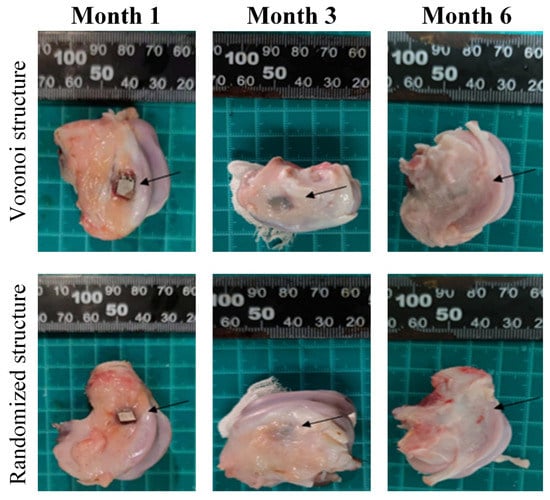
Figure 6.
Gross samples at each follow-up time point for the two porous designs (the black arrow indicates the implant location).
The representative results of gross anatomy are shown in Figure 6 at each follow-up time point for the two porous designs. At month 1, porous implants were stable and united with the host bone for both designs. The implants could not be easily pull out. There was a small amount of transparent soft tissue occasionally wrapped around the implant, and there was no obvious callus formation around the implant. At month 2, porous implants were stable and united with the host bone for both designs. The implants could not be easily pulled out. Besides, more soft tissues were found around the implant compared with month 1. At month 3, all the implant surfaces had been wrapped by new soft tissue. Generally, no obvious difference was found between the two porous designs.
Figure 7 illustrates the micro-CT images for the two porous designs during different follow-up periods (1 month, 3 months, and 6 months). The porous implants of the animals in each group were in good shape without obvious deformation, and new bone tissue had grown into the gaps on the pore surface of the implants. Gaps became fuzzy at month 3 and almost disappeared at month 6 for both structures. No significant difference was observed between the Voronoi structure group and the randomized structure group at each follow-up time point. Due to the strong metal artifacts and irregular shapes of the porous implants, it is impossible to accurately observe and evaluate the bone ingrowth and osseointegration between the implant and the bone. Therefore, histopathological observation was conducted to conduct a semi-quantitative analysis on the area of new bone tissue in the porous implants.
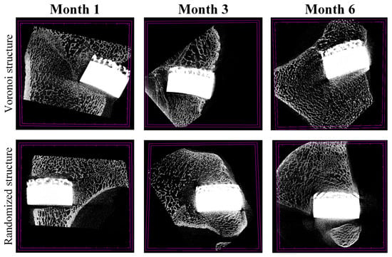
Figure 7.
Micro-CT of the Voronoi structure group and the randomized structure group at each follow-up time point.
Pathological observation and analysis are shown in Figure 8. In the methylene blue-acid fuchsin staining, crimson areas indicate the new bone tissue. In Figure 8, the fuchsin area indicates bone tissue, and the black area indicates the implant. At month 1, immature needle-shaped bone trabeculae were found around the implant. Besides, the surface of the implant was wrapped by fibrous tissues, with a small amount of new bone trabeculae adhering to the surface. At month 3, the number of immature needle-shaped woven bones around the implants increased with the prolongation of the time point, and some bone tissues began to have a central canal structure. In addition, the disorderly arranged collagen fibers began to be remodeled gradually, and the bone connection started to establish itself between the new bone tissue and the old bone tissue. At month 6, new bone tissue can be seen around the implant, and bone plate structures were observed in some bone tissue. The new bones basically formed a bony connection with the old bones. From month 1 to month 6, the Voronoi structure group exhibited a roughly larger number of new bones compared to the randomized structure group.
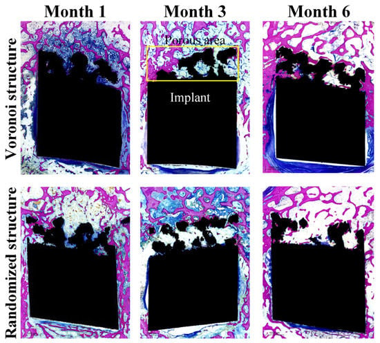
Figure 8.
Pathological observation of the Voronoi structure group and the randomized structure group at each follow-up time point (the yellow box indicates the porous area of the implant).
Histomorphometry was further conducted to measure the growth of new bone at the interface of bone particles using Image Pro Plus 6.0 software (Version 6.0, Taiwan, China) based on pathological observations. The area of the porous surface of the implant in the entire slice was defined as the total interest area S1 (the whole area of the yellow box in Figure 8), and the total area of bone tissue ingrown in the S1 area was measured and defined as S2 (the fuchsin area in the yellow area), and the bone ingrowth ratio of the porous implant was defined as S2 divided by S1. Table 3 shows the bone ingrowth ratios for all nine Beagle dogs at three different follow-up periods.

Table 3.
Bone ingrowth ratios (%) for all nine Beagle dogs at three different follow-up periods.
From Table 3, it can be seen that the bone ingrowth ratio did not have an obvious increasing trend from month 1 to month 6 for both porous designs. Such controversial findings could be explained with the help of the definition of bone ingrowth ratios. In this study, the bone ingrowth ratio was defined to evaluate the bone ingrowth into the porous structures instead of the whole bone defects. Apart from the new bones in the porous structures, new bones were also formed and found between the gaps of the implant and the bone defects, which can be easily seen from Figure 6. The ingrowth of total new bones in and around the whole implant followed an increasing trend with time.
Due to the existence of individual differences among dogs, the standard deviation does not provide valuable information for the bone ingrowth comparison between the two porous designs. Therefore, only comparisons between average values were considered in this study. Generally, based on the data from month 1 to month 6 (Table 3), the Voronoi structure exhibited a higher bone ingrowth ratio compared to the randomized structure. In other words, the Voronoi structure is more conducive to bone ingrowth.
4. Discussion
4.1. The Effect of Size and Boundary Conditions on the Mechanical Properties
The human cancellous bone has a strength range of 1.5–38 MPa. The cortical bone has a strength range of 35–283 MPa [37,38]. In this study, the 3D printed Voronoi structure had a tensile strength of 169.29 MPa, while that of the randomized structure was 72.72 MPa, which was at the same strength level as the cortical bone. Besides, the porous Trabecular-like structure studied by others also found that the 3D printed Ti-6Al-4V scaffolds with porosities of 48.83–74.28% presented a satisfying mechanical performance with an apparent strength range of 44.9–237.5 MPa [27], which exhibited similar mechanical properties to the results in this paper. However, no further investigations were carried out for different sample sizes of different porous structures.
In real-world applications such as porous implants, due to the limited design space in the human body, porous structures are commonly designed with finite cell sizes. In addition to the relative density mentioned in the above Gibson–Ashby model [35,36], the size effect, which is introduced by the boundary conditions, is also an important design factor. It is common in the field of porous structure modeling to extract an “effective” property—a property that represents a homogenized behavior without explicitly modeling the detail of the structures. This is an elegant concept but introduces some practical challenges in its implementation. Inherent in the assumption is that this property, modulus, for example, is equivalent to a continuum property valid at every material point. The reality is that the extraction of this property is strongly dependent on the number of unit cells involved in the experimental characterization process. When considering the size effects, each individual unit cell and strut will be different from the others, which decreases the prediction accuracy of the classical Gibson–Ashby model. This could briefly explain the strength difference between the two porous structures with the same relative density in Section 3.2.
To further illustrate the size and boundary effects of the two porous designs on their mechanical properties, the stress distributions of the two porous designs were visualized using the finite element analysis (FEA) tool. The FEA simulations were performed with nTopology Simulation, which was selected due to its integration with nTopology, which was also used for the creation of the porous design. Static elastic mechanical analysis was performed for the elastic response of the structures. Convergence analysis was conducted to determine the final mesh size setting. FEA analysis for structures of both porous designs was carried out using Ti6Al4V variables (Young’s modulus of 114 GPa, Poisson ratio of 0.34). The porous model and boundary conditions for the simulation are shown in Figure 9a. Since the focus of the FEA study was to illustrate the presence of the boundary effect and the difference between the boundary effects of the two different porous designs, no attempt was made to determine the optimal sample size and loading conditions. Therefore, the size of the porous structure was randomly set to 15 mm × 15 mm × 5 mm. In addition, linear elastic responses were investigated in this paper. At the linearly elastic stage, there is a linear positive correlation between the loading value and the corresponding maximum stress value. So, a force loading (1000 N) was randomly selected and applied to the top of the model for the evaluation of the stress concentration and stress distribution under the same loading condition. The locations with the top three maximum stresses were marked and overlaid within single structural graphs. Figure 9b,c exhibits the stress distributions and structural deformations of two different designs. The results clearly illustrate that the presence of the boundary exhibited different boundary-affected regions between different designs. Ideally, based on the Ashby-Gibson model, the porous structures should show uniformly distributed stress among unit cells regardless of the boundary and the interior. However, from Figure 9b, it can be seen that the Voronoi structure seemed to be less affected by the boundary conditions, with a relatively uniform stress distribution throughout the whole structure. The maximum stress occurred randomly in the middle area of the structure, as indicated by the red circle in Figure 9b. In the randomized structure, it is quite obvious that the stress was concentrated on the top and bottom boundaries. In addition, it is notable that there was an obvious difference in the maximum stress level between the two designs. Under the same loading condition, the randomized structure had a maximum stress that was more than twice that of the Voronoi structure. By converting the maximum stress to the tensile strength, we can know that the simulated tensile strength of the Voronoi structure would be twice that of the randomized structure. Reviewing the data from Table 2, the tensile strength of the Voronoi structure was 2.7 times that of the randomized structures. Overall, the simulation prediction matches the experimental results of the tensile strength shown in Table 2. Generally, the FEA results demonstrate the presence of the boundary effect of the porous structures and its difference between porous geometries.
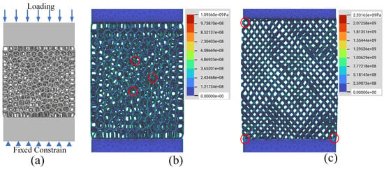
Figure 9.
(a) Loading conditions of porous structures; (b) FEA results for the Voronoi structure; (c) FEA results for the randomized structure. (The red circles indicate the maximum stress locations in porous structures).
Based on the above FEA analysis, it can be concluded that the porous structures exhibited different reactions to the applied loadings due to the existence of boundary and size effects. To further investigate the boundary and size effects, porous structures with different heights were fabricated by the EBM process. In this study, five heights (2.5 mm, 5 mm, 10 mm, 15 mm, and 20 mm) were fabricated, as shown in Figure 10a. The compression tests were executed in the laboratory at room temperature. The load direction was the same as the direction of additive manufacturing and, thus, perpendicular to the printed layers. During the testing, the samples were placed between two steel tool plates. The specimens were loaded by remote displacement, and the velocity of deformation was set to 1 mm/min, which corresponds to the ISO 13314:2011 standard shown in Figure 10b. The stress was obtained from the applied force obtained by the load cell. The strain–stress curves are shown in Figure 10c,d for the Voronoi and randomized structures, respectively. The compressive strength of the structure was defined as the maximum stress level before the occurrence of the first failure.
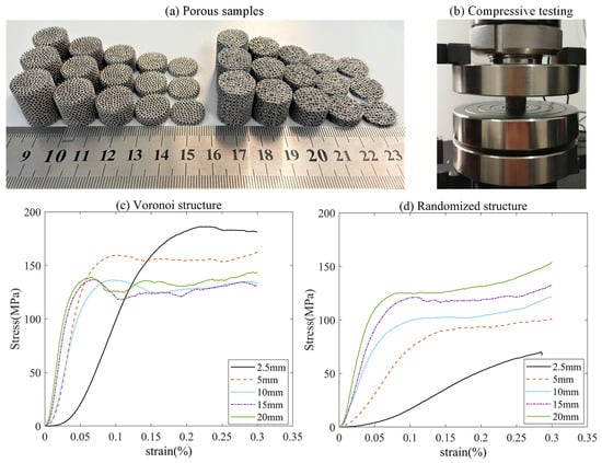
Figure 10.
(a) Fabricated porous samples with different heights; (b) loading conditions during the compressive test; (c) strain–stress curves for Voronoi structures; (d) strain–stress curves for randomized structures.
The stress–strain curves were typical for porous structures, including the linear increase in stress with strain and a plateau region with fluctuating stresses. For the two porous designs, the linear increase regions of the strain–stress curves were similar. However, when it comes to the fluctuating regions, there is an obvious difference. The randomized structures exhibited smooth and stable fluctuating regions, while the Voronoi structures showed a relatively larger fluctuation. This might be attributed to the size and boundary effects on stress distribution for the two designs. Based on our previous studies [39,40], higher stress concentration level (randomized structure) might lead to a lower stress peak after the linear stage and a following stable failure propagation. For the porous structures with lower stress concentration level (the Voronoi structure), the compressive response tended to be a step-by-step (or strut-by-strut) failure propagation, which led to a saw-toothed curve. The initial failure in the Voronoi structure occurred at the strut with the maximum stress. Upon initial failure, the failed strut was no longer contributing to the load bearing of the structures, and the stresses in the remaining Voronoi structure would be redistributed. Further increments in the applied loading would result in the failure of other struts within the structure. This progressive failure process continues until complete failure [40].
As illustrated in Figure 10c,d, both structures exhibited obvious different strain–stress curves when the sample height varied from 2.5 mm to 20 mm. Moreover, both the compressive strength and Young’s modulus had different tendencies with different sample sizes. The detailed relationships between the mechanical properties and the sample height are shown in Figure 11. It is obvious that the Voronoi structures had a higher compressive strength and Young’s modulus than the randomized structures, which matches the lower stress concentration caused by the boundary effect shown in Figure 9. When the sample height varied from 2.5 mm to 20 mm, the compressive strength of the Voronoi structures exhibited a decreasing tendency, while the randomized structures showed an increased tendency (Figure 11a). The compressive strength tended to stabilize when the sample height increased to 15 mm. On the other hand, Young’s modulus tended to increase with the increase in sample height for both the Voronoi structures and the randomized structures. Overall, Young’s modulus appears to stabilize when the sample height goes to 15 mm. Therefore, it can be concluded from Figure 11a,b that the mechanical properties tend to converge to consistent values when the sample height increases sufficiently, even though different porous structures may have different characteristic stabilization sample heights. In general, the size and boundary effects could directly affect the mechanical properties of porous structures, and different pore geometries tend to exhibit different reactions to these effects.
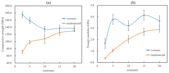
Figure 11.
Relationships between the mechanical properties and the sample height: (a) compressive strength; (b) Young’s modulus.
4.2. The Effect of Porous Geometry on the In Vivo Performances
In this study, the in vivo assessment demonstrated that the EBM-fabricated Ti-6Al-4V porous implants based on the Voronoi structure had favorable osteogenic capability compared to the randomized structure in orthopedic applications, as shown in Section 3.3. We can draw a preliminary conclusion that porous structures based on the Voronoi design can provide a better bone ingrowth performance than those based on a randomized design.
The effect of porous structures on bone ingrowth has been a focus of research in bone tissue bioengineering. It is widely known that the design parameters such as pore size, porosity, and pore geometry of porous structures all have a crucial impact on the bone ingrowth effect. These design parameters of porous structures could all affect in vivo performances in different ways. The pore size can affect nutrient transportation, oxygen exchange, and metabolite removal in porous structures in a microenvironment. Additionally, it is also closely related to cell adhesion, migration, proliferation, differentiation, angiogenesis, and cartilage mineralization. The porosity of the porous structures also has an important place for cell penetration and migration, which further affects the bone’s integration ability. The change in pore geometry often leads to changes in physical parameters such as porosity and surface area, which will indirectly change fluid flow rate, fluid shear force, and permeability, and ultimately affect cell adhesion, migration, proliferation, and differentiation.
To investigate the mechanism of porous geometry effects on in vivo performance, a detailed analysis of the pore morphology features was conducted. Figure 12 exhibits the pore morphology features for the two porous geometries. Figure 12a,b,d,e shows the pore geometry from the bone growth direction. These pictures indicate that both structures had stochastically distributed struts. The Voronoi structure exhibited a more regular pore shape, while the randomized structure showed a relatively irregular pore shape. By comparing the feathers in Figure 12b,e, we can see that the Voronoi structure obviously had a higher transparency compared to the randomized structure. Detailed pore morphology features in bone growth direction were illustrated in Figure 12c,f. From the bone growth direction, the Voronoi structure exhibited a more smooth, regular, radially oriented bone growth path compared to the randomized structure. In addition, recalling the results of the morphological characterization of the two porous structures in Section 3.1, we can also see that there are differences in the pore size distribution between the two designs. The randomized structure had a wider pore size distribution, varying from 507 μm to 953 μm, while the Voronoi structure exhibited homogenous pore sizes, varying from 608 μm to 858 μm.
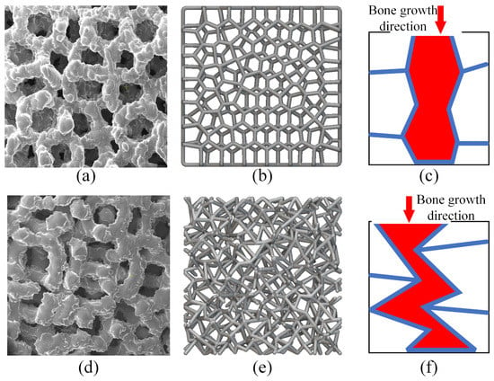
Figure 12.
Designed and fabricated pore geometry of the two porous designs: (a) fabricated Voronoi structure; (b) designed Voronoi structure; (c) bone growth direction of Voronoi structure; (d) fabricated randomized structure; (e) designed randomized structure; (f) bone growth direction of randomized structure.
Based on the above cognition and the pore morphology features, the better in vivo performance of Voronoi structures could be attributed to the following reasons:
- (a)
- Radially oriented pore geometry. A radially oriented pore can integrate the surrounding tissue better than a random pore. Additionally, at the same time, cells can migrate deeper into the porous structures, so capillaries can grow deeper with less barrier. Moreover, a mixed tissue of fiber and fibrocartilage can be formed in porous structures with radially oriented pores, while only fibrous tissue can be formed in porous structures with irregular pores. Generally, the radially oriented pores can facilitate cell ingrowth, longitudinal alignment of cells, and integration with the surrounding tissue, and may be suitable for in vivo applications [41]. Similar findings were also discussed in the research of Matsugaki [42] and Ishimoto [43]. They designed a honeycomb tree structure with through-pores and a grooved substrate for the spinal cages. Such a grooved through-pore structure was similar to the radially oriented pore geometry in our study. It was found in their research that such a through-pore honeycomb tree structure provided a direct scaffold that guided the bone matrix in its collagen and apatite orientation. Besides, such a design also exhibited greater strength at the bone interface compared with that of conventional and gold-standard box-type designs with autologous iliac bone grafts [42,43]. These findings can also prove the advantages of radially oriented pore geometry on bone ingrowth.
- (b)
- Homogenous pore size distribution. Porous structures with a high number of homogenous pore sizes allow faster colonization. Heterogeneous pore size distribution may also allow cell colonization, although the higher proportion of low pore size may reduce the diffusion of nutrients, oxygen, and cellular waste [44].
5. Conclusions
In this paper, we systematically investigated the mechanical properties and in vivo performance of two commonly used stochastic porous structures (Voronoi and randomized structures) fabricated by EBM. The EBM process could successfully fabricate two porous structures. The morphological characterization results show that the strut thickness of the two porous structures was consistent regardless of different pore geometries. The average porosity and pore size also did not show an obvious difference between the two designs. However, the pore size distribution of Voronoi structures was more consistent than that of randomized structures due to their different modeling approaches. It can be concluded that the porous structure modeled by the Voronoi tessellation algorithm can provide a more consistent pore geometry.
From the mechanical test results, it can be concluded that Voronoi structures exhibited higher tensile and shear strengths compared to the randomized structures, even though both structures exhibited similar pore geometries (pore size, strut thickness and porosity). Further analysis revealed that the better mechanical properties in Voronoi structures were attributed to the uniform stress distribution when considering the size and boundary effects. Furthermore, it was concluded that such an advantage became more obvious as the size of the porous structure got smaller (less than 10 mm). Therefore, it is evidenced that the boundary effect could also directly affect the strength of the porous structures in addition to intuitionistic factors such as porosity and pore size.
Based on the in vivo assessment of the two porous structures in a dog model, the Voronoi structure exhibited a higher bone ingrowth ratio compared to the randomized structure, although both pore geometries were stochastic with similar porosity and average pore size. Further analysis revealed that the radially oriented pore geometry and homogenous pore size distribution of the Voronoi structures are also the main reasons for better osseointegration. This finding could potentially promote better pore design in orthopedic applications.
Author Contributions
Conceptualization, Y.W. (Yan Wu), Y.W. (Yudong Wang), M.L., D.S., N.H., and W.F.; methodology, Y.W. (Yan Wu), Y.W. (Yudong Wang), M.L., D.S., N.H., and W.F.; software, Y.W. (Yan Wu); validation, Y.W. (Yan Wu), Y.W. (Yudong Wang), and D.S.; formal analysis, Y.W. (Yan Wu), Y.W. (Yudong Wang), M.L., and D.S.; investigation, Y.W. (Yan Wu), Y.W. (Yudong Wang), M.L., D.S., and W.F.; resources, Y.W. (Yan Wu), N.H., and W.F.; data curation, Y.W. (Yan Wu); writing—original draft preparation, Y.W. (Yan Wu); writing—review and editing, Y.W. (Yudong Wang), M.L., D.S., N.H., and W.F.; visualization, Y.W. (Yan Wu); supervision, W.F., M.L., and D.S.; project administration, D.S. and M.L.; funding acquisition, M.L. and W.F. All authors have read and agreed to the published version of the manuscript.
Funding
This research was funded by the National Innovation Center for High Performance Medical Devices (Shenzhen Science and Technology program: JSGG20211029095800001), the Shenzhen Institute of Advanced Technology, and Wuhan Mindray Scientific Co., Ltd. (Hubei Key Research and Development Plan: 2022BAD175).
Data Availability Statement
Data are unavailable due to privacy.
Conflicts of Interest
The authors declare no conflict of interest.
References
- Guo, A.X.; Cheng, L.; Zhan, S.; Zhang, S.; Xiong, W.; Wang, Z.; Wang, G.; Cao, S.C. Biomedical applications of the powder-based 3D printed titanium alloys: A review. J. Mater. Sci. Technol. 2022, 125, 252–264. [Google Scholar] [CrossRef]
- Schieker, M.; Mutschler, W. Bridging posttraumatic bony defects: Established and new methods. Unfallchirurg 2006, 109, 715–732. [Google Scholar] [CrossRef] [PubMed]
- Hussain, M.; Askari Rizvi, S.H.; Abbas, N.; Sajjad, U.; Shad, M.R.; Badshah, M.A.; Malik, A.I. Recent developments in coatings for orthopedic metallic implants. Coatings 2021, 11, 791. [Google Scholar] [CrossRef]
- Kowalski, S.; Gonciarz, W.; Belka, R.; Góral, A.; Chmiela, M.; Lechowicz, Ł.; Kaca, W.; Żórawski, W. Plasma-Sprayed Hydroxyapatite Coatings and Their Biological Properties. Coatings 2022, 12, 1317. [Google Scholar] [CrossRef]
- Soballe, K.; Hansen, E.S.; Brockstedt-Rasmussen, H.; Bunger, C. Hydroxyapatite coating converts fibrous tissue to bone around loaded implants. J. Bone Jt. Surg. Br. 1993, 75, 270–278. [Google Scholar] [CrossRef]
- Ferraris, S.; Spriano, S. Porous titanium by additive manufacturing: A focus on surfaces for bone integration. Metals 2021, 11, 1343. [Google Scholar] [CrossRef]
- Ferraris, S.; Warchomicka, F.; Ramskogler, C.; Tortello, M.; Cochis, A.; Scalia, A.; di Confiengo, G.G.; Keckes, J.; Rimondini, L.; Spriano, S. Surface structuring by Electron Beam for improved soft tissues adhesion and reduced bacterial contamination on Ti-grade 2. J. Mater. Process. Technol. 2019, 266, 518–529. [Google Scholar] [CrossRef]
- Akshaya, S.; Rowlo, P.K.; Dukle, A.; Nathanael, A.J. Antibacterial Coatings for Titanium Implants: Recent Trends and Future Perspectives. Antibiotics 2022, 11, 1719. [Google Scholar] [CrossRef]
- Hoskins, W.; Rainbird, S.; Holder, C.; Graves, S.E.; Bingham, R. Revision for aseptic loosening of highly porous acetabular components in primary total hip arthroplasty: An analysis of 20,993 total hip replacements. J. Arthroplast. 2022, 37, 312–315. [Google Scholar] [CrossRef]
- Niinomi, M. Recent metallic materials for biomedical applications. Metall. Mater. Trans. A 2002, 33, 477–486. [Google Scholar] [CrossRef]
- Sharif Ullah, A.M.M. Design for additive manufacturing of porous structures using stochastic point-cloud: A pragmatic approach. Comput.-Aided Des. Appl. 2018, 15, 138–146. [Google Scholar] [CrossRef]
- Yang, T.; Xie, D.; Li, Z.; Zhu, H. Recent advances in wearable tactile sensors: Materials, sensing mechanisms, and device performance. Mater. Sci. Eng. R Rep. 2017, 115, 1–37. [Google Scholar] [CrossRef]
- Lei, H.; Yi, T.; Fan, H.; Pei, X.; Wu, L.; Xing, F.; Li, M.; Liu, L.; Zhou, C.; Fan, Y.; et al. Customized additive manufacturing of porous Ti6Al4V scaffold with micro-topological structures to regulate cell behavior in bone tissue engineering. Mater. Sci. Eng. C 2021, 120, 111789. [Google Scholar] [CrossRef] [PubMed]
- Samourides, A.; Browning, L.; Hearnden, V.; Chen, B. The effect of porous structure on the cell proliferation, tissue ingrowth and angiogenic properties of poly (glycerol sebacate urethane) scaffolds. Mater. Sci. Eng. C 2020, 108, 110384. [Google Scholar] [CrossRef] [PubMed]
- Leong, K.F.; Cheah, C.M.; Chua, C.K. Solid freeform fabrication of three-dimensional scaffolds for engineering replacement tissues and organs. Biomaterials 2003, 24, 2363–2378. [Google Scholar] [CrossRef]
- Davoodi, E.; Montazerian, H.; Khademhosseini, A.; Toyserkani, E. Sacrificial 3D printing of shrinkable silicone elastomers for enhanced feature resolution in flexible tissue scaffolds. Acta Biomater. 2020, 117, 261–272. [Google Scholar] [CrossRef]
- Chu, C.; Graf, G.; Rosen, D.W. Design for additive manufacturing of cellular structures. Comput.-Aided Des. Appl. 2008, 5, 686–696. [Google Scholar] [CrossRef]
- Giannitelli, S.M.; Accoto, D.; Trombetta, M.; Rainer, A. Current trends in the design of scaffolds for computer-aided tissue engineering. Acta Biomater. 2014, 10, 580–594. [Google Scholar] [CrossRef]
- Wang, X.; Xu, S.; Zhou, S.; Xu, W.; Leary, M.; Choong, P.; Qian, M.; Brandt, M.; Xie, Y.M. Topological design and additive manufacturing of porous metals for bone scaffolds and orthopaedic implants: A review. Biomaterials 2016, 83, 127–141. [Google Scholar] [CrossRef]
- Simoneau, C.; Brailovski, V.; Terriault, P. Design, manufacture and tensile properties of stochastic porous metallic structures. Mech. Mater. 2016, 94, 26–37. [Google Scholar] [CrossRef]
- Ghouse, S.; Babu, S.; Nai, K.; Hooper, P.A.; Jeffers, J.R. The influence of laser parameters, scanning strategies and material on the fatigue strength of a stochastic porous structure. Addit. Manuf. 2018, 22, 290–301. [Google Scholar] [CrossRef]
- Yang, N.; Gao, L.; Zhou, K. Simple method to generate and fabricate stochastic porous scaffolds. Mater. Sci. Eng. C 2015, 56, 444–450. [Google Scholar] [CrossRef]
- Chen, Z.; Su, Z.; Ma, S.; Wu, X.; Luo, Z. Biomimetic modeling and three-dimension reconstruction of the artificial bone. Comput. Meth. Prog. Biomed. 2007, 88, 123–130. [Google Scholar] [CrossRef] [PubMed]
- Geng, X.; Li, Y.; Li, F.; Wang, X.; Zhang, K.; Liu, Z.; Tian, H. A new 3D printing porous trabecular titanium metal acetabular cup for primary total hip arthroplasty: A minimum 2-year follow-up of 92 consecutive patients. J. Orthop. Surg. Res. 2020, 15, 383. [Google Scholar] [CrossRef] [PubMed]
- Dall’Ava, L.; Hothi, H.; Henckel, J.; Di Laura, A.; Shearing, P.; Hart, A. Comparative analysis of current 3D printed acetabular titanium implants. 3D Print Med. 2019, 5, 15. [Google Scholar] [CrossRef] [PubMed]
- Yang, J.; Cai, H.; Lv, J.; Zhang, K.; Leng, H.; Sun, C.; Wang, Z.; Liu, Z. In vivo study of a self-stabilizing artificial vertebral body fabricated by electron beam melting. Spine 2014, 39, 486–492. [Google Scholar] [CrossRef]
- Liang, H.; Yang, Y.; Xie, D.; Li, L.; Mao, N.; Wang, C.; Tian, Z.; Jiang, Q.; Shen, L. Trabecular-like Ti-6Al-4V scaffolds for orthopedic: Fabrication by selective laser melting and in vitro biocompatibility. J. Mater. Sci. Technol. 2019, 35, 1284–1297. [Google Scholar] [CrossRef]
- Du, Y.; Liang, H.; Xie, D.; Mao, N.; Zhao, J.; Tian, Z.; Wang, C.; Shen, L. Design and statistical analysis of irregular porous scaffolds for orthopedic reconstruction based on voronoi tessellation and fabricated via selective laser melting (SLM). Mater. Chem. Phys. 2020, 239, 121968. [Google Scholar] [CrossRef]
- Lei, H.Y.; Li, J.R.; Xu, Z.J.; Wang, Q.H. Parametric design of Voronoi-based lattice porous structures. Mater. Des. 2020, 191, 108607. [Google Scholar] [CrossRef]
- Deering, J.; Dowling, K.I.; DiCecco, L.A.; McLean, G.D.; Yu, B.; Grandfield, K. Selective Voronoi tessellation as a method to design anisotropic and biomimetic implants. J. Mech. Behav. Biomed. Mater. 2021, 116, 104361. [Google Scholar] [CrossRef]
- Sharma, N.; Ostas, D.; Rotar, H.; Brantner, P.; Thieringer, F.M. Design and additive manufacturing of a biomimetic customized cranial implant based on voronoi diagram. Front. Physiol. 2021, 12, 647923. [Google Scholar] [CrossRef]
- Efstathiadis, A.; Symeonidou, I.; Tsongas, K.; Tzimtzimis, E.K.; Tzetzis, D. Parametric Design and Mechanical Characterization of 3D-Printed PLA Composite Biomimetic Voronoi Lattices Inspired by the Stereom of Sea Urchins. J. Compos. Sci. 2022, 7, 3. [Google Scholar] [CrossRef]
- Wang, G.; Shen, L.; Zhao, J.; Liang, H.; Xie, D.; Tian, Z.; Wang, C. Design and compressive behavior of controllable irregular porous scaffolds: Based on voronoi-tessellation and for additive manufacturing. ACS Biomater. Sci. Eng. 2018, 4, 719–727. [Google Scholar] [CrossRef] [PubMed]
- Zhao, Z.; Li, J.; Yao, D.; Wei, Y. Mechanical and permeability properties of porous scaffolds developed by a Voronoi tessellation for bone tissue engineering. J. Mater. Chem. B 2022, 10, 9699–9712. [Google Scholar] [CrossRef] [PubMed]
- Gibson, L.J. Cellular solids. Mrs Bull. 2003, 28, 270–274. [Google Scholar] [CrossRef]
- Ashby, M.F.; Medalist, R.M. The mechanical properties of cellular solids. Metall. Trans. A 1983, 14, 1755–1769. [Google Scholar] [CrossRef]
- Morgan, E.F.; Bayraktar, H.H.; Keaveny, T.M. Trabecular bone modulus–density relationships depend on anatomic site. J. Biomech. 2003, 36, 897–904. [Google Scholar] [CrossRef]
- Gu, X.N.; Zheng, Y.F. A review on magnesium alloys as biodegradable materials. Front. Mater. Sci. China 2010, 4, 111. [Google Scholar] [CrossRef]
- Wu, Y.; Yang, L. Elastic and failure characteristics of additive manufactured thin wall lattice structures with defects. Thin-Walled Struct. 2021, 161, 107493. [Google Scholar] [CrossRef]
- Wu, Y.; Yang, L. The effect of unit cell size and topology on tensile failure behavior of 2D lattice structures. Int. J. Mech. Sci. 2020, 170, 105342. [Google Scholar] [CrossRef]
- Brouwer, K.M.; Daamen, W.F.; van Lochem, N.; Reijnen, D.; Wijnen, R.M.; van Kuppevelt, T.H. Construction and in vivo evaluation of a dual layered collagenous scaffold with a radial pore structure for repair of the diaphragm. Acta Biomater. 2013, 9, 6844–6851. [Google Scholar] [CrossRef] [PubMed]
- Matsugaki, A.; Ito, M.; Kobayashi, Y.; Matsuzaka, T.; Ozasa, R.; Ishimoto, T.; Takahashi, H.; Watanabe, R.; Inoue, T.; Yokota, K.; et al. Innovative design of bone quality-targeted intervertebral spacer: Accelerated functional fusion guiding oriented collagen and apatite microstructure without autologous bone graft. J. Spine 2023, 23, 609–620. [Google Scholar] [CrossRef] [PubMed]
- Ishimoto, T.; Kobayashi, Y.; Takahata, M.; Ito, M.; Matsugaki, A.; Takahashi, H.; Watanabe, R.; Inoue, T.; Matsuzaka, T.; Ozasa, R.; et al. Outstanding in vivo mechanical integrity of additively manufactured spinal cages with a novel “honeycomb tree structure” design via guiding bone matrix orientation. J. Spine 2022, 22, 1742–1757. [Google Scholar] [CrossRef]
- Perez, R.A.; Mestres, G. Role of pore size and morphology in musculo-skeletal tissue regeneration. Mater. Sci. Eng. C 2016, 61, 922–939. [Google Scholar] [CrossRef] [PubMed]
Disclaimer/Publisher’s Note: The statements, opinions and data contained in all publications are solely those of the individual author(s) and contributor(s) and not of MDPI and/or the editor(s). MDPI and/or the editor(s) disclaim responsibility for any injury to people or property resulting from any ideas, methods, instructions or products referred to in the content. |
© 2023 by the authors. Licensee MDPI, Basel, Switzerland. This article is an open access article distributed under the terms and conditions of the Creative Commons Attribution (CC BY) license (https://creativecommons.org/licenses/by/4.0/).