Article

Simulation of Cross Wedge Rolling and Hot Extrusion-Combined Forming Process for Axle Sleeve

1
School of Mechanical Engineering, University of Science and Technology Beijing, Beijing 100083, China
2
Beijing Laboratory of Metallic Materials and Processing for Modern Transportation, University of Science and Technology Beijing, Beijing 100083, China
*
Author to whom correspondence should be addressed.
Metals 2023, 13(6), 1017; https://doi.org/10.3390/met13061017
Submission received: 27 April 2023 / Revised: 13 May 2023 / Accepted: 15 May 2023 / Published: 25 May 2023
(This article belongs to the Special Issue Rolling and Extrusion of Metals)

Abstract

:
In this paper, an axle sleeve is formed through a combined cross wedge rolling (CWR) and hot extrusion process, and the combined forming process is simulated via finite element analysis software Deform-3D. The forming mechanism is revealed by analyzing the stress and strain distribution, the temperature variation and the metal flow law of the workpiece during CWR and hot extrusion. Combined with CWR and hot extrusion forming experiments, the feasibility of a combined rolling and extrusion process to produce an axle sleeve is verified. It has been proven that the outer steps of the axle sleeve produced through the rolling extrusion composite process are well formed, the flange extrusion cavity is full, the metal streamline is continuous, the axis of the inner hole does not easily deviate, the product quality is good and the production efficiency is high.

1. Introduction

An axle sleeve is an important part of the drive axle of heavy truck and construction machinery. It needs to withstand the weight of the vehicle body and goods, as well as various complex alternating loads caused by changes in road environment together with the axle housing during operation. Therefore, the quality of the axle sleeve is of great significance for driving safety. In general, a process that does not damage the continuity of the metal structure is used to form the axle sleeve to ensure its mechanical properties. Hot extrusion is commonly used to produce axle sleeves. Hansson et al. [1] established a finite element model of hot extrusion used on glass-lubricated stainless-steel tubes, and they used two different regression models to determine the model parameters that were most important for the response of the extrusion force, namely the initial temperature of the billet. Zhou et al. [2] and Xv et al. [3] designed a hot extrusion forming process scheme for the axle sleeve and used finite element software to analyze the influence of the billet heating temperature, the punch extrusion speed and the preheating temperature of the die on the forward extrusion forming effect and forming load, verifying the feasibility of hot extrusion forming the axle sleeve. Zhang et al. [4] established a finite element model of the extrusion process of the complex hollow aluminum profile and analyzed the metal flow at each stage. Negendank et al. [5] demonstrated the feasibility of extrusion forming aluminum tubes with axial gradient wall thickness by using an axially movable stepped mandrel. Gattmah et al. [6] conducted finite element simulation of the hot extrusion process of a hollow tube and studied the effects of process parameters, initial billet temperature, ram displacements, reductions in area, semi-die angle and friction coefficient on the forming process. It is found that reductions in the area and friction coefficient have significant impacts on the surface temperature and the extrusion force. Li et al. [7] analyzed the influence of process parameters on the axial length deviation of the tube end of the axle sleeve semi-finished product of heavy trucks formed via extrusion using response surface methodology. It is found that the axial length deviation of the tube end shows a decreasing trend with an increase in the extrusion speed and the connecting belt thickness. Compared with other processes, the part produced using hot extrusion has a reasonable metal streamline, dense metal structure and high fatigue life. However, this technology also has drawbacks, such as low material utilization and complex production process.
CWR is an advanced forming process for shaft parts with high efficiency, high material utilization rate and good forming performance. It can accurately form a multi-step shaft with a continuous metal streamline. At present, significant progress has been made in the research on cross wedge rolling for hollow shafts. Yang et al. [8,9] studied the causes of ovalization of the hollow shaft in CWR. It is found that the radial and axial flow of the metal does not match in the forming process and some metal flows, laterally resulting in ovalization of the rolled parts. The relationship between process parameters and the ovality of rolled parts was studied, and the prediction model for the ovality of rolled parts was established. Ma et al. [10,11] used the finite element method to design and improve the die for CWR of the axle sleeve. The hole expansion at the knifing position of the workpiece was analyzed and resolved through mandrel compensation. The evolution of the microstructure during CWR of the axle sleeve was studied, and the influence of process parameters on the grain size and uniformity was analyzed. Huo et al. [12] established a constitutive model, coupling the microstructure evolution and toughness damage of 25CrMo4 during CWR based on the continuous damage theory. They predicted the grain size and toughness damage of the material during CWR to optimize the process parameters. Huang et al. [13,14] studied the mechanism of the mandrel during the CWR process and the influence of the mandrel on the inner and outer surface diameter and the ovality of the hollow shaft through numerical simulation and experiment. Shen et al. [15] established a semi-empirical model based on the assumptions of volume consistency and ring deformation to predict the reduction process of the inner hole and the critical mandrel diameter of the hollow shaft during CWR. The influence of process parameters on the critical mandrel diameter was also studied. Lin et al. [16] proposed a novel method of flat-knifing cross wedge rolling with single guide for forming hollow shafts, which can effectively avoid the typical defects of hole expansion and knifing groove. Feng et al. [17,18,19] analyzed the influence of process parameters on the ellipticity of TC4 titanium alloy hollow shafts during cross wedge rolling and obtained accurately formed TC4 titanium alloy hollow parts. Moreover, the microstructure characteristics of TC4 titanium alloy hollow shafts during cross wedge rolling were revealed, and the effects of cross wedge rolling process parameters, with or without a mandrel and billet wall thickness on the phase transformation of titanium alloy, were studied. Shi et al. [20] studied the CWR process of hollow shafts with corrugated surfaces. The influence of mandrel diameter on stress, effective strain, temperature distribution, rolling force and torque was analyzed by using the finite element method. Combined with experimental results under different mandrel diameters, the influence of mandrel diameter on forming quality was discussed.
To improve the material utilization rate of axle sleeves and realize the near net forming, the combined process of CWR and hot extrusion is used to form the axle sleeve with large flange. The shaft part with multiple steps of the axle sleeve is formed via CWR, and the flange is formed using hot extrusion. The forming process is simulated and verified through the combination of finite element simulation and experiment. It provides theoretical guidance for the implementation of the composite process.

2. Forming Process Design for the Axle Sleeve

The geometry of an axle sleeve is shown in Figure 1a. It is a hollow stepped shaft with a large flange, whose flange diameter is 3-times that of the small-end diameter and has a long through-hole inside. The method of combining rolling and forging is adopted in this paper. The cylindrical billet is formed into the axle sleeve through three processes of punching, CWR and hot extrusion (as shown in Figure 1b–e). Firstly, the solid billet is upset and punched out of the inner hole, and the end of the outer surface is extruded into a cone shape for the next step of CWR. In the process of CWR, the billet with the end cone can be rolled into a rolled piece without a head. The asymmetry of rolled pieces is unfavorable for stable rolling in the CWR process. In the late stage of forming, rolling parts will move towards the big-end direction due to the imbalance of axial rolling force. Therefore, a small step is reserved at the end of the workpiece to balance the asymmetric axial force in the CWR process. At the same time, the small step also plays the role of auxiliary axial positioning in the hot extrusion process.

3. Numerical Simulation

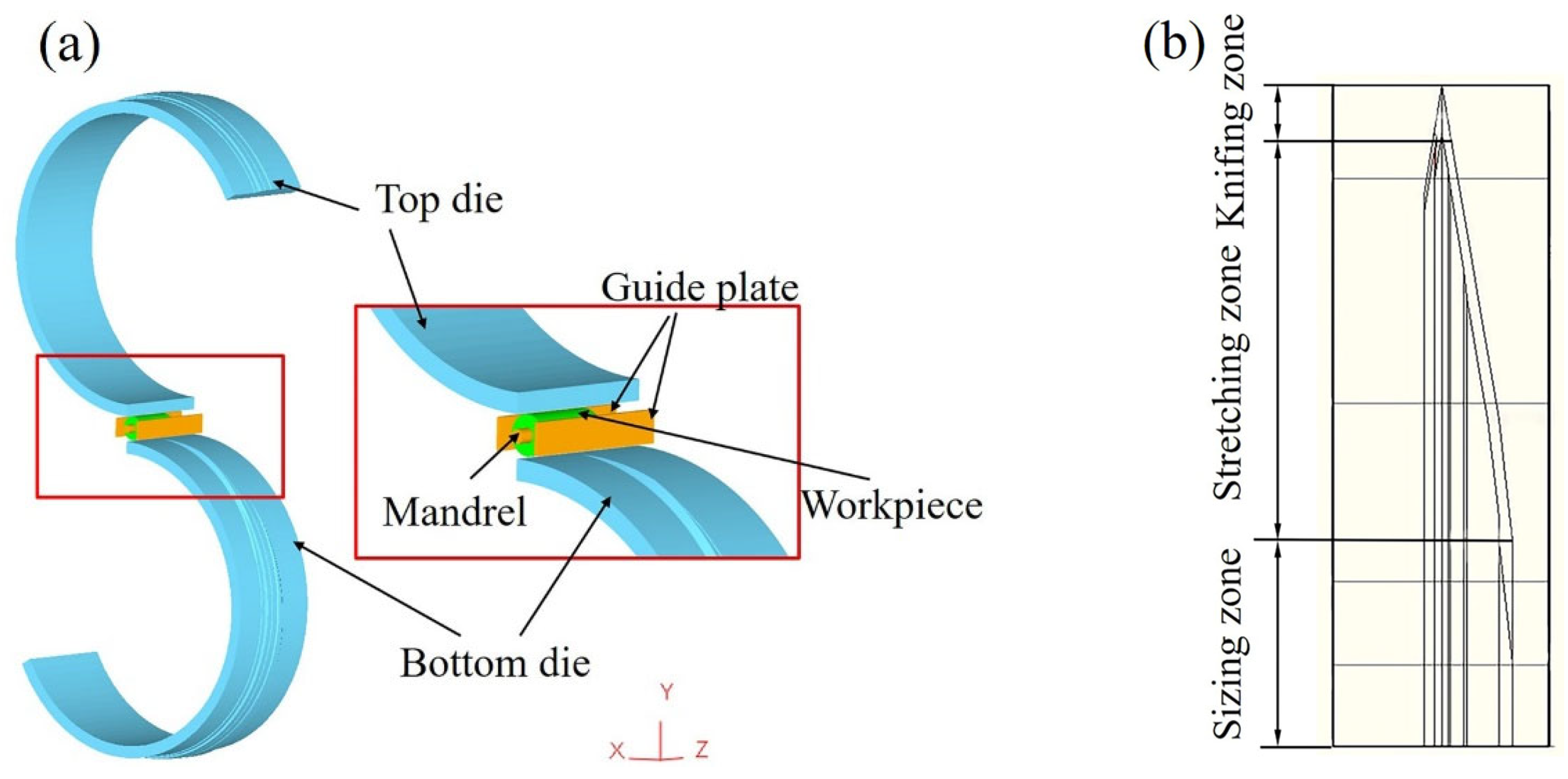
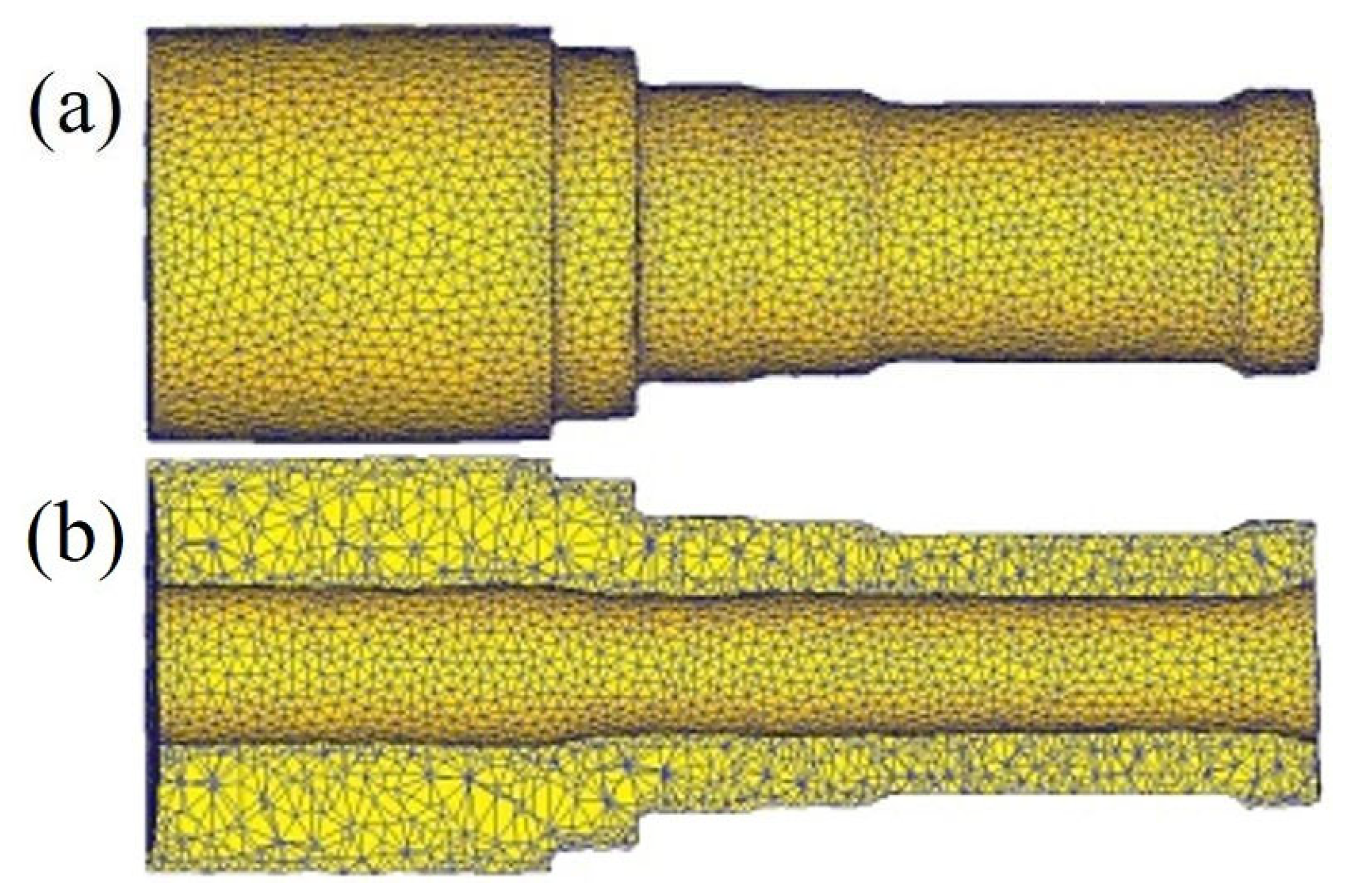
3.1. The Finite Element Model of CWR

The finite element model of CWR is shown in Figure 2a. There are top and bottom dies, workpiece, mandrel and guide plates in this geometric model. The flattened diagram of the cross wedge rolling tool is shown in Figure 2b. The CWR tool consists of a knifing zone, stretching zone and sizing zone. In the high-temperature CWR process, the workpiece has large plastic deformation, and the elastic deformation can be ignored, so the workpiece can be defined as a plastic body. The dies, guide plates and mandrel are defined as rigid bodies because of negligible elastic and plastic deformation. The workpiece material is 40Cr, which is commonly used in the production of axle sleeves and the suitable temperature range for forming is 800~1200 °C. Shear friction is adopted to define the contact relations of the workpiece, dies and guide plates, because shear friction is more suitable for the situation of high contact pressure. The simulation parameters are listed in Table 1.

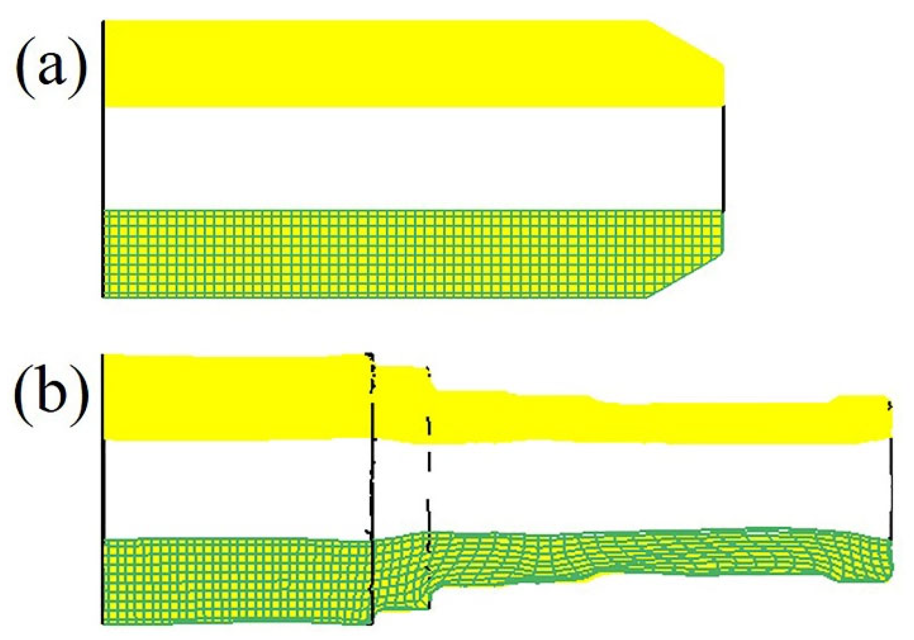
3.2. The Finite Element Model of Hot Extrusion

The flange is extruded via a hot extrusion process on the basis of the axle sleeve parts formed through CWR. The finite element model of hot extrusion is shown in Figure 3. The extruded part can be regarded as a rigid plastic body, and the dies of hot extrusion can be regarded as rigid bodies. Before using the hot extrusion dies, preheating is required to reduce the heat conduction between the extruded part and dies and extend the service life of the dies. The contact condition between the extruded part and the die is a constant coefficient shear friction model, and the friction factor is 0.1. The axle sleeve is a rotating body. To save the calculation time and increase the number of grids, 1/4 of the model is taken to carry out the simulation. The minimum element size of the tetrahedron is 0.5 mm, and the size ratio is 3. The simulation parameters are listed in Table 2.

4. Numerical Simulation Results

4.1. Numerical Simulation Analysis of CWR

4.1.1. The Forming Results

Figure 4 shows the FE simulation results of CWR of the axle sleeve. It can be seen from Figure 4a that the surface of the part is well formed, the steps are accurately formed and the axial and radial dimensions meet the process requirements. It can be seen from Figure 4b that the inner hole is well formed, and there is no deviation in the axis of the hole. Although there is a small size fluctuation in the inner hole locally, due to the combination of rolling and hot extrusion in this process, the next extrusion process will further refine the formed hole.
Figure 5 shows the internal grid of the rolled part before and after CWR. It can be seen that with a reduction in the axle diameter, the rolled part extends axially, and the grid is elongated axially. In the rolling process, the grid lines are always continuous, especially in the positions where the diameter changes. The grids deform with the shape of the steps, but they still remain continuous, which indicates that the parts formed via CWR have continuous metal streamline, which can ensure the excellent mechanical properties of the rolled part.

4.1.2. Analysis of Stress Distribution

Figure 6 shows the stress distribution on the cross section of the wedge starting position in the knifing zone. It can be seen that all the stress is distributed symmetrically about the center of the cross section. In the local area where the workpiece contacts with the dies, due to the metal flow being blocked, the transverse stress, radial stress and axial stress are all large compressive stress, which can reach 350~500 MPa. From the contact point to the center of the cross section, the compressive stress is fan-shaped diffusion distribution and gradually decreases. On the left and right sides of the workpiece, the stress in all directions of the workpiece is all little tensile stress on the outer surface, while compressive stress is present in the inner surface. This is because the workpiece is extruded by the dies in the knifing zone and begins to expand laterally and axially. The cross section begins to appear elliptical, causing the inner hole to be compressed and the outer surface to be stretched in the non-deformed area. Effective stress can reflect the intensity of stress. It can be seen from Figure 6d that the maximum of the effective stress appears in the part where the workpiece contacts with the wedge of the dies and gradually decreases inward.
Figure 7 shows the stress distribution on the longitudinal section in the knifing zone of CWR. It can be seen from Figure 7a–c that in the local area where the workpiece contacts with the dies, the transverse stress, radial stress and axial stress are all large compressive stress. The farther away from the contact area, the smaller the compressive stress value. In the area where the workpiece contacts with the mandrel, due to the support of the mandrel, the inner surface of the workpiece is also subjected to compressive stress. It can be seen from Figure 7d that the effective stress in the contact area between the workpiece and the dies is the largest, up to 250 MPa. Most areas of the workpiece have not been squeezed by the dies, and the effective stress is 0.
Figure 8 shows the stress distribution on the cross section at the wedge starting position in the stretching zone of CWR. The stress of the workpiece is distributed symmetrically about the center of the cross section. The maximum stress, which is compressive stress, occurs in the local area where the workpiece contacts with the dies. Their value can reach 550 MPa~800 MPa and gradually decreases inward. Because the inner hole of the workpiece is supported by the mandrel, the stress in all directions is compressive stress in the local area where the workpiece contacts with the mandrel. In the non-deformed area on both sides of the workpiece, due to the pulling effect of the metal in the deformed area, the transverse stress, radial stress and axial stress of the workpiece are all tensile stress. Compared with the knifing zone, the axial tensile stress and transverse tensile stress increase in the stretching zone, but the axial tensile stress is larger, indicating that the axial extension of the metal in the stretching zone is dominant. It can be seen from Figure 8a that the inner hole of the workpiece is supported by the mandrel and shows transverse compressive stress in the contact area with the mandrel. The metal in region A flows laterally, resulting in additional transverse tensile stress. It can be seen from Figure 8a–c that the transverse stress, radial stress and axial stress at the position of maximum stress on the outer wall of the rolled part are about −570, −750 and −530 MPa, respectively, and the transverse stress, radial stress and axial stress at the position of maximum stress on the inner wall are about −180, −350 and −200 MPa, respectively. The area between the die and the mandrel becomes a high-compressive-stress deformation area, which is beneficial to improve the quality and performance of the rolled part. Figure 8d shows the effective stress distribution. It can be seen that the maximum value of the effective stress occurs in the area where the workpiece contacts with the dies, and its value can reach 350 MPa. The farther away from the contact area, the smaller the effective stress.
Figure 9 shows the stress distribution on the longitudinal section in the stretching zone. It can be seen that the maximum compressive stress of the stress in all directions on the outer surface appears in the contact area between the inclined wedge surface of the roller and the workpiece and gradually decreases towards the center. It can be seen from Figure 9c that due to the axial flow of external metal, the metal inside the workpiece is pulled, and additional axial tensile stress is generated inside the workpiece. Due to the influence of friction force, the local area where the workpiece contacts with the dies and the mandrel produces relatively small axial compressive stress. Figure 9d shows the distribution of effective stress. It can be seen from the figure that the maximum effective stress in the stretching zone occurs in the area where the workpiece contacts with the dies. The stress value is much larger than that of the knifing zone, so the stretching zone is the main deformation stage of CWR.

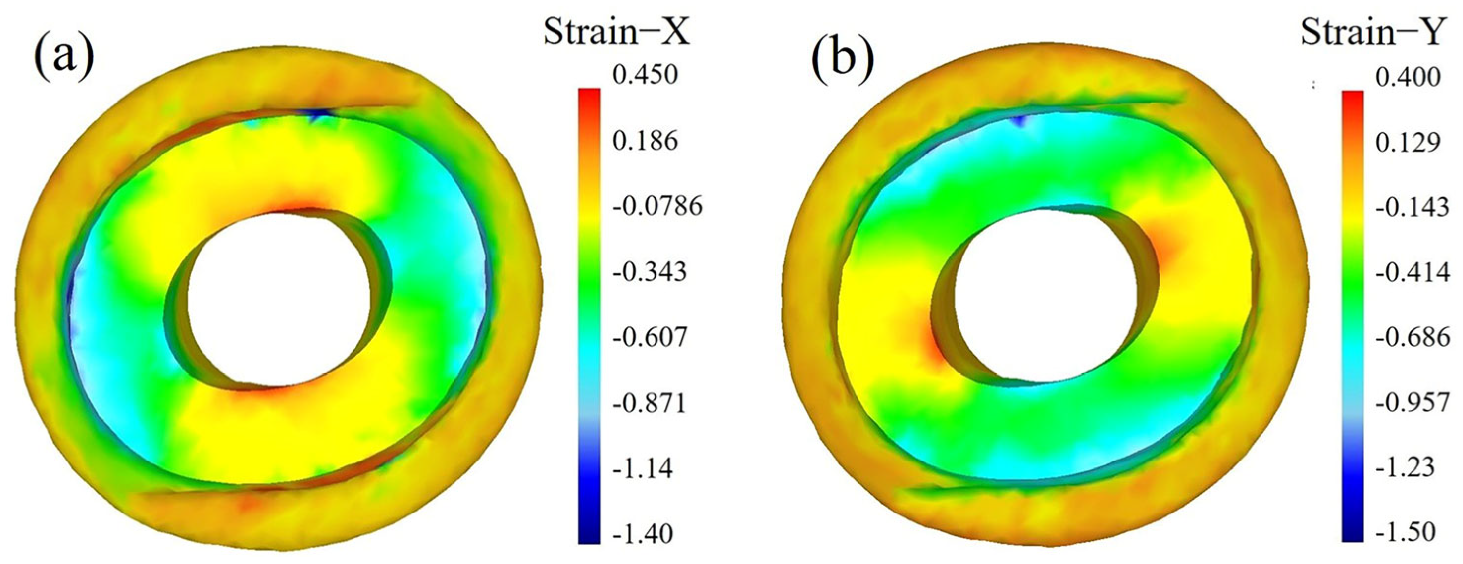
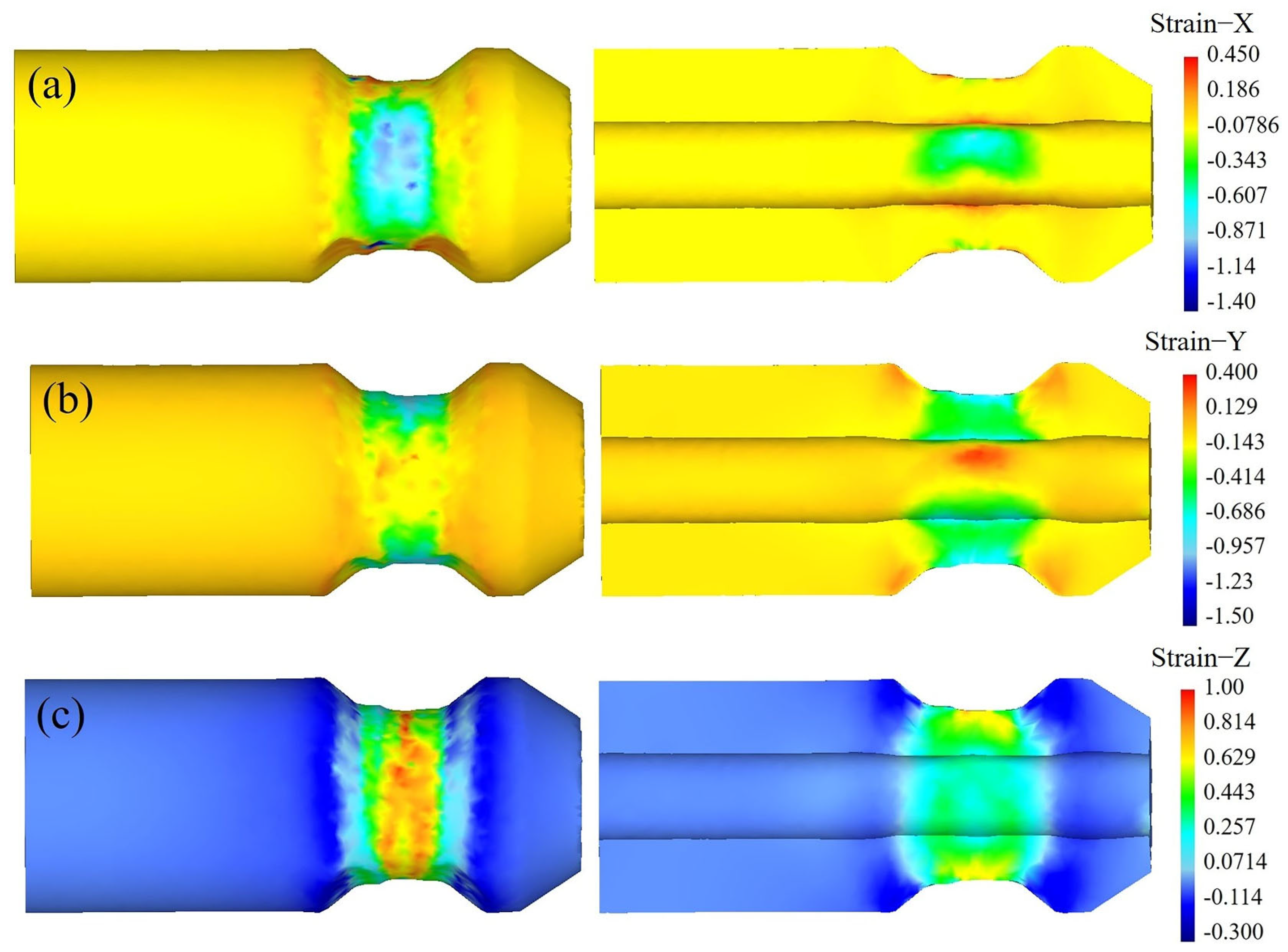
4.1.3. Analysis of Strain Distribution

As the stretching zone is the main deformation stage in the CWR process, the strain distribution on the cross section of the axle sleeve during the stretching zone is analyzed, as shown in Figure 10. It can be seen that the workpiece is compressed in the radial direction and the metal radial flow is blocked, causing some metal to flow laterally, resulting in ovalization of the cross section of the workpiece. Therefore, the radial strain of the workpiece is mainly compressive strain, and the maximum value appears in the local area where the workpiece contacts with the dies and mandrel. The transverse tensile strain mainly occurs in the area near the minor axis of the ellipse, while the transverse compressive strain is relatively large at the long axis of the ellipse because the metal is accumulated here. Figure 10c shows the distribution of axial strain on the cross section in the stretching zone. It can be seen that the axial strain of the cross section of the workpiece is mainly tensile strain, and the maximum tensile strain is concentrated on the outer surface of the workpiece, gradually decreasing from the outside to the inside. This is because under the action of the die-forming surface, the axial flow velocity of the metal on the outer surface is greater than that of the metal on the inner surface, and the axial flow amount is large, so the axial tensile strain on the outer surface is larger.
Figure 11 shows the strain distribution on the longitudinal section in the stretching zone of CWR. Figure 11a shows the distribution of transverse strain. The metal flows laterally in the local area where the workpiece contacts with the dies and mandrel, resulting in transverse tensile deformation, while the non-contact area experiences transverse compressive deformation due to metal accumulation. Figure 11b shows the distribution of radial strain. It can be seen that the maximum radial compressive strain occurs in the local area where the workpiece contacts with the dies and gradually decreases around the contact point. The radial compressive strain is relatively large in the area where the workpiece contacts with the mandrel. The non-contact area is stretched by the surrounding metal, resulting in very small compressive strain and even tensile strain in some positions. Figure 11c shows the distribution of axial strain. It can be seen that the workpiece is compressed radially and extended axially, resulting in significant axial tensile deformation in the entire compressed area.
Figure 12 shows the effective strain distribution on the cross section of the wedged position in the process of CWR of axle sleeve. It can be seen from Figure 12a that in the knifing zone, only the contact part between the workpiece and the dies produces significant deformation, while the effective strain values of the other parts are 0, indicating that there is no deformation yet. As the wedge depth increases, the deformation zone expands. Under the rolling action of the top and bottom dies, the workpiece undergoes radial compression and axial extension deformation. It can be clearly seen from Figure 12b that the effective strain value of the stretching zone is much greater than that of the knifing zone, indicating significant deformation at this stage. Due to the lateral flow of internal metal, the circular inner hole expands in the transverse dimension and becomes elliptical. The effective strain exhibits an elliptical inward diffusion distribution, with the maximum strain on the outer surface around 0.8. The effective strain decreases further towards the center, and the effective strain at the center is 0.3~0.5. It can be seen from Figure 12c that the forming of the part in the sizing zone is basically completed, and the forming accuracy is high. The distribution of the effective strain is regularly round and layered, and the effective strain decreases sequentially from the outside to the inside.
Figure 13 shows the effective strain distribution on the longitudinal section of the workpiece. As can be seen from Figure 13a, in the knifing zone, the workpiece is pressed out of the V-shaped groove by the dies, and deformation occurs only here, while the rest is not deformed. It can be seen from Figure 13b that the deformation in the stretching zone is mainly concentrated in the area where the workpiece is pressed down. The yellow area in the figure shows the area where the amount of the workpiece being pressed down is largest, with the maximum effective strain. The effective strain gradually decreases as it moves away from the rolling zone along the axis. It can be seen from Figure 13c that the surface strain of the workpiece is distributed in a layered manner in the axial direction, with relatively regular distribution and little variation, indicating that the shape of the part is well formed.

4.1.4. Analysis of Axial Displacement

Point tracking is performed on P1, P2 and P3 to obtain axial displacement in the workpiece, as shown in Figure 14. It can be seen from the figure that the metal is radially compressed and axially extended, and the axial displacement of P1~P3 gradually increases. At 4 s, the rolled part is basically formed and gradually rounded, so the axial displacement of P1~P3 remains basically unchanged. It can be seen that for the CWR process scheme with a small step at the end of the workpiece, there is basically no axial rebound phenomenon during CWR of the axle sleeve, and the axle sleeve always extends in one direction during the whole CWR process, which not only ensures the stability of the CWR process but also enables the formed workpiece to achieve the expected dimensional accuracy.

4.1.5. Analysis of Rolling Force

Through finite element simulation, the change in rolling force in the process of CWR is obtained, as shown in Figure 15. With the increase in deformation and deformation area, the rolling force increases. When the rolling area reaches the billet conical end area (about 0.9 s), the rolling force reaches the maximum value. After 0.9 s, the rolling force gradually decreases with a reduction in the rolling reduction and the material head. At 1100 °C, the maximum rolling force is about 100 KN.

4.2. Numerical Simulation Analysis of Hot Extrusion

4.2.1. Analysis of the Workpiece Temperature

The change in the workpiece temperature in the hot extrusion process directly affects the quality of the forming results. The simulation results of the temperature in the hot extrusion process are shown in Figure 16. As shown in Figure 16a, in the initial stage of the extrusion, the temperature drop is mainly at the contact area between the workpiece and the bottom die. Because there is a large temperature gradient between the workpiece and the bottom die, the contact area is large, and the heat conduction is fast. However, the temperature at the contact area between the workpiece and the top die decreases slightly. As can be seen from Figure 16b, in the middle stage of the extrusion, the metal in the contact area between the workpiece and the top die flows faster, and the heat generated by plastic deformation makes up for some heat lost by the contact. However, the part of the workpiece in contact with the bottom die hardly participates in the metal flow, so there is no heat generated. The temperature in the local area where the workpiece contacts with the bottom die decreases faster, while that at the local area where the workpiece contacts with the top die decreases slowly. It can be seen from Figure 16c that in the final stage of the extrusion, the temperature of the main deformation parts of the extruded parts is 800~1070 °C, which is within the temperature range of good forming, ensuring that the workpiece can complete the entire hot extrusion deformation process at one time without the need for secondary heating.

4.2.2. Analysis of Metal Flow Velocity

Figure 17 shows the simulation results of metal flow velocity during the hot extrusion process of the axle sleeve. It can be seen from Figure 17a that in the initial stage of the extrusion, the metal flows downwards as a whole, and the maximum velocity is concentrated at the contact area between the workpiece and the top die (as shown in A of Figure 17a), reaching 29.2 mm/s. At the same time, the metal at the upper end of the workpiece (as shown in B of Figure 17a) begins to flow radially to fill the flange cavity of dies. At this time, the workpiece is affected by both forward extrusion and upsetting, but mainly by forward extrusion. It can be seen from Figure 17b that a large amount of metal flows radially into the flange cavity in the middle stage of extrusion. Because the flange cavity is large, the metal deformation resistance is small and the flow is free, the flow speed is fast, and the maximum velocity is concentrated in the upper part of the flange (as shown in C of Figure 17b), reaching 33 mm/s. It can be seen from Figure 17c that in the final stage of the extrusion, the flange is basically formed, and the maximum velocity (up to 55 mm/s) is concentrated on the upper and lower edges of the flange plate (as shown in D of Figure 17c) to fill the flange corners.
During the entire hot extrusion process, the minimum velocity is always concentrated at the right-angle step where the workpiece contacts with the bottom die (as shown in E in Figure 17c). The metal in this area hardly participates in the flow, ensuring that the metal streamline of the workpiece is continuous and uniform, which can improve the mechanical performance of the axle sleeve.

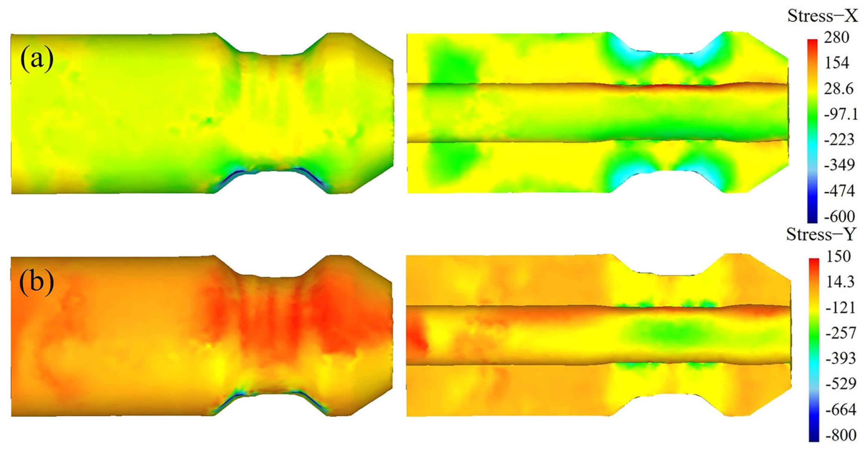
4.2.3. Analysis of the Effective Stress

Figure 18 shows the simulation results of effective stress during the hot extrusion process of the flange of the axle sleeve. As can be seen from Figure 18a,b, in the initial and middle stages of the extrusion, the maximum stress is concentrated in the local area where the workpiece contacts with the top die. As the amount of compression increases, the effective stress also significantly increases. It can be seen from Figure 18c that in the final stage of the extrusion, stress concentration occurs at the joint of the flange and the pipe (as shown in A of Figure 18c) and the part where the workpiece contacts with the bottom die (as shown in B of Figure 18c) due to large friction resistance, which hinders the metal flow. However, the effective stress in other areas is not large and evenly distributed, so the forming is safe, and the good mechanical properties can be obtained.

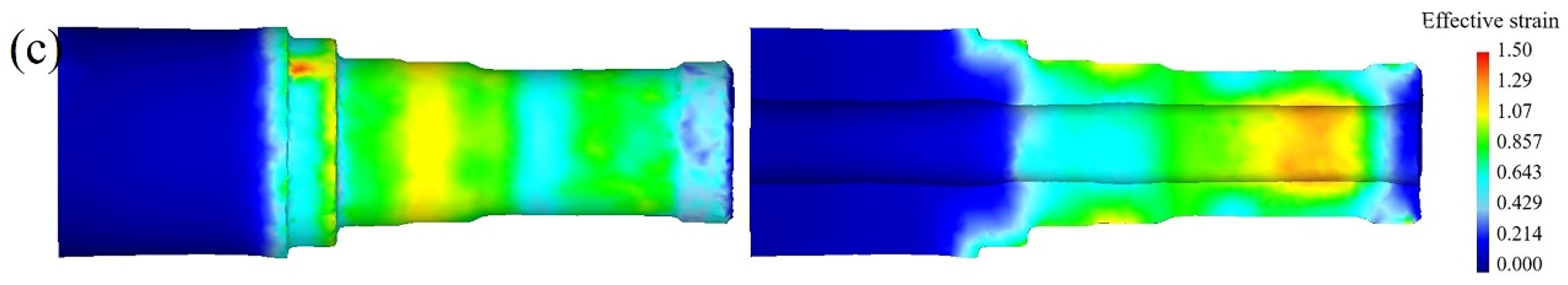
4.2.4. Analysis of the Effective Strain and Extrusion Force

Figure 19 shows the effective strain distribution in the final stage of the extrusion of the flange of the axle sleeve. It can be seen from the vertical view that the maximum strain is concentrated on the upper surface of the flange, reaching around 4. From the above analysis of the metal flow velocity, it can be seen that the metal here is subjected to small resistance and the flow velocity is large, so the deformation is relatively large. In other areas, the effective strain is below 1.8, which is very small, so defects do not easily occur, and high-quality parts can be obtained.
Figure 20 shows the extrusion force on the workpiece in the hot extrusion process. It can be seen that the extrusion force is 0 before point A, indicating that the top die and the workpiece are not yet in contact. At point A, the top die begins to contact the workpiece and the hot extrusion begins. Section AB is the stage of filling the flange cavity. Extrusion deformation occurs in the billet between the top and bottom dies. Most of the metal flows into the flange cavity. As the contact area between the workpiece and the bottom die gradually increases, the extrusion force required for deformation also gradually increases, so the load in section AB continues to rise. At point B, the flange is basically formed, only the corners of the flange have not yet been formed, and metal is needed to further fill the cavity. The metal radial flow in BC section becomes more and more difficult, so the extrusion force increases sharply at this stage, which is also consistent with the actual production situation. The hot extrusion ends at point C. The maximum extrusion force is 3084 KN, which is one order of magnitude higher than that of CWR. It can be seen that using the CWR process can effectively reduce equipment load and reduce equipment weight.

5. Experimental Verification

The CWR and hot extrusion experiments are carried out by using the parameters and conditions of FE simulation. Figure 21 shows the results of the CWR experiment. It can be seen from Figure 21a that the surface of the part obtained via CWR is well formed, the step is accurately formed, the axial and radial dimensions meet the process requirements, the inner holes are well formed, there is no eccentricity and the wall thickness is symmetrically distributed along the axial direction. The billet with an eccentric inner hole is manufactured through machining for forming the axle sleeve through CWR, and the result is shown in Figure 21b. The maximum wall thickness difference in the original billet due to the eccentric inner hole is 1.5 mm. The left side of the rolled piece is not involved in deformation, indicating the original wall thickness of the billet. The eccentricity of the inner hole on the right side that participated in deformation is significantly improved with a maximum wall thickness difference of 0.3 mm. Therefore, CWR can effectively improve the eccentricity of the inner hole of the billet.
After hot extrusion forming, the axle sleeve with good flange forming is obtained, as shown in Figure 22.

6. Conclusions

In this paper, the methods of finite element simulation and experiment are used to study the combined CWR and hot extrusion process forming axle sleeves. The forming mechanism of the axle sleeve is revealed, and the experiment is carried out to verify the feasibility of the CWR and hot extrusion combined process for producing the axle sleeve. The economical and efficient formation are realized, in which the material utilization is increased by about 10%, and the energy consumption is reduced by about 15%. The conclusions are as follows:
  • The process of forming the axle sleeve via CWR and hot extrusion is simulated using the finite element method. The change rule of stress and strain of the billet during the forming process is shown, and the forming mechanism of the axle sleeve is revealed. The workpiece can achieve diameter compression and wall thickness reduction through high compressive stress between the die and mandrel, which is beneficial to improve the quality performance of the rolled piece.
  • Through the analysis of finite element numerical simulation results combined with experimental verification, the results show the feasibility of the combined CWR and hot extrusion process for producing an axle sleeve.
  • In the process of hot extrusion, the temperature of the main deformation parts of the workpiece is within the temperature range of good forming, the metal streamline is continuous and uniform, the effective stress and effective strain are not large and evenly distributed and high-quality parts can be obtained.
  • The rolling force of CWR is one order of magnitude lower than the extrusion force of hot extrusion. The use of the CWR process can effectively reduce the load and weight of equipment.
  • CWR can effectively improve the eccentricity of the inner hole of the billet. The internal and external steps of the axle sleeve obtained through the combination of CWR and hot extrusion are formed well. The flange is well formed, and the metal streamline is continuous. The axis of the inner hole does not easily deviate, and the wall thickness is symmetrically distributed along the axis. The product quality is good, and the production efficiency is high.

Author Contributions

Conceptualization, W.S. and C.Y.; data curation, W.S.; funding acquisition, C.Y.; methodology, W.S. and C.Y.; resources, C.Y.; supervision, C.Y.; writing—original draft, W.S.; writing—review and editing, W.S. and C.Y. All authors have read and agreed to the published version of the manuscript.

Funding

This work is supported by the National Key R&D Program of China (Grant No. 2018YFB1307900) and Engineering Research Center of Part Near-Net-Shape Forming, Ministry of Education.

Data Availability Statement

The datasets and material generated and/or analyzed during the current study are available from the corresponding author on reasonable request.

Conflicts of Interest

The authors have no conflict of interest/competing interest to declare that are relevant to the content of this article.

References

  1. Hansson, S.; Jansson, T. Sensitivity analysis of a finite element model for the simulation of stainless steel tube extrusion. J. Mater. Process. Technol. 2010, 210, 1386–1396. [Google Scholar] [CrossRef]
  2. Zhou, J.K.; Xue, K.M.; Xv, Y.Q.; Li, P. Numerical simulation and experimental study on hot extrusion forming of half shaft bushing. J. Plast. Eng. 2011, 18, 15–21. [Google Scholar] [CrossRef]
  3. Xv, Y.Q.; Xue, K.M.; Zhou, J.K.; Li, P.; Qian, C.H. The influencing factors of forming force in hot extrusion process of half shaft bushing. Die. Mould. Technol. 2011, 5, 11–16. [Google Scholar] [CrossRef]
  4. Zhang, C.S.; Zhao, G.Q.; Chen, H.; Guan, Y.J.; Kou, F.J. Numerical simulation and metal flow analysis of hot extrusion process for a complex hollow aluminum profile. Int. J. Adv. Manuf. Technol. 2012, 60, 101–110. [Google Scholar] [CrossRef]
  5. Negendank, M.; Müller, S.; Reimers, W. Extrusion of Aluminum Tubes with Axially Graded Wall Thickness and Mechanical Characterization. Procedia CIRP 2014, 18, 3–8. [Google Scholar] [CrossRef] [Green Version]
  6. Gattmah, J.; Ozturk, F.; Orhan, S. Effects of Process Parameters on Hot Extrusion of Hollow Tube. Arab. J. Sci. Eng. 2017, 42, 2021–2030. [Google Scholar] [CrossRef]
  7. Li, P.; Luo, J.G.; Zhu, X.K.; Zhao, W.L.; Jin, H.; Zhou, L. Parameters optimization of precise extrusion forming process for half axle shaft tubes of heavy trucks. J. Plast. Eng. 2020, 27, 79–85. [Google Scholar] [CrossRef]
  8. Yang, C.P.; Zhang, K.S.; Hu, Z.H. Numerical simulation study on the cause of ellipse generation in two-roll cross wedge rolling the hollow parts with uniform inner diameter. Chin. J. Eng. 2012, 34, 1426–1431. [Google Scholar] [CrossRef]
  9. Yang, C.P.; Hu, Z.H. Research on the ovality of hollow shafts in cross wedge rolling with mandrel. Int. J. Adv. Manuf. Technol. 2016, 83, 67–76. [Google Scholar] [CrossRef]
  10. Ma, J.W.; Yang, C.P.; Zheng, Z.H.; Zhang, K.S.; Ma, W.Y. Influence of process parameters on the microstructural evolution of a rear axle tube during cross wedge rolling. Int. J. Miner. Metall. Mater. 2016, 23, 1302–1314. [Google Scholar] [CrossRef]
  11. Yang, C.P.; Ma, J.W.; Hu, Z.H. Analysis and design of cross wedge rolling hollow axle sleeve with mandrel. J. Mater. Process. Technol. 2016, 239, 346–358. [Google Scholar] [CrossRef]
  12. Huo, Y.M.; Lin, J.G.; Bai, Q.; Wang, B.Y.; Tang, X.F.; Ji, H.C. Prediction of microstructure and ductile damage of a high-speed railway axle steel during cross wedge rolling. J. Mater. Process. Technol. 2016, 239, 359–369. [Google Scholar] [CrossRef]
  13. Huang, X.; Wang, B.Y.; Mu, Y.H.; Shen, J.X.; Li, J.L.; Zhou, J. Investigation on the effect of mandrels on hollow shafts in cross-wedge rolling. Int. J. Adv. Manuf. Technol. 2019, 102, 443–455. [Google Scholar] [CrossRef]
  14. Huang, X.; Wang, B.Y.; Lin, J.G.; Zhu, C.B. Effect of mandrel diameter on non-circularity of hollow shafts in cross wedge rolling. Procedia Eng. 2017, 207, 2376–2381. [Google Scholar] [CrossRef]
  15. Shen, J.X.; Wang, B.Y.; Yang, C.P.; Zhou, J.; Cao, X.Q. Theoretical study and prediction of the inner hole reduction and critical mandrel diameter in cross wedge rolling of hollow shaft. J. Mater. Process. Technol. 2021, 294, 117140. [Google Scholar] [CrossRef]
  16. Lin, L.F.; Wang, B.Y.; Shen, J.X.; Liu, T. Producing hollow shafts in a new horizontal mill by novel flat-knifing cross-wedge rolling with single guide. Int. J. Adv. Manuf. Technol. 2021, 118, 2685–2700. [Google Scholar] [CrossRef]
  17. Feng, P.N.; Yang, C.P.; Wang, B.Y.; Li, J.L.; Liu, R.E. Microstructure and mechanical properties of TC4 titanium alloy hollow shaft formed by cross wedge rolling. Arch. Civ. Mech. Eng. 2021, 21, 129. [Google Scholar] [CrossRef]
  18. Feng, P.N.; Yang, C.P.; Wang, B.Y.; Li, J.L.; Shen, J.X.; Yang, X.M. Formability and microstructure of TC4 titanium alloy hollow shafts formed by cross-wedge rolling with a mandrel. Int. J. Adv. Manuf. Technol. 2021, 114, 365–377. [Google Scholar] [CrossRef]
  19. Feng, P.N.; Wang, B.Y.; Yang, C.P.; Ju, Z.D.; Zhang, H.B. The Formability, Microstructure, and Mechanical Properties of Powder-Sintered TC4 Alloy Hollow Shafts Formed by Cross-Wedge Rolling. J. Mater. Eng. Perform. 2022, 31, 8989–9000. [Google Scholar] [CrossRef]
  20. Shi, J.A.; Liu, J.P.; Wang, B.Y.; Shen, J.X. Numerical and experimental research on warm cross wedge rolling of hollow shafts with corrugated surface. Int. J. Adv. Manuf. Technol. 2022, 122, 243–262. [Google Scholar] [CrossRef]
Figure 1. Part drawing and forming process route of the axle sleeve: (a) part drawing; (b) billet; (c) punching; (d) CWR; (e) hot extrusion.
Metals 13 01017 g001
Figure 2. (a) Finite element model of CWR; (b) flattened diagram of the CWR tool.
Metals 13 01017 g002
Figure 3. Finite element model of hot extrusion.
Metals 13 01017 g003
Figure 4. (a) FE simulation results of CWR of the axle sleeve; (b) profile of FE simulation results.
Metals 13 01017 g004
Figure 5. Grid of the rolled part before and after forming: (a) before forming; (b) after forming.
Metals 13 01017 g005
Figure 6. Stress distribution on the cross section in the knifing zone: (a) transverse stress; (b) radial stress; (c) axial stress; (d) effective stress.
Metals 13 01017 g006
Figure 7. Stress distribution on the longitudinal section in the knifing zone: (a) transverse stress; (b) radial stress; (c) axial stress; (d) effective stress.
Metals 13 01017 g007
Figure 8. Stress distribution on the cross section in the stretching zone: (a) transverse stress; (b) radial stress; (c) axial stress; (d) effective stress.
Metals 13 01017 g008
Figure 9. Stress distribution on the longitudinal section in the stretching zone: (a) transverse stress; (b) radial stress; (c) axial stress; (d) effective stress.
Metals 13 01017 g009aMetals 13 01017 g009b
Figure 10. Strain distribution on the cross section in the stretching zone: (a) transverse strain; (b) radial strain; (c) axial strain.
Metals 13 01017 g010aMetals 13 01017 g010b
Figure 11. Strain distribution on the longitudinal section in the stretching zone: (a) transverse strain; (b) radial strain; (c) axial strain.
Metals 13 01017 g011
Figure 12. Effective strain distribution on the cross section in the process of CWR of the axle sleeve: (a) knifing zone; (b) stretching zone; (c) sizing zone.
Metals 13 01017 g012
Figure 13. Effective strain distribution on the longitudinal section in the process of CWR of the axle sleeve: (a) knifing zone; (b) stretching zone; (c) sizing zone.
Metals 13 01017 g013aMetals 13 01017 g013b
Figure 14. Axial displacement of the axle sleeve formed via CWR.
Metals 13 01017 g014
Figure 15. The change in rolling force.
Metals 13 01017 g015
Figure 16. The change in workpiece temperature in the hot extrusion process: (a) initial stage of the extrusion; (b) middle stage of the extrusion; (c) final stage of the extrusion.
Metals 13 01017 g016
Figure 17. Simulation results of metal flow velocity during the hot extrusion process: (a) initial stage of the extrusion; (b) middle stage of the extrusion; (c) final stage of the extrusion.
Metals 13 01017 g017
Figure 18. Simulation results of effective stress during the hot extrusion process: (a) initial stage of the extrusion; (b) middle stage of the extrusion; (c) final stage of the extrusion.
Metals 13 01017 g018
Figure 19. Effective strain distribution in the final stage of the extrusion: (a) vertical view; (b) main view.
Metals 13 01017 g019
Figure 20. The change in extrusion force.
Metals 13 01017 g020
Figure 21. Results of CWR experiment: (a) outline drawing and section drawing of the rolled piece; (b) inner hole deviation correction results of CWR.
Metals 13 01017 g021
Figure 22. Results of hot extrusion experiment.
Metals 13 01017 g022
Table 1. FE simulation parameters of CWR.
FE Parameter (Unit)Value
Speed of roller (rpm)10
Initial temperature of workpiece (°C)1100
Initial temperature of tool (°C)20
Environment reference temperature (°C)20
Heat convection coefficient with air (N/s/mm/°C)0.02
Contact heat transfer coefficient (N/s/mm/°C)11
Emissivity0.8
Friction factor (workpiece and die)1
Friction factor (workpiece and guide plate)0.2
Initial element number of workpiece1.1 × 105
Table 2. FE simulation parameters of hot extrusion.
FE Parameter (Unit)Value
Speed of the top die (mm/s)30
Initial temperature of workpiece (°C)1050
Initial temperature of the top die (°C)300
Initial temperature of the bottom die (°C)400
Environment reference temperature (°C)20
Heat convection coefficient with air (N/s/mm/°C)0.02
Contact heat transfer coefficient (N/s/mm/°C)5
Emissivity0.8
Disclaimer/Publisher’s Note: The statements, opinions and data contained in all publications are solely those of the individual author(s) and contributor(s) and not of MDPI and/or the editor(s). MDPI and/or the editor(s) disclaim responsibility for any injury to people or property resulting from any ideas, methods, instructions or products referred to in the content.

