Article

Reorientation Mechanisms of Graphene Coated Copper {001} Surfaces

1
State Key Laboratory of Metal Matrix Composites, School of Materials Science and Engineering, Shanghai Jiao Tong University, Shanghai 200240, China
2
Department of Mechanical and Materials Engineering, University of Nebraska-Lincoln, Lincoln, NE 68588, USA
*
Authors to whom correspondence should be addressed.
Metals 2023, 13(5), 910; https://doi.org/10.3390/met13050910
Submission received: 14 April 2023 / Revised: 4 May 2023 / Accepted: 6 May 2023 / Published: 8 May 2023

Abstract

:
Engineering the surface orientation of face-centered cubic (fcc) metals to the close-packed {111} plane can significantly enhance their oxidation resistance. However, owing to the synergetic effect of surface energy density ( γ ˙ ) and strain energy density ( ω ), such close-packed surface orientation can currently only be achieved by atomic-level thin film epitaxy or monocrystallization of polycrystalline metals. In this study, we characterized the microstructures of pure copper (Cu) foil and two types of graphene-coated Cu (Gr/Cu) foils and observed a 12~14 nm thick reconstructed surface layer with the {111} orientation in the high-temperature deposited Gr/{001} Cu surface. Combining the statistical results with thermodynamic analysis, we proposed a surface melting-solidification mechanism for the reconstruction of the Cu surface from {001} orientation to {111} orientation. This process is dominated by Gr/Cu interfacial energy and is particularly promoted by high-temperature surface melting. We also validated such a mechanism by examining Cu surfaces coated by h-BN (hexagonal boron nitride) and amorphous carbon. Our findings suggest a possible strategy to enhance the surface properties of fcc metals via engineering surface crystallography.

1. Introduction

Crystal orientation is one of the critical factors that dominates the surface corrosion and oxidation resistance of metals due to the varying surface energies and atomic structures associated with different crystal orientations [1,2,3,4,5]. Generally, close-packed crystallographic planes have been known to exhibit the lowest surface energy and thereby shows high corrosion and oxidation resistance [6,7]. In contrast, high-indexed crystallographic planes generally manifest high chemical reactivity due to their large surface energy levels [8,9]. Since metallic materials are generally polycrystalline, improving the surface corrosion and oxidation resistance is critical for metals that are generally exposed to high temperature or corrosive environment, such as Cu-based thermal management materials and Cu interconnections in micro-electromechanical systems (MEMS) [10,11].
Nanoscale non-active surface coatings can be an effective barrier to physically isolate the metal matrix from its surrounding media, thereby improving the surface properties of metals [6]. Therefore, extensive research has been focused on developing the surface coating technologies, including vapor deposition, spray coating, and plasma electrolytic oxidation, to introduce coating materials on metal surfaces [12,13,14,15,16]. Besides, the effectiveness of corrosion/oxidation protection of surface coatings is found to be related to their chemical composition, thickness, and adhesion strength with metal matrix [17,18,19]. As a result, many efforts have also been made toward the developing of advanced coating materials. Recently, Wei et al. reported that the surface orientation of metal matrix may significantly affect the stability of surface coatings and demonstrated the effectiveness of the close-packed metal surface in retarding the degradation of the surface coating layer [20]. Therefore, engineering surface orientations to close-packed planes can not only enhance the intrinsic corrosion and oxidation resistance of metal surfaces but may also be important for improving the anti-corrosion properties of surface coatings. For instance, Kim et al. show that epitaxial Cu film with the {111} orientation exhibits nearly permanent resistance to oxidation [7]. Liu et al. found that the magnetron-sputtered {111}-textured Cu/Ni films yield greater surface hardness than their {001}-textured counterparts [21]. Moreover, Wei et al. also reported that introducing the {111} surface steps on metal surfaces can significantly enhance the stability of passive films and consequently enhance the corrosion resistance of stainless steel [20]. However, fcc metals that are processed by traditional strategies (such as annealing, deformation-based surface treatment, and surface alloying) mostly exhibit {001} orientation with huge surface island and step structures, owing to the synergetic effect of strain energy and surface energy minimization [22,23,24,25]. Metal surfaces with close-packed orientation can currently only be realized by atomic-level thin film epitaxy on single crystal substrates or {111} monocrystallization of polycrystalline metals [7,26,27,28], which are rather expensive and difficult to scale up for industrial applications. Therefore, a novel strategy that enables us to effectively tune the surface of commercial materials to their close-packed orientation is desired.
For surface grains of metallic materials, the free energy density (G) of the grain plays an important role in determining the crystal orientation. Generally, G can be approximately expressed as G = ω + γ ˙ , where ω is the strain energy density that is determined by biaxial modulus and γ ˙ is the surface energy density [24,29,30]. As these two parameters are both anisotropic with crystallographic orientations [31,32,33], tailoring the surface orientations may be achieved by tuning ω or γ ˙ . For example, the close-packed {111} orientation in face-centered cubic (fcc) metals exhibits the largest biaxial modulus and thereby yields the largest ω [34]. As a result, when ω dominating G, fcc metals may form other orientations to reduce G although the {111} orientation exhibits the lowest γ ˙ . Based on this theory, Li et al. altered Cu surface orientation to high index orientations, such as {510} and {430}, by tailoring thermal stresses during annealing [24]. In such a case, it can be expected that the {111} orientation will be predominant if γ ˙ related energy density dominates G. However, the γ ˙ dominated {111} orientation currently only can be realized in nano sized or free-standing fcc metals [28,35]. Bulk metal surfaces generally exhibit {001} orientation and are accompanied by complex low surface energy facets (surface islands or steps) after heat treatment, due to the synergetic effect of ω and γ ˙ (Figure 1a) [12,13,14,15]. Since ω is an intrinsic parameter that is determined by the biaxial modulus, tailoring γ ˙ might be a feasible strategy to achieve closed-packed surface orientation.
Coating two-dimensional materials (such as graphene (Gr) and hexagonal boron nitride (h-BN)) on metal surfaces may change γ ˙ of surface grains [36,37]. Extensive work has shown the formation of step bunching on graphene (Gr)-covered Cu surfaces after annealing [38,39,40]. The corresponding mechanisms were ascribed to the minimization of surface energy and elastic bending energy of Gr. Especially, minimizing Gr bending strain energy can promote surface diffusion/dislocation activities during heat treatment and thereby smooths the metal surface (Figure 1a). However, surface reorientation does not happen in such cases. One possible reason could be the insufficient driving force associated with the minimization of interface energy. Previous studies demonstrated that surface melting is a common phenomenon during the thermal treatment of metal. At a specific temperature, a surface melting layer with a certain thickness will form on the metal surface [41,42]. Therefore, we speculated that surface reorientation can be realized by modifying the surface energy density of the surface melting layer via a two-dimensional surface coating (Figure 1b).
Gr deposition, which is generally accomplished at 1273 K, may provide the opportunity to achieve surface melting [38]. Besides, the non-intermixing nature between Gr and Cu can also enable us to discuss the influence of γ ˙ on surface orientation. Therefore, the Gr/Cu system is an ideal model to verify the hypothesis on tailoring surface orientation by changing the thermodynamic condition of the metal surface. In this work, we fabricated various Cu foils, including pure {001} Cu and Gr-coated {001} Cu that is processed by Gr deposition or Gr transferring. By systematically characterizing their surface and cross-sectional microstructures with atomic force microscopy (AFM) and transmission electron microscopy (TEM), we confirmed the formation of the {111}-reconstructed layer on Gr coated {001} Cu surface and found that surface melting and Gr coverage are two important factors to determine the formation of such layer. Besides, combining the statistical result on reconstructed layer thickness with thermodynamic analysis, we show that there is a correlation between surface melting phenomena and the thickness of the {111} reconstructed layer. Correspondingly, a Gr/Cu interface energy dominated melting-solidification mechanism was proposed to realize the surface reconstruction. Our results can not only enrich our understanding on tailoring surface crystallography but also may provide a novel strategy to design Cu-based materials with enhanced surface oxidation and corrosion resistance.

2. Experiments

2.1. Materials

The {001}-orientated and annealed Cu foil was obtained by annealing an industrial cold-rolled polycrystalline Cu foil (25 μm in thickness) at 1273 K under H2 protection for 30 min. The industrially cold-rolled Cu foils were acquired from KJMTI Co. Ltd. (Hefei, China). Gr was synthesized on the annealed Cu foil at 1273 K in a homemade low-pressure deposition system with a quartz furnace tube of 1.6 m in length and 100 mm in diameter. Gr deposition was done using gas fluxes of CH4 (~6 standard cubic centimeter per minute, s.c.c.m.) and H2 (~200 s.c.c.m.) [23] and followed by rapid cooling in the circulating water cooling system, resulting in the deposited Gr/Cu foils. The annealed-transferred Gr/Cu foils were fabricated by transferring free-standing Gr onto the annealed {001} Cu foil, followed by a 1273 K heat treatment. Free-standing Gr was obtained by etching the Cu substrate of deposited Gr/Cu samples in a ferric chloride (FeCl3) solution. Prior to etching the Cu substrate, a 0.5 wt.% polymethyl methacrylate (PMMA) anisole solution was spin coated on the deposited Gr/Cu to protect the Gr. After the Cu substrate was dissolved, the PPMA/Gr film was cleaned with deionized water and then transferred onto the annealed {001} Cu substrate. The PPMA was finally removed by acetone. In addition, amorphous carbon can be obtained by tuning the gas flux ratio of CH4 and H2. The h-BN is deposited on the same {001}-Cu foil using ammonia borane as a precursor (NH3–BH3, 99.999% purity, Alfa Aesar Co., Ltd. (Haverhill, MA, USA)) at 1273 K under the gas flux of argon (Ar) (200 s.c.c.m.) and H2 (50 s.c.c.m.). The deposition process is also accomplished in a homemade low-pressure deposition system equipped with a quartz furnace tube of 1.6 m in length and 100 mm in diameter.

2.2. Materials Characterization

Raman spectroscopy (Bruker Optics Senterra R200-L, Brucker, Billerica, MA, USA) equipped with a 532 nm Ar+ laser source was carried out to characterize the Gr, h-BN, and amorphous carbon. All the Raman spectroscopy experiments are conducted at ambient temperature. For Gr, there are three characteristic peaks located at 1350 cm−1, 1580 cm−1, and 2700 cm−1 Raman shift [43]. Generally, the three peaks are known as the D, G, and 2D peaks. The presence of the D peak suggests the Gr is defective. In contrast, the intensity of the G peak increases almost linearly with Gr layer numbers, and the 2D peak shifts to a high Raman shift with increasing Gr layer numbers. Therefore, the relative intensity of these three peaks is the basis for identifying Gr layer numbers and crystallinity. For example, IG/I2D can be used to identify the Gr layer number, while ID/IG is used to clarify the crystallinity of Gr [43]. According to the reference, the high intensity of the D peak should be the characteristic of amorphous carbon [23]. As for h-BN, only one characteristic peak will appear at ~1365 cm−1 Raman shift [44]. It is worth noting that all the Raman spectra are acquired on a Si substrate. The h-BN/Si and amorphous carbon/Si composites are obtained by transferring free-standing h-BN and amorphous carbon onto Si substrates using the same transferring method for preparing the transferred Gr/Cu. Besides, the surface roughness of various Gr/Cu foils is analyzed using an Oxford Instrument MFP-3D atomic force microscopy (AFM, Oxford Instrument, Abingdon, UK). Prior to cross-sectional analysis, a Cu cap layer of 100 nm was sputtered on the various Gr/Cu foils with a deposition power of 50 W in a magnetron sputter from Kurt J. Lesker Company (Jefferson Hills, PA, USA). The Cu cap layer can minimize the plastic deformation of the surface and the ion beam radiation effect on the surface morphologies during the focus ion beam (FIB). Cross-sectional samples were prepared by the FIB lift-out technique inside a Tescan GAIA 3 dual beam scanning electron microscopy (SEM, Tescan, Brno, The Czech Republic) with a resolution of ~2.5 nm. The prepared samples exhibit 10 μm in length and ~100 nm in thickness. The cross-sectional samples were then analyzed using JEOL JEM 2100F transmission electron microscopy (TEM, JEOL Ltd., Tokyo, Japan) that operated at 200 kV.

2.3. Molecular Dynamics Simulation

We utilized the interatomic potential of Cu that obtained by empirical embedded-atom-method to conduct the molecular dynamics (MD) simulations [45], which enables us to determine the energy and atomic structure of the {111}/{100} Cu interface. Firstly, we calculated the generalized stacking fault energy (SFE) (γ-surface) of the coherent interface using the equilibrium lattice parameter (a = 3.615 Å) and constructed a coherent bi-crystal model with the upper crystal having an orientation of x-[01 1 ¯ ], y-[111], and z-[2 1 ¯ 1 ¯ ], and the lower crystal having an orientation of x-[011], y-[100], and z-[01 1 ¯ ]. Coherency strains εxx are zero, while εzz = 7.7% and −6.7% are applied in the upper and lower crystals, respectively, corresponding to the interface crystallography. The bi-crystal model has dimensions of 2.0 nm × 34.7 nm × 1.9 nm, with periodic boundary conditions along the x- and z-directions and a fixed boundary condition along the y-direction by semi-fixing the thickness of the surface atoms with a thickness of approximately 1 nm. We then rigidly shifted the upper crystal by an in-plane vector μ = (ux, 0, uz) with respect to the lower crystal, and the rigidly shifted configurations were relaxed by energy minimization, allowing atom relaxation only along the y-direction at a fixed shift vector μ. By subtracting the cohesive energy and the strain-induced elastic energy in the strained crystals from the total potential energy (E[μ]), we obtained the formation energy of the coherent interfaces as a function of the shift vector (γ[μ]). Secondly, we obtained the structure of the semi-coherent interface. The semi-coherent bi-crystal model had the same orientations for the two half-crystals as in the coherent interface model. The upper crystal had 20 and 60 periodicities along the x- and z-directions, respectively, while the lower crystal had 20 and 104 periodicities along the x- and z-directions, respectively, resulting in coherency strains of 0% and 0.07%, which were negligible compared to the coherent interface model. The semi-coherent model had dimensions of 5.1 nm × 16.9 nm × 26.5 nm, with a total of 184,800 atoms. Periodic boundary conditions were used along the x- and z-directions, while a fixed boundary condition was used along the y-direction by semi-fixing the thickness of the surface atoms to approximately 1 nm. The bi-crystal model was fully relaxed by energy minimization, allowing atom relaxation in three dimensions. The relaxed interface structure was obtained by plotting atoms on the nearest {111} and {100} planes in the interface region.

3. Results

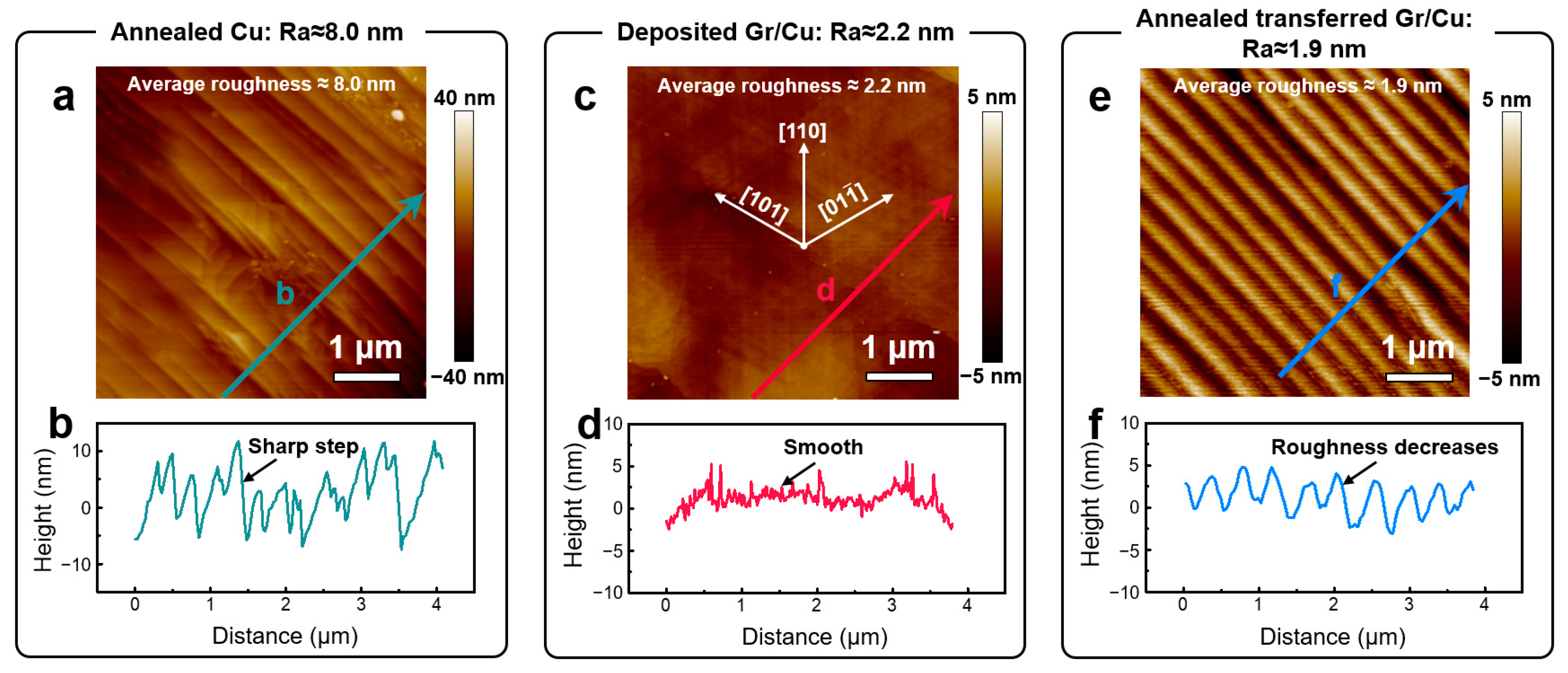
Figure 2 compares the morphology differences of the fabricated Cu surfaces. There are profuse parallel steps on the annealed Cu surface, with the average surface roughness (Ra) at ~8.0 nm (Figure 2a). Besides, the corresponding line scan profile also indicate the sharpness of these steps (Figure 2b). In contrast, severe variation in surface roughness appears in the deposited Gr/Cu. As shown in Figure 2c,d, the Ra is 2.2 nm without obvious evidence of sharp surface steps, indicating the possibility of forming surface reconstruction. Moreover, the surface morphology of the deposited Gr/Cu surface manifests some parallel traces following symmetric crystallographic directions with an angle of 60°. We anticipate the formation of a six-fold symmetry {111} Cu surface, where these parallel traces following the [101], [110], and [01 1 ¯ ] directions. Similarly, the annealed-transferred Gr/Cu foil in Figure 2e,f exhibits a comparable decrease in surface roughness with Ra ~1.9 nm. However, no obvious symmetric surface traces are found, indicated the possibility of the absence of {111} surface reconstruction. Since it is obvious that the {111} reconstructed features only appeared on deposited Gr/Cu, these results also suggest that Gr deposition is critical in triggering the surface reconstruction. However, a more detailed cross-sectional analysis is still needed to understand the nature of the Cu surface reconstruction.
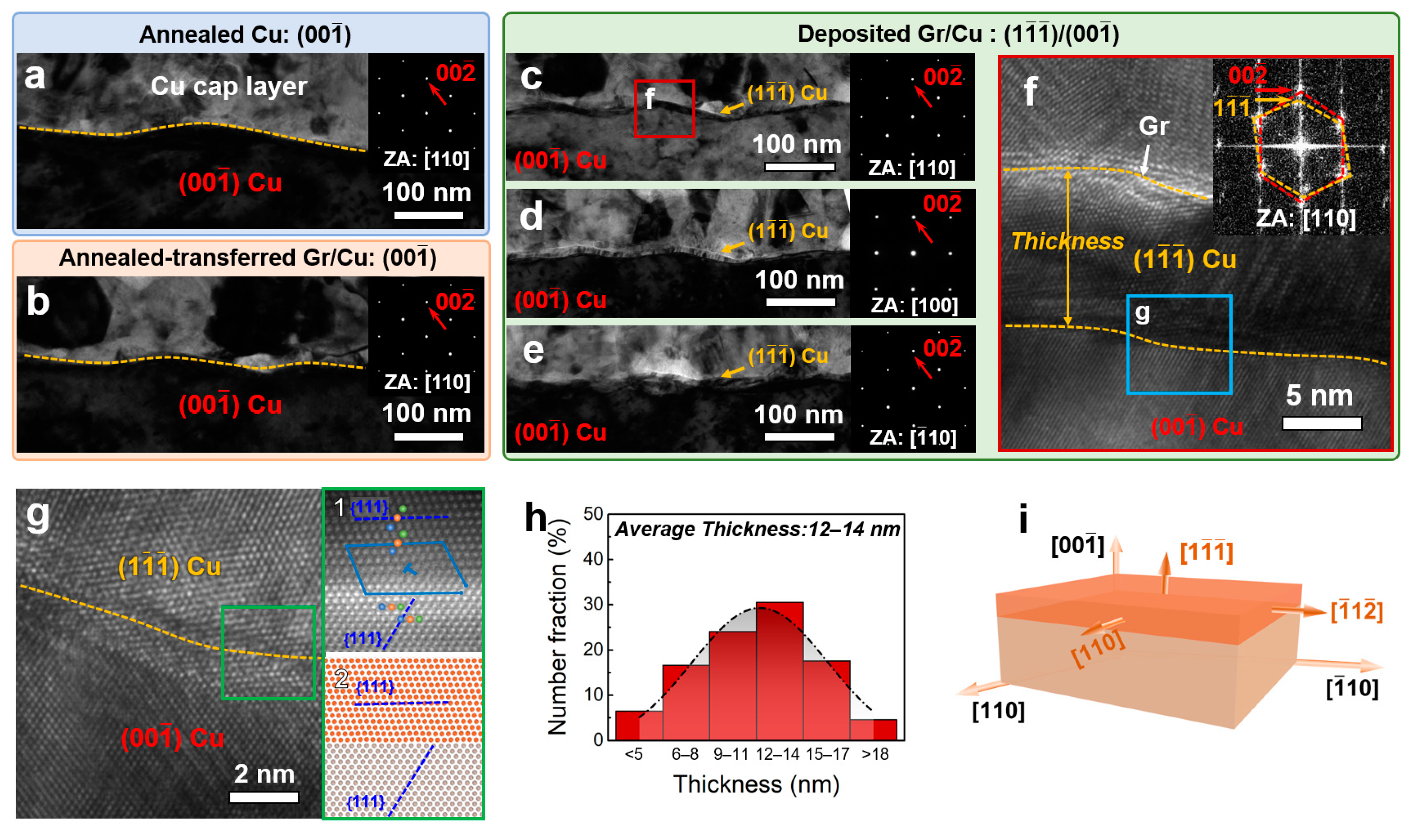
We then examined the cross-sectional morphology of TEM samples prepared by the SEM-FIB technique. Figure 3a &b present the cross-sectional TEM images of pure Cu and transferred Gr/Cu foils. Both the image contrast and select area electron diffraction (SAED) patterns suggesting the {001} orientation in the surface region. These results confirmed the absence of surface reconstruction on these two samples, which is consisted with Figure 2a,b,e,f. In contrast, a dark surface layer appears on the deposited Gr/Cu surface (Figure 3c). However, the SAED pattern in the inset shows no additional diffraction spots due to the finite thickness. By tilting the sample inside the TEM, we further confirmed the existence of the surface layer from the other two viewing directions ([001] and [ 1 ¯ 10]), as marked by yellow arrows in Figure 3d,e. High-resolution TEM (HRTEM) and corresponding fast Fourier transformation (FFT) analysis reveal that the {001} to {111} crystallographic transition in the surface region and is accompanied by the formation of (1 1 ¯ 1 ¯ )||(001) interface (Figure 3f). In addition, the {111} surface layer shares the same [110] zone axis with the {001} Cu matrix. The atomic structure at the enlarged interface area not only confirmed the {001} to {111} crystallographic transition but also revealed the misfit dislocation at the (1 1 ¯ 1 ¯ )||(001) interface (Figure 3g). Moreover, statistical analysis of the {111} layer thickness showed an average thickness of 12–14 nm (Figure 3h). Therefore, the {111} reconstructed layer with the [110]layer||[110]Cu, [ 1 ¯ 1 2 ¯ ]layer||[ 1 ¯ 10]Cu, and (1 1 ¯ 1 ¯ )layer||(00 1 ¯ )Cu crystallographic orientation can be determined (Figure 3i).

4. Discussion

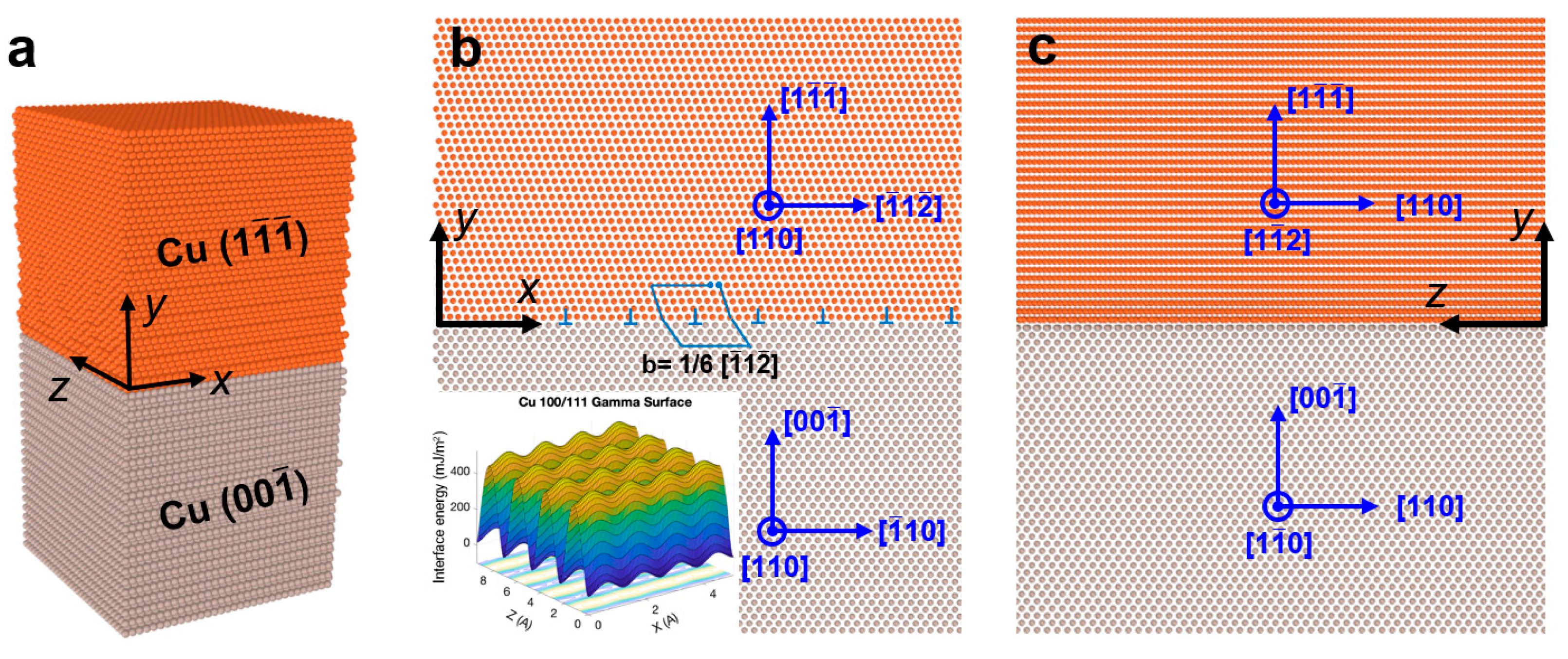
Generally, a surface layer with a determined thickness and crystallography are the common features of thin film epitaxy [46]. Meanwhile, interface misfit dislocation will form to relax the elastic strain energy caused by the crystallographic discontinuity between different layers [47]. For the {111} surface layer with the crystallographic orientation in Figure 3i, the molecular dynamic (MD) simulations show that a periodic misfit dislocation pattern with Burgers vector of 1 6 [ 1 ¯ 1 2 ¯ ] will appear to accommodate the uniaxial lattice misfit between the [1 1 ¯ 2] and [ 1 ¯ 10] directions (Figure 4). This theoretical result is similar to the Burgers circuit at the interface area in Figure 3g, demonstrating a closure failure of 1 2 [ 1 ¯ 10 ]. It is worth noting that the difference in the Burgers vector may be attributed to the combination of the two 1 6 < 1 ¯ 1 2 ¯ > partial dislocations during sample preparation or strain relaxation [48]. Therefore, the existence of misfit dislocation confirms the formation of the {111} reconstructed layer but then raises important questions on why and how this {111} reconstructed layer forms.
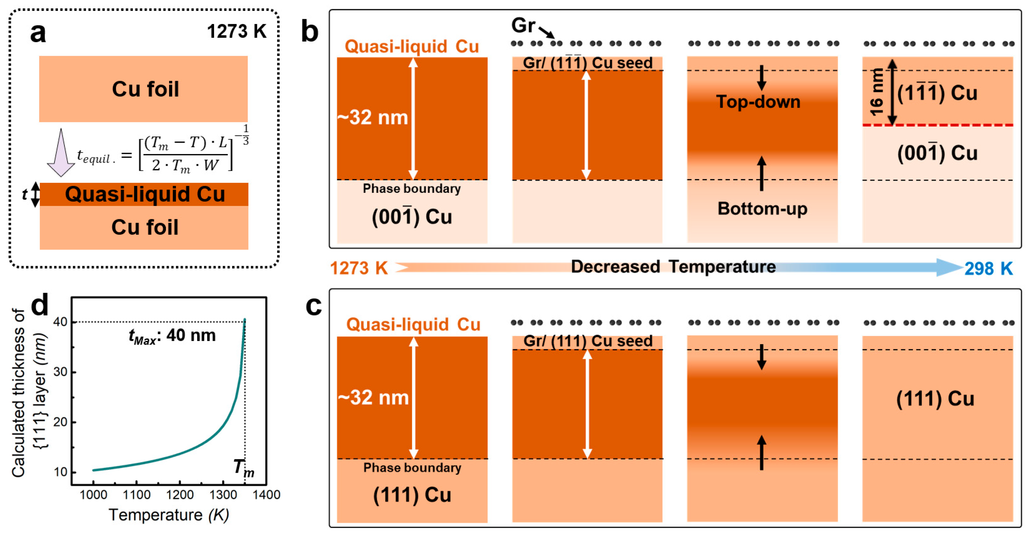
Both previous experimental and theoretical results have demonstrated that metal surfaces will become slightly melted (quasi-liquid) (Figure 5a) to reduce the surface free energy, even when the temperatures are below their bulk-melting point ( T m ) [49,50]:
γ s > γ s l + γ l v ,
where γ s refers to the initial surface free energy of Cu; γ s l and γ l v are the free energies after surface melting, including solid-liquid and liquid-vapor interface energies. At a specific temperature that approaches the melting point, a surface melting layer with a certain thickness will form on the surface. In the consideration that a melted layer will exhibit repulsive interaction between two opposite surfaces (two sides of the melt layer in our study) towards decreasing their surface energy by forming a spherical shape. Meanwhile, undercooling energies associated with the melting layer also contribute to the free energy. Therefore, the total free energy of the melted layer can be written as [50]:
F l = γ s l + γ l v + W l 2 + L · ( 1 T T m ) · l ,
where W is the Hamaker constant of Cu and L is the latent heat of melted Cu per unit volume [51,52]. The third term of Equation (2) describes the repulsive interaction that tends to decrease the Fl, and the fourth term is the undercooling energies; they are both functions of melting layer thickness. As a result, an equilibrium state can be achieved when F l is minimal, i.e., d F l d l = 0 . Correspondingly, the equilibrium thickness of the surface melting layer can be calculated as:
l e q u i l . = ( T m T ) · L 2 · T m · W 1 3 ,
At 1273 K, the t e q u i l . of Cu is calculated as ~32 nm, which is twice of the statistical {111} layer thickness, suggesting the surface melting may correlate to the formation of surface reconstruction. In pure Cu, the melted layer will transform back to the same orientation as the un-melted counterpart after cooling down, owing to the synergetic effect of both ω and γ ˙ (Figure 3a). Once Gr is introduced on top of the Cu surface, the Gr/Cu interface forms, and the free energy density changes to the following:
G = ω + γ ˙ s + γ ˙ i ,
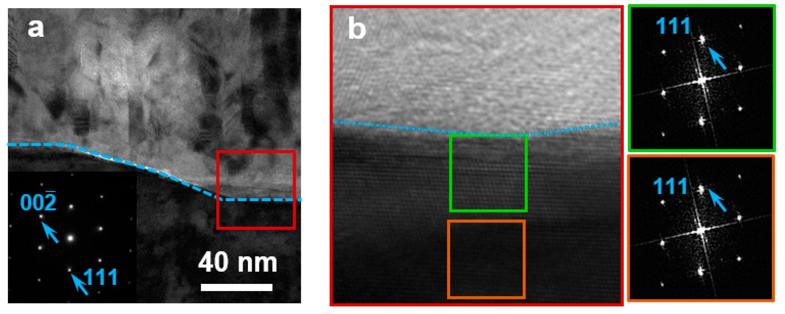
where γ ˙ s is the surface energy density of Gr and γ ˙ i represents the interface energy density associated with the Gr/Cu interface. Compared with other interface orientations, the Gr/{111} Cu interface exhibits the lowest interface energy of ~1100 mJ/m2 at high temperatures [24], indicating the formation of Gr/{111} interface can decrease G and hence is energetically favorable. If the Gr/{111} Cu interface can act as a seed layer for subsequent solidification, it can be expected that a {111} layer will be formed due to the template effect of the Gr/{111} Cu interface [46,53]. Therefore, combing the misfit dislocation, thickness, and crystallographic features of the {111} layer on Gr coated {001} Cu surface, we speculated that the formation of the {111} reconstruction layer is likely related to an epitaxial growth-like process. In such case, it is reasonable to assume that the melted layer will solidify from both the upper Gr/{1 1 ¯ 1 ¯ } Cu interface and bottom solid-liquid phase boundary simultaneously (Figure 5b), following the atomic stacking sequences of the Gr/{111} Cu interface and bottom {001} Cu matrix, respectively. Besides, the continuous nucleation and growth of Gr grains may also lead to the formation of numerous Gr/{111} Cu seeds on the surface of the melted layer. Consequently, upper and bottom solidified Cu will meet each other with the decreasing of temperature. As a result, a {111} layer forms on the {001} Cu surface (Figure 5b,c). Therefore, a {111}||{001} interface is observed in the {001} oriented Cu, while continuous {111} orientation is still maintained in the {111} Cu (Figure 6). It is worth noting that, although the {111} Cu and {001} Cu may have different nucleating rates, here we may approximately estimate the same value due to the finite thickness and high surface cooling rate with up to ~400 K/s. Based on this approximation, the thickness of the {111} layer can be estimated as half of the equilibrium thickness of the melted layer:
t { 111 } = 1 2 · ( T m T ) · L 2 · T m · W 1 3 ,
At 1273 K, the thickness of {111} layer is calculated as 16 nm, very close to the measured experimentally, 12–14 nm. Using Equation (5), the {111} layer thickness as a function of processing temperature is plotted in Figure 5d. It is shown that the thickness of the {111} layer only depends on the thermodynamic condition, i.e., the temperature. Please note that the processing temperature should be below the melting point to maintain the structural stability of the substrate. Therefore, the maximum thickness of the {111} layer on Cu is ~40 nm (Figure 5d). As a result, it can be concluded that the formation of the {111} layer is a spontaneous process during Gr deposition. In comparison, the absence of the {111} reconstruction on the annealed-transferred Gr/{001} Cu may be attributed to the stabilization effect of Gr on Cu surface melting. For example, Ananthakrishnan et al. demonstrated that the pre-existence of Gr can significantly delay the Cu surface melting by MD simulation [54]. Therefore, surface melting also determined the formation of {111} reconstructed layer.
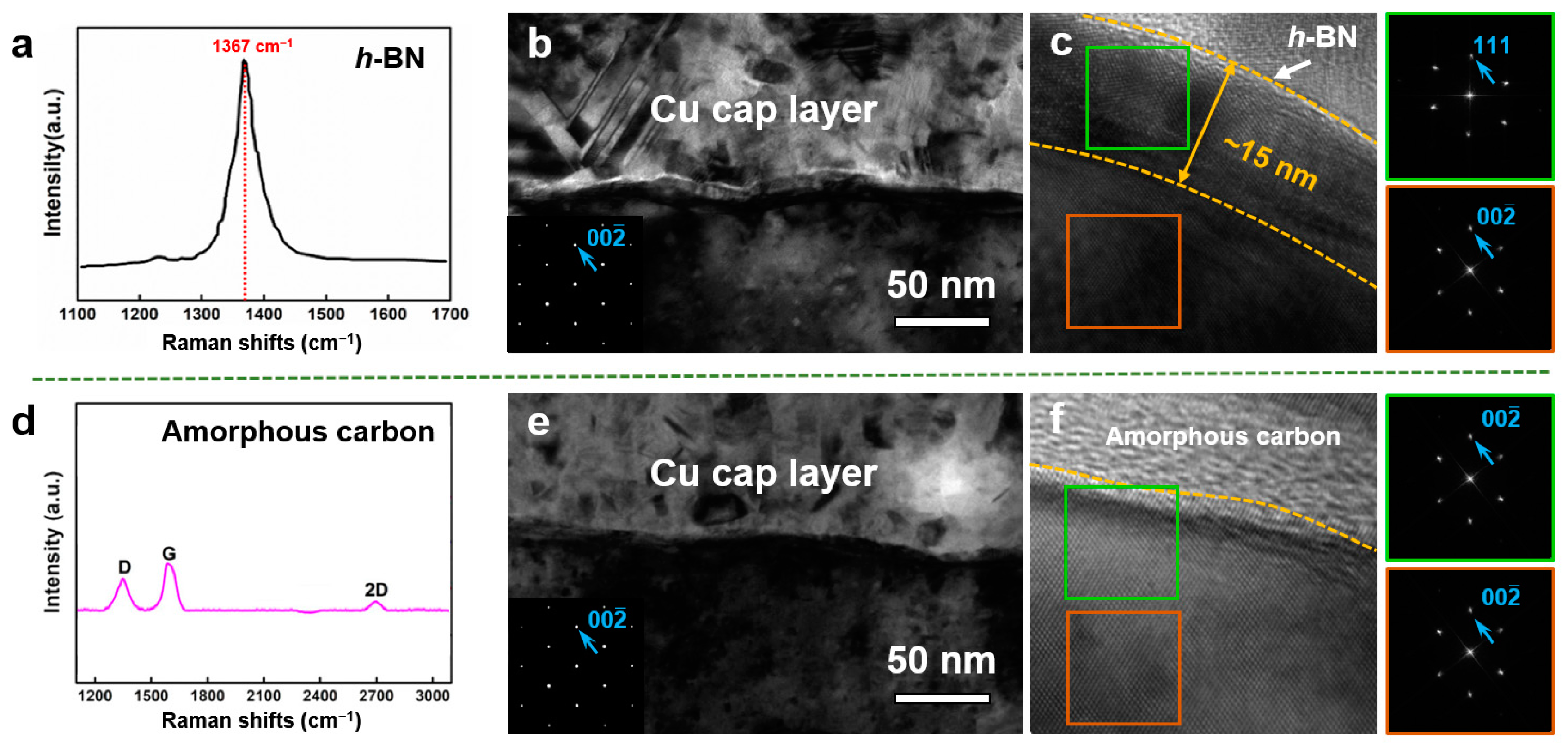
Considering that Gr is one of the typical model materials used to modify the metal surface energy, theoretically, we can control the type of surface coating materials to realize the {111} reconstructed layer on other fcc metals. To examine our hypothesis and validate the melting-solidification mechanism, we substituted Gr with h-BN and amorphous carbon and conducted similar deposition experiments at 1273 K. The synthesis of h-BN and amorphous carbon is first verified by Raman spectra, where an obvious Raman peak appears at 1367 cm−1 in the prepared h-BN sample while a prominent D peak at ~1350 cm−1 occurs in the deposited amorphous carbon. The cross-sectional TEM analysis shows that h-BN can induce a comparable {111} reconstructed layer with a thickness of ~15 nm, while surface reconstruction is not observed on amorphous carbon/Cu foil (Figure 7). This may be attributed to the fact that amorphous carbon has almost no influence on Cu surface energy [55]. In contrast, h-BN exhibits a similar crystal structure with Gr, thereby changing the surface energy and triggering the {111} reconstruction. This result suggests the importance of the crystallinity of coating materials in triggering surface reconstruction. The proposed melting-solidification mechanism may thus open an avenue for tailoring the formation of the {111} reconstruction layer in a variety of fcc metals (such as Cu, Ni, and Pt) via proper high-temperature treatment and selection of surface coating materials.

5. Conclusions

In this work, using AFM, TEM characterizations, MD simulations, and statistical analysis on various Gr/Cu foils, the following conclusions can be drawn:
(1)
The study confirmed the formation of a 12~14 nm thick {111} reconstructed layer on the high-temperature deposited Gr/{001} Cu surface.
(2)
By correlating the surface melting with {111} reconstructed layer, a melting-solidification mechanism was proposed to understand the formation mechanism of the surface reconstruction.
(3)
The proposed mechanism was then verified by coating h-BN and amorphous carbon on Cu surfaces.
(4)
The melting-solidification mechanism provides two important criteria that ensure the formation of close-packed {111} surface orientation in fcc metals: (i) an appropriate processing temperature that provides sufficient surface melting thickness, and (ii) a crystalline surface coated layer (including Gr and h-BN) that can modify the interfacial energy density.
Our findings may enrich our understanding of crystallographic engineering for enhancing the surface properties of metals and alloys.

Author Contributions

J.S. performed the TEM experiments under the guidance of Y.L.; S.Y., Q.L. and J.S. analyzed the data; J.S., J.N. and Z.Y. performed the AFM experiments; K.Y. synthesized the Gr/Cu sample; G.L. conducted the MD simulations; J.S., Y.L. and J.W. wrote and modified the manuscript; Y.L. and J.W. conceived the main idea and designed all the experiments. All authors have read and agreed to the published version of the manuscript.

Funding

Y.L. acknowledges the financial support of the National Natural Science Foundation of China (No. 52171144).

Institutional Review Board Statement

Not applicable.

Informed Consent Statement

Not applicable.

Data Availability Statement

The data in this study are available upon request.

Conflicts of Interest

The authors declare no conflict of interest.

References

  1. Hori, Y.; Takahashi, I.; Koga, O.; Hoshi, N. Selective Formation of C2 Compounds from Electrochemical Reduction of CO2 at a Series of Copper Single Crystal Electrodes. J. Phys. Chem. B 2001, 106, 15–17. [Google Scholar] [CrossRef]
  2. Quan, Z.; Wang, Y.; Fang, J. High-Index Faceted Noble Metal Nanocrystals. Acc. Chem. Res. 2012, 46, 191–202. [Google Scholar] [CrossRef] [PubMed]
  3. Xu, X.; Zhang, Z.; Dong, J.; Yi, D.; Niu, J.; Wu, M.; Lin, L.; Yin, R.; Li, M.; Zhou, J.; et al. Ultrafast epitaxial growth of metre-sized single-crystal graphene on industrial Cu foil. Sci. Bull. 2017, 62, 1074–1080. [Google Scholar] [CrossRef] [PubMed]
  4. Vitos, L.; Ruban, A.; Skriver, H.; Kollár, J. The surface energy of metals. Surf. Sci. 1998, 411, 186–202. [Google Scholar] [CrossRef]
  5. Tran, R.; Xu, Z.; Radhakrishnan, B.; Winston, D.; Sun, W.; Persson, K.A.; Ong, S.P. Surface energies of elemental crystals. Sci. Data 2016, 3, 160080. [Google Scholar] [CrossRef]
  6. Maurice, V.; Marcus, P. Progress in corrosion science at atomic and nanometric scales. Prog. Mater. Sci. 2018, 95, 132–171. [Google Scholar] [CrossRef]
  7. Kim, S.; Kim, Y.; Lamichhane, B.; Kim, Y.; Lee, Y.; Cho, C.; Cheon, M.; Kim, J.; Jeong, H.; Ha, T.; et al. Flat-surface-assisted and self-regulated oxidation resistance of Cu(111). Nature 2022, 603, 434–438. [Google Scholar] [CrossRef]
  8. Hahn, C.; Hatsukade, T.; Kim, Y.-G.; Vailionis, A.; Baricuatro, J.H.; Higgins, D.C.; Nitopi, S.A.; Soriaga, M.P.; Jaramillo, T.F. Engineering Cu surfaces for the electrocatalytic conversion of CO2: Controlling selectivity toward oxygenates and hydrocarbons. Proc. Natl. Acad. Sci. USA 2017, 114, 5918–5923. [Google Scholar] [CrossRef]
  9. Huang, K.; Crooks, R.M. Enhanced electrocatalytic activity of Cu-modified, high-index single Pt NPs for formic acid oxidation. Chem. Sci. 2022, 13, 12479–12490. [Google Scholar] [CrossRef]
  10. Mayumi, S.; Murozono, I.; Nanatsue, H.; Ueda, S. Corrosion-Induced Contact Failures in Double-Level Al-Si-Cu Metallization. J. Electrochem. Soc. 1990, 137, 1861. [Google Scholar] [CrossRef]
  11. Zuo, Y.; Robador, A.; Wickham, M.; Mannan, S.H. Unraveling the complex oxidation effect in sintered Cu nanoparticle interconnects during high temperature aging. Corros. Sci. 2022, 209, 110713. [Google Scholar] [CrossRef]
  12. Pezzato, L.; Brunelli, K.; Diodati, S.; Pigato, M.; Bonesso, M.; Dabalà, M. Microstructural and Corrosion Properties of Hydroxyapatite Containing PEO Coating Produced on AZ31 Mg Alloy. Materials 2021, 14, 1531. [Google Scholar] [CrossRef] [PubMed]
  13. Hwang, C.; Shinde, K.; Oh, J.; Lee, S.; Chung, C.; Park, J. Microstructures and high temperature oxidation behaviors of AlMo0.5NbTa0.5TiZr high entropy alloys coated by silicon pack cementation. Corros. Sci. 2023, 219, 111203. [Google Scholar] [CrossRef]
  14. Miranda-Pérez, A.F.; Rodríguez-Vargas, B.R.; Calliari, I.; Pezzato, L. Corrosion Resistance of GMAW Duplex Stainless Steels Welds. Materials 2023, 16, 1847. [Google Scholar] [CrossRef]
  15. Wang, X.-M.; Zhang, F.-Q. Effects of soft sparking on micro/nano structure and bioactive components of microarc oxidation coatings on selective laser melted Ti6Al4V alloy. Surf. Coat. Technol. 2023, 462, 129478. [Google Scholar] [CrossRef]
  16. Zhang, X.; Cui, X.; Jin, G.; Dong, Y.; Wang, Z.; Qi, Y. Microstructure evolution and performance enhancement of NbTaTiV-(Cr, Zr, W) single-phase refractory high-entropy alloy coatings: Role of additional elements. J. Alloys Compd. 2023, 951, 169918. [Google Scholar] [CrossRef]
  17. Liu, Y.; Yao, Z.; Zhang, P.; Xu, Z.; Lin, S.; He, M.; Lu, S.; Wu, X. Tailoring high-temperature oxidation resistance of FeCrMnVSi high entropy alloy coatings via building Si-rich dendrite microstructure. Appl. Surf. Sci. 2022, 606, 154862. [Google Scholar] [CrossRef]
  18. Wang, W.; Zhang, G.; Wang, C.; Wang, T.; Zhang, Y.; Xin, T. Construction of Cr coatings with different columnar structure on Zircaloy-4 alloys to optimize the high-temperature steam oxidation behavior for accident tolerant fuel claddings. J. Alloys Compd. 2023, 946, 169385. [Google Scholar] [CrossRef]
  19. Yang, J.; Fang, K.; Xu, K.; Shen, X.; Xu, X. Effect of zinc or copper doping on corrosion resistance and anti-oxidative stress of strontium-based micro-arc oxidation coatings on titanium. Appl. Surf. Sci. 2023, 626, 157229. [Google Scholar] [CrossRef]
  20. Wei, X.X.; Zhang, B.; Wu, B.; Wang, Y.J.; Tian, X.H.; Yang, L.X.; Oguzie, E.E.; Ma, X.L. Enhanced corrosion resistance by engineering crystallography on metals. Nat. Commun. 2022, 13, 1–13. [Google Scholar] [CrossRef]
  21. Liu, Y.; Bufford, D.; Wang, H.; Sun, C.; Zhang, X. Mechanical properties of highly textured Cu/Ni multilayers. Acta Mater. 2011, 59, 1924–1933. [Google Scholar] [CrossRef]
  22. Che, J.G.; Chan, C.T.; Jian, W.-E.; Leung, T.C. Surface atomic structures, surface energies, and equilibrium crystal shape of molybdenum. Phys. Rev. B 1998, 57, 1875–1880. [Google Scholar] [CrossRef]
  23. Yang, K.; Ma, Y.; Zhang, Z.; Zhu, J.; Sun, Z.; Chen, J.; Zhao, H.; Song, J.; Li, Q.; Chen, N.; et al. Anisotropic thermal conductivity and associated heat transport mechanism in roll-to-roll graphene reinforced copper matrix composites. Acta Mater. 2020, 197, 342–354. [Google Scholar] [CrossRef]
  24. Li, Y.; Sun, L.; Chang, Z.; Liu, H.; Wang, Y.; Liang, Y.; Chen, B.; Ding, Q.; Zhao, Z.; Wang, R.; et al. Large Single-Crystal Cu Foils with High-Index Facets by Strain-Engineered Anomalous Grain Growth. Adv. Mater. 2020, 32, e2002034. [Google Scholar] [CrossRef]
  25. Zhang, W. Evolution of crystal morphologies to equilibrium by surface diffusion with anisotropic surface free energy in three dimensions. J. Cryst. Growth 2006, 297, 169–179. [Google Scholar] [CrossRef]
  26. Deng, B.; Pang, Z.; Chen, S.; Li, X.; Meng, C.; Li, J.; Liu, M.; Wu, J.; Qi, Y.; Dang, W.; et al. Wrinkle-Free Single-Crystal Graphene Wafer Grown on Strain-Engineered Substrates. ACS Nano 2017, 11, 12337–12345. [Google Scholar] [CrossRef] [PubMed]
  27. Wu, M.; Zhang, Z.; Xu, X.; Zhang, Z.; Duan, Y.; Dong, J.; Qiao, R.; You, S.; Wang, L.; Qi, J.; et al. Seeded growth of large single-crystal copper foils with high-index facets. Nature 2020, 581, 406–410. [Google Scholar] [CrossRef] [PubMed]
  28. Jin, S.; Huang, M.; Kwon, Y.; Zhang, L.; Li, B.-W.; Oh, S.; Dong, J.; Luo, D.; Biswal, M.; Cunning, B.V.; et al. Colossal grain growth yields single-crystal metal foils by contact-free annealing. Science 2018, 362, 1021–1025. [Google Scholar] [CrossRef] [PubMed]
  29. Thompson, C.V.; Carel, R. Texture development in polycrystalline thin films. Mater. Sci. Eng. B 1995, 32, 211–219. [Google Scholar] [CrossRef]
  30. Sonnweber-Ribic, P.; Gruber, P.; Dehm, G.; Arzt, E. Texture transition in Cu thin films: Electron backscatter diffraction vs. X-ray diffraction. Acta Mater. 2006, 54, 3863–3870. [Google Scholar] [CrossRef]
  31. Thompson, C.V.; Carel, R. Stress and grain growth in thin films. J. Mech. Phys. Solids 1996, 44, 657–673. [Google Scholar] [CrossRef]
  32. Rhead, G.; McLean, M. Variation of surface energy with crystallographic orientation in silver. Acta Met. 1964, 12, 401–407. [Google Scholar] [CrossRef]
  33. Vlassak, J.J.; Nix, W. Measuring the elastic properties of anisotropic materials by means of indentation experiments. J. Mech. Phys. Solids 1994, 42, 1223–1245. [Google Scholar] [CrossRef]
  34. Yang, K.; Liu, G.; Ma, H.; Song, J.; Li, Q.; Chen, N.; Wang, Y.; Chen, D.; Liu, Y.; Fan, T. Formation of misfit dislocation arrays and helium nanochannels near copper surface assisted by high-temperature graphene deposition. Acta Mater. 2022, 237, 118134. [Google Scholar] [CrossRef]
  35. Liang, W.; Zhou, M.; Ke, F. Shape Memory Effect in Cu Nanowires. Nano Lett. 2005, 5, 2039–2043. [Google Scholar] [CrossRef] [PubMed]
  36. Yang, K.; Li, Q.; Zhang, Q.; Liu, G.; Wang, J.; Yang, Y.; Guo, C.; Ni, J.; Song, J.; Zhang, J.; et al. Synergistically enhanced interface stability by graphene assisted copper surface reconstruction. Acta Mater. 2022, 226, 117638. [Google Scholar] [CrossRef]
  37. Takahashi, J.; Ueyama, T.; Kamei, K.; Kato, H.; Homma, Y. Experimental and theoretical studies on the surface morphology variation of a Ni substrate by graphene growth. J. Appl. Phys. 2021, 129, 024302. [Google Scholar] [CrossRef]
  38. Wang, Z.-J.; Weinberg, G.; Zhang, Q.; Lunkenbein, T.; Klein-Hoffmann, A.; Kurnatowska, M.; Plodinec, M.; Li, Q.; Chi, L.; Schloegl, R.; et al. Direct Observation of Graphene Growth and Associated Copper Substrate Dynamics by in Situ Scanning Electron Microscopy. ACS Nano 2015, 9, 1506–1519. [Google Scholar] [CrossRef] [PubMed]
  39. Deng, B.; Wu, J.; Zhang, S.; Qi, Y.; Zheng, L.; Yang, H.; Tang, J.; Tong, L.; Zhang, J.; Liu, Z.; et al. Anisotropic Strain Relaxation of Graphene by Corrugation on Copper Crystal Surfaces. Small 2018, 14, e1800725. [Google Scholar] [CrossRef]
  40. Yi, D.; Luo, D.; Wang, Z.-J.; Dong, J.; Zhang, X.; Willinger, M.-G.; Ruoff, R.S.; Ding, F. What Drives Metal-Surface Step Bunching in Graphene Chemical Vapor Deposition? Phys. Rev. Lett. 2018, 120, 246101. [Google Scholar] [CrossRef]
  41. Bienfait, M.; Gay, J.-M. Surface Melting and Diffusion. In Phase Transitions in Surface Films 2; Taub, H., Torzo, G., Lauter, H., Fain, S., Eds.; Springer: Boston, MA, USA, 1991; pp. 307–325. [Google Scholar]
  42. Levi, A. On Surface Melting. In Phase Transitions in Surface Films 2; Taub, H., Torzo, G., Lauter, H., Fain, S., Eds.; Springer: Boston, MA, USA, 1991; pp. 327–338. [Google Scholar]
  43. Ferrari, A.C.; Meyer, J.C.; Scardaci, V.; Casiraghi, C.; Lazzeri, M.; Mauri, F.; Piscanec, S.; Jiang, D.; Novoselov, K.S.; Roth, S.; et al. Raman spectrum of graphene and graphene layers. Phys. Rev. Lett. 2006, 97, 187401. [Google Scholar] [CrossRef]
  44. Arenal, R.; Ferrari, A.C.; Reich, S.; Wirtz, L.; Mevellec, J.-Y.; Lefrant, S.; Rubio, A.; Loiseau, A. Raman Spectroscopy of Single-Wall Boron Nitride Nanotubes. Nano Lett. 2006, 6, 1812–1816. [Google Scholar] [CrossRef] [PubMed]
  45. Foiles, S.M.; Baskes, M.I.; Daw, M.S. Embedded-atom-method functions for the fcc metals Cu, Ag, Au, Ni, Pd, Pt, and their alloys. Phys. Rev. B 1986, 33, 7983–7991. [Google Scholar] [CrossRef] [PubMed]
  46. Liu, Y.; Chen, Y.; Yu, K.; Wang, H.; Chen, J.; Zhang, X. Stacking fault and partial dislocation dominated strengthening mechanisms in highly textured Cu/Co multilayers. Int. J. Plast. 2013, 49, 152–163. [Google Scholar] [CrossRef]
  47. Shao, S.; Wang, J. Relaxation, Structure, and Properties of Semicoherent Interfaces. JOM 2015, 68, 242–252. [Google Scholar] [CrossRef]
  48. Shao, S.; Akasheh, F.; Wang, J.; Liu, Y. Alternative misfit dislocations pattern in semi-coherent FCC {100} interfaces. Acta Mater. 2018, 144, 177–186. [Google Scholar] [CrossRef]
  49. Frenken, J.W.M.; van der Veen, J.F. Observation of Surface Melting. Phys. Rev. Lett. 1985, 54, 134–137. [Google Scholar] [CrossRef]
  50. van der Veen, J. Surface-Induced Melting of Solids. In Phase Transitions in Surface Films 2; Taub, H., Torzo, G., Lauter, H., Fain, S., Eds.; Springer: Boston, MA, USA, 1991; pp. 289–305. [Google Scholar]
  51. Eichenlaub, S.; Chan, C.; Beaudoin, S.P. Hamaker Constants in Integrated Circuit Metalization. J. Colloid Interface Sci. 2002, 248, 389–397. [Google Scholar] [CrossRef]
  52. Ferreira, I.L. On the Heat Capacity of Pure Elements and Phases. Mater. Res. 2021, 24, e20200529. [Google Scholar] [CrossRef]
  53. Liu, Y.; Song, J.; Liu, G.; Chen, J.; Wang, C.; Wang, H.; Wang, J.; Zhang, X. High Strength and Low Coercivity of Cobalt with Three-Dimensional Nanoscale Stacking Faults. Nano Lett. 2021, 21, 6480–6486. [Google Scholar] [CrossRef]
  54. Ananthakrishnan, G.; Surana, M.; Poss, M.; Yaacoub, J.J.; Zhang, K.; Admal, N.; Pochet, P.; Tawfick, S.; Johnson, H.T. Graphene-mediated stabilization of surface facets on metal substrates. J. Appl. Phys. 2021, 130, 165302. [Google Scholar] [CrossRef]
  55. Yang, K.; Tang, P.; Zhang, Q.; Ma, H.; Liu, E.; Li, M.; Zhang, X.; Li, J.; Liu, Y.; Fan, T.; et al. Enhanced defect annihilation capability of the graphene/copper interface: An In Situ study. Scr. Mater. 2021, 203, 114001. [Google Scholar] [CrossRef]
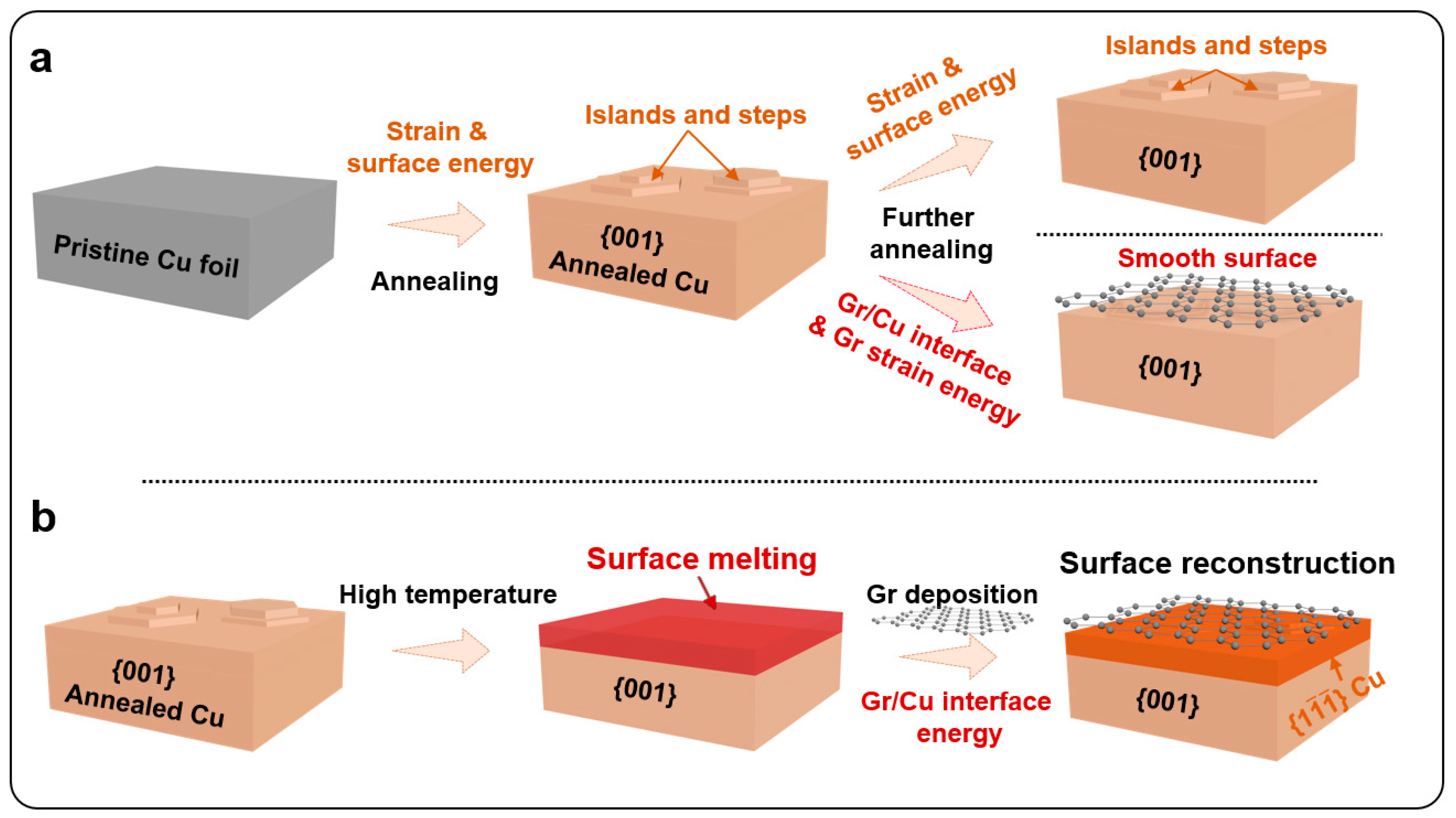
Figure 1. Schematics of Cu surface modification. (a) {001} Cu is the preferred orientation after annealing, owing to the lowest strain energy density. Besides, {001}-oriented Cu always exhibits surface islands or steps that are composed of low-energy facets to reduce the free energy. Besides, introducing Gr can modify the surface energy and introduce Gr strain energy, but the surface orientation still maintains {001}. (b) Based on surface melting and Gr deposition, we hypothesize that Gr deposition may provide an opportunity to tailor surface orientation from {001} to {111}.
Metals 13 00910 g001
Figure 2. Surface morphology of various Cu foils revealed by atomic force microscopy (AFM). (a) The AFM image shows the average surface roughness of annealed Cu foil is around 8.0 nm. (b) Line profile along the light green arrow in (a). (c) In comparison, the surface roughness of high-temperature-treated Gr/Cu foil decreases to 2.2 nm. Besides, three sets of surface traces with an angle of 60° appeared. (d) Line profile along the red arrow. (e,f) Surface roughness also decreases on the annealed–transferred Gr/Cu foil, but no obvious {111} features are found.
Metals 13 00910 g002
Figure 3. Cross-sectional analysis of various Cu foils revealed by transmission electron microscopy (TEM). (a,b) TEM images and selected area electron diffraction (SAED) patterns indicate the {001} surface orientation of annealed Cu and transferred Gr/Cu foil. (c) A dark surface layer appeared on high-temperature treated Gr/Cu foil. No additional diffraction spots are observed in SAED. (d) Additional TEM images were taken from the [100] and (e) [ 1 ¯ 10] zone axes. (f) High-resolution TEM (HRTEM) image taken from the red rectangular, suggesting the surface orientation is {111} rather than {001}. (g) HRTEM analysis shows the surface layer exhibits the atomic stacking sequence of fcc crystal (g1) and is consistent with the theoretical crystal structure (g2). In addition, interface misfit dislocation with a Burgers vector of 1/2 [ 1 ¯ 1 0 ] is identified with the Burgers circuit. (h) Statistical result of the thickness of the {111} reconstruction layer, showing the average thickness is 12–14 nm. (i) A three-dimensional schematic is obtained by combining the TEM results with crystallographic analysis.
Metals 13 00910 g003
Figure 4. The atomic structure of the {111} || {001} interface was revealed by molecular dynamic (MD) simulation. (a) The relaxed incoherent {111}upper/{001}lower bi-crystal model. (b,c) Interface dislocations and orientation analysis from two orthogonal directions. The model exhibits the [110]upper||[110]lower, [ 1 ¯ 1 2 ¯ ]upper||[ 1 ¯ 10]lower, and (1 1 ¯ 1 ¯ )upper||(00 1 ¯ )lower orientations. When viewing from the [110]upper||[110]lower direction, misfit dislocations with Burgers vector of 1/6 [ 1 ¯ 1 2 ¯ ] are observed, owing to the uniaxial lattice misfit between the [ 1 ¯ 1 2 ¯ ]upper and [ 1 ¯ 10]lower. The inset in (b) is the gamma surface of the {111}||{001} interface.
Metals 13 00910 g004
Figure 5. Formation mechanism of the {111} layer on Gr coated {001} Cu. (a) The Cu surface suffered a surface melting phenomenon at temperatures below the melting point. (b) A surface melting-solidifying mechanism was proposed that enables the formation of the {111} layer. (c) In comparison, the {111} Cu still maintained the initial orientation. (d) The {111} layer thickness as a function of processing temperature, indicating the layer thickness only depends on processing temperature.
Metals 13 00910 g005
Figure 6. Cross-sectional analysis of the high-temperature treated Gr/{111}Cu. (a) Low magnified TEM image; (b) HRTEM image and corresponding FFT analysis taken form red frame in (a). The results show that the surface still maintained a continuous {111} orientation in spite of a slight distortion.
Metals 13 00910 g006
Figure 7. Cross-sectional analysis of h-BN/Cu and amorphous carbon/Cu foils. (a) Raman spectra indicating the fabrication of h-BN (b) TEM images show the formation of the surface layer. (c) HRTEM and FFT analysis confirmed the transformation of the surface from {001} to {111}. Besides, the thickness of the {1 1 ¯ 1 ¯ } layer is ~15 nm, which is consistent with the Gr/Cu sample and our proposed surface melting–solidification mechanism. (df) In comparison, surface reconstruction is not observed on amorphous carbon/Cu foil.
Metals 13 00910 g007
Disclaimer/Publisher’s Note: The statements, opinions and data contained in all publications are solely those of the individual author(s) and contributor(s) and not of MDPI and/or the editor(s). MDPI and/or the editor(s) disclaim responsibility for any injury to people or property resulting from any ideas, methods, instructions or products referred to in the content.