Article

Weldability of Additive Manufactured Stainless Steel in Resistance Spot Welding

1
Department of Mechanical Convergence Engineering, Hanyang University, 222 Wangsimni-ro, Seongdong-gu, Seoul 04763, Republic of Korea
2
Advanced Joining & Additive Manufacturing R&D Department, Korea Institute of Industrial Technology, 156 Gaetbeol-ro, Yeonsu-gu, Incheon 21999, Republic of Korea
3
Department of Convergence Manufacturing System Engineering, University of Science and Technology (UST), 217 Gajeong-ro, Yuseong-gu, Daejeon 34113, Republic of Korea
*
Authors to whom correspondence should be addressed.
Metals 2023, 13(5), 837; https://doi.org/10.3390/met13050837
Submission received: 9 March 2023 / Revised: 13 April 2023 / Accepted: 18 April 2023 / Published: 24 April 2023
(This article belongs to the Special Issue New Trends on Spot Welding in Metals and Alloys)

Abstract

:
The manufacture of complicated automobile components that are joined by resistance spot welding requires considerable cost and time. The use of additive manufacturing technology to manufacture automobile components helps reduce the overall time consumption and yields high accuracy. In this study, the weldability of conventional (C) 316L stainless steel and additive manufactured (AM) 316L stainless steel was evaluated and analyzed. After deriving the lobe diagram for both the materials, the monitoring data, nugget diameter, tensile shear strength, and hardness were analyzed. The findings of the study have opened up a massive potential for use in resistance spot welding technology for additive manufactured materials’ industries in the forthcoming years. When AM 316L stainless steel was welded in the constant current control mode, a nugget diameter of up to 4.7 mm, which is below the international standard, could be secured. Through the constant power control mode, however, the nugget diameter could be improved to a sufficient level of 5.8 mm.

1. Introduction

Austenitic stainless steels are extensively used in several industry verticals owing to affordable cost, excellent corrosion, and good fatigue resistance [1]. The stainless steel grade 316L, namely conventional (C) 316 L stainless steel, which is among the most widely adopted materials, contain only the austenite phase owing to high ductility, significant strength, excellent corrosion resistance, and good weldability [2,3]. However, the traditional approach to preparing and characterizing this steel is expensive, and the fabrication of parts with accurate and complicated structures is time consuming [1]. Therefore, to overcome the aforementioned drawbacks, there has been a recent surge in the research on metal-based additive manufacturing (AM) technologies, especially in the automobile industry. The increasing research may be further attributed to the ability to manufacture complex structures within a short time and with high precision [4].
Selective laser melting (SLM) has attracted attention in recent years [2]. This method can produce full dense components and evade time-consuming postprocessing cycles [4]. The 316L stainless steel is among the most common metals for SLM mainly owing to good consolidation [5]. However, there are dimensional limitations for parts manufactured using SLM. The welding technology may help address this issue because it allows seamless production of large parts [6].
Several welding methods have been used in applications such as gas tungsten arc welding (GTAW), shielded metal arc welding, and resistance spot welding (RSW) [3,4,6,7,8]. RSW has been widely adopted in manufacturing industries for joining metal sheets owing to factors such as repeatability and ease of use [3,9]. RSW is a fusion welding method wherein two or more metal sheets derive pressure and heat that are required for welding from an electric current.
There have been several research studies aiming at developing ways to evaluate and improve the weldability of conventional (C) stainless steel, which is a commercially used material, as well as AM stainless steel, which is manufactured using the AM technique. Huysmans et al. evaluated welding characteristics for the GTAW of AM 316L stainless steel [9]. Järvinen, J.P. et al. compared the welding characteristics of AM stainless steel and C stainless steel through tungsten inert gas welding [8]. In addition to these studies, there has been considerable research on laser welding. Ruizhi Zhang and Ville-Pekka Matilainen et al. evaluated the laser weldability of AM 316L stainless steel [10,11]. Casalino, G. et al. extensively studied the hybrid laser weldability of SLM stainless steel [12]. Yang, J. et al. evaluated the laser weldability of SLM 304 stainless steel [13]. Laitinen et al. compared the laser weldability characteristics of powder bed fusion 316L stainless steel and C 316L stainless steel [14]. A few studies have analyzed the impact of RSW process parameters on the weldability of austenitic stainless steels. Danial Kianersi et al. [3] optimized welding parameters, such as welding current and time, for the RSW of the C stainless steel sheets grade AlSI 316L. Khuenkaew, T. et al. [15] examined the weldability and mechanical properties of 316L/425 stainless steels joined by resistance spot welding with respect to variable weld current and times. Kocabekir, B. [16] examined the weldment characteristics of the joint C 316L stainless steel using resistance spot welding. Although several studies have been actively conducted on resistance spot welding for C stainless steel, in addition to laser welding and arc welding for AM stainless steel, the resistance spot welding for AM stainless steel has not been sufficiently analyzed.
In this study, the resistance spot welding characteristics of AM 316L stainless steel and C 316L stainless steel were compared through mechanical and structural perspectives based on cross-section analysis, tensile tests, and welding signal analysis. In addition, for AM 316L stainless steel with low welding quality, the potential of the CPC mode to improve the weld quality was explored.

2. Experimental Procedure

2.1. Experimental Material

The 316L stainless steel cold worked by rolling and powder bed fusion 316L stainless steel, referred to as C 316L stainless steel and AM 316L stainless steel, respectively, were used as the base metals. The thickness of the steel was 1.5 mm. The AM 316L stainless steel was manufactured using a Concept Laser M2 machine with a laser power of 210 W, laser scan speed of 700 mm/s, hatching spacing of 150 μm, and a layer thickness of 30 μm. The porosity in AM 316L stainless steel was averaged by taking at least ten representative locations of transverse and longitudinal cross sections in the same magnification using optical microscopy (OM), showing the average porosity fraction under these parameters was 0.117%. The chemical compositions of C 316L stainless steel and AM 316L stainless steel were measured using an inductively coupled plasma optical emission spectrometer (ICP–OES; Optima 8300, Perkin Elmer, Norwalk, CT, USA), as shown in Table 1. For each material, experiments were performed by overlapping the same material. The size of the specimens was 125 × 45, corresponding to the ISO standard [17].

2.2. Experimental Setup

The equipment used in the resistance spot welding experiment is shown in Figure 1. The experiments were carried out on a medium-frequency direct-current (MFDC) resistance spot welding machine, which has a control frequency of 1.0 kHz and a maximum current of 20.0 kA. Furthermore, two modes, constant current control (CCC) welding and constant power control (CPC) welding are operated in the same welding machine. The welding gun used in the experiments can operate to a maximum load of 6.0 kN. Figure 1 shows the equipment for welding and the schematic diagrams of systems that are used to measure welding signals such as welding current and voltage. The welding current was measured using the Rogowski coil, and the welding voltage was measured through the voltage probe, as shown in Figure 1. The range of welding current that can be measured is 0–15,000 A. The welding voltage (V) was measured using the NI9229 (NATIONAL INSTRUMENTS Corp., Austin, TX, USA) voltage measurement module by National Instruments. A welding voltage between −60 and 60 V can be measured. The inverter control frequency of the MFDC inverter RSW machine used in the experiment was 1.0 kHz, and the pulse-width modulation (PWM) control was performed once every half cycle (0.5 ms). Because the welding signal was measured at a sampling rate of 50 kHz, the current and voltage were calculated using 25 data per 0.5 ms from raw data. As welding was performed in the CCC and CPC modes, the average value algorithm was used to calculate welding current and voltage according to 25 current and voltage data points per 0.5 ms [18]. The dynamic resistance (R), welding power (P), and the total heat input (Q) were calculated using Equations (1)–(3):
R t = V t / I t
P t = V t × I t
Q Total = P t · d t
where I(t) is the RMS value of the welding current, V(t) is the RMS value of the welding voltage, R(t) is the resistance, P(t) is the power, and Q is the heat [19]. The electrode displacement was measured at the same sampling rate as the electrical signal and calculated at the same frequency period to synchronize with the current and voltage signals [20].

2.3. Cross-Section Analysis

Cross-sectional analysis was performed to measure the nugget diameter and observe the cross-sectional shape. The test piece was manufactured as shown in Figure 2. The central part of the prepared test piece was cut to observe the central part of the nugget.

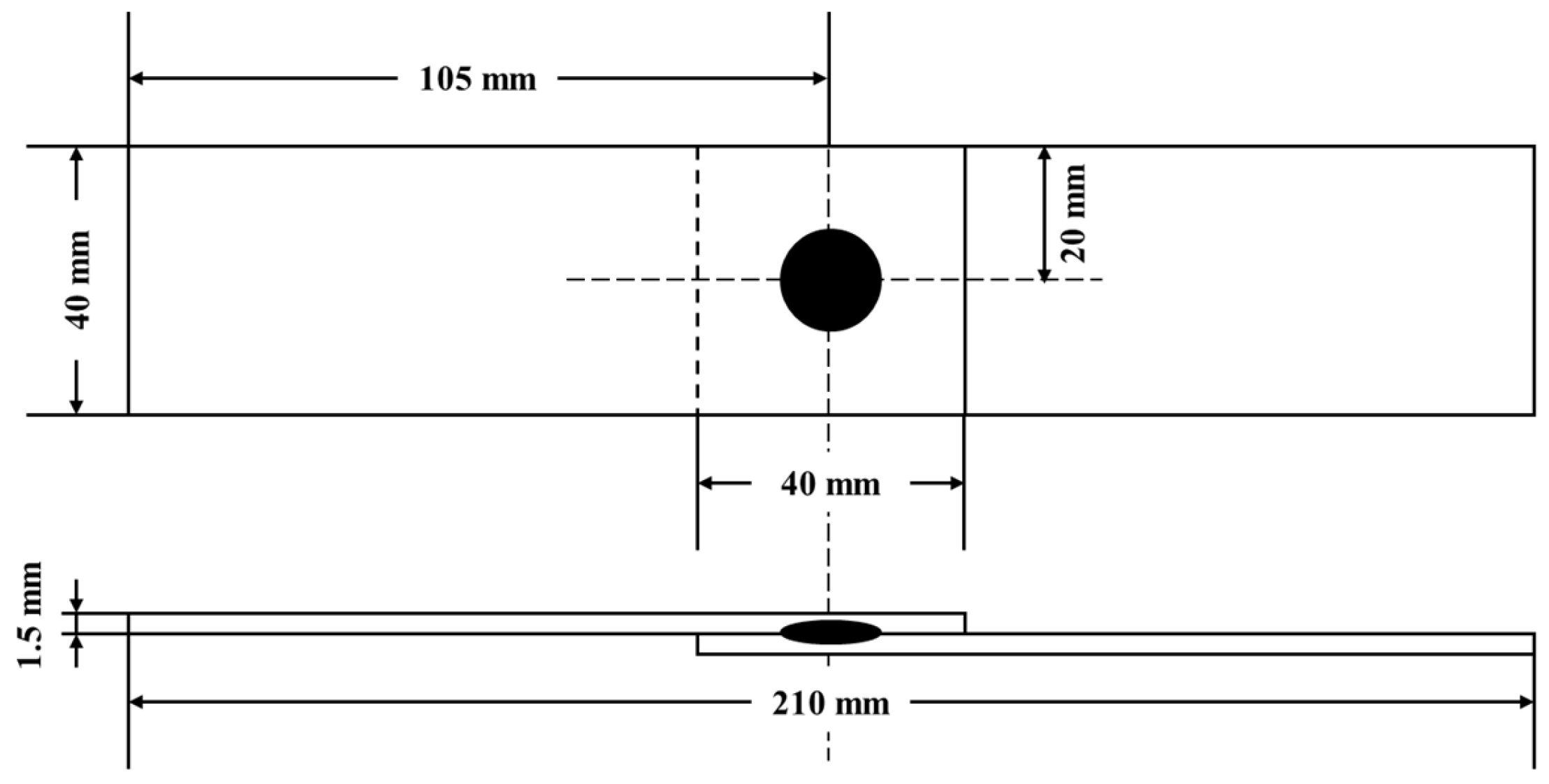
2.4. Tensile Shear Strength Test

Tensile shear strength test was conducted to evaluate the weldability of C 316L stainless steel and AM 316L stainless steel. The test piece was manufactured as shown in Figure 2 according to the weldability evaluation standard. The fabricated specimen was tested through a tensile tester. The tensile test was performed at a speed of 3 mm/min, and the test was terminated when fracture occurred between welded joints. After the tensile test, the fracture surface analysis and maximum load values were analyzed.

2.5. Welding Conditions

Table 2 shows the welding conditions in experiments. The Cu-Cr dome-type electrodes of tip diameter of 6 mm and tip radius of 40 mm were used. The electrode force and hold time were fixed at 3.4 kN and 167 ms, respectively. The welding time was set to 300, 400, and 500 ms. In CCC mode, the welding progressed between 3.0 kA and 6.5 kA. In CPC mode, the welding was between 7.0 kW and 8.0 kW.

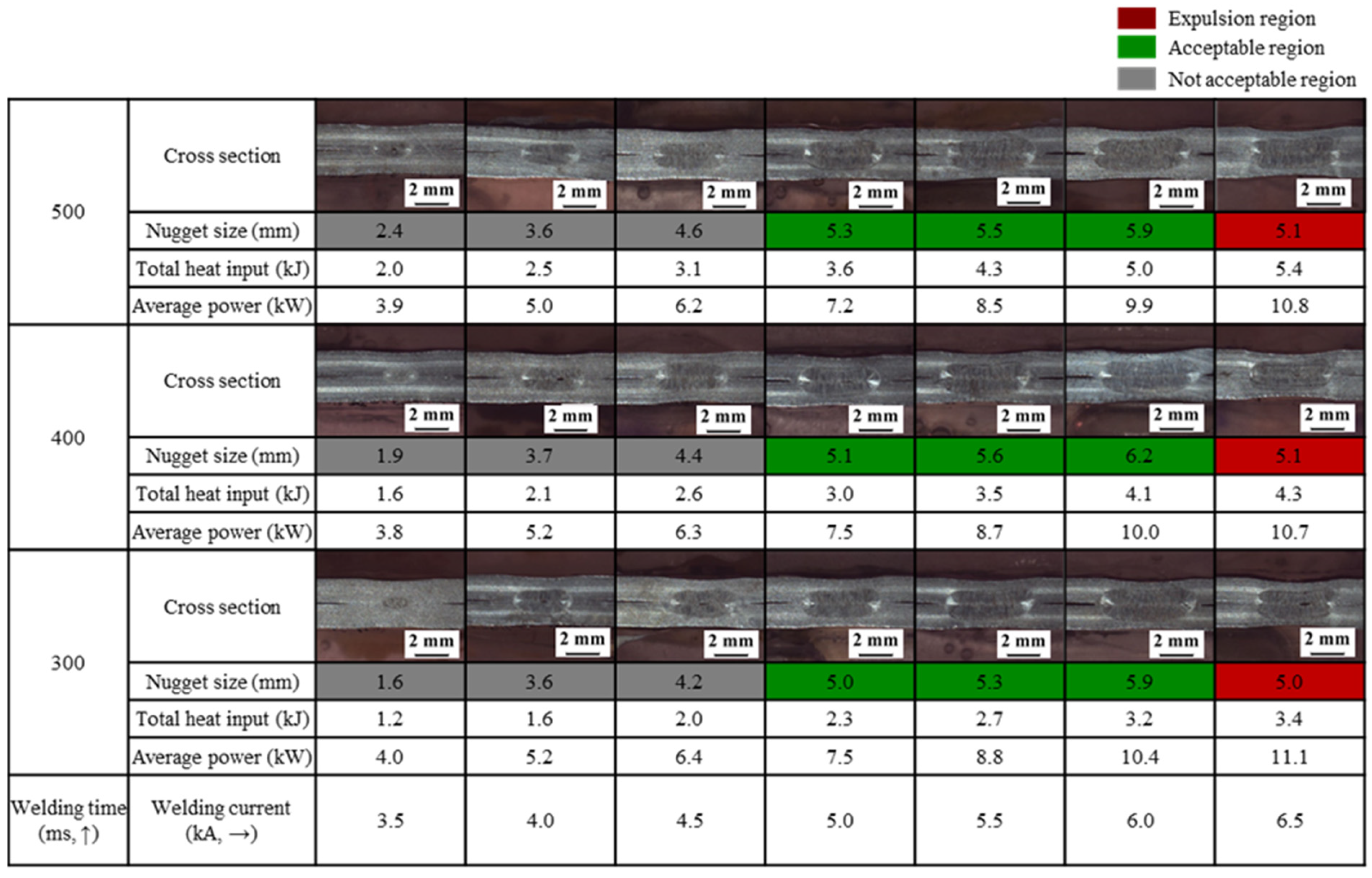
3. Results and Discussion

3.1. Weld Lobe Analysis for Two Materials

Welding experiments were performed on AM 316L stainless steel and C 316L stainless steel, respectively, and cross-section analysis was conducted thereafter. The weld lobe of the C 316L stainless steel is shown in Figure 3 and that of AM 316L stainless steel is shown in Figure 4. The horizontal and vertical axes of the weld lobe represent the welding current and welding time, respectively. The entire weld lobe was divided into three sections. When the nugget diameter was not acceptable, the region was marked in white. When it was acceptable, the region was marked in green. When expulsion occurred, the region was marked in red. The welding experiment was carried out while the welding current was increased by 0.5 kA under the application of the CCC mode. The lower limit of the weld lobe was represented by the part where welding was not performed mainly owing to a lack of energy, while the upper limit was represented by the part where expulsion, which is the welding defect, occurred due to excessive energy. Cross-section analysis was conducted after the welding experiment, and the weld lobe was constructed for each material according to the nugget diameter. In the weld lobe, the nugget diameter, average power, and total heat input for each condition are shown. The average power and total heat input were derived using Equations (1) and (2), respectively. The nugget diameter was classified as acceptable and not acceptable diameters based on the AWS D8. 1 standard. According to this standard, the acceptable diameter of the nugget is greater than or equal to 5.0 mm. Under each condition, the average power and total heat input were obtained using Equations (2) and (3), and they were shown together with the nugget diameter. In the weld lobe for C 316L stainless steel, the minimum nugget diameter was sufficed when the welding power was in the 7.2–10.4 kW range and the total heat input was in the 2.3–5.0 kJ range under welding currents of 5.0, 5.5, and 6.0 kA. When the welding current was 6.5 kA, expulsion occurred. By contrast, in the weld lobe for AM 316L stainless steel, no section sufficed the minimum nugget diameter, and expulsion occurred when the welding current was 5.0 kA.
Waveform analysis was conducted to analyze the cause of the difference in weldability between the two materials. Figure 5 shows the dynamic resistance of both the materials with respect to the welding time when the welding current was 4.5 kA. The dynamic resistance was obtained using Equation (1). Under all conditions, AM 316L stainless steel showed a higher dynamic resistance compared with C 316L stainless steel during welding.
Figure 6 shows the welding power of both the materials according to the welding time when the welding current was 5.0 kA. At a welding current of 5.0 kA, expulsion occurred in AM 316L stainless steel but not in C 316L stainless steel. Under all conditions, AM 316L stainless steel exhibited higher welding power than the C 316L stainless steel at the beginning of welding. As considerable energy is generated at the beginning of welding, expulsion occurred when the welding time was approximately 100 ms, and the welding power sharply decreased. It was observed that expulsion occurred in AM 316L stainless steel at a lower current during welding compared with C 316L stainless steel because energy was rapidly generated at the beginning of welding. The reason why AM 316L stainless steel exhibited different trends compared with C 316L stainless steel could be attributed to many defects. Resistance spot welding is on the principle of Joule’s law of heating. According to the research [21], the Joule heating effect highly hinges on the material resistivity affected by the electron scattering in the defects, including dislocations, grain boundaries, porosity, and so on. In other words, the higher these defects are, the more electron scattering occurs, increasing dynamic resistance and generating more heat. The steel fabricated via additive manufacturing (AM) contains many defects, such as subgrains and dislocation, due to fast cooling rates [5]. Furthermore, even though the pore fraction in AM 316L stainless steel was relatively low, these pores also could affect electron scattering, resulting in more heat [22]. To sum up, these defects in AM 316L stainless steel could give rise to these different trends in comparison with C 316L stainless steel.

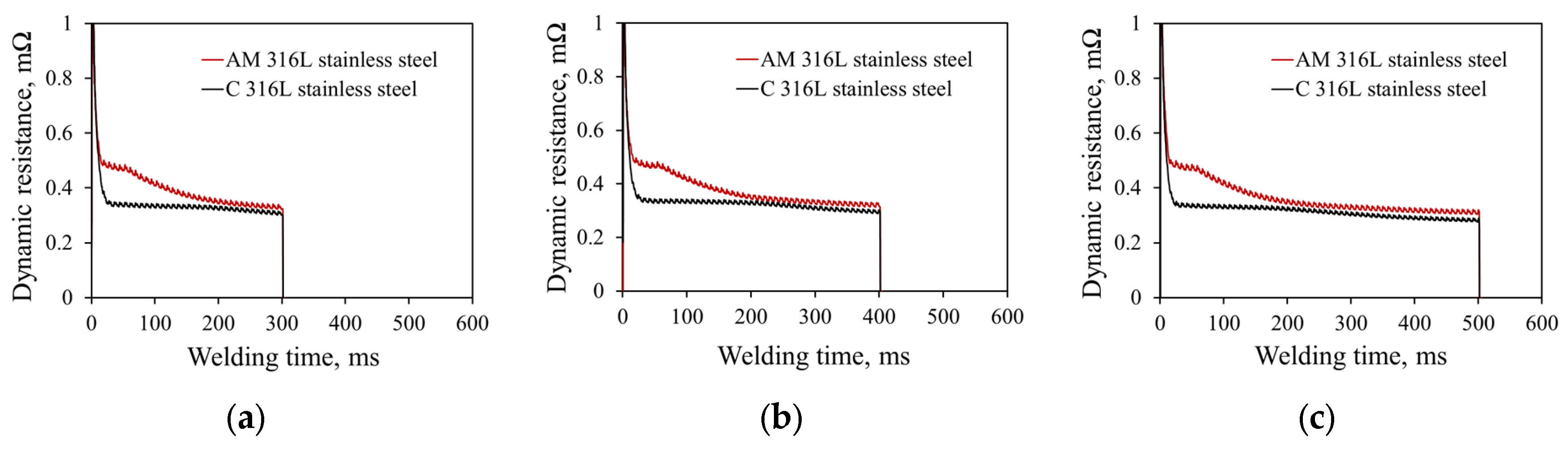
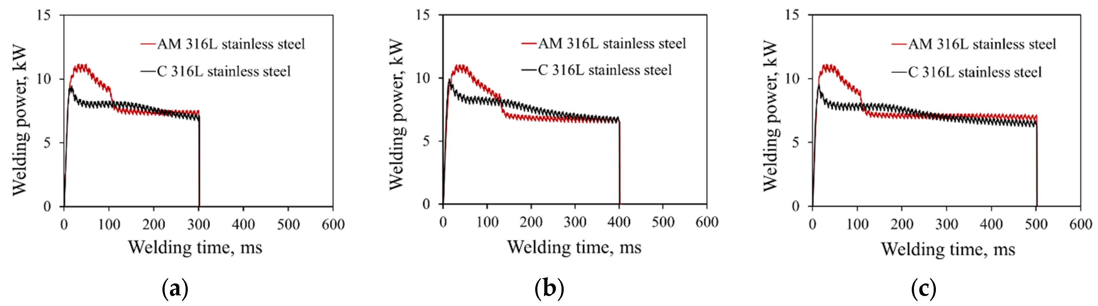
3.2. Analysis of Two Materials under Same Heat Input Condition

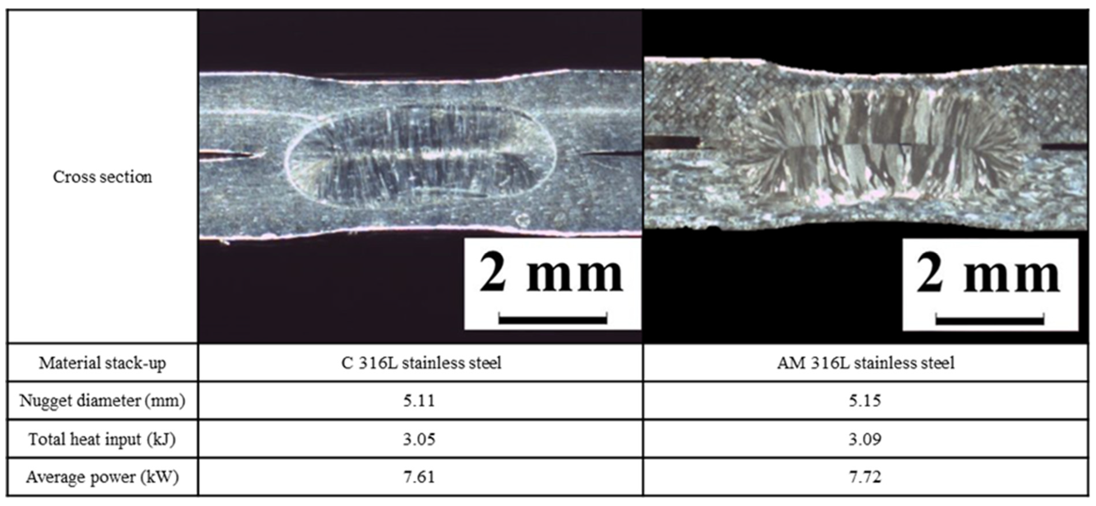
3.2.1. Cross-Section Analysis

Weldability analysis was conducted under the same heat input condition to analyze the characteristics between AM 316L stainless steel and C 316L stainless steel. Figure 7 shows the cross section, nugget diameter, total heat input, and average power for each material under the same heat input condition. The total heat input measured after welding was 3.05 kJ and 3.09 kJ for 316L stainless steel and AM stainless steel, respectively. The heat inputs applied to the two materials were similar, and the nugget diameters were found to be 5.11 and 5.15 mm, respectively. This indicates that there is no difference in nugget diameter between the two materials under the same heat input condition.

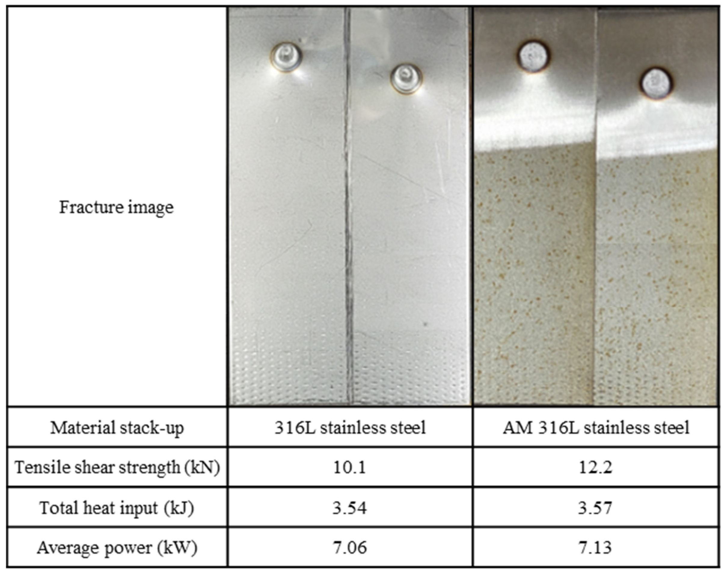
3.2.2. Tensile Shear Strength Test

Next, as stated in a previous experiment, the tensile shear strength test was conducted after performing welding for the two materials under the same heat input condition. Figure 8 shows the fracture image, tensile shear strength, total heat input, and the average power for both the materials under the same heat input condition. The total heat input measured after welding was 3.54 kJ and 3.57 kJ for C 316L stainless steel and AM stainless steel, respectively. In the results of the tensile shear strength test, the strength of C 316L stainless steel was 10.1 kN and that of AM 316L stainless steel was 12.2 kN, showing that the strength of AM 316L stainless steel was greater by approximately 2.1 kN. As stated in the experiment results in Section 3.2.1, the nugget diameter was similar under the same heat input condition, but there was a difference in tensile strength.

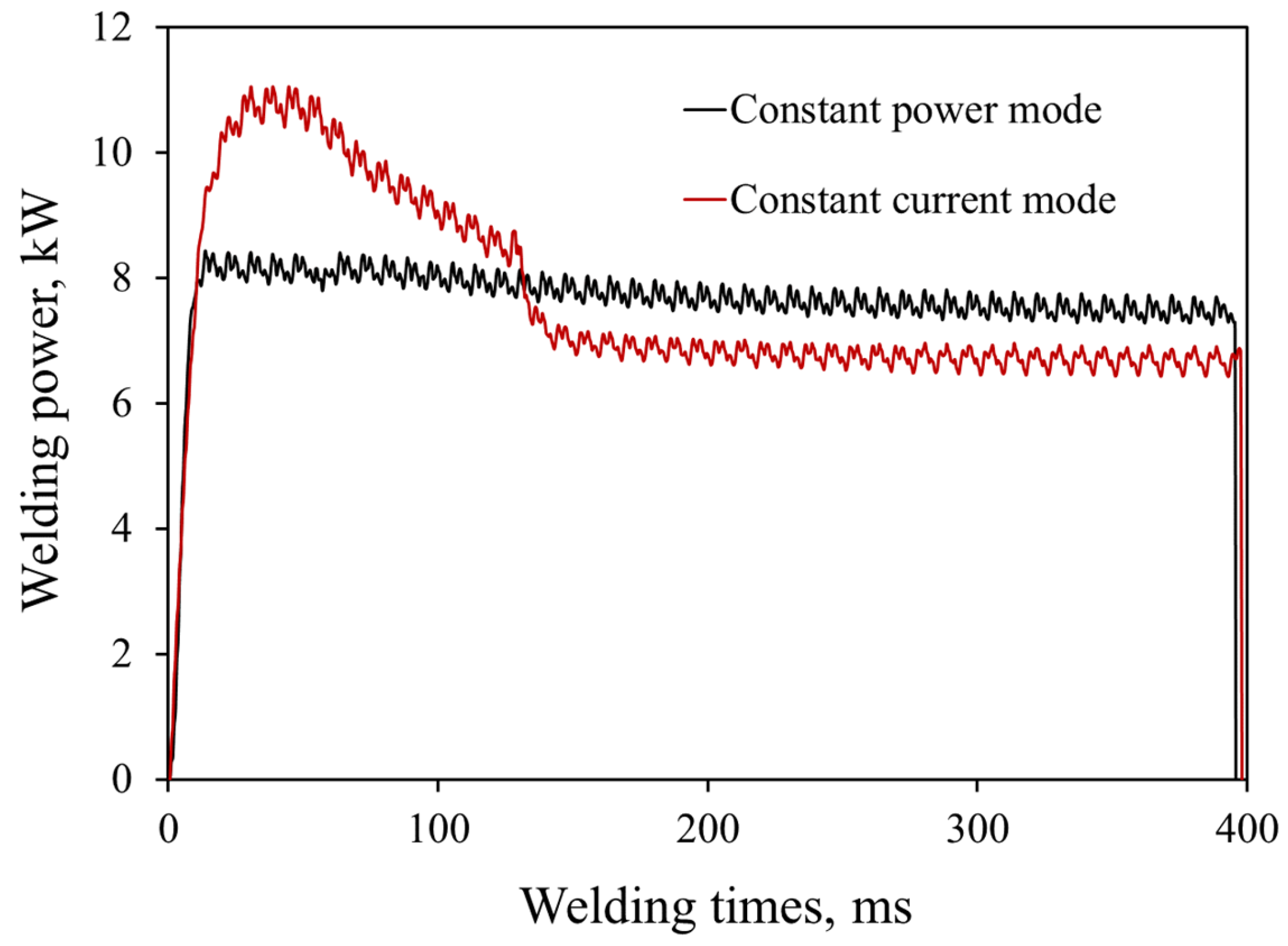
3.2.3. Welding Signal Analysis

Next, welding signal analysis was conducted for C 316L stainless steel and AM 316L stainless steel under the same heat input condition. Figure 9 shows the welding current, welding voltage, and dynamic resistance for the two materials. For the welding current and welding voltage shown in Figure 9a,b, there is no significant difference between the two materials. In the case of the dynamic resistance shown in Figure 9c, however, there is a difference between the two materials. In the dynamic resistance waveform, AM 316L stainless steel exhibited higher resistance than C 316L stainless steel. Because this difference in resistance cannot sufficiently explain the difference in strength between the two materials, hardness analysis was conducted.

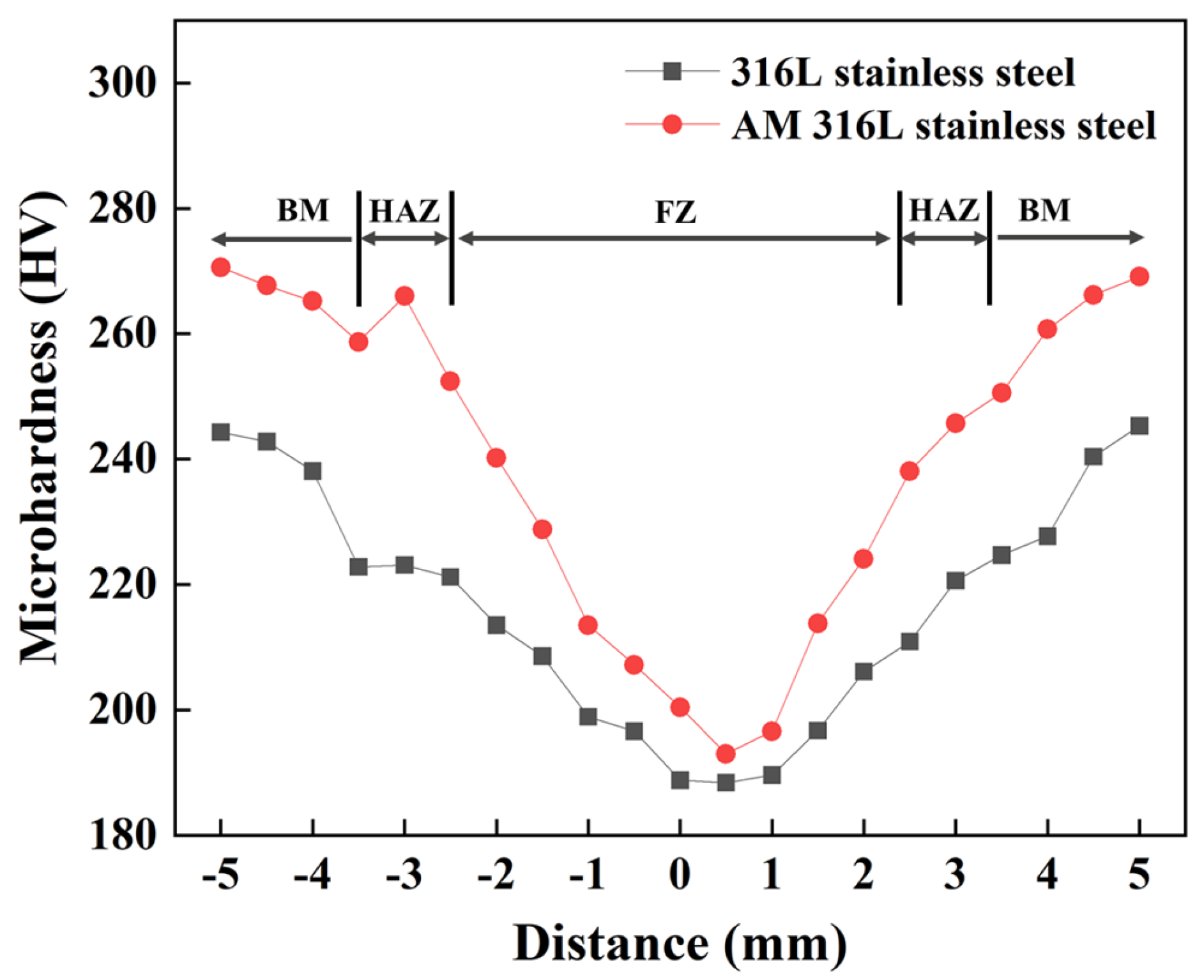
3.2.4. Microhardness

A series of microhardness measurements were performed along the center line above the weld nugget at a regular interval of 0.5 mm using a Vickers hardness tester (Model: HM-210B). An indentation load of 100 g with a dwell time of 10 s was used in the process of the measurements. Vickers microhardness measurements were conducted on the base metal (BM), heat-affected zone (HAZ), and fusion zone (FZ) of welded C 316L stainless steel and AM 316L stainless steel samples. As seen in Figure 10, the microhardness of the FZ in both samples was lower than that of the HAZ and the BM. This may be attributed to the fact that when welding process is carried out in a natural atmosphere and the samples are cooled in air, the grains might grow in the FZ, thus reducing the value of microhardness in the FZ [16,23]. Furthermore, the HAZ that is close to the BM exhibited a fast cooling rate, and it generated a relatively fine grain structure. In contrast, the cooling rates of the HAZ near the FZ was low, resulting in an increase in the grain size [3]. Thus, the reduction of the hardness of the FZ could be explained by the difference in the cooling rates. As far as BM is concerned, the AM 316L stainless steel sample possessed a hardness value of approximately 260 HV. In contrast, a lower hardness of approximately 220 HV was observed in the C 316L stainless steel specimen. This is because the AM 316L stainless steel exhibited rapid cooling rates [5], which further resulted in an increase in the dislocation density. Thus, it could be conjectured that the substantial increment in the dislocation density due to the fast cooling rates explains why the hardness of the AM 316L stainless steel was greater than that of the C 316L stainless steel. In terms of the FZ and HAZ, the hardness of the AM 316L stainless steel was slightly greater than that of C 316L stainless steel.

3.3. Improved Weldability through CPC Mode

To improve the weldability of AM 316L stainless steel, welding was performed through the application of the CPC mode. The integration of the CPC mode for resistance spot welding ensures good stability and a larger nugget diameter compared with the CCC mode, which involves the generation of excessive energy at the beginning of welding because constant energy is applied [24]. Therefore, by integrating the CPC model to the AM 316L stainless steel, it is possible to apply more energy to the weld zone because a constant energy can be applied unlike the energy generated excessively at the beginning as shown in Figure 6. Figure 11 shows the cross-section analysis results under the application of the CPC mode to AM 316L stainless steel. The welding experiment was performed by increasing the welding power by 0.5 kW. The lower limit of the weld lobe was represented by the part where welding was not performed due to a lack of energy while the upper limit was represented by the part where expulsion, which is the welding defect, occurred due to excessive energy. The nugget diameter, average power, and total heat input for each condition are shown in the weld lobe. In the experiment results, expulsion occurred when the welding power was 8.0 kW, mainly due to the excessive concentration of energy. However, in a few sections, the nugget diameter sufficed the standard except when the welding power was 7.0 kW, and the welding time was 300 ms. Comparison was made with Figure 4, which is the result of applying CCC mode to AM 316L stainless steel. In Figure 4, there is no welding section that satisfies the proper nugget diameter. In contrast, in Figure 11, which is the result of cross-section analysis with CPC mode applied, a section satisfying sufficient nugget size appears. It can be judged that the weldability is improved by applying the CPC mode to the material for which the proper welding section does not appear in the previous experiment. We analyzed the physical phenomenon that makes the CPC mode better to improve the weldability of AM 316L stainless steel. From the examination of the total heat input, it was observed that more energy could be applied to the weld zone without the occurrence of expulsion compared with Figure 4 wherein the CCC mode was applied. Figure 12 shows the welding power waveforms of the CPC and CCC modes. Under the corresponding welding conditions, the total heat input of the CCC mode was 3.0 kJ, and expulsion occurred due to high heat input at the beginning. On the other hand, the total heat input of the CPC mode was 3.1 kJ, and no expulsion occurred even though higher energy was applied compared with the CCC mode. Therefore, when AM 316L stainless steel was welded through the CPC mode, more energy could be applied, thus ensuring optimal welding.

4. Conclusions

In this study, weldability was analyzed for conventional (C) 316 stainless steel and additive manufactured (AM) 316L stainless steel, and it can be inferred that the weldability of AM 316L stainless steel was improved considerably. The outcomes of the study are summarized below.
(1)
The lobe diagram and appropriate welding section were derived for the two materials according to the nugget diameter, and the difference between the two materials was analyzed through waveform analysis.
(2)
When the same heat input was applied to the two materials, the nugget diameter was identical. However, there was a difference in tensile shear strength value. This difference could be explained by the hardness analysis results.
(3)
The weldability of AM 316L stainless steel was improved and, thus, an appropriate nugget diameter could be secured through the application of the CPC mode.
The study findings contribute to the research on welding techniques for additive manufacturing technology. The findings may be significant to the additive manufacturing industry because they present resistance spot weldability analysis and improvement for conventional 316L stainless steel and additive manufactured 316L stainless steel. In the future, material characteristics may be analyzed through various structural analysis methods.

Author Contributions

Conceptualization, S.K., J.P. and J.Y.; methodology, S.K. and S.P.; software, D.-Y.K.; validation, J.Y.; formal analysis, S.K. and M.K.; investigation, S.P.; writing—original draft preparation, S.K. and S.P.; writing—review and editing, J.P. and J.Y.; supervision, J.Y.; project administration and funding acquisition, J.Y. All authors have read and agreed to the published version of the manuscript.

Funding

This study has been conducted with the support of the Korea Institute of Industrial Technology as “The dynamic parameter control based smart welding system module development for the complete joint penetration weld (kitech EH-21-0003)”.

Institutional Review Board Statement

Not applicable.

Informed Consent Statement

Not applicable.

Data Availability Statement

Not applicable.

Conflicts of Interest

The authors declare no conflict of interest.

References

  1. Kong, D.; Dong, C.; Ni, X.; Zhang, L.; Yao, J.; Man, C.; Cheng, X.; Xiao, K.; Li, X. Mechanical properties and corrosion behavior of selective laser melted 316L stainless steel after different heat treatment processes. J. Mater. Sci. Technol. 2019, 35, 1499–1507. [Google Scholar] [CrossRef]
  2. Saeidi, K.; Gao, X.; Zhong, Y.; Shen, Z. Hardened austenite steel with columnar sub-grain structure formed by laser melting. Mater. Sci. Eng. A 2015, 625, 221–229. [Google Scholar] [CrossRef]
  3. Danial, K.; Mostafaei, A.; Amadeh, A. Resistance spot welding joints of AlSI 316L austenitic stainless steel sheets: Phase transformations, mechanical properties and microstructure characterizations. J. Mater. Sci. 2014, 61, 251–263. [Google Scholar]
  4. Cheng, L.; Yansong, Z. Fusion zone characterization of resistance spot welded maraging steels via selective laser melting. J. Mater. Process. Technol. 2019, 273, 116253. [Google Scholar]
  5. Pham, M.S.; Dovgyy, B.; Hooper, P.A. Twinning induced plasticity in austenitic stainless steel 316L made by additive manufacturing. Mater. Sci. Eng. A 2017, 704, 102–111. [Google Scholar] [CrossRef]
  6. Elif, K.; Yahya, B. Additive manufacturing method and different welding applications. Mater. Res. Technol. 2020, 9, 11424–11438. [Google Scholar]
  7. Huysmans, S.; Peeters, E.; De Bruycker, E.; De Prins, K. Weldability study of additive manufactured 316L austenitic stainless steel components—Welding of AM with conventional 316L components. Mater. Sci. 2021, 65, 1415–1427. [Google Scholar] [CrossRef]
  8. Järvinen, J. Welding of Additively Manufactured Stainless Steel Parts: Comparative Study Between Sheet Metal and Selective Laser Melted Parts. Mater. Sci. 2014, 51–60. [Google Scholar]
  9. Murat, V.; Ahmet, A. On the resistance spot weldability of galvanized interstitial free steel sheets with austenitic stainless steel sheets. J. Mater. Process. Technol. 2004, 153–154, 1–6. [Google Scholar]
  10. Ruizhi, Z.; Craig, B.; Ville-Pekka, M.; Dafni, D.; Ben, B.; Heidi, P.; Antti, S.; Leroy, G. Mechanical properties and microstructure of additively manufactured stainless steel with laser welded joints. Mater. Des. 2021, 208, 109221. [Google Scholar]
  11. Ville-Pekka, M.; Joonas, P.; Antti, S. Weldability of additive manufactured stainless steel. Phys. Procedia 2016, 83, 807–817. [Google Scholar]
  12. Giuseppe, C.; Sabina, L.C.; Antonio, D.L. Laser-arc hybrid welding of wrought to selective laser molten stainless steel. Int. J. Adv. Manuf. Technol. 2013, 68, 209–216. [Google Scholar]
  13. Jingjing, Y.; Yun, W.; Fangzhi, L.; Wenpu, H.; Guanyi, J.; Zemin, W.; Xiaoyan, Z. Weldability, microstructure and mechanical properties of laser-welded selective laser melted 304 stainless steel joints. J. Mater. Sci. 2019, 35, 1817–1824. [Google Scholar]
  14. Laitinen, V. Weldability of Powder Bed Fusion Fabricated Stainless Steel 316L Sheets to Cold Rolled Sheet Metal. Master’s Thesis, LUT University, Lappeenranta, Finland, 2015. [Google Scholar]
  15. Teerawut, K.; Kannachai, K. Resistance Spot Welding of SUS316LAustenitic/SUS425 Ferritic Stainless Steels: Weldment Characteristics, Mechanical Properties, Phase Transformation and Solidification. Metals 2019, 9, 710. [Google Scholar]
  16. Bayram, K.; Ramazan, K.; Süleyman, G.; Fatih, H. An effect of heat input, weld atmosphere and weld cooling conditions on the resistance spot weldability of 316L austenitic stainless steel. J. Mater. Process. Technol. 2008, 195, 327–335. [Google Scholar]
  17. ISO 14273; International Organization for Standardization: Specimen Dimensions and Procedure for Shear Testing Resistance Spot, Seam and Embossed Projection Welds. ISO: Geneva, Switzerland, 2001; pp. 3–4.
  18. Su, Z.-W.; Xia, Y.-J.; Shen, Y.; Li, Y.-B. A novel real-time measurement method for dynamic resistance signal in medium frequency, DC resistance spot welding. Meas. Sci. Technol. 2020, 31, 055011. [Google Scholar] [CrossRef]
  19. Cho, Y.; Rhee, S. Primary circuit dynamic resistance monitoring and its application to quality estimation during resistance spot welding. Weld. J. 2002, 81, 104-s–111-s. [Google Scholar]
  20. Kim, S.; Hwang, I.; Kim, D.Y.; Kim, Y.M.; Kang, M.; Yu, J. Weld-quality prediction algorithm based on multiple models using process signals in resistance spot welding. Metals 2021, 11, 1459. [Google Scholar] [CrossRef]
  21. Zhang, X.; Li, H.; Zhan, M. Mechanism for the macro and micro behaviors of the Ni-based superalloy during electrically-assisted tension: Local Joule heating effect. J. Alloy. Compd. 2018, 742, 480–489. [Google Scholar] [CrossRef]
  22. Sumirat, I.; Ando, Y.; Shimamura, S. Theoretical consideration of the effect of porosity on thermal conductivity of porous materials. J. Porous Mater. 2006, 13, 439–443. [Google Scholar] [CrossRef]
  23. Dursun, Ö. An effect of weld current and weld atmosphere on the resistance spot weldability of 304L austenitic stainless steel. Mater. Des. 2008, 29, 597–603. [Google Scholar]
  24. Yu, J.; Choi, D.; Rhee, S. Improvement of Weldability of 1 GPa Grade Twin-Induced Plasticity Steel. Weld. J. 2014, 93, 78s–84s. [Google Scholar]
Figure 1. Experimental setup and schematic diagram of the monitoring system for resistance spot welding process.
Metals 13 00837 g001
Figure 2. Test pieces for weldability analysis.
Metals 13 00837 g002
Figure 3. Weld lobe of C 316L stainless steel through CCC mode.
Metals 13 00837 g003
Figure 4. Weld lobe of AM 316L stainless steel through CCC mode.
Metals 13 00837 g004
Figure 5. Dynamic resistance waveform of AM 316L stainless steel and C 316L stainless steel according to welding time: (a) welding time: 300 ms; (b) welding time: 400 ms; (c) welding time: 500 ms.
Metals 13 00837 g005
Figure 6. Welding power waveform of AM 316L stainless steel and C 316L stainless steel according to welding time: (a) welding time: 300 ms; (b) welding time: 400 ms; (c) welding time: 500 ms.
Metals 13 00837 g006
Figure 7. Cross-section analysis of C 316L stainless steel and AM 316L stainless steel.
Metals 13 00837 g007
Figure 8. Tensile shear strength test of C 316L stainless steel and AM 316L stainless steel.
Metals 13 00837 g008
Figure 9. Welding signal of C 316L stainless steel and AM 316L stainless steel: (a): welding current; (b): welding voltage; (c): dynamic resistance.
Metals 13 00837 g009
Figure 10. Microhardness profiles of welded C 316L and AM 316L specimens.
Metals 13 00837 g010
Figure 11. Weld lobe of AM 316L stainless steel through CPC mode.
Metals 13 00837 g011
Figure 12. Welding power waveform of CCC mode and CPC mode.
Metals 13 00837 g012
Table 1. Chemical composition of C 316L stainless steel and AM 316L stainless steels (wt %).
MaterialElement
CSiMnPSNiCrMoFe
C 316L
stainless steel
0.0160.631.070.0120.00110.416.82.03Balance
AM 316L stainless steel0.0170.690.960.0010.00412.717.02.56Balance
Table 2. Welding conditions.
ItemsConditions
Electrode typeTip diameter: 6 mm
Materials: Cu-CR
Electrode force (kN)3.4
Squeeze time (ms)167
Hold time (ms)167
Welding time (ms)300, 400, 500
Welding current (CCC mode, kA)3.0~6.5
Welding power (CPC mode, kW)7.0~8.0
Disclaimer/Publisher’s Note: The statements, opinions and data contained in all publications are solely those of the individual author(s) and contributor(s) and not of MDPI and/or the editor(s). MDPI and/or the editor(s) disclaim responsibility for any injury to people or property resulting from any ideas, methods, instructions or products referred to in the content.

