Abstract
A solid-phase diffusion welding of coarse-grained and ultrafine-grained (UFG) specimens of titanium near-α alloy Ti-5Al-2V used in nuclear power engineering was made by Spark Plasma Sintering. The failure of the welded specimens in the conditions of hot salt corrosion and electrochemical corrosion was shown to have a preferentially intercrystalline character. In the case of the presence of macrodefects, crevice corrosion of the welded joints was observed. The resistance of the alloys against the intercrystalline corrosion was found to be determined by the concentration of vanadium at the titanium grain boundaries, by the size and volume fraction of the β-phase particles, and by the presence of micro- and macropores in the welded joints. The specimens of the welded joints of the UFG alloy are harder and have a higher resistance to hot salt corrosion and electrochemical corrosion.
1. Introduction
At present, titanium α- and near-α alloys (alloys of Ti-Al-V, Ti-Al-Zr, Ti-Al-Mo-V, etc., systems) are used widely in marine engineering, steam turbines, nuclear power engineering, etc. [1,2,3,4,5,6,7]. Enhanced requirements of strength, ductility, fatigue strength, corrosion and radiation resistance, heat resistance, etc., are imposed onto the titanium alloys used in nuclear power engineering [3,4,5,6,7,8,9,10,11].
Traditionally, the enhancement of the mechanical properties and of the performance characteristics of the titanium alloys are provided by means of optimization of their chemical composition as well as by choice of regimes of thermal and deformation treatments [1,2,3,4,5,6,8,10]. Formation of an ultrafine-grained (UFG) microstructure of the titanium alloys using the severe plastic deformation (SPD) method is one of the most promising methods for increasing the performance characteristics of these. The Equal Channel Angular Pressing (ECAP) [12,13], High-Pressure Torsion [14,15], Rotary Swaging [16,17], Multiaxial Forging/Pressing [18,19], etc. are used to form the UFG microstructure in the Ti alloys most often. The UFG titanium alloys obtained by SPD, are featured by enhanced strength [14,16,17,18,19], fatigue resistance [20,21,22], creep resistance [23,24], corrosion resistance [25,26], ductility at high temperatures [19,24,27], etc. This allows for fabricating lighter, stronger, and more reliable structural elements from the UFG titanium alloys.
From the viewpoint of application of the Ti alloys in nuclear engineering, the opportunity to ensure strength and corrosion resistance by means of the use of SPD is important. At present, the forming of the UFG microstructure is commonly accepted to result in increased strength of the Ti alloys [12,13,14,17,18,19]. The issue of high corrosion resistance of the UFG Ti and α-Ti alloys is still ambiguous. Most publications demonstrated UFG Ti to have a higher corrosion resistance because of forming denser and thicker native oxide surface layers [25,28,29,30,31]. However, there are some works where the opposite results were reported, evidencing the reduction in the corrosion resistance of UFG Ti [32,33,34]. It was also noted in [34] that texture formation during SPD has a greater influence on the corrosion resistance of titanium than on the grain size. In [35,36], it was shown that an increase in the oxygen concentration in the surface layers of Ti may occur at SPD, whereas the hydrogenation of the UFG Ti surface takes place after long exposure to an acid ambient. This may lead to a change in the corrosion rate of acids. At short testing times, UFG Ti may possess a lower corrosion rate compared to the coarse-grained specimens, whereas at long times—the corrosion rate may increase considerably and exceed the corrosion rate of coarse-grained Ti [36].
The problem with developing technology for welding the UFG titanium alloys is an important one limiting their wide application. At present, argon arc beam or electron beam technologies for welding titanium alloys are most often used for the fabrication of long workpieces in the industry [3,37,38,39,40]. The welding of specimens using these technologies is associated with the melting of the welded joint region and, hence, does not allow preserving the UFG microstructure in the welded joint. Such novel technologies of solid-phase welding as linear friction welding or friction-stir welding [41,42,43] have not become widely applicable yet due to essential and uncontrolled overheating of the welding zone and pollution of the joint region by external impurities from the processing tool (punch) material. These features of conventional welding technologies result in poor performance characteristics of the welded joints (in particular, of the reduced corrosion resistance [44]) and, hence, may limit the operational reliability and durability of highly responsible metal designs.
Spark Plasma Sintering (SPS) [45,46,47] is one of the novel promising methods for the solid-phase welding and bonding of structural materials, including titanium alloys [48,49]. The efficiency of the application of this method for diffusion welding/bonding of titanium alloys has been demonstrated recently in [50,51]. An opportunity to control and monitor the temperature and time of the diffusion welding, heating rate, and applied pressure to apply step-wise heating regimes with simultaneous monitoring of the shrinkage of the specimens in the course of welding or sintering is an important advantage of SPS [50,51]. An opportunity to implement high heating rates (up to 2500 °C/min) allows for minimizing the grain growth and, hence, allows for preserving the fine-grained microstructure with enhanced performance characteristics in the welded joints. Earlier, SPS was shown to allow high-speed diffusion welding of UFG near-α Ti alloys Ti-5Al-2V [51]. High heating rates allowed for preserving the fine grains in the UFG Ti-5Al-2V alloy, which allowed for reducing the diffusion mass transfer scale, thereby improving the solid-phase diffusion welding intensity at reduced temperatures [51]. The application of SPS to ensure the high operational characteristics of the welded joints in Ti alloys may also be very promising because of the positive effect of pulsed electric current on the mechanical properties of the Ti-Al-V alloys [52]. Note that SPS technology allows for obtaining powder titanium alloys with high mechanical properties and high corrosion resistance (see Table 1 in [53]).
The problem of providing high strength and corrosion resistance of the welded joints of the near-α Ti alloys by joint application of SPD and SPS is of special interest. From the viewpoint of the application of the UFG near-α Ti alloys in nuclear engineering, ensuring that these are highly resistant to hot salt corrosion (HSC) is especially important.
HSC results in severe degradation of the heat-exchange equipment produced from the titanium α- and near-α alloys [3,8,10,54,55,56]. The HSC of the titanium alloys has a complex nature and is a multistage process, in which the chemical and electrochemical destruction in the conditions of action of elevated temperatures, corrosion-aggressive ambient, aces of oxygen as well as (in some cases) of the action of tensile strain are alternating sequentially [54,55,56]. HSC arises at the forming of porous deposits from the hard salts on the surface of the heat exchangers made from Ti alloys at elevated temperatures followed by a concentration of corrosion-aggressive components insolvable in water (chlorides and bromides of alkaline and alkaline earth materials) in these [54,55,56]. As noted in [54,55,56], HSC goes most intensively at direct contact with Ti alloys with crystalline halide salts (chlorides, bromides, iodides) in the presence of water (bound in crystal hydrates, occluded in salt crystals, or present in ambient air) and with air access. This leads to the forming of corrosion products on the surfaces of the Ti alloys in the form of layers of varied composition [54,57]. The size and composition of these layers depend on the alloy composition and on the testing regime. Some authors noted the Ti alloys containing Al to be most susceptible to HSC [58]. At present, most studies on the HSC of Ti alloys are concentrated on the problem of the stress corrosion cracking of high-strength two-phase Ti alloys for the aircraft industry [59,60,61]. Less attention is paid to the problem of HSC in α- and near-α Ti alloys used in nuclear engineering at lower stresses and temperatures. We have found no works devoted to a problem of HSC of welded joints of UFG Ti alloys obtained by SPS. In the present work, the features of corrosion destruction of the welded joints in the UFG near-α Ti alloys were analyzed for the first time. First, results on studying the resistance of the powder titanium alloys obtained by SPS in the HSC conditions were presented in [53].
Note that a positive effect of high-temperature SPD on the resistance of near-α Ti alloys to HSC was reported earlier [26]. This allows expecting joint application of SPD and SPS to allow ensuring a high resistance of the welded joints against HSC.
The present work was aimed at studying the features of destruction of the welded joints of the titanium near-α alloy specimens in the HSC conditions and, in particular, studying the effect of microstructure parameters and SPS modes on the resistance to the HSC of the welded specimens.
2. Materials and Methods
The study focuses on Ti-4.73 wt.% Al-1.88 wt.% V alloy (Russian industrial alloy PT-3V). The PT-3V alloy is an analog of Grade 9 alloy (Ti-(2.5–3.5)% Al-(2–3)%V) but differs from this one by an increased Al content. The PT-3V alloy is one of near-α titanium alloys, with a volume ratio of β-phase which does not exceed 5%. The bars of an alloy of 20 mm in diameter were made by Chepetsky Mechanical Plant Co. (Glazov, Russia) by hot deformation with gradual reduction in temperature from the β-phase range to the (α + β) one (see [62,63,64]). The chemical composition of the alloy is presented in Table 1. The chemical composition of the PT-3V alloy meets the requirements of Russian National Standard GOST 19807-91. General chemical analysis of the alloy is carried out using FOUNDRY®-MasterTM spectrum analyzer (Oxford Instruments, Abingdon, UK). The concentrations of oxygen, nitrogen, carbon, and hydrogen were measured by reductive melting using ELTRA® ON-900 (control over O2, C, N2) and ELTRA® OH-900 (control over H2) analyzers (ELTRA GmbH, Haan, Germany).

Table 1.
Compositions of the titanium alloy PT-3V.
The UFG microstructure in the alloy was formed with ECAP in the Bc route (the number of the ECAP cycles was N = 4, the ECAP temperature was 450 °C, and the ECAP rate was 0.2–0.4 mm/s). ECAP was performed with Ficep® HF400L hydraulic press (Ficep® S.P.A., Varese, Italy). The intersection angle of the operating channel and the output channel was π/2. Before pressing, the specimens of 14 × 14 × 140 mm3 in size were held in the operating channel of the ECAP setup for 10 min. After every ECAP cycle, the workpiece was cooled down to room temperature. Graphite grease laced with molybdenum disulfide (MoS2) was used for ECAP. The accuracy of temperature control during ECAP was ±10 °C.
The diffusion welding of specimens of 7 × 7 × 3.5 mm3 in size was performed using Dr. Sinter® SPS-625 setup (SPS Syntex Inc., Tokyo, Japan). The specimens for investigations were obtained by spark cutting into pieces of 14 × 14 × 140 mm3 in size. Surface roughness varied as a result of polishing with diamond paste at different dispersion levels. The surface roughness in specimens was 40–60 µm.
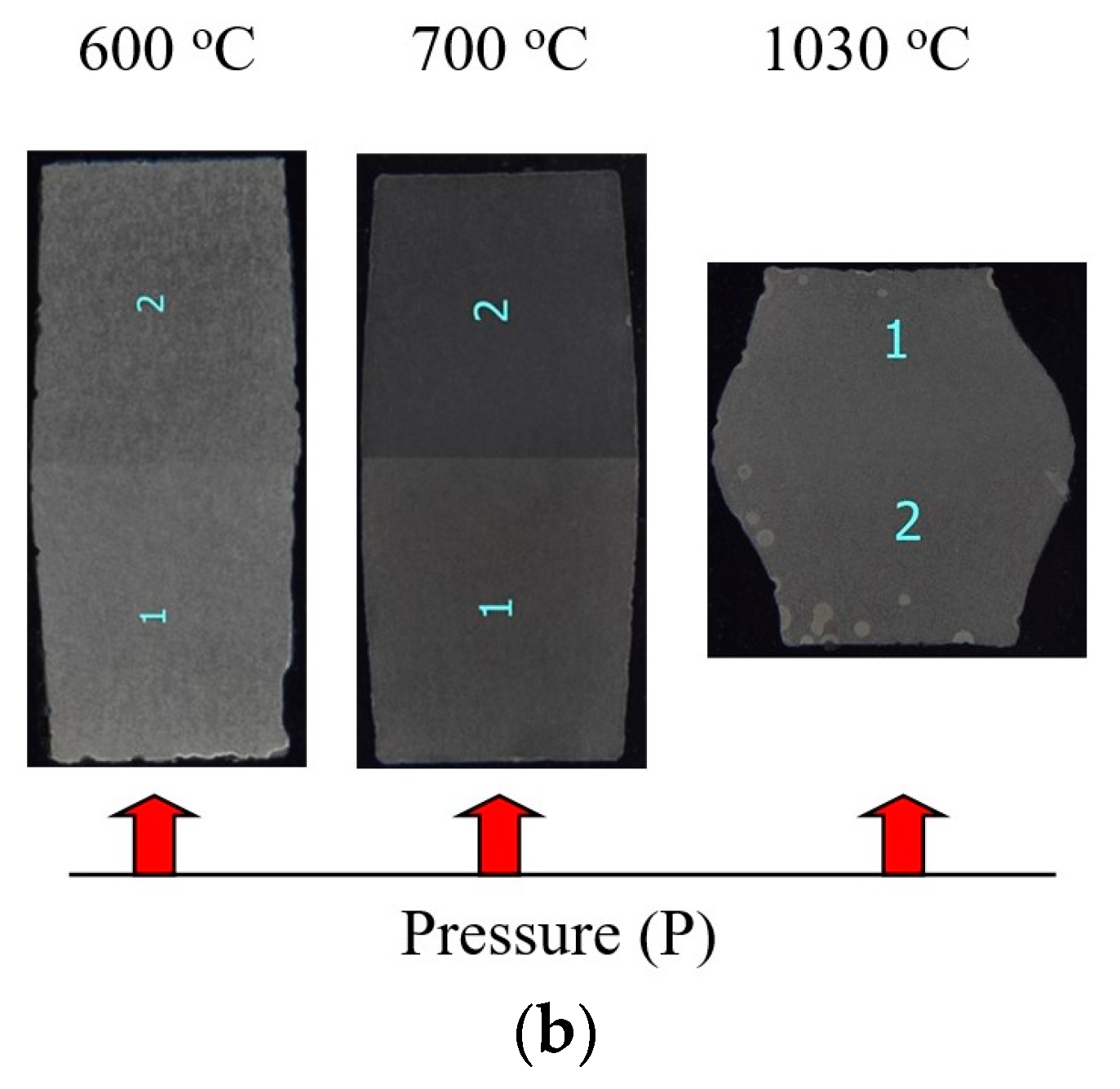
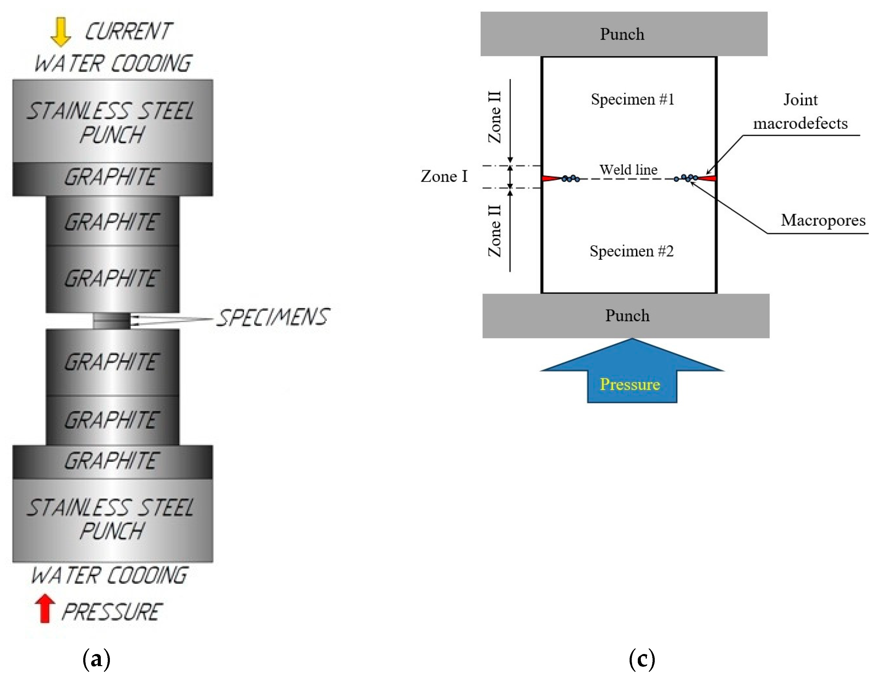
The heating rate Vh varied from 10 to 350 °C/min, the applied uniaxial stress P changed from 50 to 100 MPa, and the processing time varied from 0 to 90 min. The welding temperature T ranged from 600 to 1140 °C: the welding was performed in the α-region (T = 600 °C), near the boundary of the α-β phase transition for the Ti-Al-V alloys (T = 700 °C), at the beginning of the two-phase α+β region (T = 800 °C), and in the region of stable β-phase (T = 1030, 1140 °C) (see [62,63,64]). The accuracy of temperature control was ±10 °C. Welding was performed in vacuum (6 Pa). The diffusion welding of the flat specimens was performed in a free state without the use of the graphite molds (Figure 1a) limiting the expansion process at the plastic deformation of the material in the radial direction. It leads to the formation of the tangent strain acting along the axis of the specimen junction (normal to the axis of the uniaxial stress P = 50, 70, 100 MPa) (Figure 1b).
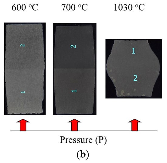
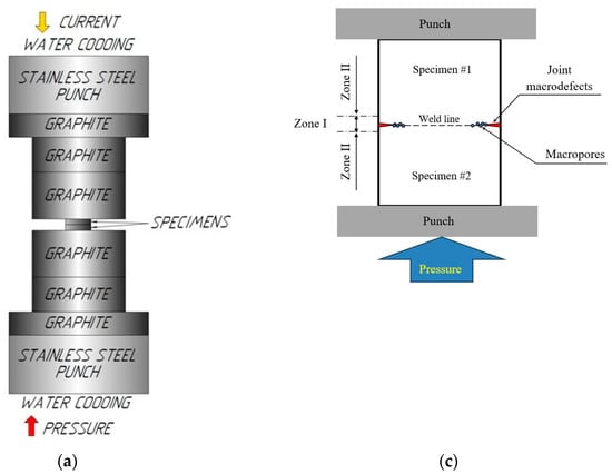
Figure 1.
Scheme of diffusion welding of the titanium alloy specimens by SPS (a). Photographs of coarse-grained specimens obtained at different diffusion welding temperatures (Vh = 100 °C/min, P = 50 MPa, t = 10 min) (b) and the locations of different zones in the cross-sections of the investigated specimens (c). The “1” and “2” in subfigure (b) is specimen #1 and specimen #2 respectively.
The microstructure studies were carried out using Jeol® JSM-6490 scanning electron microscope (SEM, Jeol, Tokyo, Japan) with Oxford Instruments® INCA 350 energy dispersion spectroscopy (EDS) X-ray microanalyzer (Oxford Instruments, Abingdon, UK) and Jeol® JEM-2100 transmission electron microscope (TEM) with JED-2300 EDS microanalyzer (Jeol, Tokyo, Japan). The sizes of the elongated β-phase particles (dβ) and α-phase grains (dα) were measured in two mutually perpendicular directions. The mean size was calculated by averaging the sizes in the longitudinal and transverse directions. The mean uncertainty of determining the sizes of the β-phase particles at the boundaries of the elongated α-grains was about 1 μm, and in the region of the equiaxial α-grains, it was less than 0.5 μm. The mean grain sizes dα and dβ were determined by using GoodGrains 2.0 software.
The microhardness Hv measurements were carried out with Duramin® StruersTM 5 (Struers LLC, Cleveland, OH, USA) with a load of 2 kg. The microhardness measurements were performed along and across the welded joint line. The microhardness measured at the distance of 5 mm away from the weld line was accepted as the microhardness of the alloy. At this distance, the microhardness did not change anymore, and the effect of the weld on the alloy microhardness was minimized (see [51]).
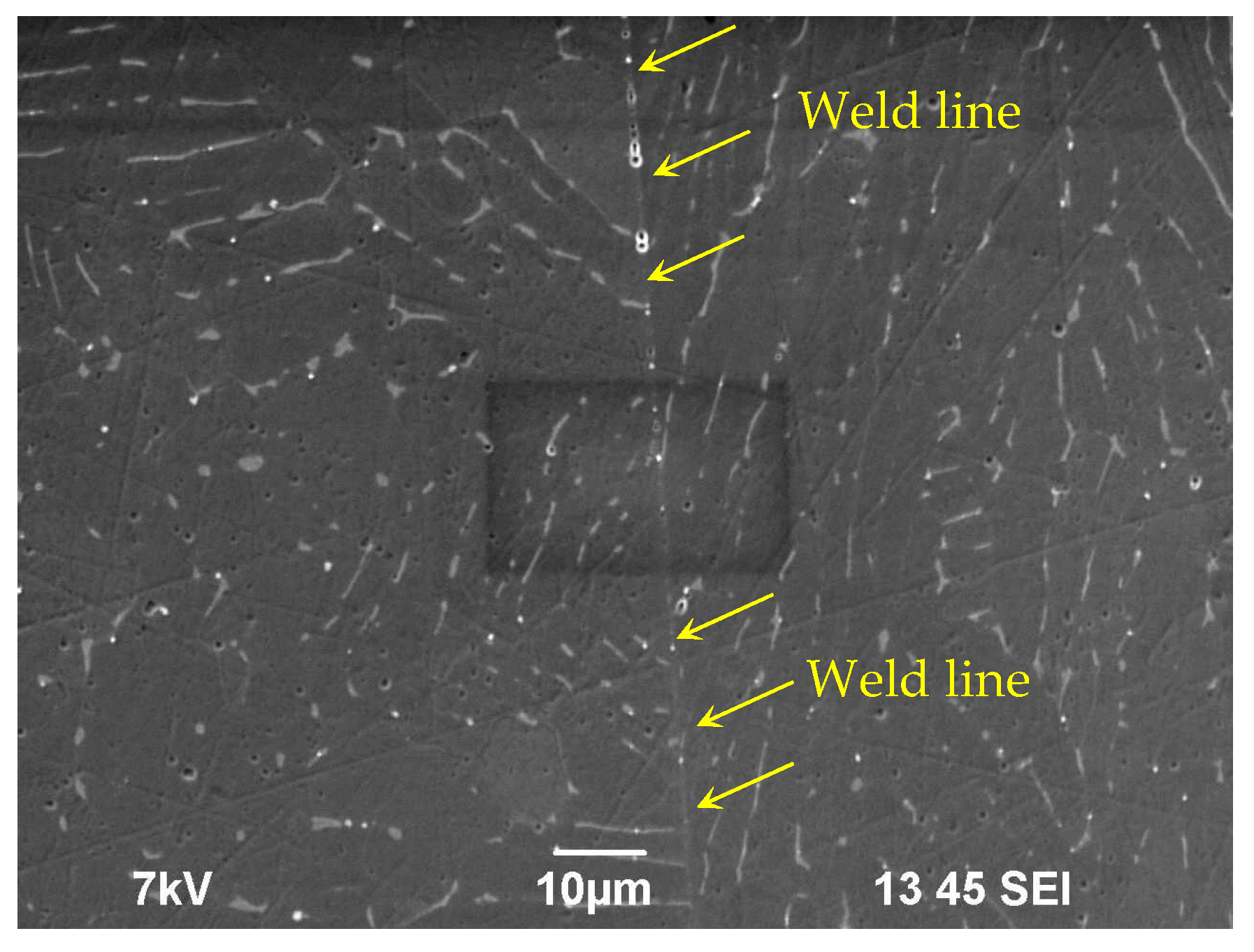
Electrochemical studies were carried out in an aqueous solution of 10% HNO3 + 0.2% HF with R-8 potentiostat-galvanostat (Electrochemical Instruments JSC, Chernogolovlka, Russia). The composition of this solution was selected on the base of a large number of works that study the electrochemical corrosion of α- and near-α titanium alloys. The aqueous solution 10% HNO3 + 0.2% HF is sensitive to the microstructure, chemical, and phase compositions of the grain boundaries in the titanium alloys. The investigations have shown the α- and near-α titanium alloys are to be destroyed in this solution via the intercrystalline corrosion (ICC) mechanism. Since the hot salt corrosion in the α- and near-α titanium alloys has a preferentially intercrystalline character (see [26,65]), we aimed at conducting the laboratory electrochemical tests in the conditions simulating the intercrystalline corrosion as well. Testing was carried out in a glass electrochemical cell of 60 mL in volume, in a still solution. The temperature of the testing was 30 °C. A chlorine-silver reference electrode (EVL-1M4) and a Pt wire as an auxiliary electrode were used in testing. Based on the analysis of the slope in the Tafel potentiodynamic curves [the potential E vs. the current density i in the semilogarithmic axes ln(i) –E], the corrosion current density icorr and the corrosion potential Ecorr were calculated. Prior to testing, the surfaces of the specimens were subjected to mechanical polishing down to 3–5 μm roughness grade. Prior to the electrochemical tests, the specimen surfaces were covered by corrosion-resistant coating except for a ~0.6 mm2 (0.3 × 0.2 mm2) open area located in the center of the specimen cross-section, in the weld area (Figure 2).
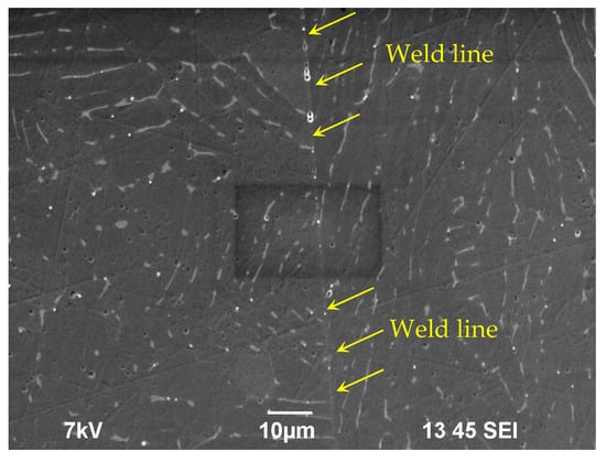
Figure 2.
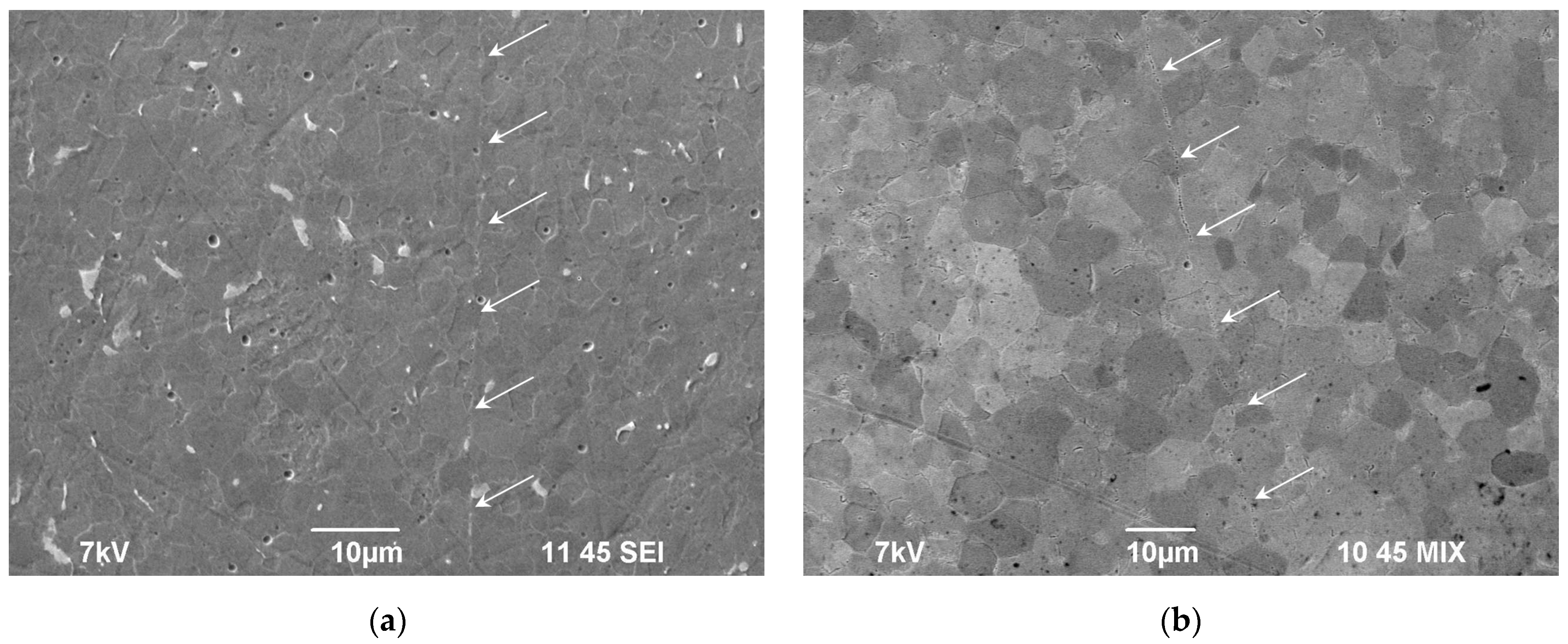
Position of the corrosion area relative to the welded joint. Specimen of the coarse-grained alloy (Vh = 10 °C/min, T = 700 °C, t = 10 min, P = 50 MPa) after the electrochemical testing. The joint line is marked by yellow arrows. The corrosion area of 0.3 × 0.2 mm2 in size has darker borders. SEM.
Before starting the electrochemical tests, the specimens were kept in the electrochemical cell in the aqueous solution of 0.2% HF + 10% HNO3 until a stable open circuit potential was reached (the holding time was not less than 2 h). After holding, the i(E) curve was measured at the potential scanning rate of 0.5 mV/s. Scanning was performed in the potential range from −800 mV to −350 mV. Mean uncertainty of determining Ecorr was 5 mV and was limited by the reproducibility of the results. The uncertainty of determining the corrosion current density icorr varied since it depended on the uncertainty of determining the corrosion area, on the uncertainty of determining the slope in the Tafel curves by least mean squares method, and on the reproducibility of the results. Mean uncertainty of determining icorr was close to 0.1–0.15 mA/cm2. The reproducibility of the results was determined by measuring the i(E) curves three times for each specimen as well as by comparing the results for several specimens obtained in the same regime (Vh = 100 °C/min, T = 700 °C, t = 10 min, P = 50 MPa).
The HSC tests were performed in a mixture of the crystal salts NaCl and KBr mixed in the proportion 300:1. The testing was performed at 250 °C under the conditions of access to oxygen. The accuracy of the temperature stabilization was ±5 °C. The testing was performed in laboratory autoclaves with an internal volume of 3000 cm3, providing an opportunity to access the ambient air (see [66]). Prior to the testing, the surfaces of the specimens underwent mechanical polishing down to the roughness level of 3–5 μm. To perform the testing, the specimens were placed in the centers of ceramic bowls with an internal volume of 600 cm3, providing access to ambient air. The mixture of crystal salts prepared in advance in the necessary proportion was put inside the bowls. The ceramic bowls with the specimens inside the mixed salts were placed in the centers of the testing autoclaves. The HSC testing time was 500 h. The character of the corrosion defects of the specimen surfaces was evaluated with Leica® DM IRM optical microscope (Leica Microsystems, Wetzlar, Germany). The classification of the emerging corrosion defect type was performed according to the requirements of Russian National Standard GOST 9.908-85. In order to describe the degree of corrosion damage of the titanium alloy surfaces, we used the criteria of the average depth of the corrosion defects (hav) and of the maximum one (hmax). The mean depths of the corrosion defects were determined by averaging the depths of no less than 10 defects.
X-ray diffraction (XRD) investigations were carried out using Shimadzu® XRD-7000 diffractometer (Shimadzu, Kyoto, Japan). The investigation technique was described in [67]. The measurement regime was as follows: exposure time ∆t = 0.6 s, angular step ∆2θ = 0.04°, no slit before the detector. The salt contamination surfaces were nonuniform, and this negatively affected the quality of the XRD signal. Therefore, the investigations of the phase composition of the resulting products of the hot salt corrosion of the titanium alloys were performed in two regimes: (i) direct analysis of the composition of the salt contamination lifted off the specimen surface mechanically itself and (ii) the analysis of the composition of the corrosion products formed on the specimen surface. For the investigations in regime (ii), the corrosion products were washed out from the specimen surfaces in a flow of hot water for 10 min. After rinsing in a flow of hot water, the dark-colored non-solvable corrosion products remained on the specimen surfaces.
3. Results
3.1. Microstructure and Properties of the Alloy in the Initial State
The results of investigations of the microstructure of the UFG alloy Ti-5Al-2V were described in detail in [26]. Here, we briefly list the main results, which will be necessary for further analysis.
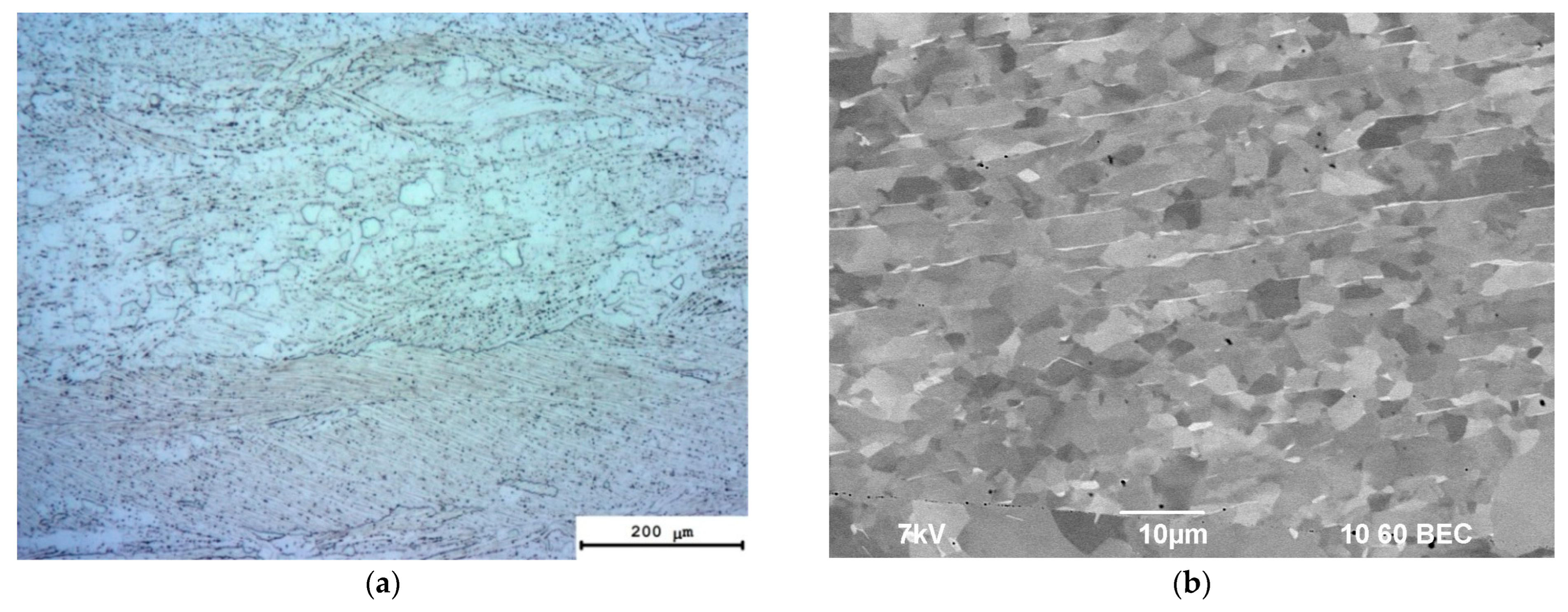
In the initial state, the microstructure of the Ti-5Al-2V coarse-grained alloy comprises a typical mixture of small elongated and large equiaxial grains of α-phases (Figure 3a). The mean sizes of the elongated α-phase grains are between 10 and 20 μm (Figure 3b), and the mean sizes of the equiaxial α-phase grains are between 50 and 100 μm (Figure 3a). At the grain boundaries (GBs) of the elongated α-phase, there are the elongated β-particles at ~10–15 μm long and less than 1 μm in thickness (Figure 3b). The volume fraction of the β-phase particles was small enough and was not detected by XRD phase analyses.
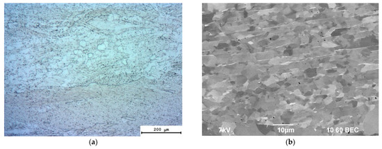
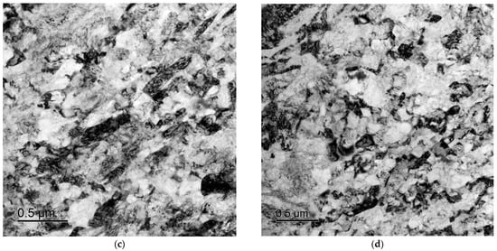
Figure 3.
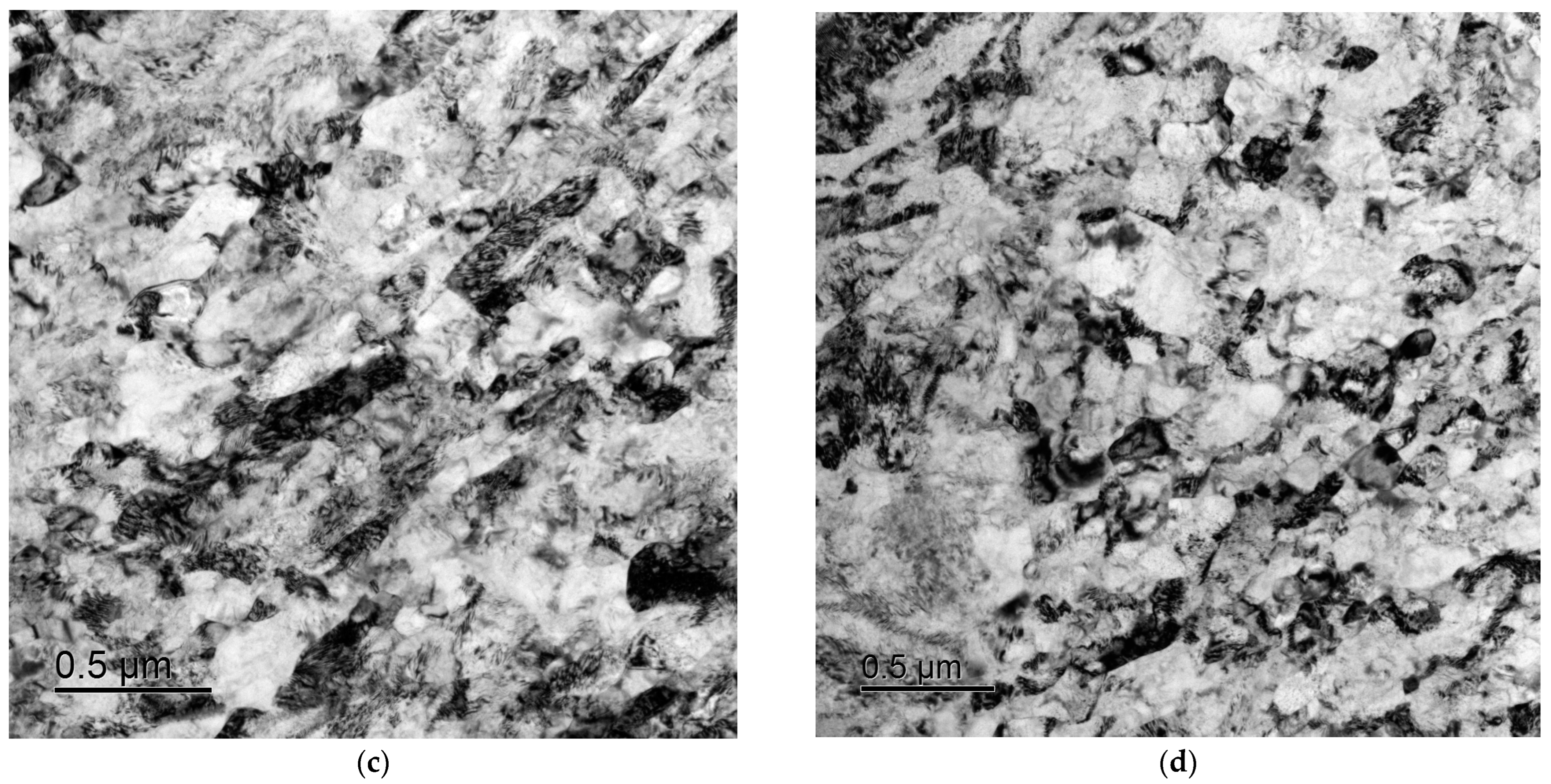
Microstructure in the coarse-grained (a,b) and UFG (c,d) alloy Ti-5Al-2V, reprinted with permission from [26,50]: (a) metallography; (b) SEM; (c,d) TEM.
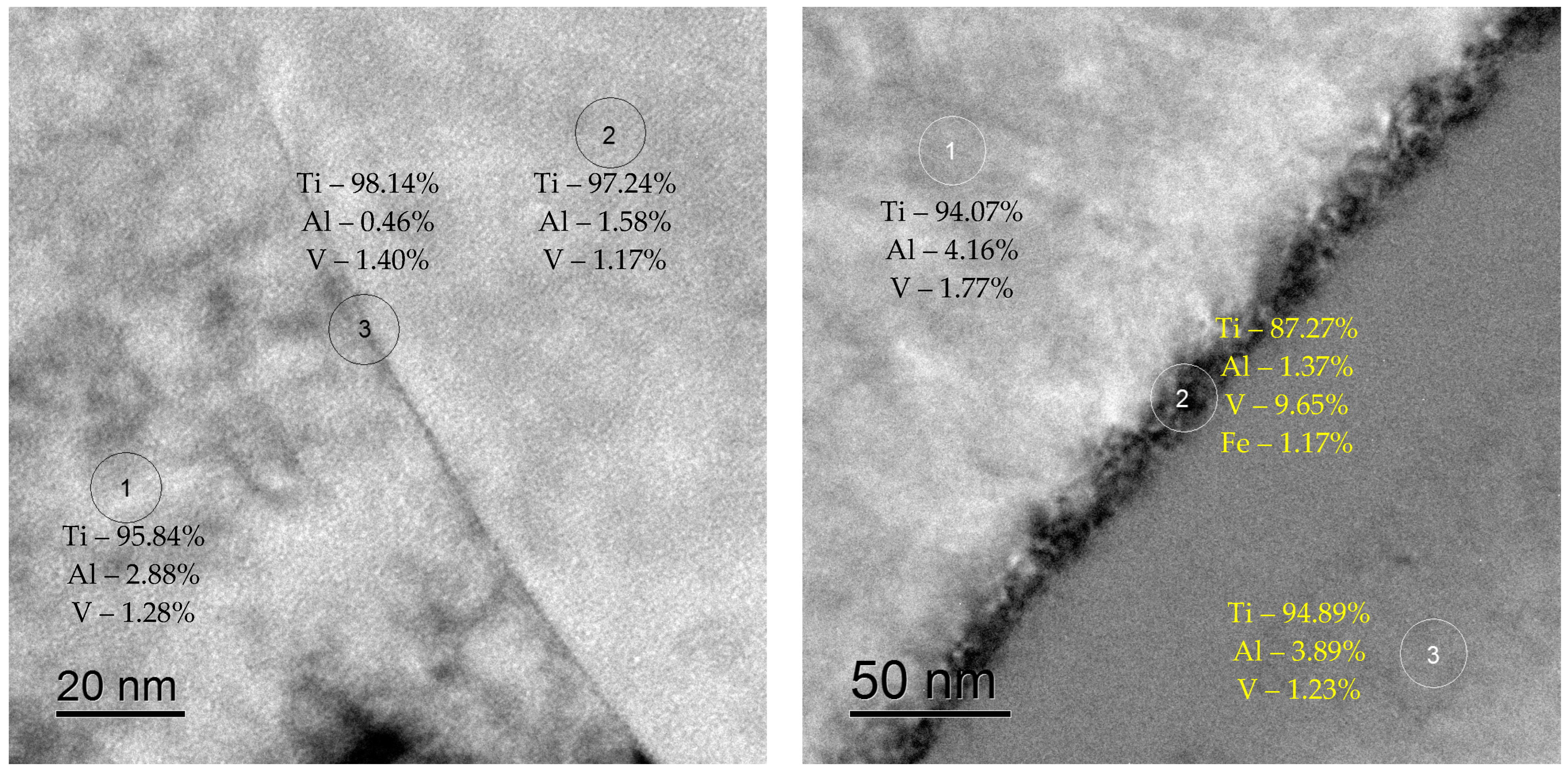
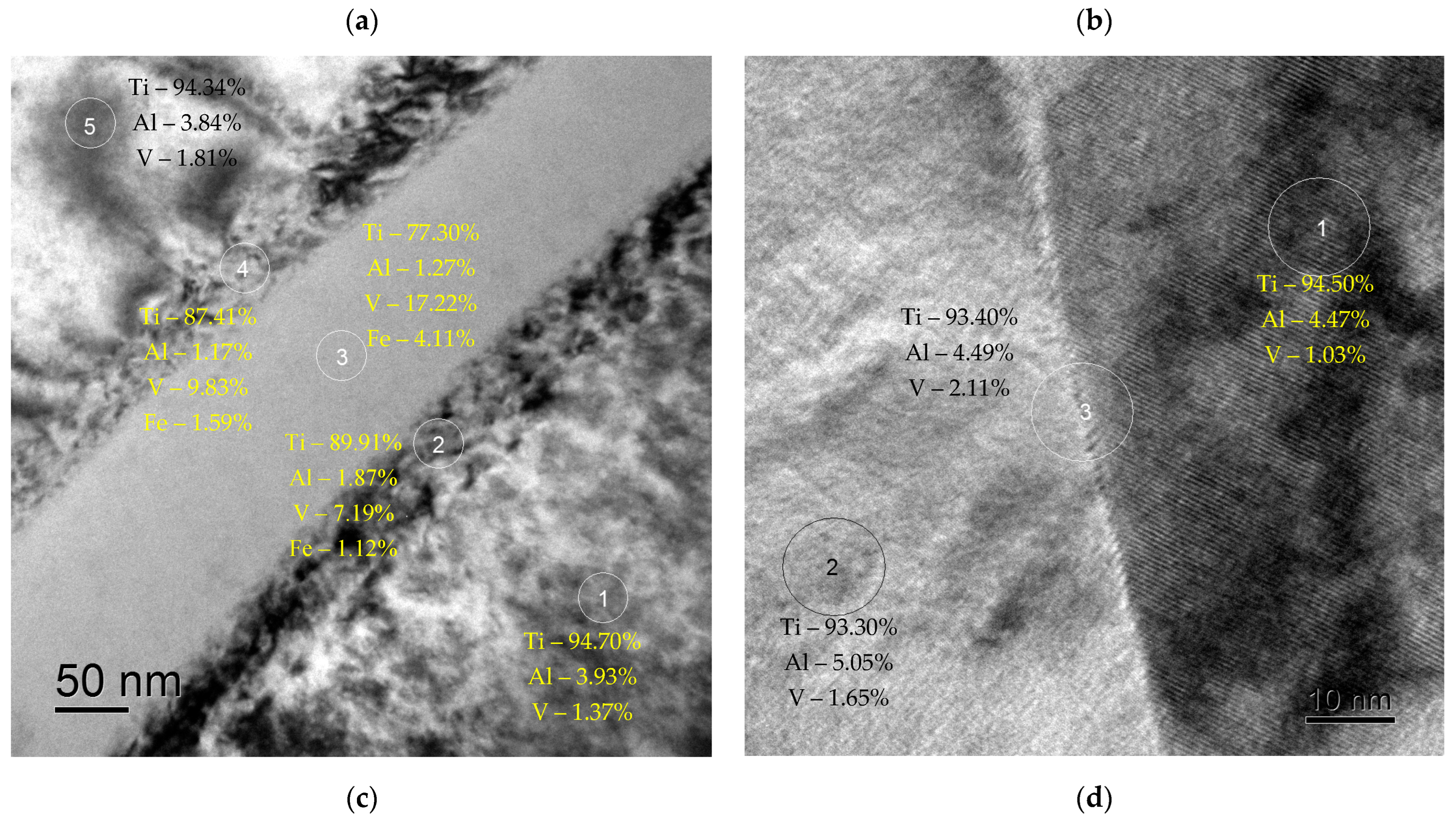
Two types of GBs were observed in the coarse-grained alloy Ti-5Al-2V. The GBs of the first type (~90–95 vol.%) are the pure ones, in which the grain boundary segregation of aluminum or vanadium is absent (Figure 4a, [26]). The averaged local Al concentration at such GBs was 3.8 ± 0.9 wt.% and the concentration of V was 1.9 ± 0.2 wt.% that differed from the concentrations of these elements in the crystal lattice insufficiently: the local concentration of Al in the GBs was 3.6 ± 0.9 wt.% and the local concentration of V was ~1.4 ± 0.2 wt.%. The GBs of the second type are the ones with the vanadium segregations, in which the local concentration of vanadium may achieve 10 wt.% (Figure 4b, [26]). The mean concentration of Al in the crystal lattice near the GBs of type II was ~4 wt.%, and the concentration of V was ~1.6 wt.%. Note that in the β-particles, the local concentration of V achieved 16–18%, and the concentration of Al was less than 1 wt.% (Figure 4c, [26]).
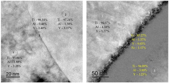
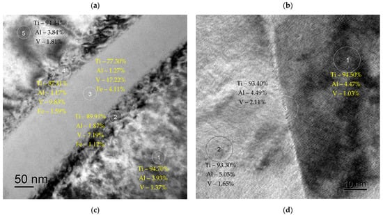
Figure 4.
EDS microanalysis of the grain boundary composition in the coarse-grained (a–c) and UFG (d) alloy Ti-5Al-2V, reprinted with permission from [26,50]. (a) GB of type I; (b) GB of type II; (c) β-particle in the GB of type II; (d) GB in the UFG alloy. TEM.
In the course of ECAP, a uniform grain microstructure with a mean grain size of 0.3–0.5 μm was formed (Figure 3c,d). The grains had an equiaxial shape. The grain boundary segregations of vanadium analogous to the ones observed in the coarse-grained alloy were not observed (Figure 4d, [26]). The mean concentration of Al at the GBs in the UFG alloy was ~3.2 ± 0.8 wt.%, and in the crystal lattice, it was ~4.0 ± 0.8 wt.%. The mean concentration of V at the GBs in the UFG alloy was ~1.9 ± 0.3 wt.%, and in the crystal lattice, it was ~1.5 ± 0.3 wt.%. The β-phase large particles at the GBs in the UFG alloy after ECAP were not observed. As it has been shown in [26], the decreasing of the local concentration of vanadium at the GBs as well as the absence of the β-phase particles are the origins of increased resistance of the UFG alloy Ti-5Al-2V to the intercrystalline hot salt corrosion (Table 2 and Table 3).

Table 2.
Parameters of microstructure and microhardness of the PT-3V alloy specimens after the diffusion welding.

Table 3.
Results of the corrosion testing of the welded joints of the PT-3V alloy.
3.2. Macrostructure of the Specimens after Diffusion Welding
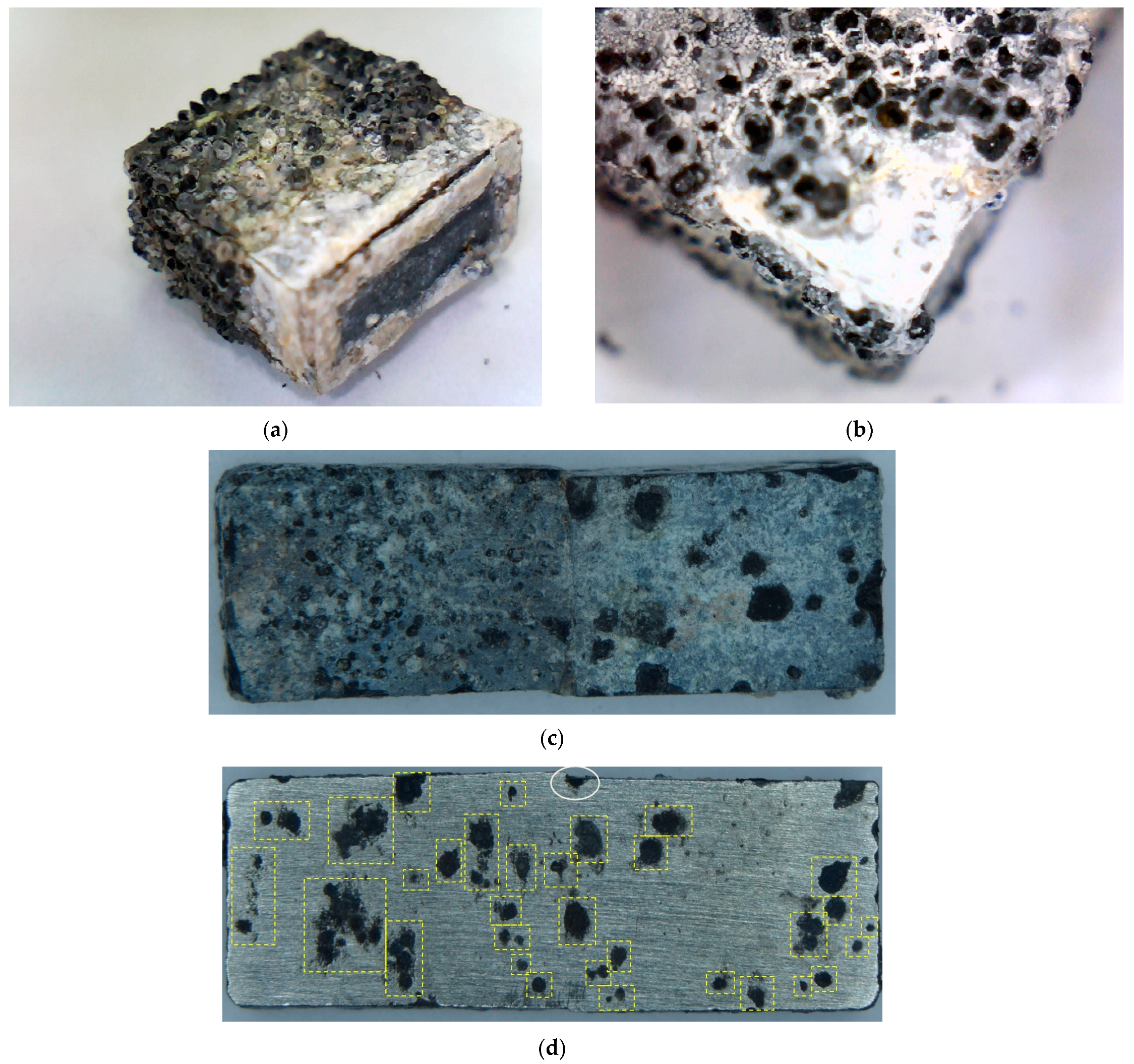
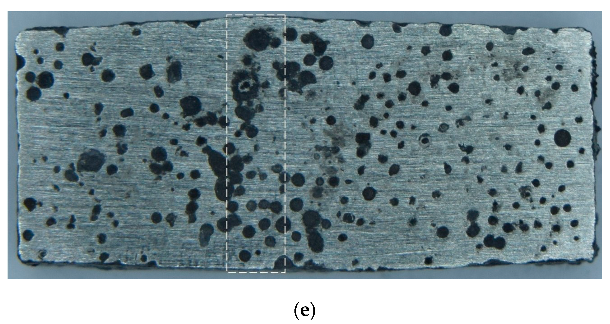
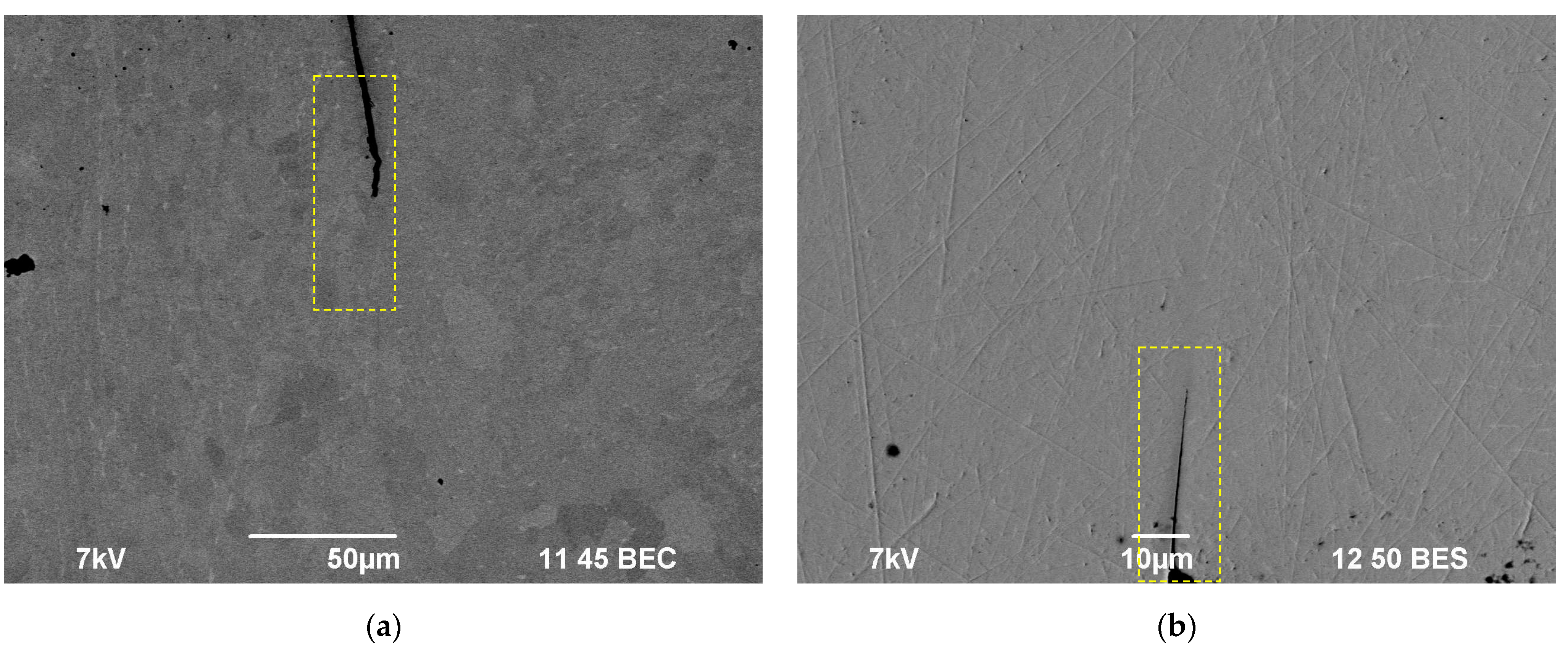
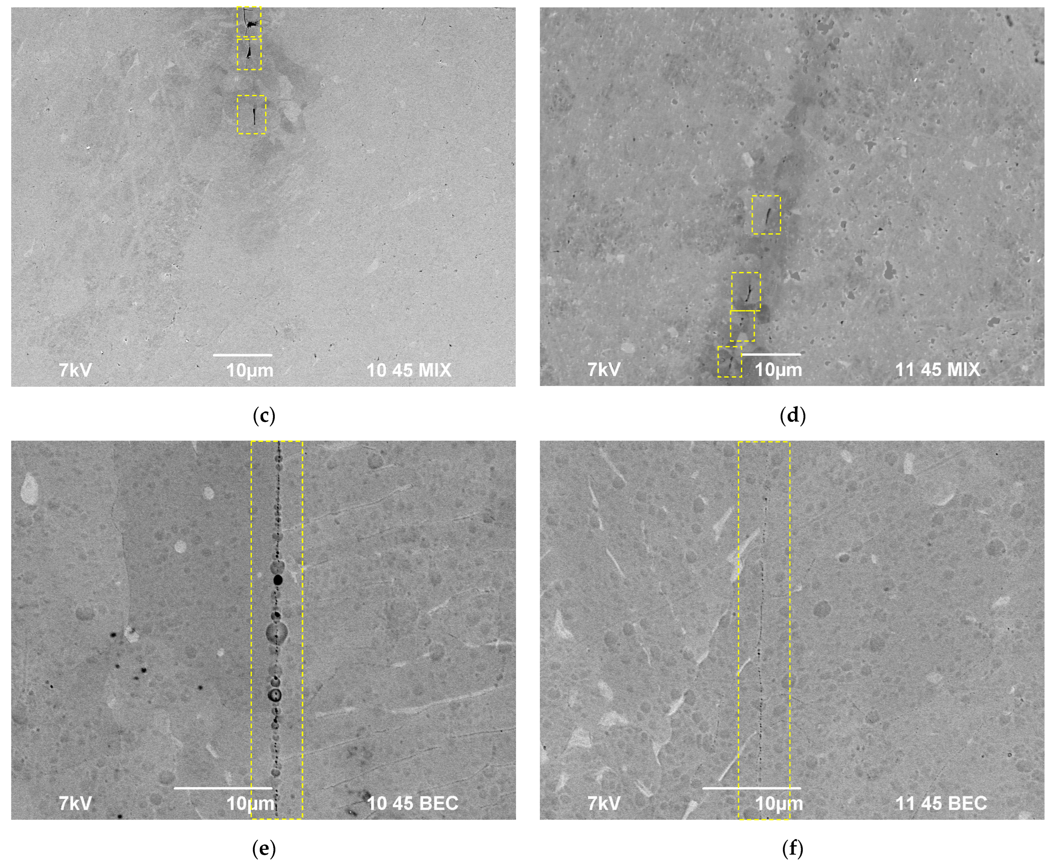
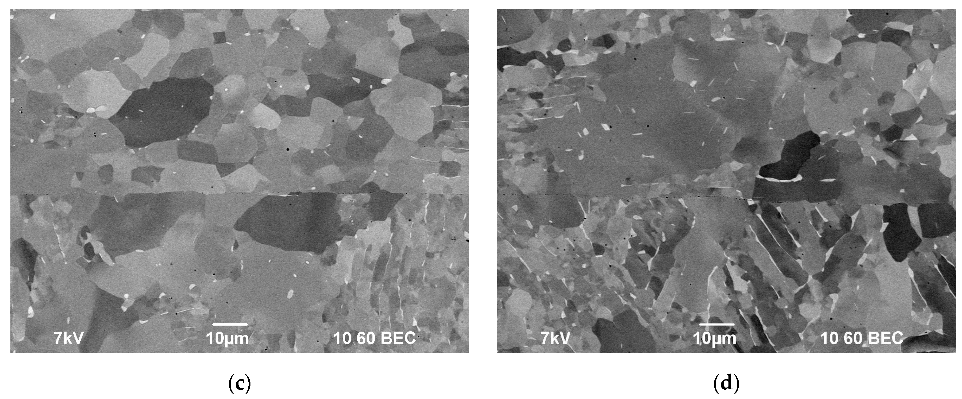
The incompletely welded joint areas (macrodefects) of ~50–70 μm are present at the edges of the coarse-grained specimens obtained by SPS at low stress, low temperatures, or increased heating rates (Figure 5d and Figure 6a; see Zone I in Figure 1c). Such macrodefects may promote crevice corrosion; therefore, the presence of these is undesirable. As a rule, large enough pores were located at the apices of the joint macrodefects. The volume fraction of the pores dropped with increasing distance from the specimen edges (i.e., from the maximum tensile strain area) abruptly. The length of the area with macropores depended on the welding regimes and ranged from 10 μm up to 100 μm (Figure 6c,e). In the rest (larger) area of the welded joints, there were micropores of the submicron sizes. The volume fraction of these depended on the diffusion welding regimes. Additionally, there were some individual macropores of ~1–2 mm in size (Figure 6e). Note that a small volume fraction of the macro- and micropores was observed in the case of the diffusion welding of the coarse-grained specimens in the interval of moderate temperatures (700–800 °C) and at low stresses (50 MPa) when the plastic deformation does not lead to the strain-induced pore formation yet.
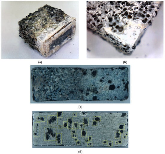
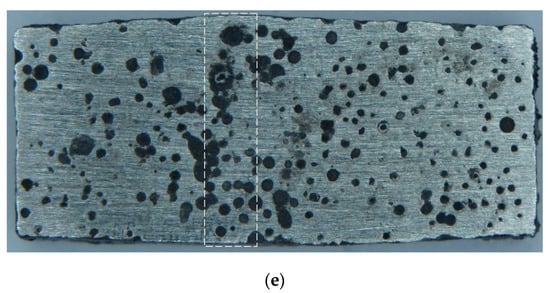
Figure 5.
Photographs of the alloy specimens after HSC testing (a,b), after rinsing in a hot water flow (c), and after mechanical polishing (d,e). In (d), the largest corrosion pits are highlighted by a yellow dashed line. The white solid line outlines a joint macrodefect, which the crevice corrosion and the pitting one go through simultaneously. In (e), the welded joint area (Zone I, see Figure 1c) is outlined by a white dashed line.
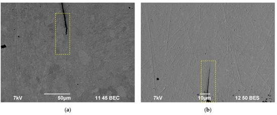
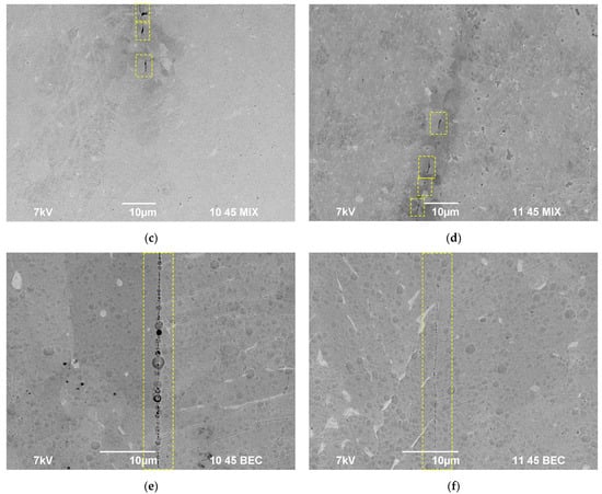
Figure 6.
Typical defects in the welded joints of the coarse-grained (a,c,e) and UFG (b,d,f) alloy after the diffusion welding (Vh = 50 °C/min, T = 800 °C, t = 10 min): (a,b) a joint defect, (c,d) a macropore, (e,f) a micropore. SEM.
In the specimens of the UFG titanium alloys, the macrodefects of joints were much smaller (Figure 6b). The volume fractions of the macro- and micropores in the welds of the UFG specimens were smaller than in the welds of the coarse-grained ones (Figure 6d,f and Figure 7); the large pores were observed preferentially in the case of the diffusion welding at low temperatures (600 °C) or at high stresses (70–100 MPa). In most cases, a highly dense microstructure is formed when welding the UFG specimens, in which the sizes and the volume fraction of the pores in Zone II (Figure 1c) are small (Figure 7). In the optimal welding regimes of the UFG specimens, the weld lines are hardly visible (Figure 7). It was caused by differences in the mechanisms of high-temperature deformation in SPS of the coarse-grained and UFG alloys as well as by the effect of accelerated diffusion delocalization of pores in the high-speed heating modes (for more details, see [50]).
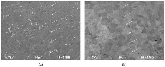
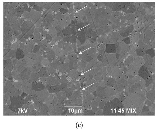
Figure 7.
Micropores in the welded joints of the UFG titanium alloy after diffusion welding (t = 10 min, P = 50 MPa): (a) Vh = 50 °C/min, T = 600 °C; (b) Vh = 350 °C/min, T = 700 °C; (c) Vh = 50 °C/min, T = 800 °C. SEM.
3.3. Microstructure of Specimens after Diffusion Welding
The varying of the main parameters of the diffusion welding does not affect the mean grain size of the coarse-grained alloy considerably (Table 2). The only exception was welding at the temperatures 1040 and 1140 °C exceeding the temperature of α↔β phase transition: the microstructure of the specimens obtained by diffusion welding at increased temperatures was featured by a martensite-type needle-like microstructure (see Figure 17 in [50]).
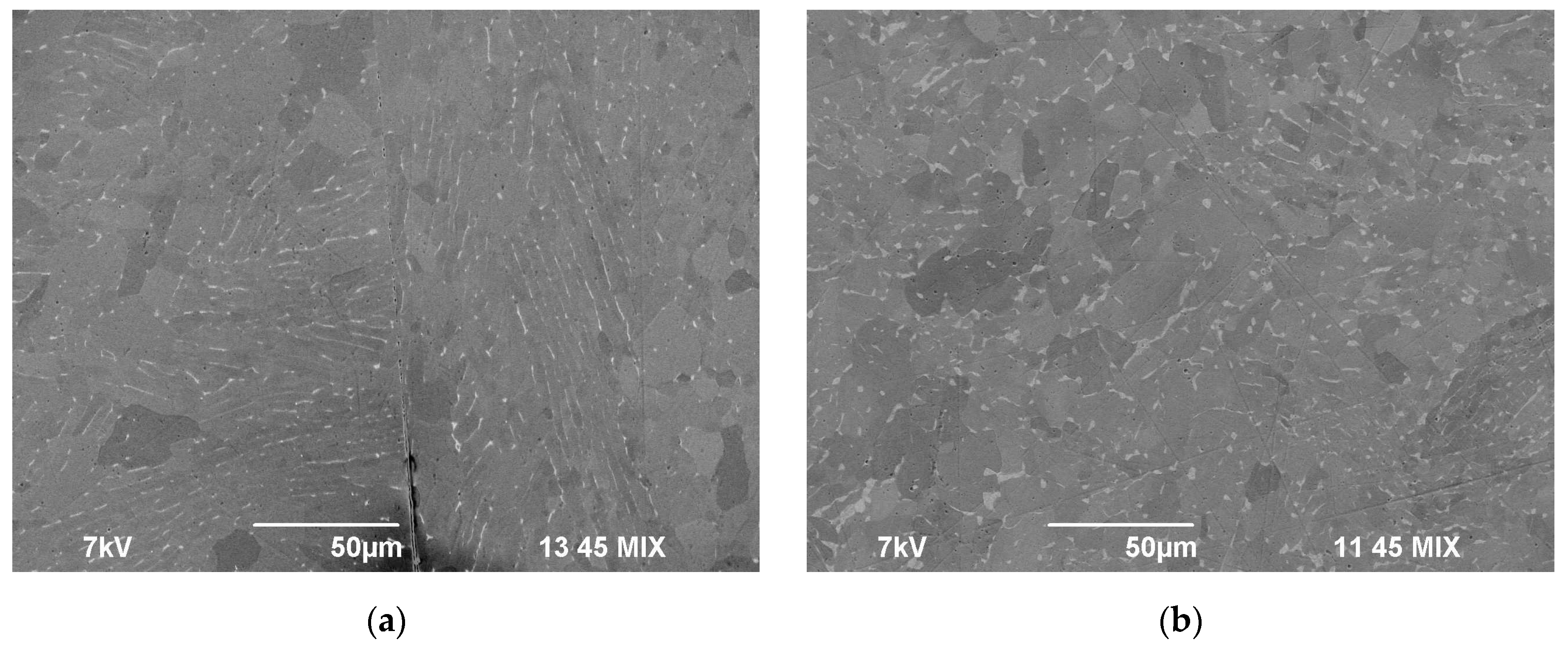
The alloy microstructure near the welded joint was featured by a coarse-grained mixed α-structure, and the nucleation of the β-particles was observed at the GBs (Figure 8). The most intensive nucleation of the β-particles was observed at the boundaries of the elongated α-grains, and the volume fraction of the β-particles at the boundaries of the equiaxial α-grains was low (Figure 8c,d). In the case of welding at reduced temperatures, the sizes and volume fraction of the β-particles in the coarse-grained welded joint material appeared to be close to the parameters of the β-particles in the initial state (Figure 3b and Figure 8a,c,d). Fast heating up to the temperatures corresponding to the two-phase (α + β) region (800 °C) and to the β-region (1030 °C) followed by cooling down to room temperature increased the sizes and the volume fraction of the β-particles (Figure 8b). The increase in the heating rate, the applied stress, and the isothermic holding time results in a decrease in the mean size of the β-phase elongated particles (Table 2, Figure 8b).
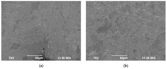
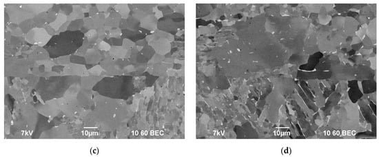
Figure 8.
Microstructure of the specimens of the coarse-grained alloy obtained in different regimes of the diffusion welding (P = 50 MPa, t = 10 min): (a) Vh = 50 °C/min, T = 600 °C; (b) Vh = 50 °C/min, T = 800 °C; (c) Vh = 100 °C/min, T = 700 °C; (d) Vh = 350 °C/min, T = 700 °C. SEM.
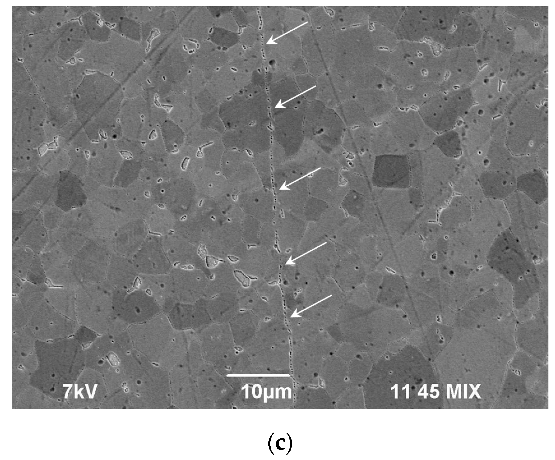
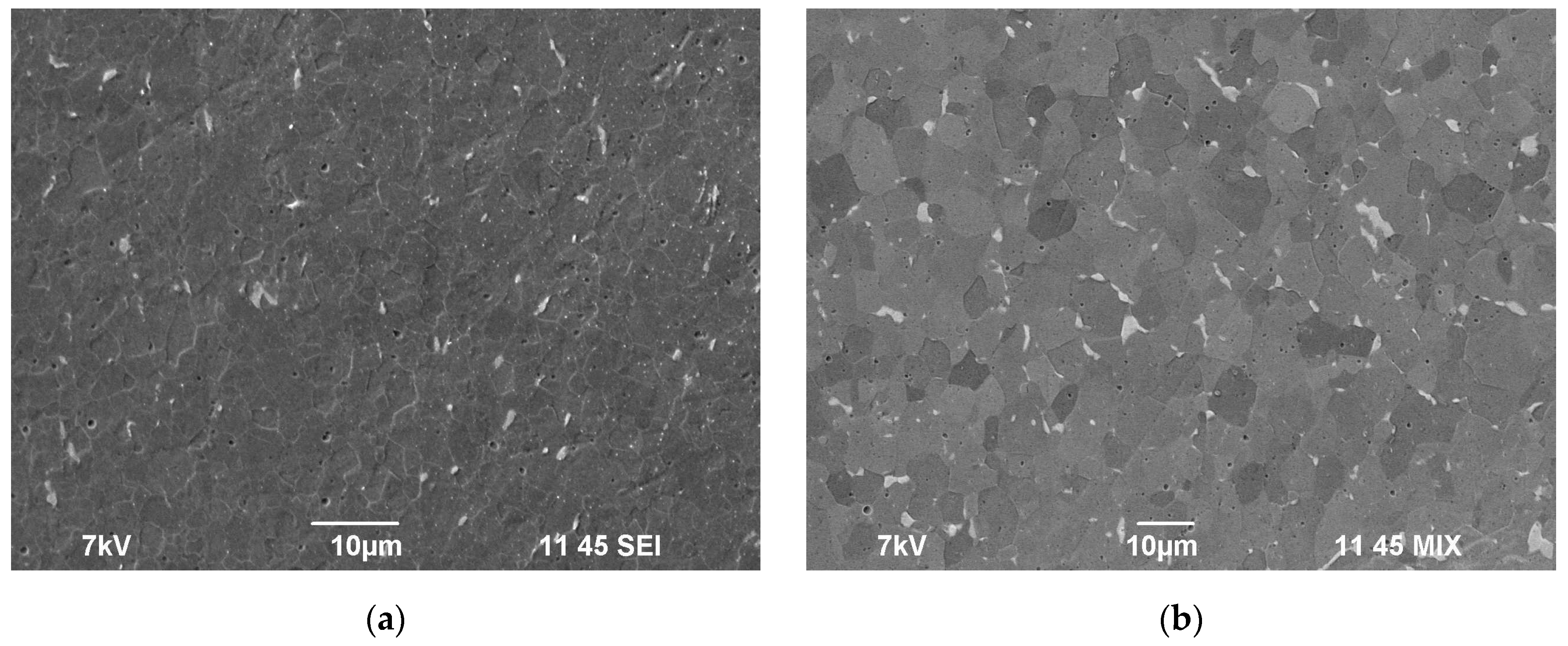
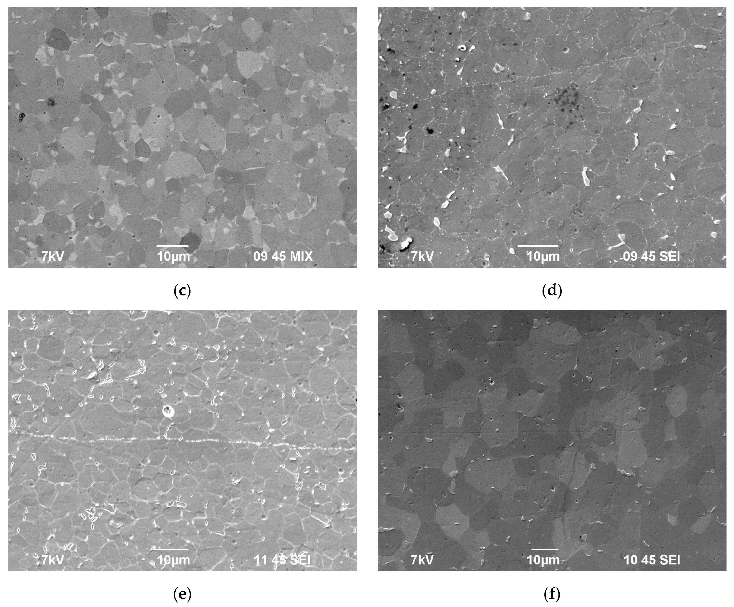
The parameters of the microstructure of the UFG welded specimens are presented in Figure 9 and in Table 2. The metallographic and SEM investigations of the welded joints in the specimens of the UFG alloys demonstrated an increase in the welding temperature from 600 to 800 °C (at Vh = 50 °C/min, P = 50 MPa, t = 10 min), thereby increasing the dα from 4.8 up to 6.9 μm (see Figure 17 in [50]). The mean grain size dα in the welded joints of the UFG specimens appeared to be 1.5–3 times less than the mean grain size in the welded joints of the coarse-grained specimens (Figure 9). There were some individual β-particles at the GBs, the sizes of which were 2–3 μm (Figure 9a,b,d,e). An increase in the welding temperature and in the holding time (at T = 700 °C) results in an increase in the β-particle size dβ and in the sizes of the titanium alloy grains dα (Table 2). An increase in the heating rate from 10 to 350 °C/min did not affect the β-grain sizes considerably but decreased the mean titanium alloy grain sizes (Table 2).
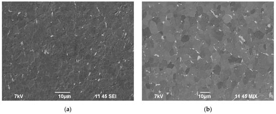
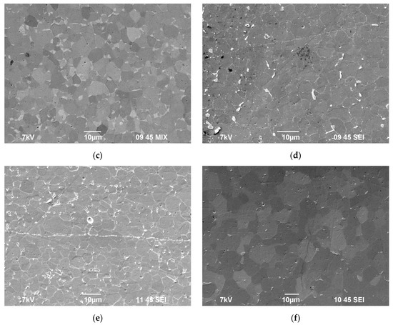
Figure 9.
Microstructure of the UFG specimens obtained in different diffusion welding regimes (P = 50 MPa): (a) Vh = 50 °C/min, T = 600 °C, t = 10 min; (b) Vh = 50 °C/min, T = 700 °C, t = 10 min; (c) Vh = 50 °C/min, T = 800 °C, t = 10 min; (d) Vh = 100 °C/min, T = 700 °C, t = 10 min; (e) Vh = 350 °C/min, T = 700 °C, t = 10 min; (f) Vh = 50 °C/min, T = 700 °C, t = 90 min. SEM.
3.4. Hot Salt Corrosion Test
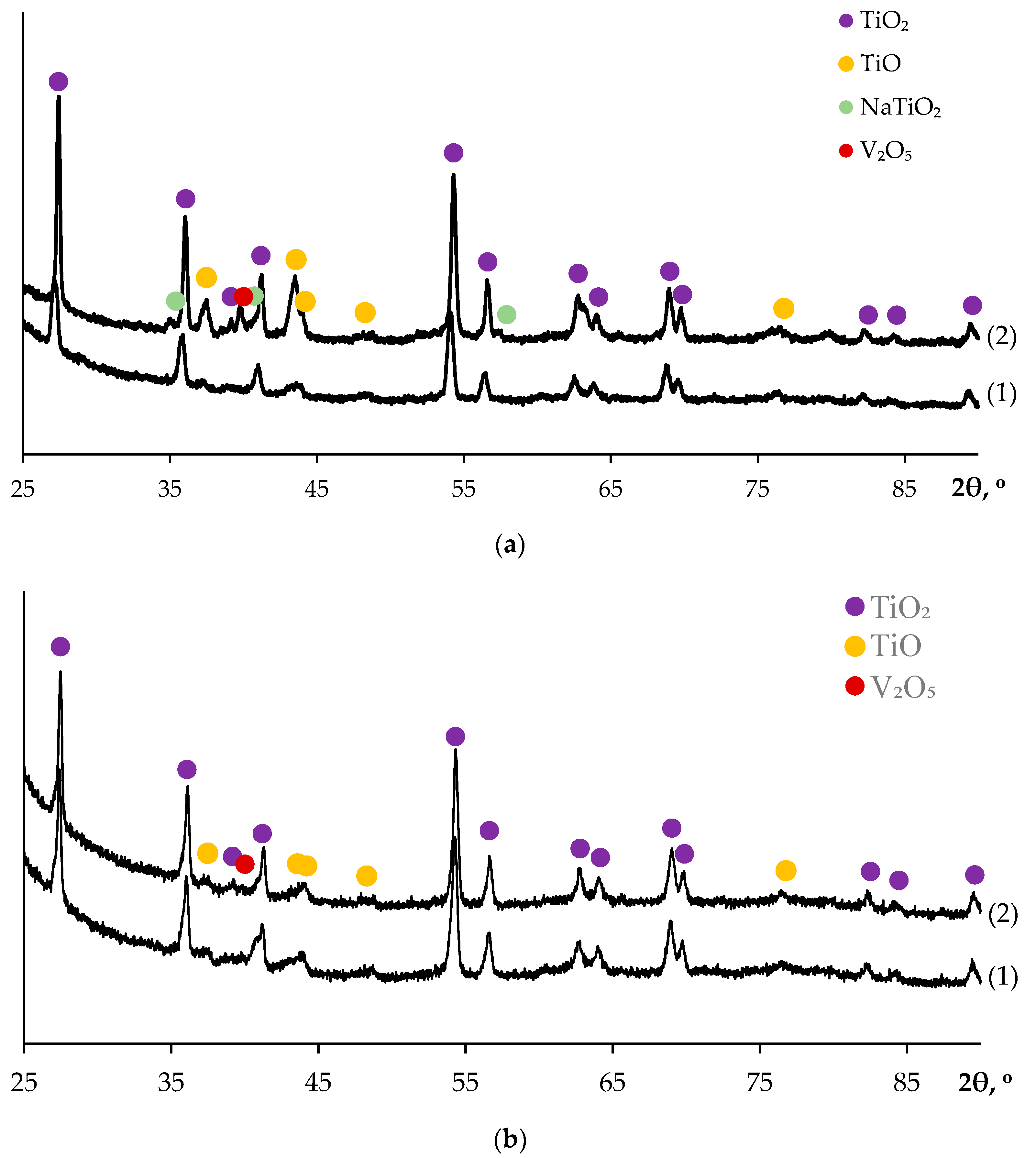
Photographs of the specimens after the HSC testing are presented in Figure 5. A porous character of the salt contamination (Figure 5a,b) evidences the formation of gaseous TiCl4 in the course of the HSC (see [54]). The XRD phase analysis demonstrated the presence of rutile phase TiO2, Na4Ti5O12, and NaCl on the surface of the coarse-grained and UFG specimens alloys (Figure 10).
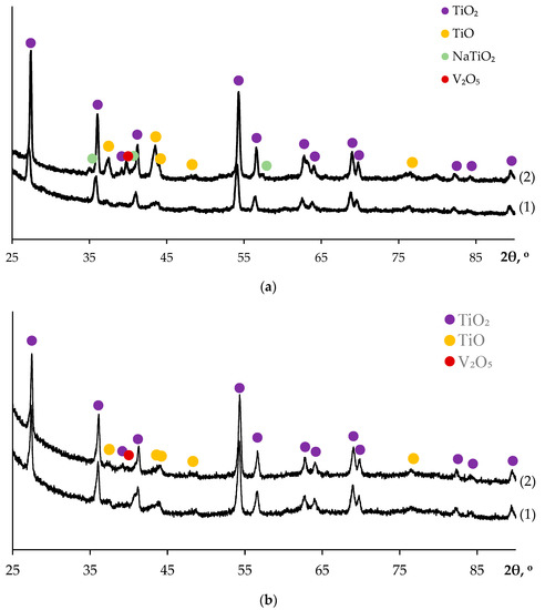
Figure 10.
Results of XRD analysis of the corrosion products on the surfaces of the specimens of coarse-grained (a) and UFG (b) alloys after HSC testing. The numbers (1) and (2) in (a,b) correspond to samples #1 and #2 (see Figure 1b,c).
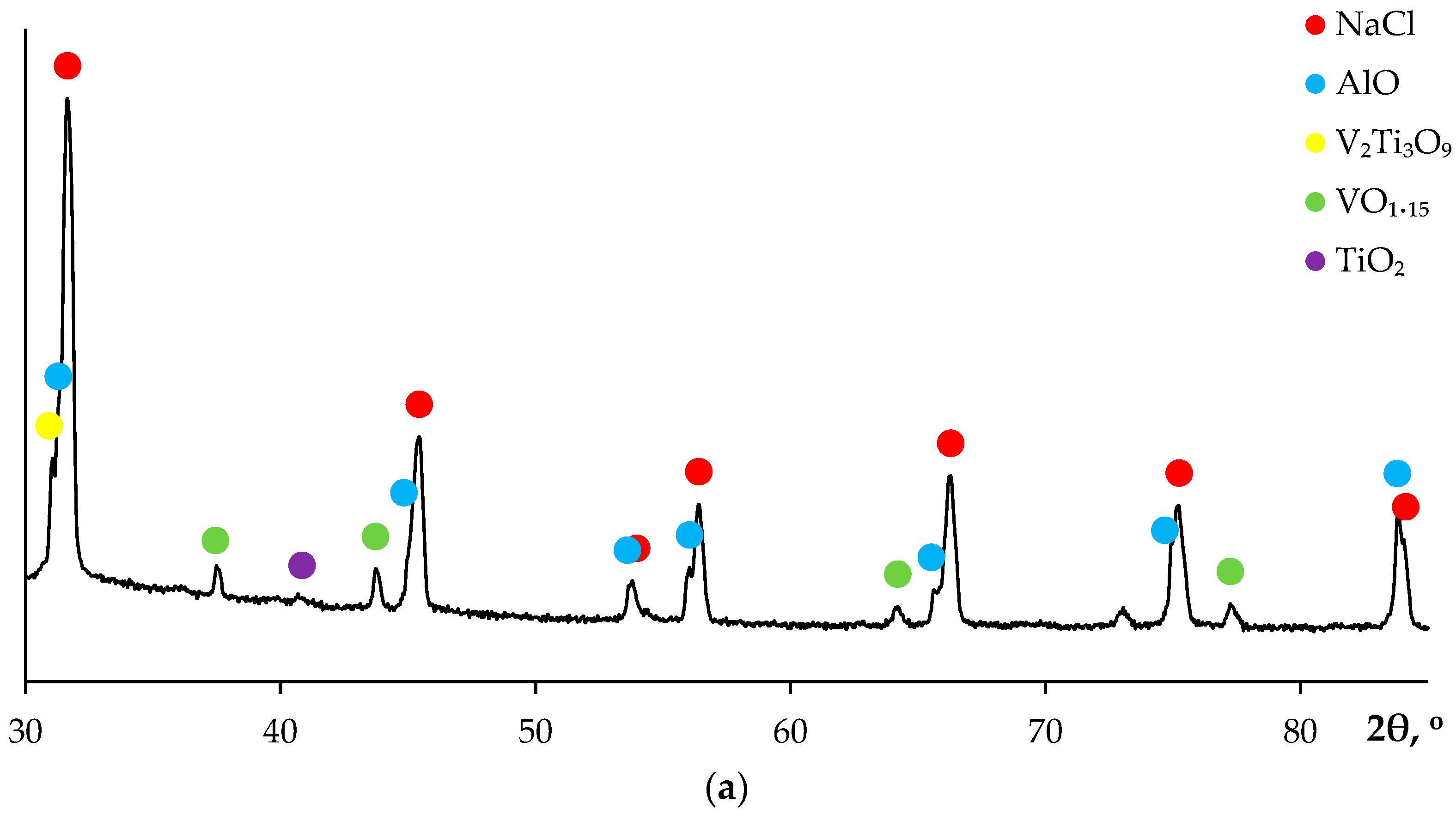
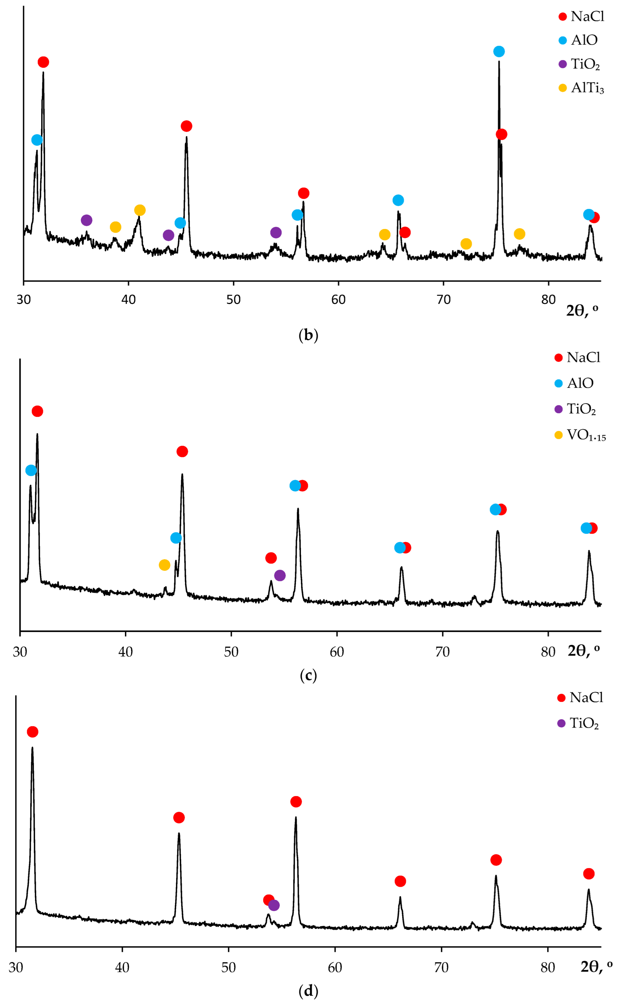
The salt contaminations on the specimen surfaces are the mixtures of NaCl (ICDD 00-005-0628), titanium oxides TiO2 (ICDD 00-015-0875) and TiO (ICDD 01-072-0020), and alumina (ICDD 01-075-0278) as well as of the vanadium-based phases—VO1.15 (ICDD 01-073-9519), V2Ti3O9 (ICDD 00-030-1429), and Al3V (ICDD 01-079-5717) (Figure 11). The salt contaminations on the samples obtained at temperatures greater than 1000 °C also consisted of NaCl, TiO2, TiO, and alumina but instead of the vanadium-based phases, the aluminum-containing phases (TiAl2Cl8 (ICDD 01-076-1072), compound AlTi3 (ICDD 00-052-0859)), as well as traces of VO2 (ICDD 03-065-7960), were observed (Figure 11).
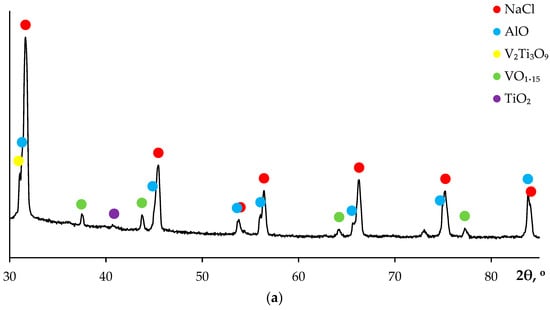
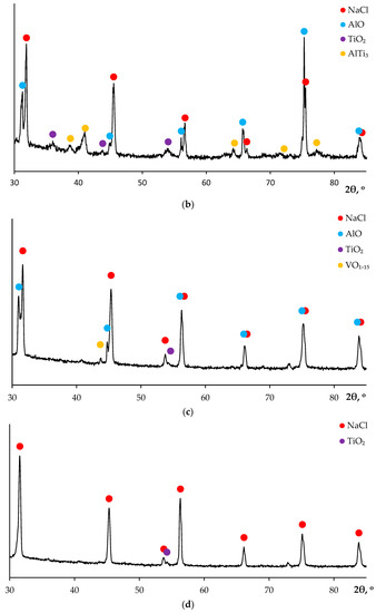
Figure 11.
Results of XRD analysis of the salt contaminations on the surfaces of coarse-grained (a,b) and UFG (c,d) specimens after HSC testing: (a,c) Vh = 50 °C/min, T = 600 °C, t = 10 min, P = 50 MPa; (b) Vh = 50 °C/min, T = 1030 °C, t = 10 min, P = 50 MPa; (d) Vh = 50 °C/min, T = 1140 °C, t = 10 min, P = 50 MPa.
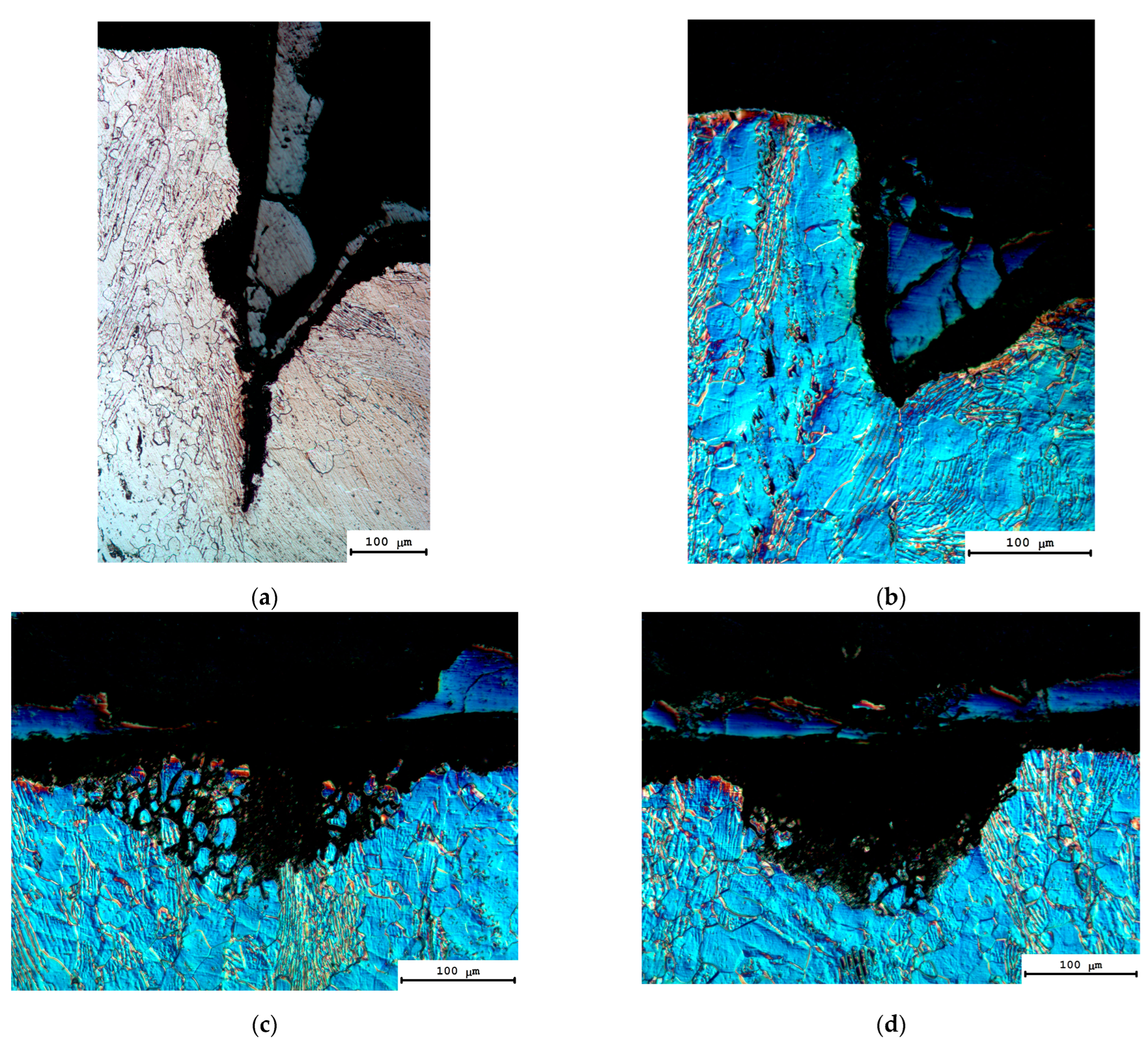
The results of an investigation of the macrostructure of the welded joint cross-sections demonstrated the mechanisms of corrosion destruction of the metal in the welded joint areas and far away from the different joint areas (Table 3, Figure 12).
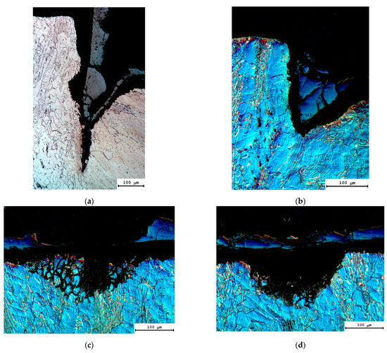
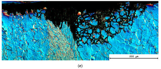
Figure 12.
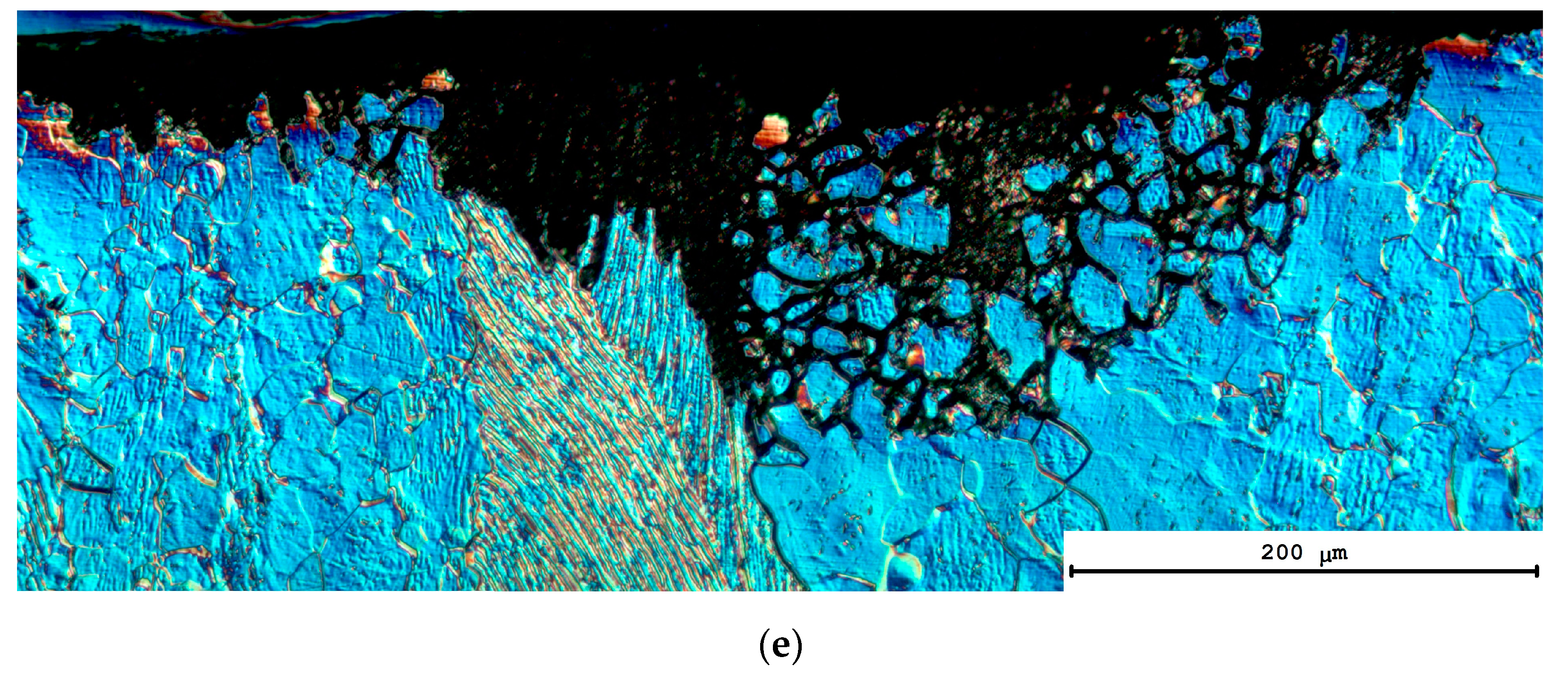
Corrosion defects on the surfaces of the coarse-grained specimens after HSC testing: (a,b) crevice corrosion in Zone I; (c,d) pitting corrosion in Zone II, (e) IGC in Zone II. Zones I and II are denoted in accordance with Figure 1c. Metallography.
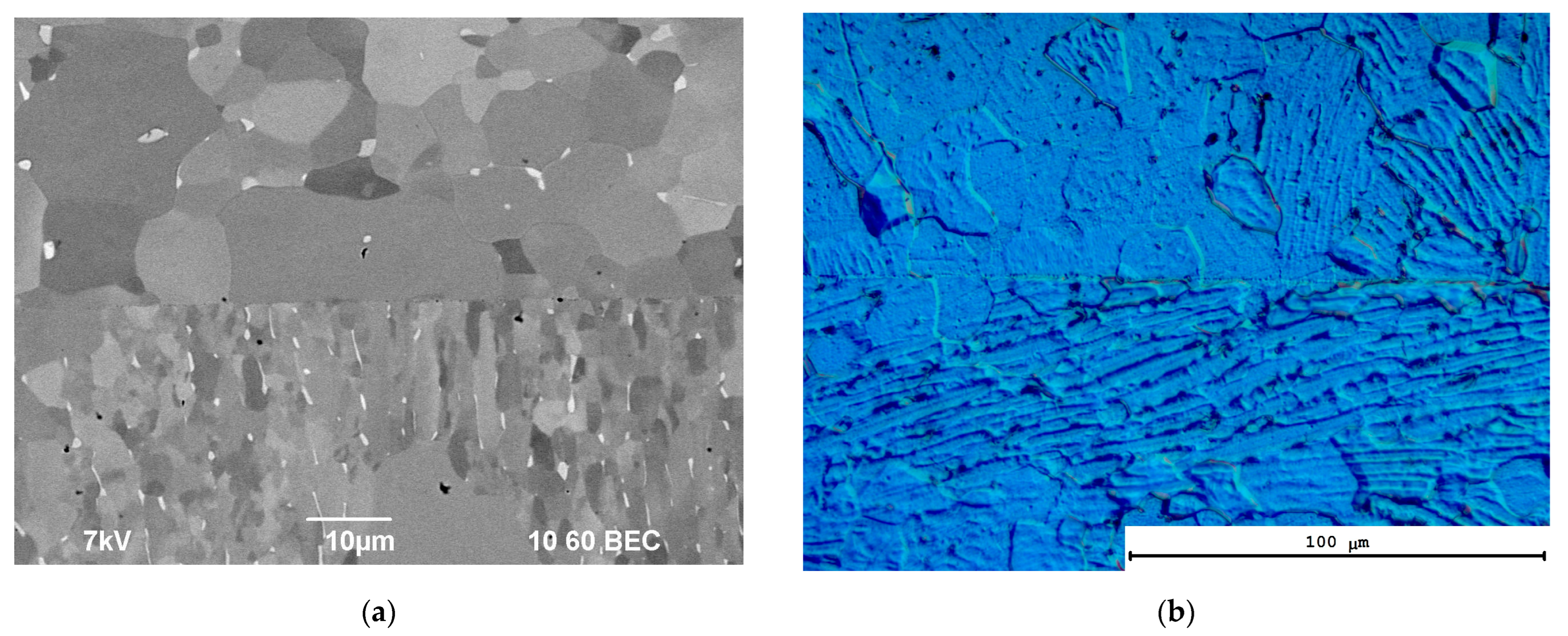
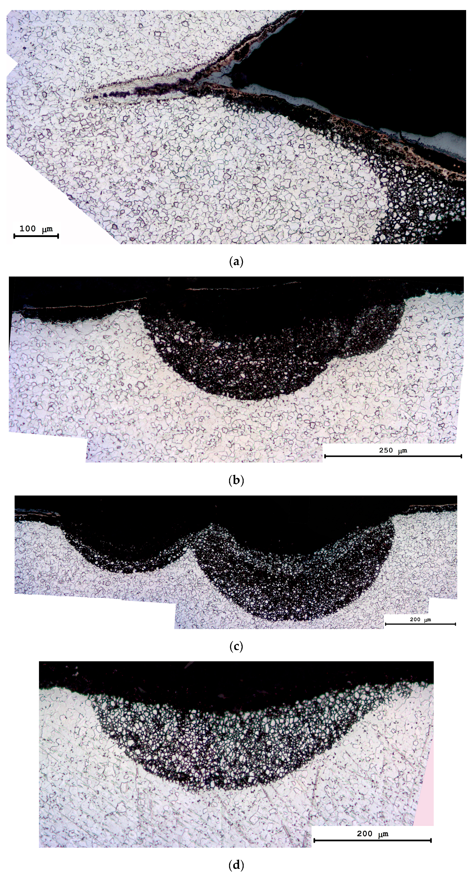
The metallographic investigations of the character of the corrosion damage of the coarse-grained specimen demonstrated a combination of pitting corrosion and the crevice to take place in the welded joint area (Figure 12a,b). The depth of the crevice corrosion defects along the welded joints is determined by the porosity of the joints directly. In the case of highly porous joints obtained in non-optimal regimes of diffusion welding, the depth of corrosion defects may exceed 300 μm. The intensity of the pitting corrosion in the welded joint area depends on the nonuniformity of the microstructure of the coarse-grained alloy in the welded joint area. The areas with essentially different microstructure parameters may appear at different sides of the welded joints of the coarse-grained area that has been observed (Figure 13). This factor leads to a nonuniform distribution of large corrosion pits at different sides of the joint line and an increased uncertainty of measurements of the mean depth of the corrosion defects (up to 30% of hav, see Table 3). The same factor causes possible nonuniformity of the corrosion of the welded joints. As one can see in Figure 12a,b, the corrosion intensity at one side of the welded joint may differ from the one on another side.
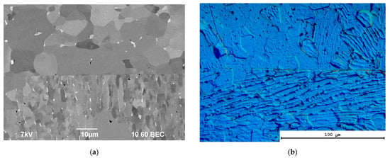
Figure 13.
Nonuniformity of the metal microstructure in the weld joint area of the coarse-grained titanium alloy: (a) SEM; (b) Metallography.
Outside of the welded joints of the coarse-grained alloys, a combination of intercrystalline corrosion and pitting corrosion takes place. The largest corrosion pits were distributed uniformly over the whole specimen area (Figure 12c–e and Figure 14). It should be stressed here that the most intensive corrosion fracture was observed in the area of the elongated α-grains with increased volume fraction of the β-particles (Figure 12c and Figure 14c,d). Note also that the regions of the plate-wise α-grains in the coarse-grained specimens were distributed nonuniformly (Figure 3a). This causes a nonuniform character of the corrosion defect distribution over the metal surface.
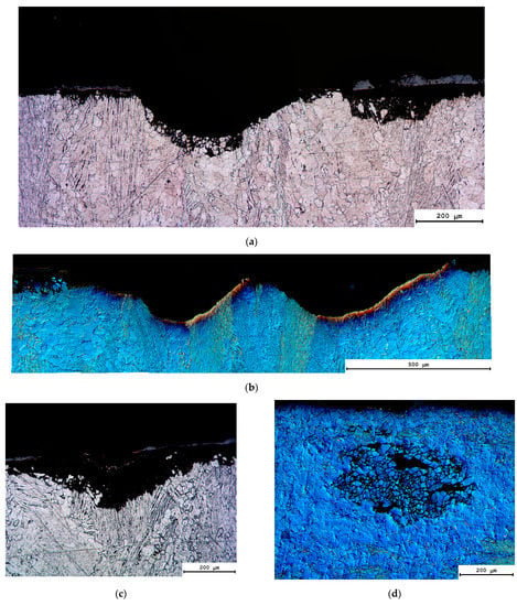
Figure 14.
The nonuniform distribution of large corrosion pits at different sides of the joint line of the coarse-grained alloy after HSC testing: (a) Vh = 100 °C/min, t = 700 °C, t = 10 min, P = 50 MPa; (b) Vh = 100 °C/min, t = 700 °C, t = 10 min, P = 100 MPa. Examples of defect formation in the plate-wise α-phase regions are presented in (c,d). Metallography.
The analysis of the character of the corrosion destruction has shown that intercrystalline corrosion takes place at the initial stage. This, in our opinion, is confirmed by the presence of small ICC areas on the specimen surfaces without the formation of large corrosion pits (Figure 14d). However, later the ICC defects transform into large corrosion pits defects (Figure 14a,b). The size of the corrosion pits may achieve several hundred microns and may be close to the typical size of the elongated α-grain areas (Figure 3a). This suggests that the hot salt corrosion of the coarse-grained specimens has a two-stage character. In the first stage, the ICC in the fine-grained elongated α-grain areas takes place and then the pitting or uniform corrosion at the equiaxial α-grain areas (the boundaries which are practically free of the β-phase inclusions) occurs.
The applied stress and the holding time affect the depth of the corrosion defects in the welded joints of the coarse-grained specimens, which are the most essential. As one can see from Table 3, the increasing of the holding time from 0 up to 90 min (at T = 700 °C, P = 50 MPa) results in a reduction in the corrosion defect depth from 211 ± 42 μm to 125 ± 53 μm. The maximum corrosion defect depth decreased from 390 μm down to 163 μm. Note that the depth of the corrosion defects varied in a large enough range that results in a large magnitude of the root-mean-square deviation (i.e., a large uncertainty in determining the mean depth of the corrosion defects). As noted above, this is due to the scatter of the sizes of the plate-wise α-phase regions (Figure 3a) as well as to the cases when the alloys’ microstructure is different at different sides of the weld joints (Figure 13).
Note also that despite the observed differences in the corrosion resistance of the specimens obtained in different regimes of diffusion welding, in general, the sizes of the corrosion defects appeared to be lower than in the alloy in the initial state (before the diffusion welding) (Table 3).
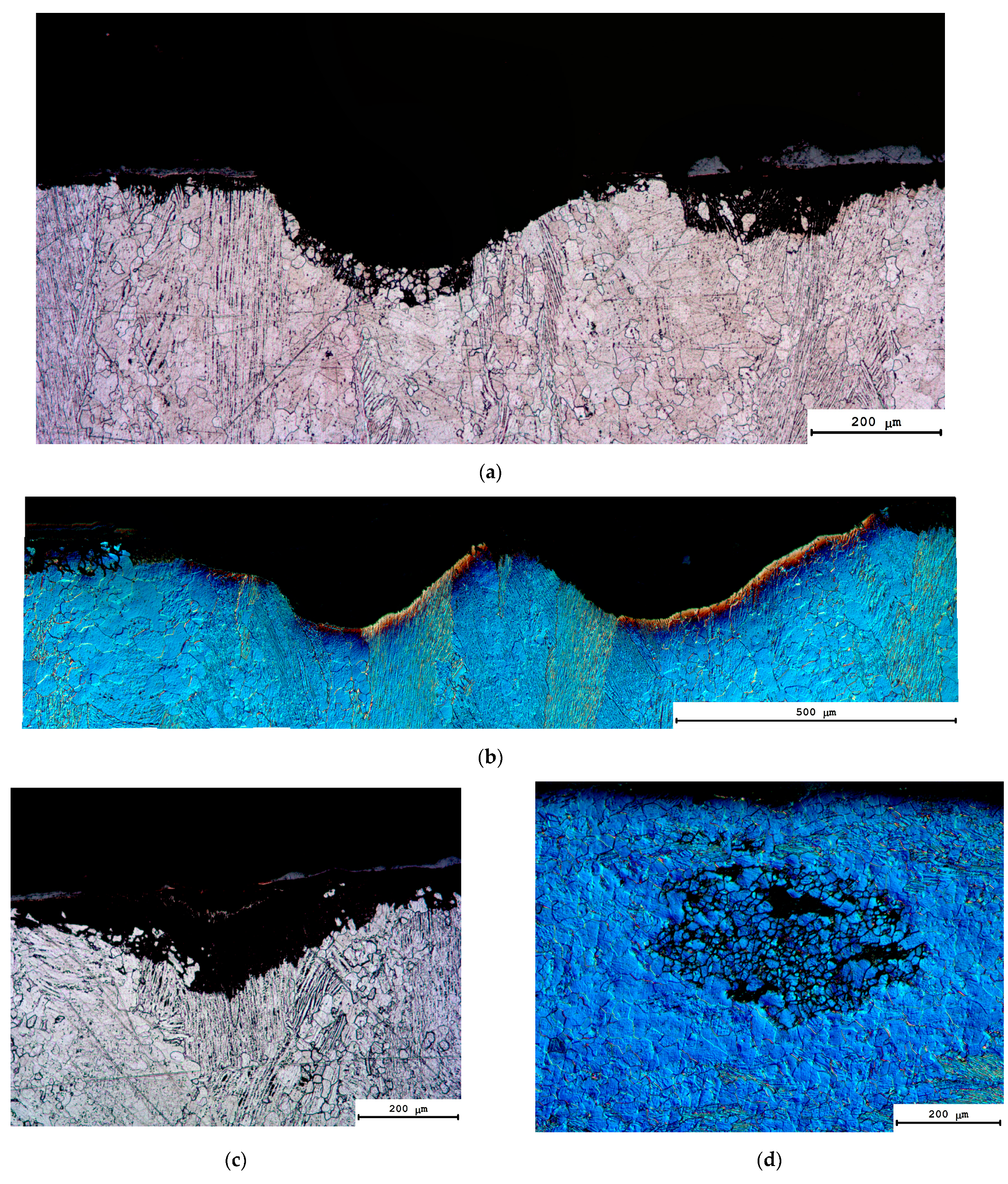
In the case of the UFG alloys, a similar situation takes place—the crevice corrosion was observed in the case of testing the welded joints with increased porosity only (Table 3, Figure 15a). Outside the welded joints, simultaneous ICC and pitting corrosion were observed (Figure 15b–d), as in the coarse-grained specimens. One can see in Figure 15a how the crevice corrosion region of the welded joint transforms into the ICC one near the weld. The ICC defects and the corrosion pits were distributed nonuniformly on the surface of the welded fine-grained specimen (Figure 15b,c). At present, the origin of the nonuniform distribution of the corrosion defects in the UFG specimens is still unclear. We could not relate it unambiguously to the peculiarities of the structure of UFG specimens or the HSC testing technique.
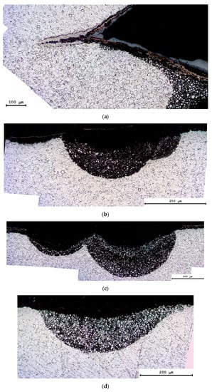
Figure 15.
Corrosion defects on the surface of the UFG specimens after HSC testing: (a) Vh = 100 °C/min, T = 700 °C, t = 0 min, P = 50 MPa, (b) Vh = 100 °C/min, T = 600 °C, t = 10 min, P = 50 MPa, (c) Vh = 100 °C/min, t = 800 °C, t = 10 min, P = 50 MPa, (d) Vh = 100 °C/min, t = 700 °C, t = 10 min, P = 50 MPa. Metallography.
Note also that the increase in the holding time and the diffusion welding temperature resulted in an increase in the corrosion defect depth in the welded joints of the UFG specimens (Table 3). In the case of low welding temperatures, low heating rates, and low stress, the depth of corrosion defects appeared to be small enough and did not exceed the depths of the ICC defects in the UFG alloy after ECAP (Table 3). The welding regime in the range of moderate heating temperatures (700 °C, corresponding to the two-phase (α + β) region boundary) at small stress (70 MPa), and the heating rate 10 °C/min when the mean depth of the corrosion defects was ~110–130 μm and the large joint defects were absent is the optimal one. It should be stressed here that, in these regimes, the mean pit depth in the UFG specimens appeared to be 1.5–2 times smaller than the depth of the corrosion pits in the coarse-grained specimens (Table 3). So far, one can conclude the welded joints of the UFG alloys have a higher corrosion resistance compared to the welded joints of the coarse-grained metals.
The summary of the results of the HSC testing shows that the increase in the welding temperature resulted in an increase in the mean corrosion defect depth (hav) and the maximum ones (hmax). Increasing the welding temperature from 600 to 800 °C resulted in an increase in the hav from 124 ± 34 μm to 285 ± 59 μm, and the hmax increased from 188 μm up to 400–420 μm (Table 3). The increasing of the heating rate from 50 up to 350 °C/min resulted in a reduction in the hav from 304 ± 51 μm down to 189 ± 36 μm. Increasing the stress decreases hav and hmax in the welded joints of the UFG alloys. The magnitude of the holding time (t) did not affect the mean size of the corrosion defects in the HSC testing of the UFG specimens (Table 3).
3.5. Electrochemical Corrosion Test
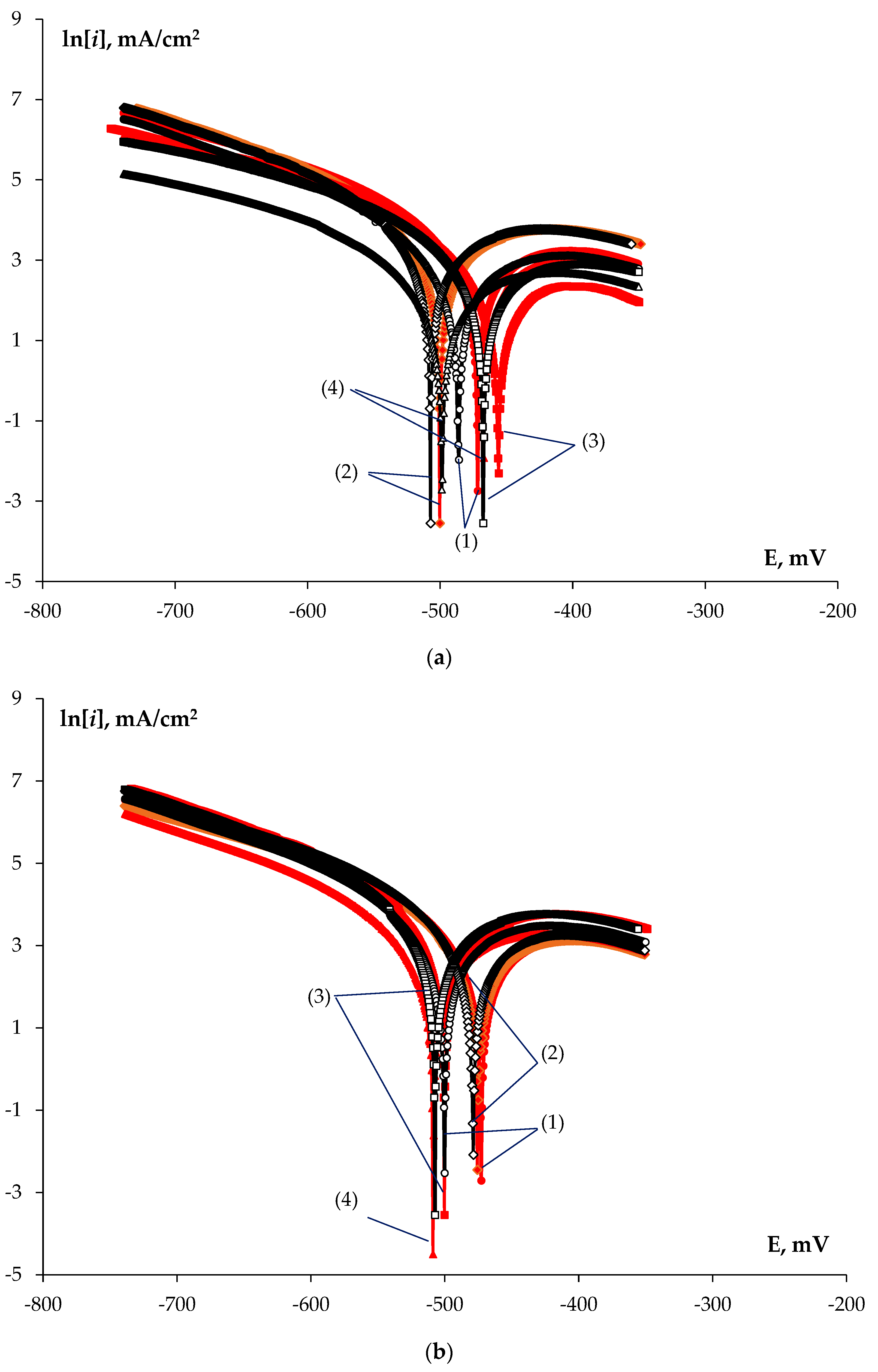
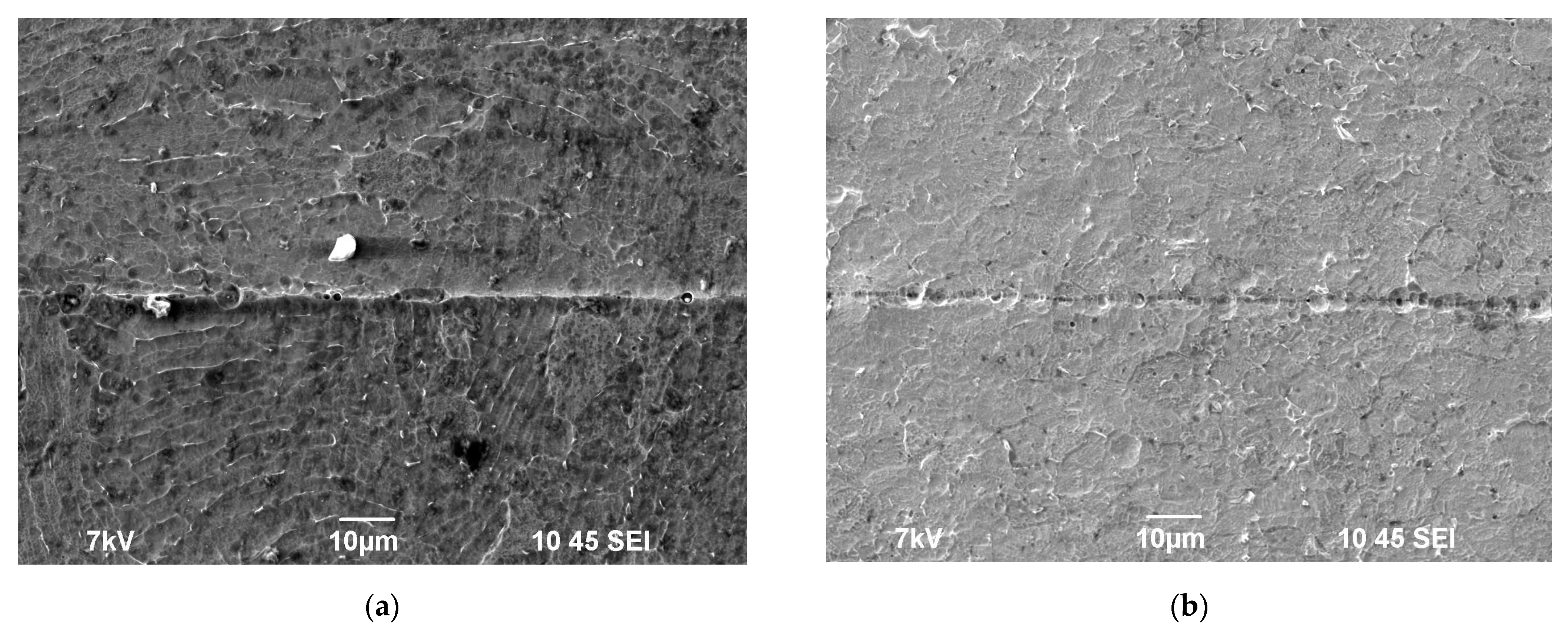
Now let us analyze the results of the electrochemical investigations of the corrosion resistance of the welded joints presented in Table 3. Tafel curves ln[i] – E had a conventional form (Figure 16). First, note that the testing was performed in 10%HNO3 + 0.2%HF aqueous solutions, promoting, first of all, the corrosive destruction of the GBs and the interphase boundaries in the α-titanium alloys [67]. As an example, the SEM images of the welded joint specimens after the electrochemical testing are presented in Figure 17. As one can see in Figure 17, the electrochemical testing resulted in an intense etching of the interphase boundaries near the β-particles. When studying the microstructure by SEM in the Z-regime (the atomic number contrast) and MIX-regime, the β-particles had a brighter color due to increased concentration of the alloying elements in these (first vanadium) [26,50]. One can see also that very intensive corrosion etching of the welded joints takes place in the course of the electrochemical testing areas with increased porosity.
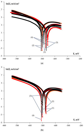
Figure 16.
Results of the electrochemical investigations of the coarse-grained (red line) and UFG (black line) specimens: Tafel curves for the (a) SPS temperature (circles (line #1)—600 °C, rhombus (#2)—700 °C, squares (#3)—800 °C, triangles (#4)—1030 °C for the coarse-grained alloys; 1140 °C for the UFG alloy); (b) heating rate (circles (#1)—10 °C/min, rhombus (#2)—50 °C/min, squares (#3)—100 °C/min, triangles (#4)—350 °C).
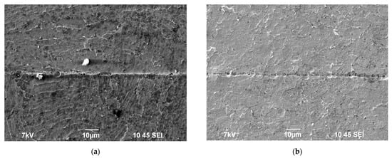
Figure 17.
Surfaces of the coarse-grained (a) and UFG (b) specimens of the titanium alloy (Vh = 100 °C/min, T = 600 °C, t = 10 min, P = 50 MPa) after the electrochemical testing. SEM.
It is worth noting that the corrosion current density icorr in the UFG specimens appeared to be lower than icorr for the welded joints of the coarse-grained specimens, whereas the magnitude of the potential Ecorr was shifted towards more negative values by 10–20 mV. This result evidences indirectly a higher resistance of the specimens with the fine-grained microstructure to the ICC compared to the coarse-grained alloys.
The summarization of the results presented in Table 3 demonstrated the increase in the welding temperature for the UFG alloys from 600 to 800 °C to result in a reduction in the corrosion current density icorr by a factor of ~1.5. The increasing of the heating rate from 50 up to 350 °C/min resulted in the reduction in the icorr from 1.32 down to 0.16 µA/cm2. Increasing the applied stress and the holding time did not result in any considerable change in the electrochemical corrosion characteristics of the welded joints in the UFG alloys (Table 3).
In the case of the coarse-grained specimens, no unambiguous dependence of the corrosion current density on the main parameters of the welding was found. In our opinion, it was caused by the essential nonuniformity of the metal microstructure near the welded joints (as one can see in Figure 13, a situation wherein fragments with different microstructure types appear in two arbitrary areas of the welded joints occurs frequently enough). The small ranges of the linear Tafel parts of the curves ln[i] – E may be the second key factor. This may evidence a significant contribution to the chemical dissolving of the GBs when testing the Ti alloys testing in the environment used.
An unambiguous correlation between the results of electrochemical investigations (the magnitude of icorr) and the results of the HSC testing (the magnitudes hav, hmax) was absent. This is probably because, besides the structural, chemical, and phase composition of the GBs, the electrochemical corrosion intensity may be affected additionally by the porosity of the welded joints: the presence of pores would increase the free surface area and the corrosion rate (Figure 17). It was confirmed indirectly by the fact that the icorr for the specimens with high joint porosity appeared to be greater than the one for the specimens with a small volume fraction of pores in the welded joints. In particular, the icorr for the fine-grained specimens with high porosity of the welded joints (specimens Series #1, 5, 10–12 in Table 3) was ~1.13 mA/cm2. This value appeared to be greater than the mean corrosion current density for the UFG specimens with low and intermediate porosities of the welded joints (icorr~0.91 mA/cm2).
3.6. Microhardness Test
The results of the microhardness test (Table 2) demonstrated that the welding regimes do not affect the Hv of the welded joints and the metal outside the joint line in the coarse-grained alloy. The alloy microhardness far away from the junction line was close to one of the joint materials, and, as a rule, both of these magnitudes were within the range of 2.4–2.6 GPa. Increased values of the Hv of the welded joints compared to the one of alloy before the diffusion welding (~2.1–2.2 GPa) are related, first of all, to the strain hardening, which the specimens undergo in the course of SPS. This conclusion is confirmed indirectly by a notable increase in the joint Hv to 2.7 GPa in the case of the diffusion welding under the stress of 100 MPa (Table 2).
The Hv of the UFG metal inside the welded joints and far away from the joint line exceeded the microhardness of the coarse-grained specimens by ~0.4–0.8 GPa. The highest values of Hv ~3.0–3.2 GPa were observed in the specimens obtained by the SPS at low temperatures, high heating rates, or small holding times. The summary of the obtained results shows that the heating rate increasing to 350 °C/min leads to the formation of the fine-grained microstructure with low porosity and increased hardness (2.9–3.1 GPa) of the welded joints. The increase in the holding time from 0 to 90 min (at Vh =100 °C/min, P = 50 MPa, T = 700 °C) decreased the Hv from 2.9 GPa to 2.5 GPa. The increase in the stress from 50 to 100 MPa at 700 °C resulted in an insufficient increase in the Hv from 2.8–2.9 GPa to 3.0–3.1 GPa but was associated with a strain hardening of the specimens. In our opinion, the most preferable is the diffusion welding performed by high-speed heating (350 °C/min) up to a temperature close to the α→β phase transition temperature (700 °C) at the stress 50 MPa, without holding (t = 0 min). This ensures the formation of the fine-grained microstructure simultaneously with increased hardness and corrosion resistance.
4. Discussion
As noted in the Introduction, the HSC is one of the most dangerous fracture processes for the titanium alloys used in nuclear power engineering and naval aviation. The analysis of the literature data [26,53,54,55,68] shows the air access into the test cell leads to intercrystalline HSC in the α- and near-α titanium alloys. At given testing conditions (the composition of the medium, the temperatures of testing, availability of the access of oxygen, etc.) the tendency of the α- and near-α titanium alloys to the intercrystalline HSC depends, first of all, on the microstructure, chemical, and phase composition of the GBs.
In our case, the most notable effect on the tendency of the near-α alloy Ti-5Al-2V to HSC may cause (i) the concentration of the corrosion-active alloying elements at the GBs, (ii) the nucleation of the β-particles at the GBs as well as (iii) the presence of pores in the welded joints. According to [26,67,68,69], the formation of the grain boundary segregations of the corrosion-active alloying elements, first of all, of vanadium and aluminum [26] as well as the presence of the β-particles containing a high concentration of β-stabilizers (vanadium) [1,2,26,66] can lead to ICC. In other multi-alloyed titanium alloys, the β-phase particles can contain increased concentrations of the alloying elements, providing the thermodynamic stability of the high-temperature β-phase at room temperature. Such elements include Fe, Ta, Nb, Mo, etc. The incorporation of the alloying elements into the crystal lattice of the β-phase changes its electrochemical (electrode) potential. This leads to the appearing of the microgalvanic couples α/β in the microstructure of the titanium alloy. The α/β interphase boundaries promote the acceleration of intercrystalline corrosion. So far, in our opinion, the situation when the β-particles are located at the α-phase grain boundaries is the most dangerous.
The negative effect of the pores is realized, first of all, via the increasing of the free surface area participating in the chemical or electrochemical reactions. If the HSC testing is conducted under stress (see [53,54,58,59,60]), the effect of the pores may be more essential because these may play the role of the initiators of the microcrack formation. It can be related, in particular, to the accumulation of the gaseous corrosion reaction products (hydrogen, TiCl4).
Earlier, it was reported also on the possibility of nucleation of α2-nanoparticles and of α″-phase ones during annealing [70] and of the superplastic deformation [71] of the UFG PT-3V alloy obtained by the Multidirectional Forming method (the deformation temperature was 500–800 °C) followed by annealing at 700 °C (1 h). The nanometer-sized particles nucleated inside the α-Ti grains as well as at the GBs and provided improved stability of the Ti alloy microstructure at heating up and deformation [70,71]. During diffusion welding by SPS, the deformation of the coarse-grained alloy goes via the power-law creep mechanism, and in the case of the UFG alloys—it goes via superplasticity (see [50]). As a consequence, in general, one can expect also the nucleation of the α2-nanoparticles and of the α″-phase ones during the diffusion welding of the Ti alloys by SPS. We think these particles affect the corrosion resistance of the Ti alloy insufficiently since the sizes and volume fractions of these are small, and, according to [72], these would affect the Ti alloy properties by indirectly affecting the α-Ti grain sizes.
Let us analyze the effect of the diffusion welding regimes on the corrosion resistance of the specimens of the coarse-grained and UFG titanium alloy on the HSC. To simplify further analysis, let us assume that the plastic deformation of the metal in the course of diffusion welding affects the ICC intensity, first of all, by affecting the porosity, microstructure state, and phase composition of the GBs in the alloy.
Note, only the joint use of SPS and warm ECAP technologies provides conditions for obtaining UFG welded specimens with increased hardness and corrosion resistance. The resistance of the titanium alloy to intercrystalline corrosion is most affected by ECAP, which is performed at elevated temperatures. Warm SPD allows for reducing the concentrations of alloying elements (vanadium) at the titanium grain boundaries and fragmentation of the large β-phase particles. The key role of SPS is to minimize the grain growth at high-speed heating of the UFG titanium. Since vanadium is a horophilic element in titanium, grain growth can lead to an increase in the local concentration of vanadium at the grain boundaries. Increasing the grain sizes will lead to a decrease in the areas of the grain boundaries and, as a consequence, to an increase in the local concentration of vanadium at the grain boundaries. This can lead to a decrease in the corrosion resistance of the recrystallized titanium alloy. Therefore, only the combined application of ECAP and SPS provides the necessary conditions to obtain high-density welded joints with high corrosion resistance.
4.1. Corrosion Resistance of Welded Joints. Crevice Corrosion
It should be noted in advance that usually α- and near-α Ti alloys intended for nuclear engineering demonstrate a high resistance against crevice corrosion in the chloride solutions [10,72]. Therefore, the observation of intensive crevice corrosion in the welded joints obtained by diffusion welding was unexpected. According to [72], the crevice corrosion in Ti alloys is modeled usually by testing a set of Ti plates with Teflon gaskets in highly concentrated aqueous NaCl solution with the addition of hydrochloric acid at elevated temperatures. We suppose the rapid crevice corrosion to originate from the formation of an active acidic environment with very low pH in very narrow joint macrodefects. This suggestion corresponds to the staging of chemical reactions in the HSC of Ti alloys. The authors of [54,55,56] related HSC in Ti alloys to a sequence of the following reactions:
TiO2 (solid) + 2NaCl (solid) + H2O (gas) → Na2TiO3 (solid) + 2HCl (gas).
The oxide film on Ti reacts with the crystalline salts and water with the formation of sodium titanate Na2TiO3 and hydrochloride HCl, which then reacts with Ti with the release of atomic hydrogen and gaseous titanium chloride IV (TiCl4):
Ti (solid) + 4HCl (gas) → TiCl4 (gas) + 4H (gas).
Hydrogen would be absorbed by the metal at the moment of release and would lead to the hydrogenation of the one at the places of corrosion, whereas titanium chloride IV would undergo hydrolysis in the water vapor with the formation of hydrochloride and, finally, of titanium oxide (TiO2) via a number of intermediate products of hydrolysis:
TiCl4 (gas) + H2O (gas) → TiO2 (solid) + 4 HCl (gas).
Hydrochloride may then react with Ti by reaction (2) with the formation of titanium chloride IV (TiCl4) and so on. This sequence of reactions explains, in our opinion, the high rate of HSC in the testing of the welded specimens with narrow joint macrodefects.
As mentioned above, the crevice corrosion took place within the welded joints preferentially. The corrosion rate of the welded joints correlated well with the presence and sizes of the macrodefects and macropores in the welded joints—the higher the porosity of the joints and the greater the initial size of the joint macrodefect in Zone I, the more intensive the HSC. As one can see from Table 2 and Table 3, crevice corrosion was observed in the corrosion tests of the coarse-grained specimens with high weld porosity. In the coarse-grained specimens, Series #4 and #5 featured low porosity, and the crevice corrosion was almost absent (the depths of the corrosion defects were small and did not exceed 10–20 μm).
In general, a similar situation takes place in the testing of the UFG specimens—the crevice corrosion was observed in the specimens in Series #1, #3, and #12 with high weld porosity. It is interesting to note that in the UFG specimens in Series #10 and #11 obtained at increased stress, no traces of crevice corrosion were found. Probably, the absence of the crevice corrosion traces in these specimens is because the porosity of these is preferential due to the formation of isolated macropores owing to intense plastic deformation, not to the formation of macrodefects of the joints. The presence of the crevice corrosion in the specimens in Series #4 obtained by welding in the β-region is probably due to the flattening of the specimen at its deformation at 1142 °C. This leads to a rise in strong tensile strain along the weld line and, hence, to the fracture of the weld and the formation of new joint macrodefects in this one (Figure 1c). It allows us to conclude that the joint macrodefects, not the isolated macropores, are the most dangerous type of defects in the scope of the crevice corrosion development in the specified conditions of high-temperature testing in the crystal salt mixture. Small sizes of the joint macrodefects and smaller volume fraction of the macropores in the UFG alloys (Figure 6) provide a higher resistance of these against the crevice corrosion compared to the coarse-grained specimens. The nature of accelerated diffusion weldability in the UFG alloy compared to the coarse-grained specimens was described in [50]. In addition, it is worth noting that in order to ensure high resistance of the welded joints against the crevice corrosion, it is more reasonable to perform diffusion welding in the molds limiting the plastic deformation of the Ti alloys at elevated temperatures. This allows for minimizing the negative effect of the tensile strain acting along the weld line and arising at the loss of the shape stability of the specimens but may lead to the carbon contaminations of the surface layers of the Ti specimens [53,73,74].
4.2. Corrosion Resistance of the Metal. Pitting and Intercrystalline Corrosion
Let us analyze now the corrosion resistance of the metal far away from the welding area. As shown in the Results section, far away from the welded joint line, the corrosion destruction preferentially moves via the intercrystalline corrosion mechanism. This suggests that the structure, chemical, and phase composition of the GBs in the Ti alloy affects the corrosion resistance of the metal.
First, let us analyze the effect of the welding temperature on the corrosion resistance of the welded coarse-grained and UFG specimens (specimens in Series #1–4 in Table 2 and Table 3).
Note that after heating with the rate Vh = 100 °C/min up to the temperature 600 °C and holding for 10 min at 50 MPa, the hav reduced from 400–600 µm (Series #0) to 162 ± 43 µm (Series #1), and the corrosion resistance of the coarse-grained alloy came close to the corrosion resistance of the UFG alloys (Table 3). This evidences the improvement of the corrosion resistance of the coarse-grained titanium alloy Ti-5Al-2V by heating. Since no essential changes in the grain sizes and the volume fraction of the β-particles takes place at such a treatment (Table 2), the decrease in the local concentration of vanadium at the titanium GBs is the most probable origin of increased corrosion resistance. This, in our opinion, originates from the diffusion equalization of the local V concentration between the GBs enriched with V and the depleted GBs. It takes place probably because of the action of Fick’s law, resulting in a reduction in the difference in V concentrations between the I-type GBs and the II-type ones in the Ti alloy. The plastic deformation of the Ti alloy may be an additional possible origin of accelerated diffusion mass transfer.
As shown in Table 3, further increasing the welding temperature of the coarse-grained alloy resulted in a slight decrease in the hav.
The structural investigations demonstrated the mean size of the equiaxial grains of α-phase and the structural-phase state of the GBs of these almost did not change in the course of heating the coarse-grained Ti-5Al-2V alloy. However, an inessential increase in the elongated α-phase grain sizes and, most importantly, an increase in the sizes and volume fraction of the β-particles was observed (Table 2). The most clearly this was expressed after welding at 800 °C corresponding to the two-phase (α + β) region. This result agrees well with the data reported in [14,75,76] where the annealing in the intermediate (α + β)-region was demonstrated to result in the increasing of the β-particle sizes with a simultaneous decrease in the vanadium concentration in GBs. It favored a reduction in the ICC intensity in the coarse-grained specimens.
As shown in Table 3, the effect of the heating temperature on the corrosion resistance of the UFG alloys had another character: the increase in the welding temperature increased the depth of the corrosion defects.
As shown above, the microstructure of the UFG alloy Ti-5Al-2V in the initial state was close enough to the microstructure of pure titanium (the grain boundary vanadium segregations and the large β-particles were absent). However, it is worth noting that the recrystallization starts in the UFG alloy Ti-5Al-2V when heating at 500–550 °C (see [26,50]). A fast grain boundary migration increases the local concentration of the vanadium at the GBs. (The distribution coefficient of vanadium in titanium is ~0.801 [77]; hence (see [13]), vanadium is a horophilic alloying element in titanium.) This factor is one of the main origins of the decrease in the corrosion resistance of the UFG alloys with increasing temperatures (Table 2). In the case of increasing the welding temperature up to (α + β)-region, the formation and growth of the β-particles may be an additional factor promoting the decreasing of the corrosion resistance of the UFG alloys.
Now, let us analyze the effect of the holding time on the corrosion resistance of the Ti alloy (specimens in Series #12–15 in Table 3). The welding was performed at 700 °C, near the (α + β)-region boundary.
As one can see from Table 3, the increasing of the diffusion welding time from 0 up to 90 min resulted in the decreasing of the hav and hmax in the coarse-grained specimens. Note that the isothermic holding at this temperature resulted in a partial dissolving of the β-particles (Table 2). Since the β-particles contain an increased V concentration, the presence of these at the GBs causes the formation of the microgalvanic pairs provoking the ICC. In the case of decreasing the volume fraction of the β-particles (that has been observed when increasing the isothermic holding time at 700 °C), one should expect an increase in the corrosion resistance of the coarse-grained alloy.
As shown in Table 3, the increase in the welding time of the UFG specimens resulted in an increase in the depth of the corrosion defects. Note that increasing the holding time at 700 °C would also result in more intensive grain growth (Table 2), hence increasing the concentration of the vanadium at the migrating GBs. This would increase the depth of the ICC defects that have been observed in the experiment (Table 3).
Increasing the heating rate did not affect the corrosion resistance of the coarse-grained specimens (Series #5–8) but led to a nonmonotonous variation in the depth of the corrosion defects in the UFG specimens (Table 3).
Decreasing the corrosion defect sizes in the UFG alloys with increasing heating rates may be explained in the same way: decreasing the heating duration would result in a reduction in the grain growth intensity (Table 2) and a reduction in the harmful element concentration at the GBs. This should decrease the depth of the corrosion defects at high heating rates. At low heating rates (Vh = 10 °C/min), the pitting corrosion only has been observed in the welded UFG specimens (Table 3, Series #5) which did not allow for properly comparing the specimens obtained at high and low heating rates.
The microstructure analysis demonstrated the volume fraction of the nucleated β-particles to be large enough (Table 3). However, it did not result in an essential reduction in the corrosion resistance of the alloy. The mean depth of the ICC defects in the coarse-grained welded specimen was ~184 ± 35 µm, and in the UFG specimen, it was 211 ± 45 µm (Table 3). In our opinion, it is related to the disappearing of the grain boundary segregations of vanadium after heating up to the β-region, whereas the nucleated β-particles contain a lower concentration of the vanadium that coincides well with [14,75,76,78,79].
Note also that the suggestion on the role of V in the HSC of Ti alloys agrees well with the results of the XRD phase analysis. As it was shown above, various V-based phases (VO1.15, V2Ti3O9, Al3V) were found in the corrosion products on the surfaces of the specimens welded at low and moderate temperatures. According to the XRD phase analysis, the Al-based phases (in the presence of vanadium oxides) dominated the HSC products of the specimens welded at elevated temperatures in the β-region instead of the V-based phases. This, in our opinion, is in agreement with the suggestion that the control of the grain boundary segregations of V and the content of the β-phase particles with increased V concentrations in the welded specimens of the Ti-5Al-2V alloy plays an important role in ensuring high resistance to HSC.
5. Conclusions
- The effect of the regimes of high-speed diffusion welding by SPS on the density and microstructure of the near-α titanium alloy Ti-5Al-2V (Russian industrial grade PT-3V) has been investigated. The UFG specimens have been shown to have higher weldability compared to the coarse-grained alloys in the welded joints wherein the macrodefects and macropores provoking the crevice corrosion were observed. In the UFG specimens, the joint macrodefects were practically absent, and the volume fractions of the macro- and micropores were very small which makes the welded joints highly resistant to crevice corrosion.
- The corrosion resistance of the coarse-grained Ti-5Al-2V alloy specimens after the diffusion welding was shown to exceed the corrosion resistance of the alloy in the initial state. Outside of the welded joints, the HSC of the coarse-grained specimens goes by the intercrystalline and pitting corrosion mechanisms. The corrosion defects were distributed over the surfaces of coarse-grained specimens nonuniformly and were concentrated mainly in the area of the fine-grained elongated α-grain, at the grain boundaries of which an increased volume fraction of the β-particles was observed. The HSC of the coarse-grained specimens has a two-stage character—at the first stage, the intercrystalline corrosion is developing, which then transforms into pitting corrosion.
- The corrosion resistance of the UFG alloy Ti-5Al-2V was found to depend mainly on the concentration of the corrosion-active alloying elements (vanadium) at the titanium grain boundaries. Increasing the local concentration of vanadium on the migrating grain boundaries in the titanium alloy with increasing temperatures and diffusion welding times negatively affects resistance against the HSC. The diffusion welding performed by the temperature close to the α→β phase transition boundary (700 °C) at the stress 50 MPa while holding (t = 10 min) was shown to be the most preferable. It ensures the formation of the fine-grained microstructure with simultaneously increased hardness and corrosion resistance.
Author Contributions
Conceptualization, V.C. and A.N.; methodology, V.C. and A.N.; formal analysis, V.C. and A.N.; investigation, C.L., V.K., P.A., M.B., N.T. and A.M.; resources, V.C.; data curation, A.N.; writing—original draft preparation, V.C. and A.N.; writing—review and editing, V.C. and A.N.; visualization, A.N.; supervision, V.C.; project administration, V.C.; funding acquisition, V.C. All authors have read and agreed to the published version of the manuscript.
Funding
This research was funded by the Ministry of Science and Higher Education of the Russian Federation, grant number H-498-99_2021-2023 (075-15-2021-1332) of the Federal academic leadership program Priority 2030. The investigations of the microstructure of the alloys by TEM were carried out using the instrumentation of the Center Collective Use “Materials Science and Metallurgy” (National University of Science and Technology “MISIS”) supported by the Ministry of Science and Higher Education of the Russian Federation (grant No. 075-15-2021-696).
Data Availability Statement
Not applicable.
Acknowledgments
The authors are grateful to D.A. Gudz’ for assistance in the XRD experiments. The authors are also grateful to M.M. Vostokov for assistance in preparing the samples for investigations.
Conflicts of Interest
The authors declare no conflict of interest.
Abbreviations
CG—coarse-grained (alloy); ECAP—Equal Channel Angular Pressing; ICC—intercrystalline corrosion; GB—grain boundary; HSC—hot salt corrosion; RT—room temperature; SEM—scanning electron microscopy; SPD—Severe Plastic Deformation; SPS—Spark Plasma Sintering; TEM—transmission electron microscopy; UFG—ultrafine-grained (alloy); XRD—X-ray diffraction (phase analysis).
References
- Lütjering, G.; Williams, J.C. Titanium, 2nd ed.; Springer: Berlin/Heidelberg, Germany, 2007; p. 442. [Google Scholar]
- Jafee, R.I.; Burte, H.M. (Eds.) Titanium Science and Technology; Springer: New York, NY, USA, 1973; p. 2739. [Google Scholar]
- Gorynin, I.V.; Chechulin, B.B. Titan in Mechanical Engineering; Mashinostroenie: Moscow, Russia, 1990; p. 400. (In Russian) [Google Scholar]
- Bilobrov, I.; Trachevsky, V. Approach to modify the properties of titanium alloys for use in nuclear industry. J. Nucl. Mater. 2011, 415, 222–225. [Google Scholar] [CrossRef]
- Oryshchenko, A.S.; Gorynin, I.V.; Leonov, V.P.; Kudryavtsev, A.S.; Mikhaylov, V.I.; Chudakov, E.V. Marine titanium alloys: Present and future. Inorg. Mater. Appl. Res. 2015, 6, 571–579. [Google Scholar] [CrossRef]
- Leonov, V.P.; Gorynin, I.V.; Kudryavtsev, A.S.; Ivanova, L.A.; Travin, V.V.; Lysenko, L.V. Titanium alloys in steam turbine construction. Inorg. Mater. Appl. Res. 2015, 6, 580–590. [Google Scholar] [CrossRef]
- Gorynin, I.V. Titanium alloys for marine application. Mater. Sci. Eng. A. 1999, 263, 112–116. [Google Scholar] [CrossRef]
- Leonov, V.P.; Chudakov, E.V.; Malinkina, Y.Y. The influence of microadditives of ruthenium on the structure, corrosive-mechanical strength, and fractography of destruction of pseudo-alpha-titanium alloys. Inorg. Mater. Appl. Res. 2017, 8, 556–565. [Google Scholar] [CrossRef]
- Kozhevnikov, O.A.; Nesterova, E.V.; Rybin, V.V.; Yarmolovich, I.I. Influence of neutron irradiation of deformability and fracture micromechanisms of titanium α-alloys. J. Nucl. Mater. 1999, 271–272, 472–477. [Google Scholar] [CrossRef]
- Malinkina, Y.Y.; Chudakov, E.V.; Leonov, V.P. The influence of ruthenium on structure, corrosion and mechanical properties, and fatigue characteristics of titanium α-alloys in corrosive environment. Inorg. Mater. Appl. Res. 2017, 8, 906–913. [Google Scholar] [CrossRef]
- Murashov, A.A.; Berendeyev, N.N.; Nokhrin, A.V.; Galaeva, E.A.; Chuvil’deev, V.N. Investigation of the process of fatigue and corrosion-fatigue destruction of pseudo-α titanium alloy. Inorg. Mater. Appl. Res. 2022, 13, 349–356. [Google Scholar] [CrossRef]
- Segal, V. Review: Modes and Processes of Severe Plastic Deformation. Materials 2018, 11, 1175. [Google Scholar] [CrossRef]
- Segal, V.M.; Beyerlein, I.J.; Tome, C.N.; Chuvil’deev, V.N.; Kopylov, V.I. Fundamentals and Engineering of Severe Plastic Deformation; Nova Science Publishers: New York, NY, USA, 2010; p. 542. [Google Scholar]
- Gornakova, A.S.; Straumal, A.B.; Khodos, I.I.; Gnesin, I.B.; Mazilkin, A.A.; Afonikova, N.S.; Straumal, B.B. Effect of composition, annealing temperature, and high pressure torsion on structure and hardness of Ti-V and Ti-V-Al alloys. J. Appl. Phys. 2019, 125, 082522. [Google Scholar] [CrossRef]
- Straumal, B.B.; Kilmametov, A.R.; Ivanisenko, Y.; Mazilkin, A.A.; Valiev, R.Z.; Afonikova, N.S.; Gornakova, A.S.; Hahn, H. Diffusive and displacive phase transitions in Ti-Fe and Ti-Co alloys under high pressure torsion. J. Alloys Compd. 2018, 735, 2281–2286. [Google Scholar] [CrossRef]
- Alkazraji, H.; El-Danaf, E.; Wolfmann, M.; Wagner, L. Enhanced fatigue strength of commercially pure Ti processed by rotary swaging. Adv. Mater. Sci. Eng. 2015, 2015, 301837. [Google Scholar] [CrossRef]
- Pachla, W.; Kulczyk, M.; Prybysz, S.; Skiba, J.; Wojciechowski, K.; Przybysz, M.; Topolsky, K.; Sobolewski, A.; Charkiewics, M. Effect of severe plastic deformation realized by hydrostatic extrusion and rotary swaging on the properties of CP Ti grade 2. J. Mater. Process. Techn. 2015, 221, 255–268. [Google Scholar] [CrossRef]
- Zherebtsov, S.; Kudryavtsev, E.; Kostjuchenko, S.; Kostjuchenko, S.; Malysheva, S.; Salichchev, G. Strength and ductility-related properties of ultrafine grained two-phase titanium alloy produced by warm multiaxial forging. Mater. Sci. Eng. A. 2012, 536, 190–196. [Google Scholar] [CrossRef]
- Zherebtsov, S.V.; Kudryavtsev, E.A.; Salishchev, G.A.; Straumal, B.B.; Semiatin, S.L. Microstructure evolution and mechanical behavior of ultrafine Ti-6Al-4V during low-temperature superplastic deformation. Acta Mater. 2016, 121, 152–163. [Google Scholar] [CrossRef]
- Czervinski, A.; Lapovok, R.; Tomus, D.; Estrin, Y.; Vinogradov, A. The influence of temporary hydrogenation on ECAP formability and low cycle fatigue life of CP titanium. J. Alloys Compd. 2011, 509, 2709–2715. [Google Scholar] [CrossRef]
- Estrin, Y.; Vinogradov, A. Fatigue behavior of light alloys with ultrafine grain structure produced by severe plastic deformation: An overview. Int. J. Fatigue 2010, 32, 898–907. [Google Scholar] [CrossRef]
- Vinogradov, A.Y.; Stolyarov, V.V.; Hashimoto, S.; Valiev, R.Z. Cyclic behavior of ultrafine-grain titanium processed by severe plastic deformation. Mater. Sci. Eng. A. 2001, 318, S0921–S5093. [Google Scholar] [CrossRef]
- Kral, P.; Dvorak, J.; Zherebtsov, S.; Salishchev, G.; Kvapilova, M.; Sklenichka, V. Effect of severe plastic deformation on creep behaviour of a Ti-6Al-4V alloy. J. Mater. Sci. 2013, 48, 4789–4795. [Google Scholar] [CrossRef]
- Kral, P.; Dvorak, J.; Blum, W.; Kudryavtsev, E.; Zherebtsov, S.; Salishchev, G.; Kvapilova, M.; Sklenichka, V. Creep study of mechanisms involved in low-temperature superplasticity of UFG Ti-6Al-4V processed by SPD. Mater. Charact. 2016, 116, 84–90. [Google Scholar] [CrossRef]
- Balyanov, A.; Kutnyakova, J.; Amirkhanova, N.A.; Stolyarov, V.V.; Valiev, R.Z.; Liao, X.Z.; Zhao, Y.H.; Jiang, Y.B.; Xu, H.F.; Lowe, T.C.; et al. Corrosion resistance of ultrafine-grained Ti. Scr. Mat. 2004, 51, 225–229. [Google Scholar] [CrossRef]
- huvil’Deev, V.N.; Kopylov, V.I.; Nokhrin, A.V.; Tryaev, P.V.; Kozlova, N.A.; Tabachkova, N.Y.; Lopatin, Y.G.; Ershova, A.V.; Mikhaylov, A.S.; Gryaznov, M.Y.; et al. Study of mechanical properties and corrosive resistance of ultrafine-grained α-titanium alloy Ti-5Al-2V. J. Alloys Compd. 2017, 723, 354–367. [Google Scholar] [CrossRef]
- Mosleh, A.O.; Mikhaylovskaya, A.V.; Kotov, A.D.; Sitkina, M.; Mestre-Rinn, P.; Kwame, J.S. Superplastic deformation behavior of ultra-fine-grained Ti-1V-4Al-3Mo alloy: Constitutive modeling and processing map. Mater. Res. Expr. 2019, 6, 096584. [Google Scholar] [CrossRef]
- Raltson, K.; Birbilis, N. Effect of grain size on corrosion: A review. Corrosion 2010, 66, 0750051–07500513. [Google Scholar] [CrossRef]
- Gu, Y.; Ma, A.; Jiang, J.; Li, H.; Song, D.; Wu, H.; Yuan, Y. Simultaneously improving mechanical properties and corrosion resistance of pure Ti by continuous ECAP plus short-duration annealing. Mater. Charact. 2018, 138, 38–47. [Google Scholar] [CrossRef]
- Fattah-alhosseini, A.; Imantalab, O.; Ansari, G. The role of grain refinement and film formation potential on the electrochemical behavior of commercial pure titanium in Hank’s physiological solution. Mater. Sci. Eng. C. 2017, 71, 827–834. [Google Scholar] [CrossRef]
- Chojnaka, A.; Kawalko, J.; Koscielny, H.; Guspiel, J.; Drewienkiewicz, A.; Bieda, M.; Pachla, W.; Kulczyk, M.; Sztwierthia, K.; Beltowska-Lehman, E. Corrosion anisotropy of titanium deformed by the hydrostatic extrusion. Appl. Surf. Sci. 2017, 426, 987–994. [Google Scholar] [CrossRef]
- Kim, H.S.; Kim, W.J. Annealing effects on the corrosion resistance of ultrafine-grained pure titanium. Cor. Sci. 2014, 89, 331–337. [Google Scholar] [CrossRef]
- Kim, H.S.; Yoo, S.J.; Ahn, J.W.; Kim, D.H.; Kim, W.J. Ultrafine grained titanium sheets with high strength and high corrosion resistance. Mater. Sci. Eng. A. 2011, 528, 8479–8485. [Google Scholar] [CrossRef]
- Gurao, N.P.; Manivasagam, G.; Govindaraj, P.; Asokamani, R.; Suwas, S. Effect of texture and grain size on bio-corrosion response of ultrafine-grained titanium. Metall. Mater. Trans. A 2013, 44, 5602–5610. [Google Scholar] [CrossRef]
- Korshunov, A.V.; Il’in, A.P.; Lotkov, A.I.; Ratochka, I.V.; Morozova, T.P.; Lykova, O.N. Reactivity of submicrocrystalline titanium: I. Regulation of oxidation when heated in air. Inorg. Mater. Appl. Res. 2012, 4, 5–12. (In Russian) [Google Scholar]
- Bozhko, P.V.; Korshunov, A.V.; Il’in, A.P.; Lotkov, A.I.; Ratochka, I.V. Reactivity of submicrocrystalline titanium: II. Electrochemical properties and corrosion stability in sulfuric acid solutions. Inorg. Mater. Appl. Res. 2013, 4, 85–91. [Google Scholar] [CrossRef]
- Topol’s’kyi, V.P.; Petrychenko, I.K.; Akhonin, S.V.; Mishchenko, R.M. Weldability of T110 high-strength titanium alloy. Mater. Sci. 2008, 44, 413–417. [Google Scholar] [CrossRef]
- Lukoyanov, A.V. Formation of pores in the weld metal in automatic argon-shielded arc welding of titanium alloys. Welding Int. 2014, 28, 301–303. [Google Scholar] [CrossRef]
- Gao, F.; Li, P.; Jiang, P.; Liao, Z. The effect of constraint conditions on microstructure and properties of titanium alloy electron beam welding. Mater. Sci. Eng. A 2018, 721, 117–124. [Google Scholar] [CrossRef]
- Su, M.-L.; Li, J.-N.; Liu, K.-G.; Qi, W.-J.; Weng, F.; Zhang, Y.-B.; Li, J.-S. Mechanical property and characterization of TA1 titanium alloy sheets welded by vacuum electron beam welding. Vacuum 2019, 159, 315–318. [Google Scholar] [CrossRef]
- Mironov, S.; Sato, Y.S.; Kokawa, H. Friction-stir welding and processing of Ti-6Al-4V titanium alloy: A review. J. Mater. Sci. Techn. 2018, 34, 58–72. [Google Scholar] [CrossRef]
- Meng, X.; Huang, Y.; Cao, J.; Shen, J.; dos Santos, J.F. Recent progress on control strategies for inherent issues in friction stir welding. Progr. Mater. Sci. 2021, 115, 100706. [Google Scholar] [CrossRef]
- Medvedev, A.Y.; Bychkov, V.M.; Selivanov, A.S.; Pavlinich, S.P.; Dautov, S.K.; Supov, A.V. Linear friction welding of two-phase titanium alloys VT6 and VT8-1. Welding Int. 2015, 29, 66–69. [Google Scholar] [CrossRef]
- Nasresfahani, A.R.; Soltanipur, A.R.; Farmanesh, K.; Ghasemi, A. The effect of friction stir welding on corrosion behavior of Ti-6Al-4V. J. Mater. Eng. Perform. 2017, 26, 4311–4318. [Google Scholar] [CrossRef]
- Olevsky, E.; Dudina, D. Field-Assisted Sintering; Springer: Basel, Switzerland, 2018; p. 425. [Google Scholar] [CrossRef]
- Tokita, M. Spark Plasma Sintering (SPS) Method, Systems, and Applications. In Handbook of Advanced Ceramics, 2nd ed.; Somiya, S., Ed.; Academic Press: London, UK, 2013; pp. 1149–1177. [Google Scholar] [CrossRef]
- Hulbert, D.M.; Anders, A.; Dudina, D.V.; Andresson, J.; Jiang, D.; Unuvar, C.; Anselmi-Tamburini, U.; Lavernia, E.J.; Mukherjee, A.K. The absence of plasma in “spark plasma sintering”. J. Appl. Phys. 2008, 104, 033305. [Google Scholar] [CrossRef]
- Ozerov, M.; Klimova, M.; Sokolovsky, V.; Stepanov, N.; Popov, A.; Boldin, M.; Zherebtsov, S. Evolution of microstructure and mechanical properties of Ti/TiB metal-matrix composite during isothermal multiaxial forging. J. Alloys Compd. 2019, 770, 840–848. [Google Scholar] [CrossRef]
- Weston, N.S.; Derguti, F.; Tudball, A.; Jackson, M. Spark plasma sintering of commercial and development titanium alloys powders. J. Mater. Sci. 2015, 50, 4860–4878. [Google Scholar] [CrossRef]
- Chuvil’deev, V.N.; Nokhrin, A.V.; Kopylov, V.I.; Boldin, M.S.; Vostokov, M.M.; Gryaznov, M.Y.; Tabachkova, N.Y.; Tryaev, P. Spark plasma sintering for high-speed diffusion bonding of the ultrafine-grained near-α Ti-5Al-2V alloy with high strength and corrosion resistance for nuclear engineering. J. Mater. Sci. 2019, 54, 14926–14949. [Google Scholar] [CrossRef]
- Yang, J.; Wang, G.; Jiao, X.; Gu, Y.; Liu, Q.; Li, Y. Current-assisted diffusion bonding of extruded Ti-22Al-25Nb alloy by Spark Plasma Sintering: Interfacial microstructure and mechanical properties. J. Mater. Engin. Perform. 2018, 27, 3035–3043. [Google Scholar] [CrossRef]
- Zhao, Z.; Wang, G.; Zhang, Y.; Wang, Y.; Hou, H. Fast recrystallization and phase transformation in ECAP deformed Ti-6Al-4V alloy induced by pulsed electric current. J. Alloys Compd. 2019, 786, 733–741. [Google Scholar] [CrossRef]
- Nokhrin, A.; Andreev, P.; Boldin, M.; Chuvil’deev, V.; Chegurov, M.; Smetanina, K.; Gryaznov, M.; Shotin, S.; Nazarov, A.; Shcherbak, G.; et al. Investigation of microstructure and corrosion resistance of Ti-Al-V titanium alloys obtained by Spark Plasma Sintering. Metals 2021, 11, 945. [Google Scholar] [CrossRef]
- Chevrot, T. Pressure Effects on the Holt-Salt Stress-Corrosion Cracking of Titanium Alloys. Ph.D. Thesis, Cranfield University, School of Industrial and Manufacturing Science, Bedford, UK, 1994. Available online: https://dspace.lib.cranfield.ac.uk/handle/1826/7745 (accessed on 12 April 2023).
- Sinigaglia, D.; Taccani, G.; Vicentini, B. Hot-salt-stress-corrosion cracking of titanium alloys. Cor. Sci. 1998, 18, 781–796. [Google Scholar] [CrossRef]
- Pustode, M.D.; Raja, V.S.; Paulose, N. The stress-corrosion cracking suspeptibility of near-α titanium alloy IMI 834 in presence of hot salt. Cor. Sci. 2014, 82, 191–196. [Google Scholar] [CrossRef]
- Ciszaka, C.; Popa, I.; Brossard, J.-M.; Monceau, D.; Chevalier, S. NaCl induced corrosion of Ti-6Al-4V alloy at high temperature. Cor. Sci. 2016, 110, 91–104. [Google Scholar] [CrossRef]
- Myers, J.R.; Hall, J.A. Hat salt corrosion cracking of titanium alloys: An improved model for the mechanism. Corrosion 1977, 33, 252–257. [Google Scholar] [CrossRef]
- Pustode, M.D.; Raja, V.S. Hot salt stress corrosion cracking behavior of Ti-6242S alloy. Metall. Mater. Trans. A 2015, 46, 6081–6089. [Google Scholar] [CrossRef]
- Pustode, M.D.; Raja, V.S.; Dewangan, B.; Paulose, N. Effect of long term exposure and hydrogen effects on HSSCC behaviour of titanium alloy IMI 834. Mater. Des. 2015, 86, 841–847. [Google Scholar] [CrossRef]
- Joseph, S.; Lindley, T.C.; Dye, D.; Saunders, E.A. The mechanisms of hot salt stress corrosion cracking in titanium alloy Ti-6Al-2Sn-4Zr-6Mo. Cor. Sci. 2018, 134, 169–178. [Google Scholar] [CrossRef]
- Pyshmintsev, I.Y.; Kosmatskii, Y.I.; Filyaeva, E.A.; Illarionov, A.G.; Vodolazskii, F.V.; Barannikova, N.A. Alloy Ti-3Al-2.5V hot-extruded pipe metal structure and properties. Metallurgist 2018, 62, 374–379. [Google Scholar] [CrossRef]
- Illarionov, A.G.; Kostamatskii, Y.I.; Filyaeva, E.A.; Vodolazskii, F.V.; Barannikova, N.A. Experimental determination of temperature parameters for evaluating the possibility of manufacturing alloy Ti-3Al-2.5V hot-extruded tubes. Metallurgist 2017, 60, 983–988. [Google Scholar] [CrossRef]
- Illarionov, A.G.; Vodolazskiy, F.V.; Barannikova, N.A.; Kosmatskiy, Y.I.; Khudorozhkova, Y.V. Influence of phase composition on thermal expansion of Ti-0.4Al, Ti-2.2Al-2.5Zr and Ti-3Al-2.5V alloys. J. Alloys Compd. 2021, 857, 158049. [Google Scholar] [CrossRef]
- Chuvil’deev, V.N.; Kopylov, V.I.; Nokhrin, A.V.; Tryaev, P.V.; Tabachkova, N.Y.; Chegurov, M.K.; Kozlova, N.A.; Mikhaylov, A.S.; Ershova, A.V.; Gryaznov, M.Y.; et al. Effect of severe plastic deformation realized by rotary swaging on the mechanical properties and corrosion resistance of near-α-titanium alloy Ti-2.5Al-2.6Zr. J. Alloys Compd. 2019, 785, 1233–1244. [Google Scholar] [CrossRef]
- Bykh, O.; Bakhmetev, A.; Sandler, N.; Tryaev, P.V.; Ershova, A.V.; Mikhaylov, A.S.; Sozinov, A.N. Hot-salt corrosion of alloys PT-7M, 42XHM, Inconel 690 and Incoloy 800. Appl. Solid State Chem. 2019, 1, 23–31. [Google Scholar] [CrossRef]
- Andreev, P.V.; Gudz, D.A.; Smetanina, K.E. Surface treatment of titanium alloys for the X-ray diffraction study. AIP Conf. Proc. 2020, 2315, 03001. [Google Scholar] [CrossRef]
- Tomashov, N.D.; Chernova, G.P. Theory of Corrosion and Corrosion-Resistant Structural Alloys; Metallurgiya: Moscow, Russia, 1986; p. 358. (In Russian) [Google Scholar]
- Tavadze, F.N.; Mandzhgaladze, S.N. Corrosion Resistance of Titanium Alloys; Metallurgiya: Moscow, Russia, 1969; p. 208. (In Russian) [Google Scholar]
- Tomashov, N.D. Titanium and Titanium-Based Corrosion-Resistance Alloys; Metallurgiya: Moscow, Russia, 1985; p. 80. (In Russian) [Google Scholar]
- Ratochka, I.V.; Lykova, O.N.; Naydenkin, E.V. Influence of low-temperature annealing time on the evolution of the structure and mechanical properties of a titanium Ti-Al-V alloy in the submicrocrystalline state. Phys. Metals Metallogr. 2015, 116, 302–308. [Google Scholar] [CrossRef]
- Ratochka, I.; Lykova, O.; Mishin, I.; Naydenkin, E. Superplastic deformation behavior of Ti-4Al-2V alloy governed by its structure and precipitation phase evolution. Mater. Sci. Eng. A 2018, 731, 577–582. [Google Scholar] [CrossRef]
- Sherbinin, V.F.; Leonov, V.P.; Malinkina, Y.Y. Increase in corrosion resistance of titanium alloy in concentrated aqueous solutions of chlorides at high temperatures. Inorg. Mater. Appl. Res. 2013, 4, 537–541. [Google Scholar] [CrossRef]
- Bokhonov, B.; Ukhina, A.; Dudina, D.; Anisimov, A.G.; Mali, V.I.; Batraev, I.S. Carbon uptake during Spark Plasma Sintering: Investigation through the analysis of the carbide “footprint” in a Ni-W alloy. RSC Adv. 2015, 5, 80228–80237. [Google Scholar] [CrossRef]
- Dudina, D.V.; Bokhonov, B.B.; Ukhina, A.V.; Anisimov, A.G.; Mali, V.I.; Esikov, M.A.; Batraev, I.S.; Kuznechik, O.O.; Pilinevich, L.P. Reactivity of materials towards carbon of graphite foil during Spark Plasma Sintering: A case study using Ni-W powders. Mater. Lett. 2016, 168, 62–67. [Google Scholar] [CrossRef]
- Gornakova, A.S.; Straumal, B.B.; Prokofiev, S.I. Coarsening of (αTi) + (βTi) microstructure in the Ti-Al-V alloy at constant temperature. Adv. Eng. Mater. 2018, 20, 1800510. [Google Scholar] [CrossRef]
- Gornakova, A.S.; Prokofjev, S.I. Energetics of intergranular and Interphase boundaries in Ti-6Al-4V alloys. J. Mater. Sci. 2020, 55, 9225–9236. [Google Scholar] [CrossRef]
- Kristallisationaus Schmelzen; Hein, K., Buhrig, E., Eds.; VEB Deutscher Verlag für Grundstoffindustrie: E. Leipzig, Germany, 1983; p. 356. (In Germany) [Google Scholar]
- Huang, S.; Zhang, J.; Ma, Y.; Zhang, S.; Youssef, S.S.; Qi, M.; Wang, H.; Qiu, J.; Xu, D.; Lei, J.; et al. Influence of thermal treatment on element partitioning in α+β titanium alloy. J. Alloys Compd. 2019, 791, 575–585. [Google Scholar] [CrossRef]
Disclaimer/Publisher’s Note: The statements, opinions and data contained in all publications are solely those of the individual author(s) and contributor(s) and not of MDPI and/or the editor(s). MDPI and/or the editor(s) disclaim responsibility for any injury to people or property resulting from any ideas, methods, instructions or products referred to in the content. |
© 2023 by the authors. Licensee MDPI, Basel, Switzerland. This article is an open access article distributed under the terms and conditions of the Creative Commons Attribution (CC BY) license (https://creativecommons.org/licenses/by/4.0/).

