Article

Characteristics of Bubble Behavior and Inclusion Removal in Liquid Steel Based on Industrial Trials of Argon Injection into Ladle Shroud

1
National Engineering Research Center for Advanced Rolling and Intelligent Manufacturing, University of Science and Technology Beijing, Beijing 100083, China
2
Huawei National Engineering Research Center of High Efficient Cyclic Use of Metallic Mineral Resources Co., Ltd., Ma’anshan 243071, China
*
Author to whom correspondence should be addressed.
Metals 2023, 13(3), 593; https://doi.org/10.3390/met13030593
Submission received: 7 February 2023 / Revised: 28 February 2023 / Accepted: 10 March 2023 / Published: 15 March 2023
(This article belongs to the Special Issue Thermodynamic Properties of Metallurgical Melts)

Abstract

:
A series of industrial trials of argon injection into ladle shroud (AIILS) with different argon-blowing rates were conducted in this study. Firstly, bubbles in actual liquid steel of the tundish were captured by the method of “cold steel plate dipping” and characterized by microscope examination. A detailed investigation on the three-dimension morphology of bubbles was carried out by using industrial computerized tomography (ICT). Then, the two-phase flow of liquid steel and argon gas in the tundish was numerically simulated to further investigate the motion behaviors of bubbles in liquid steel of the tundish. The simulated results showed that bubbles in the size range of this investigation had a large enough filtration rate to demonstrate a good performance on inclusion removal. Finally, the effect of AIILS on inclusion removal was analyzed by detecting the variations of inclusions as well as total oxygen content in steels taken from the ladle, tundish, and casting billet. The method of AIILS was more effective at improving the removal of inclusions in the range of 5 to 10 μm and obviously increased the removal rate of total oxygen content.

1. Introduction

Bubble floatation is an effective approach for removing inclusions in liquid steel. Methods such as argon blowing at the bottom of a ladle and gas curtain in a tundish are typical applications in this domain [1,2,3]. With regard to these methods, the size of bubbles directly generated by gas blowing is relatively coarse, usually with a diameter larger than 10 mm, resulting in a limited effect on inclusion removal. Numerous studies have shown that finely dispersed bubbles have a higher probability of colliding with inclusions in liquid steel, and thus efficiently promote the floatation and removal of inclusions [4,5,6,7,8]. To this end, the formation of finely dispersed bubbles has been one of the vital issues in the field of bubble metallurgy. In the continuous casting process, it has been found that the method of argon injection into ladle shroud (AIILS), which was originally used for protective casting, might be expected to be a new technology for the highly efficient removal of inclusions in liquid steel based on the formation of finely dispersed bubbles [9,10]. When liquid steel is poured from the bottom of a ladle to a tundish via a ladle shroud, its potential energy will be converted into kinetic energy, with a flow velocity of 0.6 to 4.0 m/s. The turbulent shear stress of liquid steel can break up the injected gas into finely dispersed bubbles.
Some investigators have studied the factors affecting the size of fine bubbles formed by AIILS [11,12,13,14,15]. Wang et al. [11] found that the turbulent kinetic energy of liquid steel dominantly affected the size of bubbles. However, the studies by Zhang et al. [12] and Li et al. [13] showed that the size of bubbles was influenced by blowing rate and nozzle size to a much greater extent. For this disagreement, Fan et al. [14] further put forward that there were two stages for the formation of fine bubbles in a ladle shroud. Stage 1 was the desorption of bubbles from the gas nozzle, and Stage 2 was the breakage of bubbles in the turbulent steel stream. They held the opinion that the size of bubbles might be more related to the desorption of bubbles in Stage 1 because in the short duration of Stage 2 it was difficult to meet the requirement of bubble breakage in the turbulent zone. This point was later supported by Chang et al. [15]. They calculated the distribution of turbulence dissipation rate in the ladle shroud and found that the distribution was uneven. The result showed that the turbulent kinetic energy below the sliding plate was the highest, and then it decreased layer by layer.
According to the “two-stage” mechanism by Fan et al. [14], the basic approaches to form fine bubbles based on the method of AIILS are to increase the turbulence dissipation rate of liquid steel and to control the size of bubbles desorbed from the gas nozzle. The opening aperture of sliding nozzle, blowing location, and flow velocity are the main operation parameters affecting the turbulent kinetic energy of liquid steel. Bao et al. [16] found that the fast downward flowing liquid steel had a strong shear stress on the gas from the nozzle to improve the desorption of bubbles and reduce the size of bubbles. The studies by Wang et al. [11] and Li et al. [13] showed that a lower blowing rate corresponded to an earlier desorption of bubbles from the gas nozzle and a better breakage of desorbed bubbles by turbulent steel flow. Zhang et al. [12] found that the size of bubbles decreased with the decreasing inner diameter of gas nozzle. Overall, the size of bubbles initially formed can be reduced by diminishing the inner diameter of gas nozzle and the flow rate of argon blowing. In addition, an increase in the flow velocity of liquid steel can further decrease the size of bubbles formed in the tundish by promoting the desorption of bubbles and increasing the shear stress on bubbles.
In addition to bubble size, the distribution of bubbles in the tundish is also a key issue for inclusion removal. If fine bubbles dispersedly distribute in liquid steel, they will clean and filter a relatively large volume of liquid steel to increase the removal rate of inclusions. It has been found that the flow pattern of gas–liquid flow in the ladle shroud, mainly affected by the condition of argon injection, might influence the distribution of bubbles in the tundish. The study by Singh et al. [17] showed that the flow pattern of gas–liquid flow was related to the volume ratio of gas to liquid. The bubble flow could be formed in the ladle shroud at a volume ratio below 2%. When the volume ratio increased to a range of 2 to 42%, the two flows of gas and liquid were only well-mixed at the lower part of the ladle shroud. Thus, the volume ratio of gas to liquid is usually set in the range of 0 to 10% to ensure a good mixing of bubbles and liquid in the ladle shroud. However, some research also found that the slag “eye” could be formed during the floatation of bubbles to the top slag, which might cause the secondary oxidation of liquid steel [18,19,20]. Based on the water model experiments, Chatterjee et al. [18] thought that the area of slag “eye” was related to flowing rate, bath depth, slag thickness, and bath properties. As a result, the argon-blowing rate should be controlled within a reasonable range to avoid the formation of slag “eye” as much as possible.
In general, the method of AIILS has the ability to generate finely dispersed bubbles in a tundish and therefore enhances the refining effect of tundish metallurgy. However, the existing relevant studies are insufficient to support the industrialization of this method. Most of the studies were conducted using water model experiments and numerical simulations, while few industrial trials have been carried out. Moreover, it is difficult to characterize the size and distribution of bubbles in actual liquid steel. To this end, we recently put forward a method called “cold steel plate dipping” to achieve the bubble characterization [21]. On this basis, in this study, we conducted a series of industrial trials of AIILS with different argon-blowing rates. First, bubbles in actual liquid steel of the tundish were captured relying on the method of “cold steel plate dipping” and then characterized by microscope examination. Second, the motion and distribution of bubbles in the tundish was investigated by numerical simulation to explore the inclusion removal by bubbles. Furthermore, the effect of AIILS on inclusion removal was analyzed by detecting the variations of inclusions as well as O and N contents in steels taken from the ladle, tundish, and casting billet. The obtained results are expected to be informative for the industrialization of AIILS in the field of tundish metallurgy.

2. Materials and Methods

2.1. Industrial Trials of Argon Injection into Ladle Shroud (AIILS)

The industrial trials of AIILS were conducted relying on the 165 mm × 165 mm billet continuous casting process of ER70S-6 welding-wire steel at Aosen Steel located in North China’s Hebei province. The controlled compositions for the steel were 0.080–0.084 C, 0.84–0.87 Si, 1.46–1.55 Mn, 0.011–0.014 P, 0.009–0.020 S, 0.033–0.067 Cr, and 0.014–0.018 Ni (in mass%). The caster was equipped with two four-strand tundishes, each of which had a capacity of 40 t liquid steel. The temperature of liquid steel in the tundishes was controlled between 1532 and 1537 °C, and the casting speed was maintained at 2.6 m·min−1. In addition, MgO-C-based, Al2O3-ZrO2-based, and MgO-based materials were used for the refractory linings of the ladle, shroud, and tundish, respectively. The main chemical compositions for mold power were 31.64 SiO2, 23.75 CaO, 14.34 C, and 7.96 Al2O3 (in mass%). The main chemical composition for tundish power was 56.28 CaO and 19.04 SiO2 (in mass%). In order to avoid secondary oxidation during the continuous casting process, the operation of AIILS was adopted to play a role in protective casting.
Figure 1 shows the schematic diagram of protective casting using AIILS. The tundish is connected with the ladle through a shroud nozzle, and an argon-blowing device is equipped at the link between the shroud nozzle and the slide gate at the bottom of the ladle. The argon gas is firstly blown into the gap between the refractory of shroud nozzle and its external enclosing iron shell. Then, most of the argon gas flows upwards along the gap to the joint of the iron shell, the gasket, and the refractory of shroud nozzle (labeled as Flow A), while the rest goes downwards and eventually escapes to the atmosphere (labeled as Flow B). At the joint, Flow A can be divided into the upward Flow C and the downward Flow D. Flow C forms the argon atmosphere near the junction of the shroud nozzle and the slide gate to hinder the ambient air from being aspirated into the ladle shroud. Meanwhile, Flow D may be sucked into the ladle shroud due to the negative pressure effect and is further broken into fine argon bubbles by the downwards turbulent liquid steel to improve the function of tundish metallurgy. Normally, the argon-blowing rate is set as 1.0 Nm3·h−1 at Aosen Steel, which is designed primarily for Flow C to avoid the aspiration of the ambient air into the ladle shroud. In this study, the argon-blowing rate was remarkably increased in the industrial trials of AIILS in order to further examine the function of Flow D. The industrial trials were carried out on five heats of continuous casting in succession with argon-blowing rates of 0, 1.5, 3.0, 5.0, and 6.5 Nm3·h−1 and labeled as Trials 1, 2, 3, 4, and 5, respectively. Trial 1 without argon blowing acted as a reference.
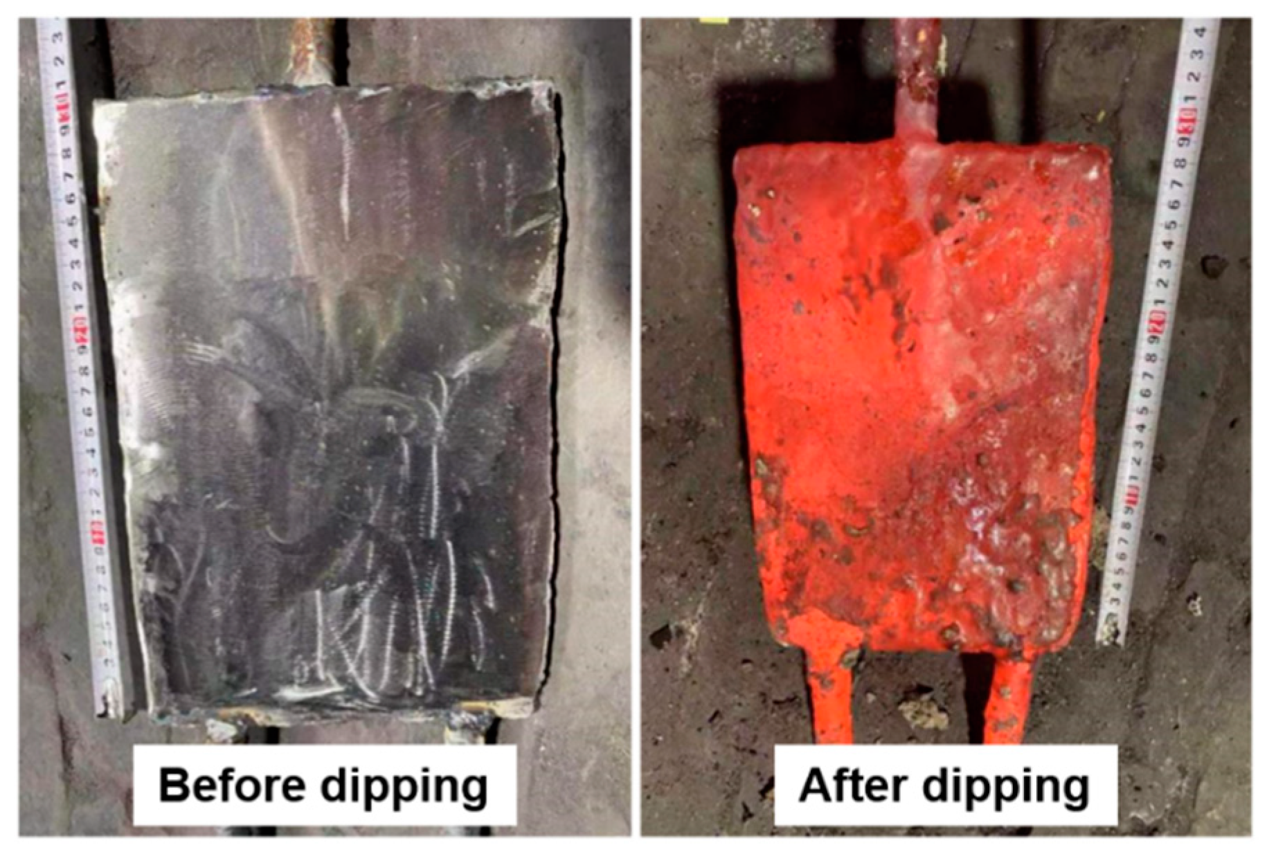
A method called “cold steel plate dipping” was designed to characterize the bubbles in the actual liquid steel of the tundish. As shown in Figure 2, the sampler used for the method consists of a rectangular steel plate, two localization rods, and a handle. The steel plate has a width of 200 mm, a height of 300 mm, and a thickness of 5 mm. This dimension design was used to better characterize the bubble distribution in a vertical direction. The localization rods with a length of 10 cm are used for fixing the distance between the tundish bottom and the steel plate, and the handle for dropping and rising the steel plate. Before dipping into the liquid steel, the surface of the steel plate was polished to remove oxide scale and baked for 10 min to eliminate moisture. For each heat of the continuous casting, the cold steel plate was dipped into the liquid steel in the tundish for 5 to 10 s and then lifted up when the casting had operated for 15 min. The cooling effect of the cold steel plate could precipitate the fast solidification of the surrounding liquid steel to form a layer of steel shell on the surface. Meanwhile, the intrinsic bubbles and inclusions in the surrounding liquid steel were frozen inside the steel shell for further investigation.
Figure 3 shows the sampler before and after dipping into liquid steel. The steel shell was peeled off from the steel plate and machined to slice samples at a size of 20 mm × 20 mm. After the slice samples were polished, the size distributions of bubbles in the samples were investigated using an OLYMPUS LEXT OLS4100 Laser Scanning Microscope (LSM) (Olympus, Tokyo, Japan), and the size of bubbles was further verified using Industrial Computerized Tomography (ICT). The adhesion behavior between bubbles and inclusions was analyzed using a ZEISS ULTRA 55 Scanning Electronic Microscope (SEM) (Carl Zeiss, Oberkochen, Germany) equipped with an Energy Dispersive Spectrometer (EDS).
In addition, the effect of AIILS on inclusion removal was investigated by detecting the variations of inclusions, as well as O and N contents, in steel samples taken from the ladle, tundish, and casting billet. For each Trial, two ladle samples, two tundish samples, and four billet samples were collected. Ladle samples were collected after LF treating and before going to casting machine. Tundish samples were collected when the weight of liquid steel in the ladle decreased from 120 t to 80 t, in order to avoid the impact from the start of pouring. Barrel-shape samplers covered by a wooden lid were used for taking steel samples from the liquid steel in the ladle and the tundish. Machined from the barrel-shape steel ingot, a cubic sample with a size of 10 mm× 10 mm× 10 mm was used for inclusion analysis, and a pair of bar samples with diameters of 5 mm were used for O and N analysis. According to the real-time tracking of continuous casting process, the casting billet related to the investigated liquid steel in the tundish was found. The steel plates with a thickness of 50 mm were cut from the casting billet and acted as billet samples. Machined from the steel plate, five cubic samples at a size of 10 mm× 10 mm× 10 mm were used for inclusion analysis, and two pairs of bar samples with diameters of 5 mm were used for O and N analysis. Inclusion analysis was conducted by the SEM with an INCA Feature software (INCA-Feature, Oxford Instruments, Oxford, UK), and O and N analysis by a LECO TCH600 gas analyzer (LECO, St. Joseph, MI, USA).

2.2. Numerical Simulation of Bubble Motion and Distribution in Tundish

Based on the industrial trials of AIILS, the motion and distribution of bubbles in the tundish was investigated by numerical simulation to further explore the effect of bubbles on inclusion removal. The numerical simulation was conducted using a series of software tools, including AutoCAD 2017 for geometric modeling, ICEMCFD 2019 R3 for mesh dividing, Fluent 2019 R3 for analysis and calculation, and Tecplot 360 for post-processing. Some assumptions have been adopted for simplifying the simulation calculation: (1) the liquid steel was treated as homogeneous incompressible Newtonian fluid; (2) the flow of liquid steel was turbulent in the tundish; (3) the continuous phase had a free surface; (4) the energy transfer in the tundish was ignored; and (5) the bubbles were assumed to be spherical, without volume changes during the floatation.
Considering that the flow of liquid steel was turbulent in the tundish, the injected argon gas should participate in the momentum and mass transfers of liquid steel in the form of bubbles. This was described by the following continuity equation and momentum conservation equation:
x i ( ρ u i ) = 0
t ( ρ u i ) + x j ( ρ u i u j ) = p x i + x j [ μ e f f ( μ i x j + μ j x i ) ] + ρ g i + f
where ρ is the density of continuous phase, kg·m−3; u is the velocity of continuous phase, m·s−1; μ is the viscosity of continuous phase, Pa·s; i and j are the vector directions; p is the pressure, Pa; μeff is the effective viscosity of continuous phase, Pa·s; and g is the gravitational acceleration, m·s−2. The source item f is the momentum transfer between continuous phase and discrete phase, which reflects the effect of bubble motion on the surrounding flow field.
f = d u b d t m b Δ t
where ub is the velocity of bubbles, m·s−1; mb is the mass flow, kg·s−1; Δt is the time step, s.
The standard k-ε turbulence model was adopted to calculate the flow field in the tundish [22,23]. The turbulent kinetic energy k and the turbulent dissipation rate ε were obtained via the following two simultaneous equations:
t ( ρ k ) + x i ( ρ u i k ) = x j ( μ e f f σ k k x j ) + G k ρ ε
t ( ρ ε ) + x i ( ρ u i ε ) = x j [ ( μ e f f + u t σ ε ) ε x j ] + C 1 ε k G k C 2 ε 2 k ρ
The generation rate of turbulent kinetic energy resulting from the average velocity G k and the effective viscosity of continuous phase μ e f f were calculated by the following two equations:
G k = μ t u j x i ( u i x j + u j x i )
μ e f f = μ + μ t = μ + C μ ρ k 2 ε
where μ t is the turbulent viscosity of continuous phase, Pa·s. The constants C 1 , C 2 , C μ , σ ε , and σ k were set according to the recommended values [22], as shown in Table 1.
The discrete phase model (DPM) was adopted to track the bubble motion in the tundish, and the effect of bubble motion on the flow field was considered by coupling the momentum transfer between the continuous phase and discrete phase. The force balance equation of discrete phase was expressed as follows:
d u b d t = F d ( u u b ) + g ( ρ g ρ ) ρ g + F x
where the first item on the right of the equation represents the acceleration resulting from the drag force; the second item represents the acceleration resulting from the resultant of floatation and gravity forces. Considering the obvious difference between gas and liquid phases, F x represents the virtual mass force F m and the pressure gradient force F p exerting on bubbles.
F m = 1 2 ρ ρ g d d t ( u u b )
F d = ( ρ ρ g ) u b u
The random walk model (RWM) was adopted to simulate the diffusion of discrete phase caused by the turbulence of continuous phase, and the instantaneous velocity of continuous phase was expressed as follows:
u = u a v + u
u = ζ 2 k 3
where u a v is the average velocity of continuous phase, m·s−1; u is the instantaneous velocity fluctuation resulting from turbulent flow, m·s−1; and ζ is the standard random distribution factor. The introduction of ζ ensures the randomness of instantaneous velocity fluctuation, and its value and valuable time point are related to the vortex life and the time consumption of vortex crossing discrete phase.
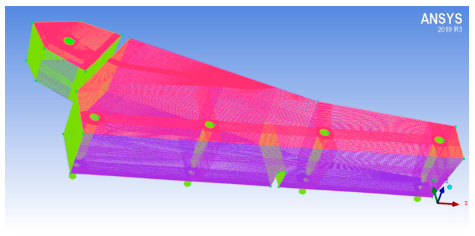
The prototype model for the numerical simulation used the two four-strand tundishes employed at Aosen Steel, where only one-half of the model was considered due to the symmetry of tundish geometry. After the grid independence test, the computational domain, as shown in Figure 4, was discretized with around 2.26 million hexahedral grids, using ANSYS ICEM CFD software (2019R3, ANSYS, Pittsburgh, KS, USA). The local mesh refinement was adopted for the solution of complex flows in the pouring region and ladle shroud.
The inlet boundary of liquid steel was treated as “velocity-inlet”, which depended on casting speed and billet section. According to the actual production data, the size of billet section was 165 mm × 165 mm, the casting speed was 2.6 m·min−1, the temperature of liquid steel at the inlet was 1535 °C, and the inner diameter of the ladle shroud was 85 mm. In addition, the density of liquid steel ρ L was calculated by the empirical formula:
ρ L = 8523 0.8258 T
where is T is the temperature of liquid steel, K. As the energy transfer in the tundish was ignored, the density of liquid steel was treated as a constant value. The flow rate at the ladle shroud v s h r o u d was expressed as follows:
v s h r o u d = 4 · A s e c t i o n · v c a s t i n g A s h r o u d
where A s e c t i o n is the area of billet section, m2; v c a s t i n g is the speed of continuous casting, m·s−1; and A s h r o u d is the area of the ladle shroud, m2. The volume flow rate Q, the turbulent kinetic energy k i , and the turbulent dissipation rate ε i of liquid steel at the inlet were respectively expressed as follows:
Q = 0.8316 × A s h r o u d
k i = 1.5 ( I · v s h r o u d ) 2
ε i = 2 k i 1.5 D
where I is the turbulent intensity and D is the inner diameter of the ladle shroud, m. During the casting process, the whole environment is in circulation with the outside world, and the process is mainly driven by gravity. Thus, the outlet boundary of the tundish was treated as a “pressure-outlet”, and the reference pressure was one standard atmospheric pressure. The upper free liquid surface in the tundish, which takes no account of level fluctuation and ignores surface shear stress, was regarded as a free slip wall boundary and set as the “escape-surface” for DPM particles, meaning that particles were judged to escape from the computational domain once contacting the liquid surface. The solid wall of the tundish was calculated by standard wall function and set as the “reflect-surface” for DPM particles, meaning that particles rebounded when hitting the wall. In addition, DPM considers that the gas phase enters the tundish from the ladle shroud completely in the form of bubbles. According to the industrial trial, the argon-blowing rate at 298 K V t o t a l ,   298 K was set as 3.0 Nm3·h−1, of which 5% was sucked into the ladle shroud due to the negative pressure effect. Considering the volumetric expansion of argon at high temperature, the actual flow rate of argon entering liquid steel at 1808 K, V a c t u a l , 1808 K was calculated by
V a c t u a l , 1808 K = V t o t a l , 298 K × 5 % × ρ A r , 298 K ρ A r , 1808 K
where ρ A r , 298 K is the density of argon at 298 K, kg·m−3; and ρ A r , 1808 K is the density of argon at 1808 K, kg·m−3. In this simulation, bubbles were set to be injected into the flow field in the form of “surface”. The injection plane is the cross-section of the ladle shroud where bubbles evenly distribute.

3. Results and Discussion

3.1. Morphological Characteristics of Bubbles

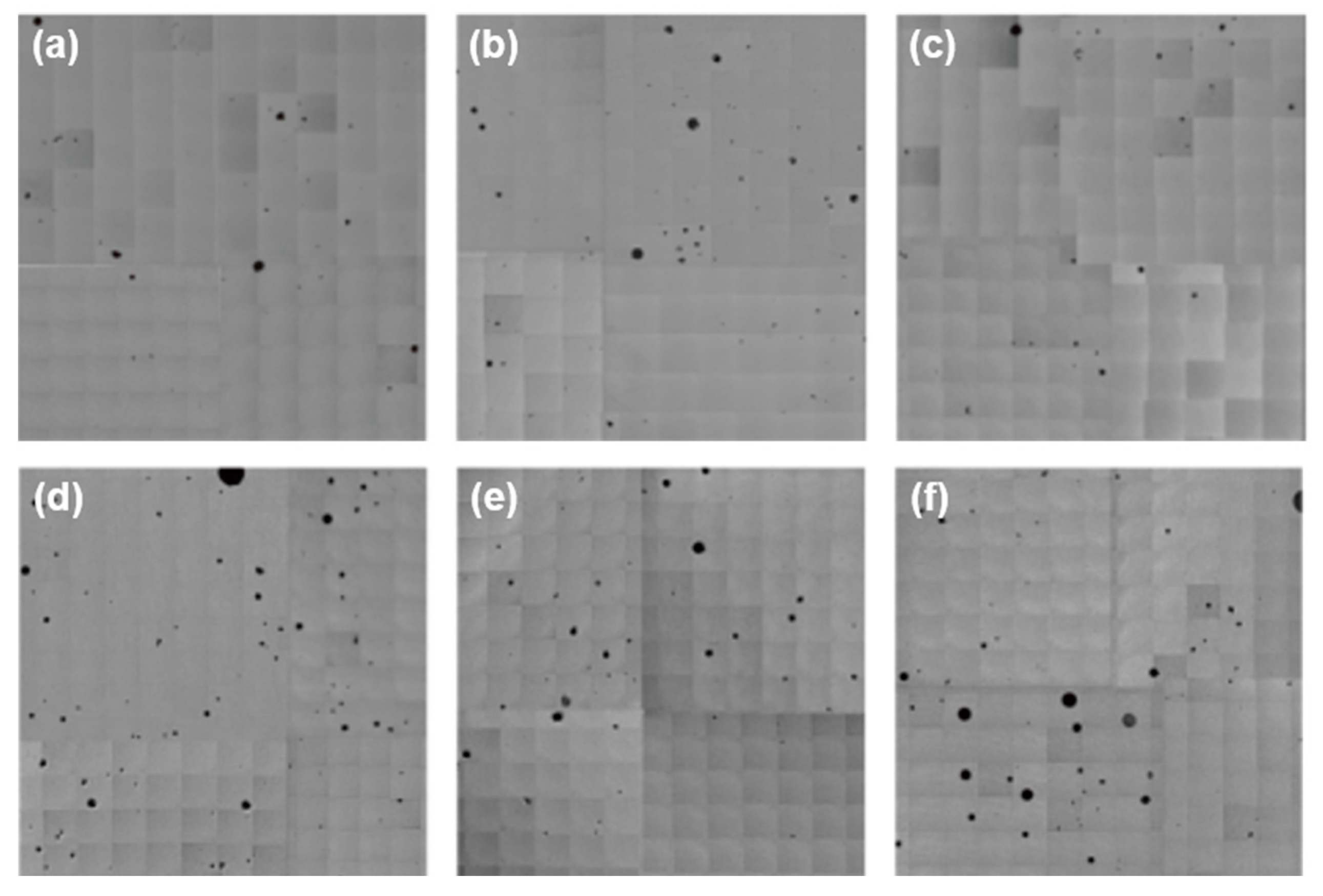
In order to have a general understanding of the distribution of bubbles in the tundish, samples were taken from the upper, middle, and lower portions of the steel shell in the vertical direction to represent liquid steel at different depths in the tundish. According to our findings, there was no special difference in the size and distribution of bubbles for the four trials with argon injection into ladle shroud (AIILS) of this study, although the number of bubbles might rise with an increasing argon-blowing rate. Thus, we selected Trials 3 and 4 as examples to introduce the characteristics of bubbles formed by AIILS.
Figure 5 shows the LSM images of bubble distribution at different depths of the tundish for Trials 3 and 4, with argon-blowing rates of 3.0 and 5.0 Nm3·h−1. Bubbles were dispersedly distributed in the steel samples. The total number of bubbles for Trial 4 was obviously larger than that for Trial 3, which was closely related to the higher argon-blowing rate in Trial 4. Generally, the number of bubbles at the upper portion of impact zone of the tundish was relatively greater compared with the middle and lower portions, with the densities of 9.0 and 13.7 cm−2 for Trials 3 and 4, respectively. Even so, the densities of bubbles at the lower portion for the two trials still reached 6.2 and 9.1 cm−2, indicating that the fine bubbles formed in the ladle shroud can move to the bottom of impact zone of the tundish along with liquid steel flow. Considering the movement of bubbles in liquid steel, the higher flow velocity of bubbles at the middle portion made them difficult to freeze inside the steel shell, and thus the number of bubbles here was smaller than at the upper and lower portions.
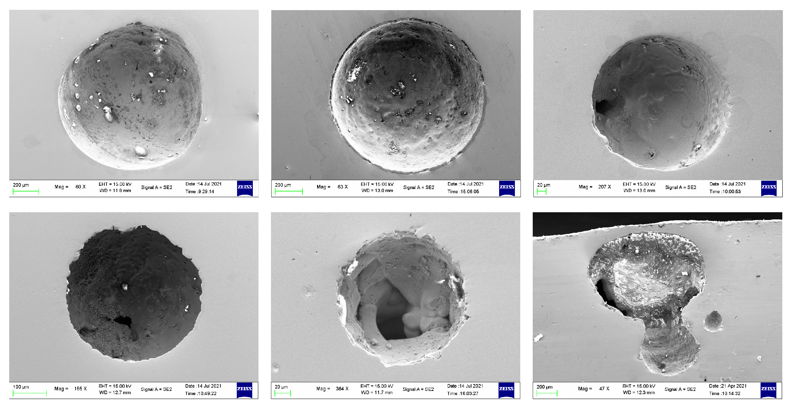
A closer look at the morphology of bubbles was carried out by SEM. Figure 6 shows the SEM images of bubbles captured in liquid steel of the tundish. These bubbles were basically spherical, with a diameter in the range of 100 to 1000 μm. Most of them were single bubble, and some polymerized bubbles could still be found. This indicated that a small portion of fine bubbles might collide and adhere with each other. Considering the spherical morphology of bubbles, the circle diameters shown in the SEM images cannot really represent the actual size of bubbles. To this end, a detailed investigation on the three-dimensional morphology of bubbles inside the steel sample was carried out using ICT in this study.
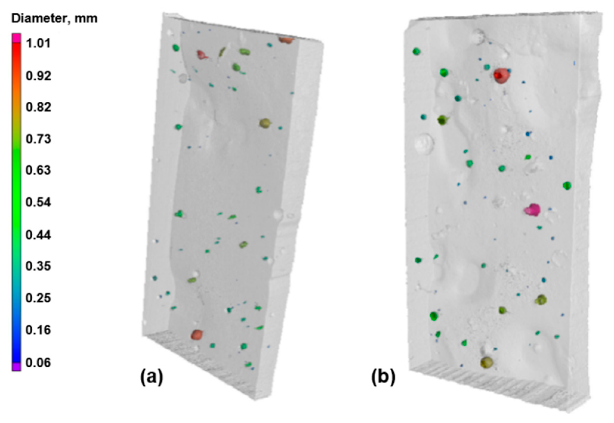
As shown in Figure 7, the ICT inspection results of two steel samples from Trial 3 were taken as an example. It could be found that the diameters of most bubbles were in the range of 350 to 750 μm, and a small portion of bubbles had a diameter around 1000 μm. The average diameters of bubbles for the two steel samples were 524.8 and 525.5 μm, respectively. Therefore, under the industrial production condition in this study, the average diameter of bubbles generated by AIILS was around 500 μm. This result was far less than the result predicted by Yang et al. [9] who thought that the diameters of the bubbles were in the range of 1.5 to 3.5 mm, but it was close to the result calculated by Bai et al. [24], based on the theory of bubble breakage by turbulent kinetic energy. This indicated that the formation mechanism of finely dispersed bubbles by AIILS could be reasonably explained by the theory of bubble breakage by turbulent kinetic energy. However, this theory can only calculate the maximum size of bubbles generated by turbulent kinetic energy. Meanwhile, bubbles are difficult to fully break up in the length-limited ladle shroud. Thus, the theory of bubble breakage by turbulent kinetic energy is not completely applicable to calculating the size of fine bubbles generated by AIILS.

3.2. Motion Behaviors of Bubbles in Tundish

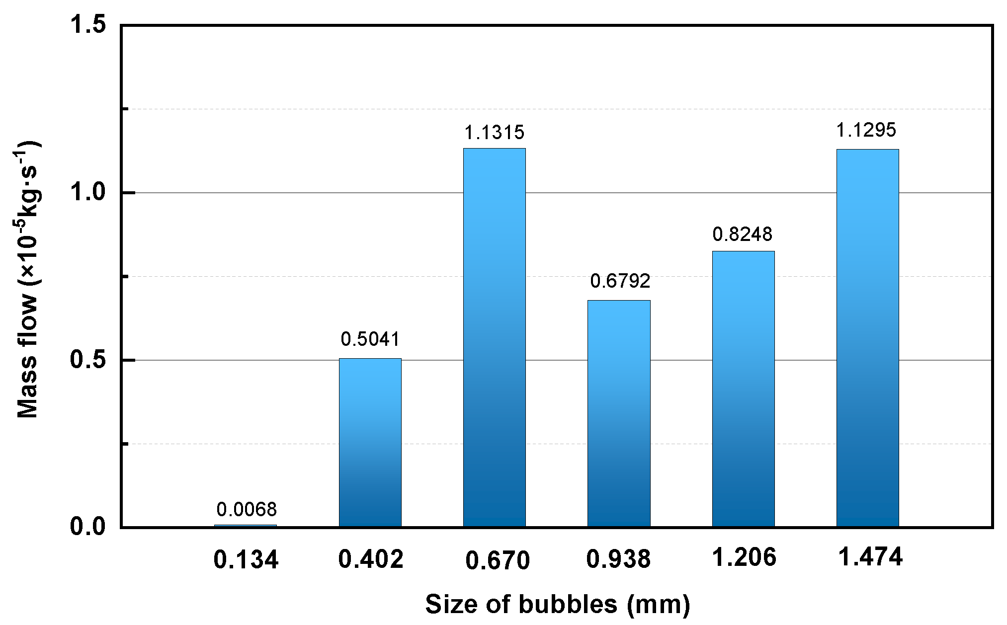
In order to further investigate the motion behaviors of bubbles in liquid steel of the tundish, which largely influences the removal effect of inclusions, the two-phase flow of liquid steel and argon gas in the tundish was simulated based on the actual continuous casting process. According to the above analysis of bubble size, the varied sizes of bubbles in the simulation were discretely set as 0.134, 0.402, 0.670, 0.938, 1.206, and 1.474 mm, and the mass flow of bubbles with varied sizes was calculated and shown in Figure 8.
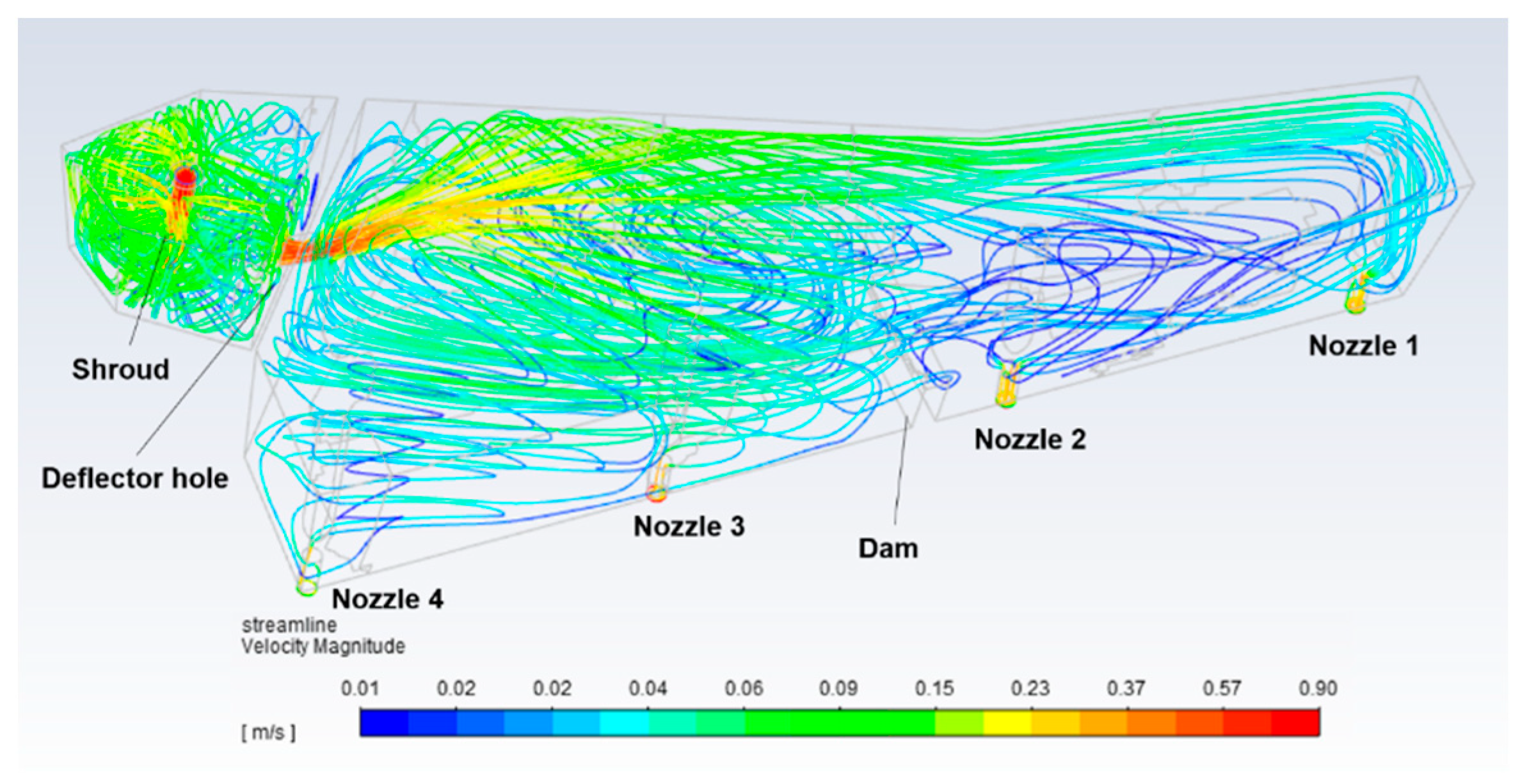
Figure 9 shows the streamline of liquid steel in the tundish obtained by the numerical simulation. The flow rate of liquid steel was relatively large at the outlet of the shroud, and part of liquid steel shot downwards into the bottom of impact zone and spread around. The turbulent streamline of liquid steel could be found at the impact zone because this zone was narrow and close to the outlet of the shroud. Liquid steel entered the casting zone through the deflector hole of the wall. Guided by the slope angle of the deflector hole, liquid steel first flowed to the liquid surface and then gradually spread. The tundish was divided into two parts by placing a dam. Part of the liquid steel blocked by the dam moved to the left side of the tundish and flowed into Nozzles 3 and 4; the rest crossing the dam moved to the right side and flowed in to Nozzles 1 and 2.
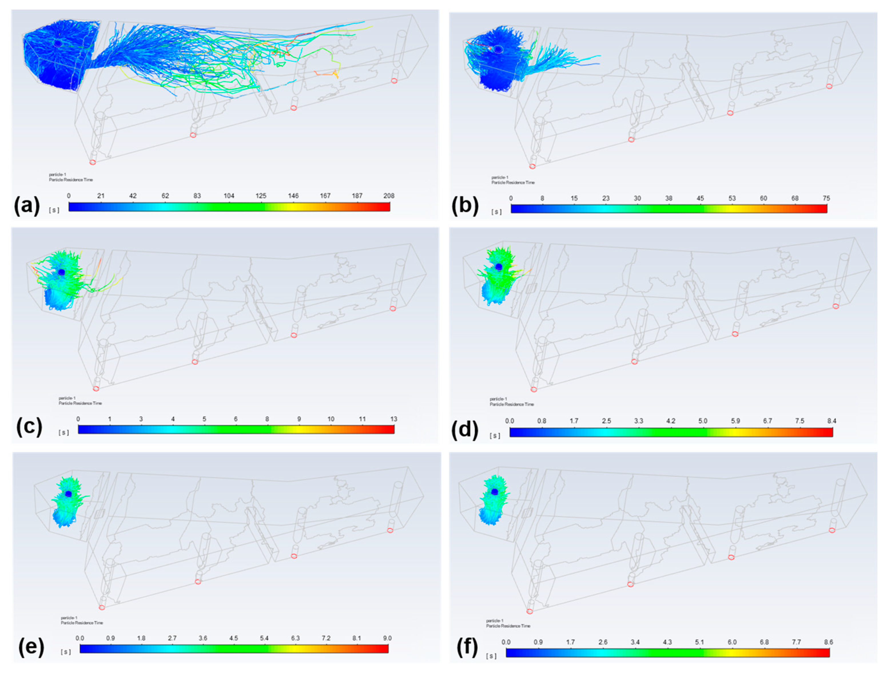
Bubbles are likely to move with the turbulent liquid steel flow, and this trend can be stronger if the size of bubbles is smaller or the flow rate of liquid steel is larger. However, the flow rate of liquid steel in the tundish is extremely uneven. When the flow rate of liquid steel decreases, bubbles may gradually float up due to the effect of buoyancy and deviate away from the flow of liquid steel. Figure 10 shows the motion trace and residence time of bubbles at different sizes moving along with liquid steel by the numerical simulation. As shown in Figure 10a, bubbles with a diameter of 0.134 mm strongly tended to move along with liquid steel, and part of the bubbles widely distributed in the casting zone. These small-size bubbles followed the flow of liquid steel under the action of drag force and had a relatively long residence time in the tundish, with a maximum of 200 s. As shown in Figure 10b–e, when the size of bubbles increased, the motion range of bubbles progressively narrowed while the residence time of bubbles obviously shortened in the tundish. When the diameter of bubbles increased to 0.938 mm, all the bubbles floated up at the impact zone, and the maximum residence time reduced to 8 s.
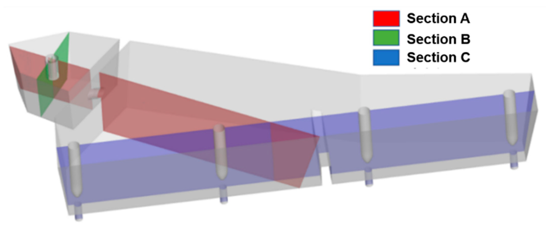
Three characteristic cross-sections were selected to further describe the distribution behavior of bubbles at different sizes in the tundish. As shown in Figure 11, the three characteristic cross-sections were Section A at the centers of the ladle shroud and deflector hole, Section B perpendicular to Section A at the center of the ladle shroud, and Section C through the centers of four nozzles.
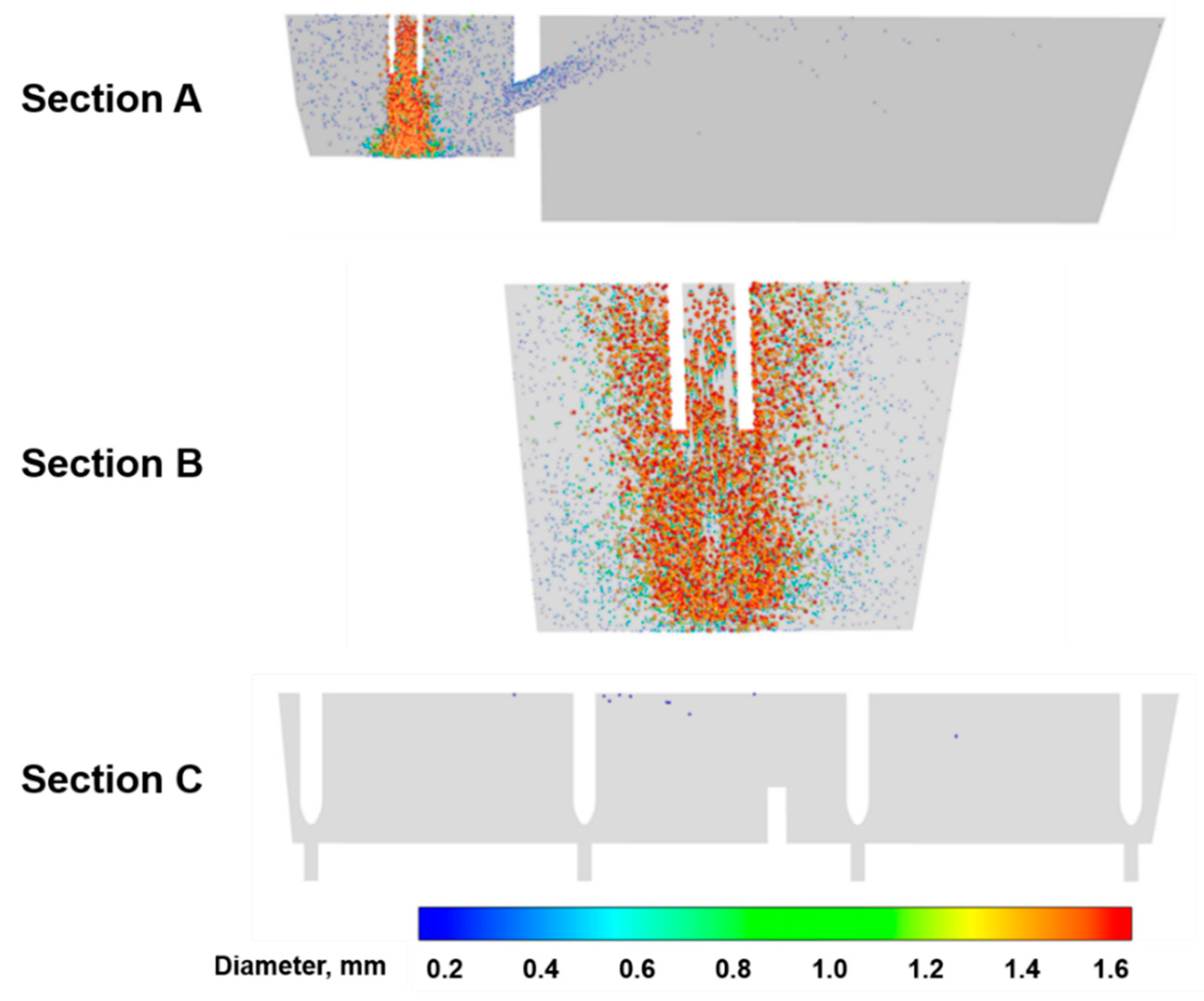
Figure 12 shows the distribution of bubbles at the three characteristic cross-sections. For bubbles with a diameter less than 0.938 mm, they mainly distributed at the impact zone, but a small proportion of them could still pass through the deflector hole of the wall to reach the casting zone by following the flow of liquid steel. The deflector hole made the bubbles move to the surface of liquid steel, and only bubbles with a diameter of 0.134 mm would flow downwards to the dam and then float up. By contrast, the distribution of bubbles with a diameter lager than 0.938 mm narrowed to the zone near the ladle shroud. Since these large-size bubbles were little affected by transverse streams, they shot downwards to the bottom of the tundish and then quickly floated up, following the high-speed liquid steel. No bubbles were found near the outlets of the tundish, indicating that the fine bubbles generated by (AIILS) will not go into the mold through the outlets.
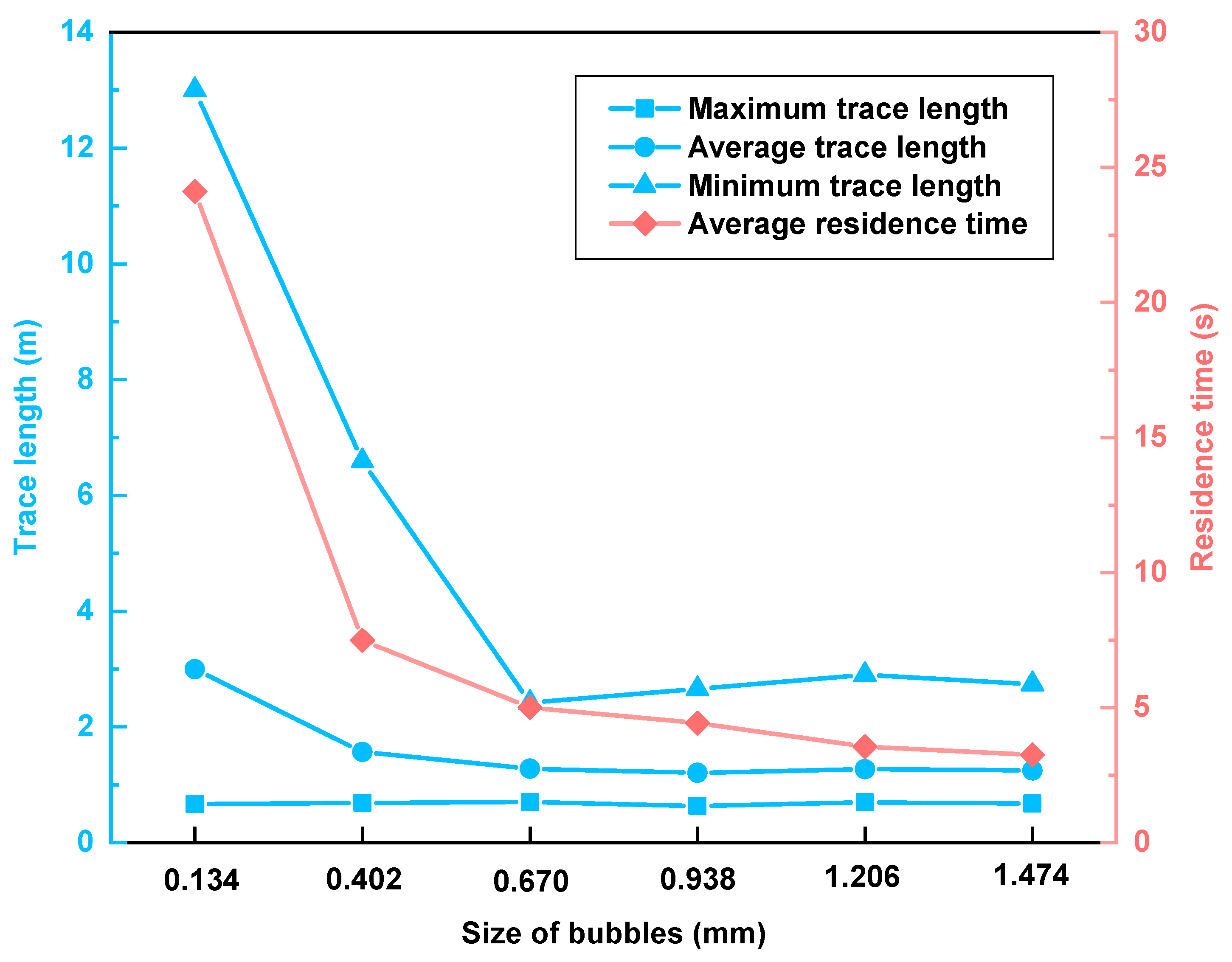
Figure 13 shows the statistics results of motion trace and residence time for bubbles at different sizes. The average residence time and the trace length of bubbles were almost in inverse proportion to diameter. When the diameter of bubbles increased from 0.134 mm to 0.670 mm, the average residence time reduced from 24 s to 5 s, the maximum trace length from 13 m to 2.5 m, and the average trace length from 3 m to 1 m. For bubbles with a diameter between 0.938 and 1.742 mm, their residence time and trace length had small variation with diameter due to their nearly identical motion trace. Moreover, the minimum trace length of bubbles stayed almost constant with diameter, which indicated that bubbles at different sizes could directly float up with liquid steel after leaving the ladle shroud.
Bubbles can absorb inclusions during their motion to improve the cleanness of liquid steel. Thus, a larger filtration volume of bubbles will increase the possibility of collision and adherence between bubbles and inclusions. The filtration volume of bubbles V i was expressed as follows:
V i = S i × L i
where S i is the cross-section area of bubbles, m2; L i is the trace length of bubbles in flow field, m. Figure 14a shows the average filtration volume of bubbles at different sizes. Although it has been found that the trace length of bubbles was in inverse proportion to diameter, the average filtration volume still increased with the increasing diameter of bubbles. The reason for this is that there is a square relationship between their cross-section area and diameter for bubbles, namely that the devotion of cross-section area to the variation rate of filtration volume is larger than that of trace length. The gas flow rate was set as 3.0 m3·h−1 in this simulation, and there were approximately 3.1 × 10⁵ bubbles entering the flow field per second. The filtration rate was introduced to express the filtration volume of bubbles per second. The filtration rate of bubbles at different sizes is shown in Figure 14b. Compared with bubbles of other sizes, bubbles with a diameter of 0.670 mm had the largest filtration rate of 0.03 m3·s−1 under the simulation conditions of this study. In terms of all the bubbles generated at an argon-blowing rate of 3.0 m3·h−1, the total filtration volume per second in the tundish was about 0.12 m3, which is 44% of the volume of the impact zone. Thus, bubbles in the size range of our investigation have a large enough filtration rate to have a good performance on inclusion removal.

3.3. Inclusion Removal by Bubbles

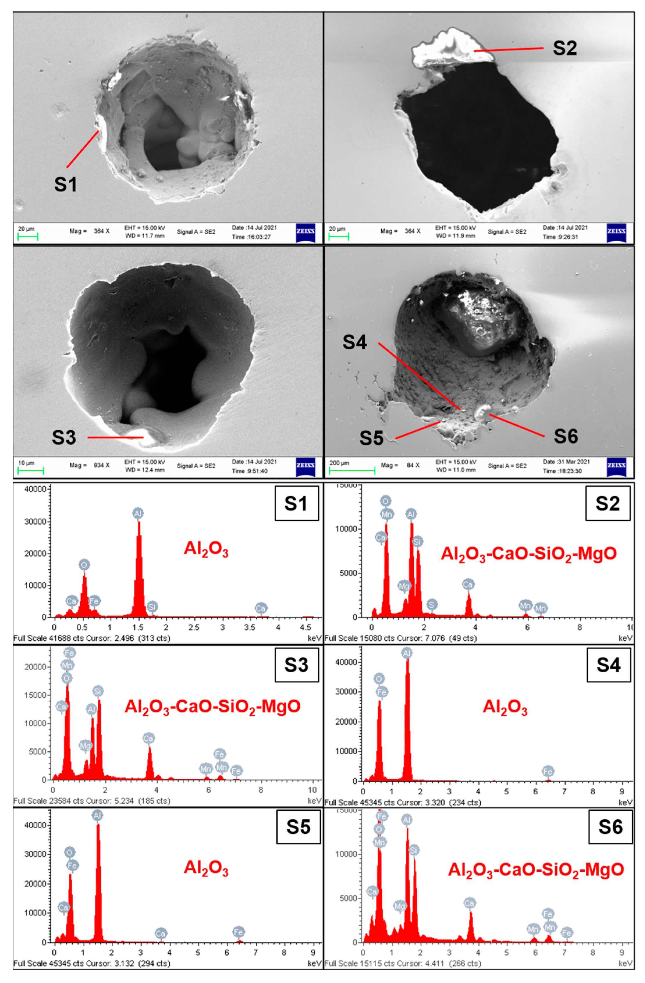
Finely dispersed bubbles can collide with inclusions in liquid steel of the tundish and promote inclusions to float up and be removed by the top slag. Figure 15 shows the SEM images and EDS results of inclusions adhering to bubbles. The types of inclusions mainly included Al2O3, Al2O3-CaO-SiO2, and Al2O3-CaO-SiO2-MgO. Most of the bubbles had one inclusion on their surface, but it was also found that a small proportion of bubbles could absorb several inclusions. The statistics results showed that bubbles were more likely to absorb Al2O3 inclusions due to the large wetting angle between them.
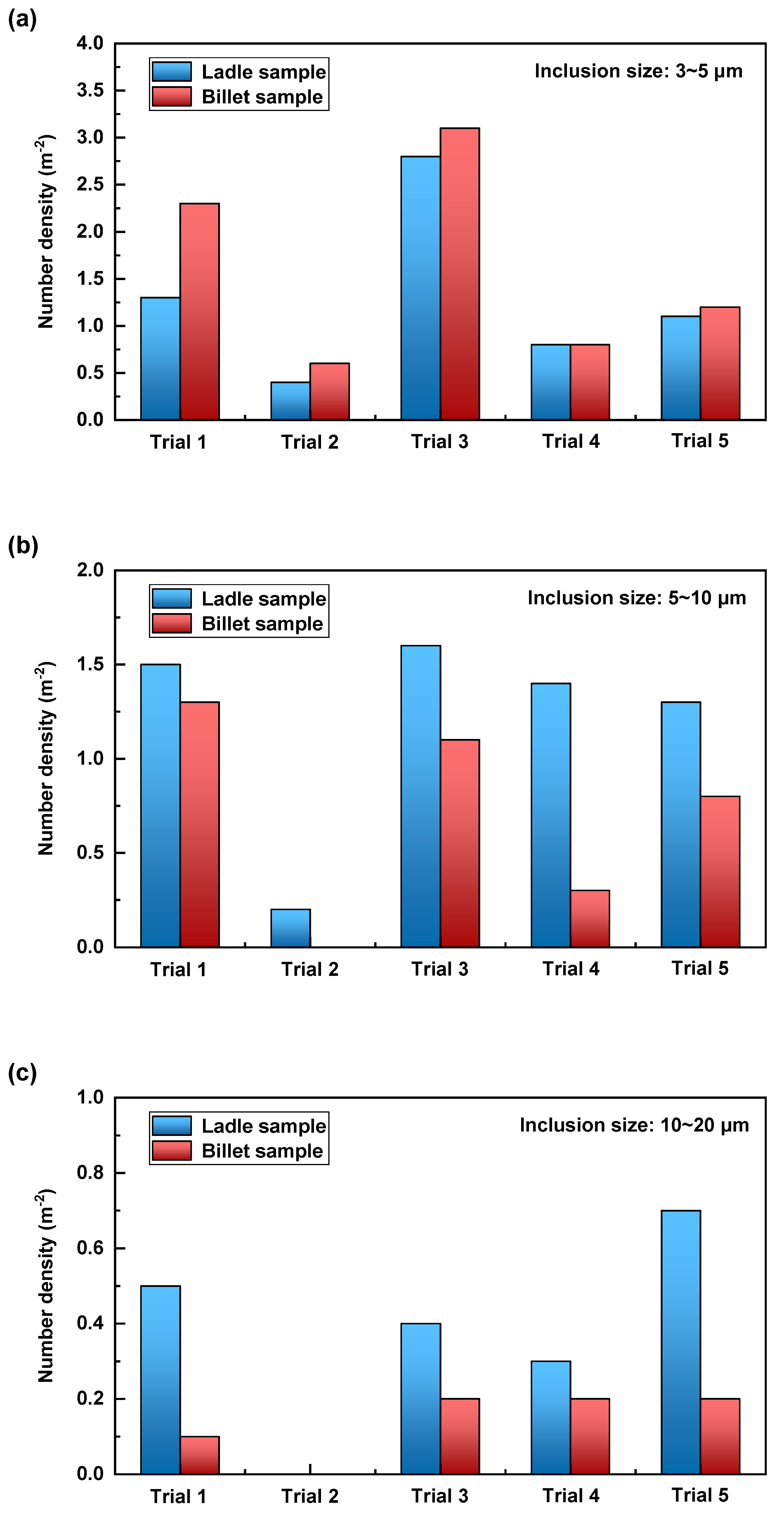
The inclusions in steel samples taken from the ladle and casting billet were compared to evaluate the effect of AIILS on inclusion removal occurring in the tundish. Figure 16 shows the number density of inclusions of different sizes in steel samples taken from the ladle and casting billet for the five industrial trials with different argon-blowing rates. It could be found that the tundish itself had a good capability of removing large-size inclusions, especially those with a diameter larger than 10 μm. The implementation of AIILS obviously promoted the removal of inclusions with a diameter between 5 and 10 μm, although it had no distinct effect on those with a diameter less than 5 μm. Specifically, Trial 1 without argon blowing had a removal rate of 14.19% for inclusions with a diameter between 5 and 10 μm, while the removal rates of the other four industrial trials with AIILS increased to 100%, 29.30%, 80.42%, and 41.35%, respectively, with an average increment of 48.58%. It shows that the method of AIILS can further improve the removal of inclusions with a diameter between 5 and 10 μm on the basis of the tundish. However, there was no obvious trend that a higher argon-blowing rate would have a better removal rate of inclusions. On the one hand, this might be due to the fluctuation of industrial conditions; on the other hand, the variation of argon-blowing rates of this study might not have an essential effect on the size, number, and distribution of bubbles formed by AIILS.
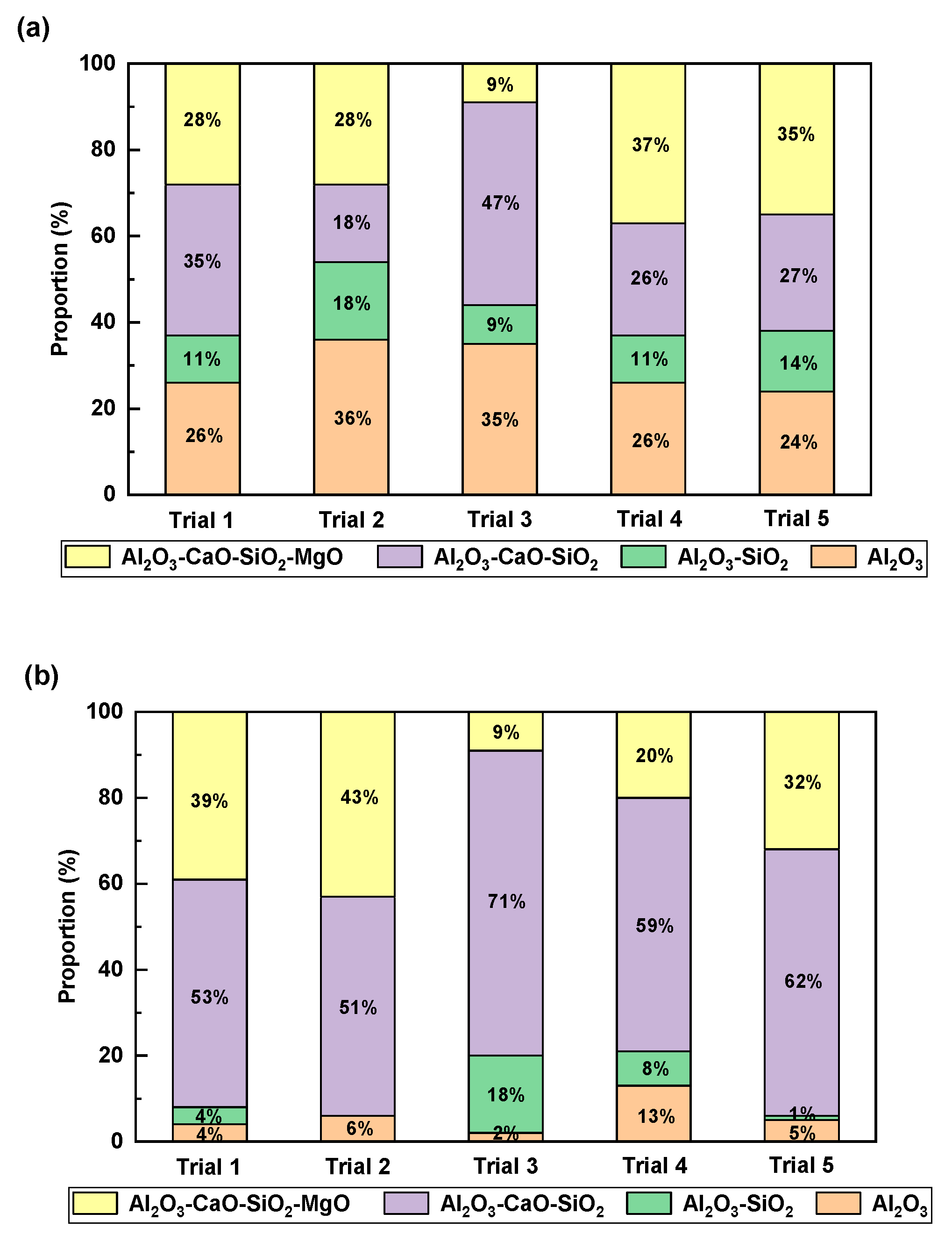
Figure 17 shows the comparison of inclusion types in steel samples taken from the ladle and casting billet for the five industrial trials with different argon-blowing rates. The proportions of Al2O3 inclusions in the steel samples from the ladle were in the range of 24 to 36%, while those from the casting billet were below 13%. As mentioned above, Al2O3 inclusions were removed by floating up with the rising bubbles more easily due to the large wetting angle.
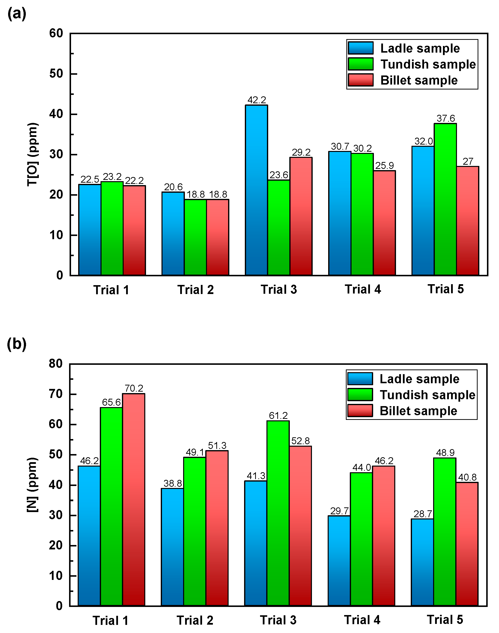
Furthermore, the variations of O and N contents in steel samples taken from the ladle, tundish, and casting billet were compared to reflect the change of oxide inclusions in steels and to judge the degree of secondary oxidation during the casting process. Figure 18a shows the variations of total O content (T[O]) in steel samples taken from the ladle, tundish, and casting billet for the five industrial trials with different argon-blowing rates. After the implementation of AIILS, the removal rates of T[O] had an overall improvement, with an increase of 6.0 to 28.91% compared with Trial 1 without argon blowing. Particularly, the improvement effect of Trial 3 was the largest. It is mostly because the ladle sample of Trial 3 had the highest T[O], and thus there should be more room for oxygen removal for Trial 3. The result indicates that the method of AIILS can effectively reduce T[O] in steels and improve steel cleanliness. Figure 18b shows the variations of N content in steel samples taken from the ladle, tundish, and casting billet for the five industrial trials with different argon-blowing rates. For Trial 1 without argon blowing, the N content in the steel sample from the casting billet increased by 24 ppm compared with that from the ladle. However, the increments of N content during the casting process for Trials 2 to 5 were 12, 12, 16, and 12 ppm, with an average of 13 ppm. The obvious decrease in the increments of N during the casting process indicates that the implementation of AIILS can reduce secondary oxidation and effectively improve the protective casting. Moreover, some research works showed that an exorbitant argon-blowing rate might cause the formation of slag “eye” and thus intensify the secondary oxidation of liquid steel. Within the argon flowing rate range of this study, the increment of N content stayed stable as the argon-blowing rate increased. This suggests that under the experimental conditions of this study, the implementation of higher argon-blowing rates will not reduce the effect of protective casting.

4. Conclusions

Bubbles in actual liquid steel of the tundish were successfully captured, relying on the method of “cold steel plate dipping”. Finely dispersed bubbles with diameters in the range of 100 to 1000 μm were generated in the tundish under the implementation of AIILS. The number of bubbles at the upper portion of impact zone of the tundish was relatively greater compared with the lower portion. According to the ICT inspection, the average diameter of bubbles generated by AIILS was around 500 μm under the conditions of this study.
The two-phase flow of liquid steel and argon gas in the tundish was simulated based on the actual continuous casting process. Small-size bubbles were more likely to follow the flow of liquid steel under the action of drag force and had a relatively long residence time in the tundish. The average residence time and the trace length of bubbles were in inverse proportion to their diameters. Bubbles in the size range of this investigation were expected to have a good performance on inclusion removal due to the large filtration rate of liquid steel in the tundish.
Bubbles were observed to absorb one or several inclusions on their surface. The type of inclusions included Al2O3, Al2O3-CaO-SiO2, and Al2O3-CaO-SiO2-MgO. The method of AIILS was more effective at improving the removal of inclusions in the size range of 5 to 10 μm, and obviously increased the removal rate of total O content. Meanwhile, the increment of N during the continuous casting process decreased after the implementation of AIILS.

Author Contributions

Conceptualization, Y.H. and J.L.; methodology, Y.H. and J.L.; software, Y.P. and D.W.; formal analysis, Y.H., X.S. and W.L.; investigation, X.S. and W.L.; writing—original draft preparation, Y.H.; writing—review and editing, Y.H. and J.L.; visualization, W.L. and Y.P. All authors have read and agreed to the published version of the manuscript.

Funding

This research was funded by the National Natural Science Foundation of China (Grant No. 52174292) and the Major Special Science and Technology Project of Anhui Province (Grant No. 202003a07020001).

Data Availability Statement

Data are contained within the article.

Conflicts of Interest

The authors declare no conflict of interest.

References

  1. Holzinger, G.; Thumfart, M. Flow interaction in continuous casting tundish due to bubble curtain operation. Steel Res. Int. 2019, 90, 1800642. [Google Scholar] [CrossRef]
  2. Souza, G.M.; Mendonça, A.F.G.; Tavares, R.P. Physical and mathematical modeling of inclusion behavior in a tundish with gas curtain. REM Int. Eng. J. 2020, 73, 531–538. [Google Scholar] [CrossRef]
  3. Sheng, D.Y. Mathematical Modelling of Multiphase Flow and Inclusion Behavior in a Single-Strand Tundish. Metals 2020, 10, 1213. [Google Scholar] [CrossRef]
  4. Xue, Z.L.; Wang, Y.F.; Wang, L.T.; Li, Z.B.; Zhang, J.W. Inclusion removal from molten steel by attachment small bubbles. Acta Metall. Sin. 2003, 39, 431–434. [Google Scholar]
  5. Rogler, J.P.; Heaslip, L.J.; Mehrvar, M. Physical modelling of inclusion removal in a tundish by gas bubbling. Can. Metall. Quart. 2005, 44, 357–368. [Google Scholar] [CrossRef]
  6. Zhang, J.; He, Y.; Liu, J.H.; Yan, B.J.; Zhang, S.; Li, W. The effects of soluble gas floatation technology on the flow filed of ladle and inclusion removal in RH refine process. Vacuum 2019, 168, 108803. [Google Scholar] [CrossRef]
  7. Zhang, J.; Yan, B.J.; Liu, J.H.; He, Y.; Li, W.; Liu, H.B. Water model study of the removal effect of soluble gas floatation technology (SGFT) on inclusions with different characteristics. Vacuum 2021, 186, 110050. [Google Scholar] [CrossRef]
  8. Zhang, S.; Liu, J.H.; He, Y.; Zhou, C.H.; Yuan, B.H.; MacLean, A. Bubble formation by argon injection through the down-leg snorkel with Ruhrstahl-Heraeus (RH) circulating flow. J. Mater. Process. Tech. 2022, 306, 117647. [Google Scholar] [CrossRef]
  9. Yang, X.F.; Chang, W.J.; Zhong, L.C.; Li, X.X.; Ji, W.Y.; Hao, P.F. Experiment of bubble behavior in argon blowing through long shroud of continuous casting. Steelmaking 2018, 34, 12–18. [Google Scholar]
  10. Mazumdar, D.; Singh, P.K.; Tiwari, R.K. Shrouded transfer of molten steel from ladle to tundish: Current understanding, mathematical modelling and new insight. ISIJ Int. 2018, 58, 1545–1547. [Google Scholar] [CrossRef] [Green Version]
  11. Wang, L.; Lee, H.G.; Hayes, P. A new approach to molten steel refining using fine gas bubbles. ISIJ Int. 1996, 36, 17–24. [Google Scholar] [CrossRef] [Green Version]
  12. Zhang, Q.Y.; Wang, L.T.; Xu, Z.R. A new method of removing inclusions in molten steel by injecting gas from the shroud. ISIJ Int. 2006, 46, 1177–1182. [Google Scholar] [CrossRef] [Green Version]
  13. Li, J.; Wen, G.; Zhu, M.M.; Tang, P. A new application of turbulator in removing inclusions by injecting gas from the shroud. Metal. Int. 2012, 17, 57–62. [Google Scholar]
  14. Fan, A.Y.; Wen, G.H.; Li, J.X.; Tang, P. Present situation and prospect of fine gas bubbles formation in the ladle shroud. Steelmaking 2015, 32, 67–72. [Google Scholar]
  15. Chang, S.; Cao, X.E.; Zou, Z.S.; Isac, M.; Guthrie, R.I.L. Microbubble swarms in a full-scale water model tundish. Metall. Mater. Trans. B 2016, 47, 2732–2743. [Google Scholar] [CrossRef]
  16. Bao, Y.P.; Liu, J.H.; Xu, B.M. Behaviors of fine bubbles in the shroud nozzle of ladle and tundish. Int. J. Min. Met. Mater. 2003, 10, 20–23. [Google Scholar]
  17. Singh, P.K.; Mazumdar, D.A. Physical model study of two-phase gas-liquid flows in a ladle shroud. Metall. Mater. Trans. B 2018, 49, 1945–1962. [Google Scholar] [CrossRef]
  18. Chatterjee, S.; Chattopadhyay, K. Physical modeling of slag ‘eye’ in an inert gas-shrouded tundish using dimensional analysis. Metall. Mater. Trans. B 2016, 47, 508–521. [Google Scholar] [CrossRef]
  19. Chattopadhyay, K.; Isac, M.; Guthrie, R.I.L. Physical and mathematical modelling of inert gas shrouding in a tundish. ISIJ Int. 2011, 51, 573–580. [Google Scholar] [CrossRef] [Green Version]
  20. Chatterjee, S.; Chattopadhyay, K. Formation of slag “eye” in an inert gas shrouded tundish. ISIJ Int. 2015, 55, 1416–1424. [Google Scholar] [CrossRef] [Green Version]
  21. Liu, J.H.; Li, W.; He, Y.; Su, X.F.; Zhang, J.; Chang, F.R. Industrial experimental study on the formation of microbubbles by argon injection into ladle shroud. Chin. J. Eng. 2022, 44, 1183–1191. [Google Scholar]
  22. Launder, B.E.; Spalding, D.B. The numerical computation of turbulent flows. Comput. Method. Appl. M. 1974, 3, 269–289. [Google Scholar] [CrossRef]
  23. Merder, T.; Warzecha, M. Optimization of a six-strand continuous casting tundish: Industrial measurements and numerical investigation of the tundish modifications. Metall. Mater. Trans. B 2012, 43, 856–868. [Google Scholar] [CrossRef] [Green Version]
  24. Bai, H.; Thomas, B.G. Bubble formation during horizontal gas injection into downward-flowing liquid. Metall. Mater. Trans. B 2001, 32, 1143–1159. [Google Scholar] [CrossRef]
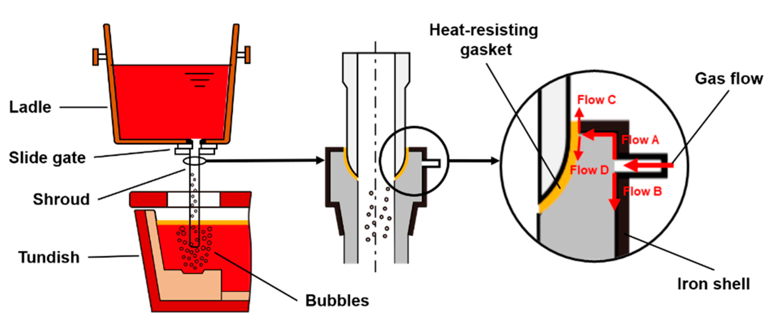
Figure 1. Schematic diagram of protective casting using AIILS.
Metals 13 00593 g001
Figure 2. Sampler used for the method of “cold steel plate dipping”.
Metals 13 00593 g002
Figure 3. Sampler before and after dipping into liquid steel.
Metals 13 00593 g003
Figure 4. Computational domain of the tundish for numerical simulation.
Metals 13 00593 g004
Figure 5. LSM images of bubble distribution at different depths of the tundish: (a) upper, (b) middle, and (c) lower portions for Trial 3 with an argon-blowing rate of 3.0 Nm3·h−1; (d) upper, (e) middle, and (f) lower portions for Trial 4 with an argon-blowing rate of 5.0 Nm3·h−1.
Metals 13 00593 g005
Figure 6. SEM images of bubbles captured in liquid steel of the tundish.
Metals 13 00593 g006
Figure 7. Three-dimensional morphology of bubbles inside the steel sample using ICT: (a) sample 1; (b) sample 2.
Metals 13 00593 g007
Figure 8. Mass flow of bubbles with varied sizes in the numerical simulation.
Metals 13 00593 g008
Figure 9. Streamline of liquid steel in the tundish obtained by the numerical simulation.
Metals 13 00593 g009
Figure 10. Motion trace and residence time of bubbles at different sizes: (a) 0.134, (b) 0.402, (c) 0.670, (d) 0.938, (e) 1.206, and (f) 1.474 mm.
Metals 13 00593 g010
Figure 11. Diagrammatic sketch of three characteristic cross-sections in the tundish.
Metals 13 00593 g011
Figure 12. Distribution of bubbles at the three characteristic cross-sections.
Metals 13 00593 g012
Figure 13. Statistics results of motion trace and residence time for bubbles at different sizes.
Metals 13 00593 g013
Figure 14. (a) Average filtration volume and (b) filtration rate of bubbles at different sizes.
Metals 13 00593 g014
Figure 15. SEM images and EDS results of inclusions adhering to bubbles.
Metals 13 00593 g015
Figure 16. Number density of inclusions of different sizes in steel samples taken from ladle and casting billet for the five industrial trials: (a) 3–5 μm; (b) 5–10 μm; (c) 10–20 μm.
Metals 13 00593 g016
Figure 17. Comparison of inclusion types in steel samples taken from (a) ladle and (b) casting billet for the five industrial trials.
Metals 13 00593 g017
Figure 18. Variations of (a) total O content and (b) N content in steel samples taken from ladle, tundish, and casting billet for the five industrial trials.
Metals 13 00593 g018
Table 1. Recommended constant values in the standard k-ε turbulence model.
C1C2Cμσεσk
1.441.920.091.31.0
Disclaimer/Publisher’s Note: The statements, opinions and data contained in all publications are solely those of the individual author(s) and contributor(s) and not of MDPI and/or the editor(s). MDPI and/or the editor(s) disclaim responsibility for any injury to people or property resulting from any ideas, methods, instructions or products referred to in the content.