Article

Surface Evolution of Vermicular Cast Iron in High Frequent Cyclic Plasma and Different Facial Cooling Airflows

School of Materials and Chemical Engineering, Xi’an Technological University, Xi’an 710021, China
*
Author to whom correspondence should be addressed.
Metals 2023, 13(3), 577; https://doi.org/10.3390/met13030577
Submission received: 10 February 2023 / Revised: 28 February 2023 / Accepted: 8 March 2023 / Published: 13 March 2023
(This article belongs to the Special Issue Recent Advances in Cast Irons)

Abstract

:
The surface evolution of vermicular cast iron in a high frequent cyclic plasma and facial cooling airflow was studied to understand the behavior and mechanism in different cooling conditions under a unique thermal shock environment. Results indicated that both the mass and linear loss presented titled inverted V-shaped relationships with the flux of the cooling airflow, while the change in roughness decreased continuously. As the cooling airflow rose, the eroded zone was reduced, the iron oxides lessened, and fluctuation of the surface temperature weakened. In combination with the thermodynamic calculations and thermal analysis, it was confirmed that the oxidation and mechanical erosion had contrary tendencies with the rising flux in the facial cooling airflow. The transformation of the dominant factor from oxidation to peeling off by thermal stress and scouring resulted in the evolution of mass and thickness. The surface oxides dominated the change in the roughness.

1. Introduction

Vermicular cast iron (RuT), also named compacted cast iron, has both the advantages of gray and nodular cast irons. The outstanding casting performance and good combination of mechanical and thermal properties have made RuT a perfect material for the cylinder head and blocks of a high power density (HPD) diesel engine [1,2,3]. Furthermore, the RuT has also received increasing attention on the application for a heavy truck brake system [4].
In a HPD diesel engine, as a key power of large machinery and transportation tool, the cylinder block or cylinder head material will be damaged by the high frequent impact of high temperature and high pressure generated by the detonation of flame. Due to its unique working environment, it is required that the high temperature components in the diesel engine must be able to withstand severe cyclic mechanical and thermal load throughout its service life. With the continuous development in the performance of a diesel engine, its working conditions become more and more severe, which results in higher and higher requirements on the comprehensive performance of RuT.
To improve the mechanical, anti-wear, and thermal properties of RuT, alloying [5,6], heat treatment [7,8], process, and surface modification [9,10] were all greatly studied. The nanoparticles were also used to adjust the microstructure [4]. Among these works, more and more attention have focused on surface treatment since many failures originated from there. Methods such as atmospheric plasma spraying [10], plasma transfer arc cladding [11], laser cladding [12], laser melt injection [13], diffusion thermo-reactive treatment [14], and some others have all been performed to optimize the surface for an improvement in the properties. Meanwhile, many studies such as thermal exposure [15], oxidation [16,17], creep [18,19], thermal shock [20], thermal fatigue [21,22], and thermal-mechanical fatigue [23,24,25] have focused on the high temperature performances and failure mechanism of the RuT to understand the practical problems of relative components. Great efforts have been made from the perspective of mechanics. Qiu et al. [15] mainly studied the effect of thermal exposure conditions on the in situ tensile fracture behavior. With the increase in the thermal exposure time, the strength of the compacted graphite cast iron decreased, but the elongation at break increased. Guo et al. [16,17] analyzed the high temperature oxidation behavior of vermicular cast iron with different vermicular graphite rates and found that the oxidation weight gain decreased rapidly with the decrease in the vermicular graphite rate. Meanwhile, graphite was the core and channel of oxidation. The pearlite in the vermicular cast iron was oxidized and decomposed into ferrite and cementite at high temperature. Wu and Jing et al. [18,19] found that when the ratio of test temperature to melting temperature was greater than 0.5 and the load was higher than 150 MPa, obvious creep deformation would occur. In addition, creep damage was easy to occur in compacted graphite cast iron under wide temperature and stress conditions. Combined with the multi-objective optimization method, the creep constitutive model was constructed. Wang et al. [20] studied the oxidation and thermal cracking behavior under a high temperature and thermal shock environment, and found that graphite on the surface oxide scale was beneficial to the formation of surface thermal cracks. In addition, it can be inferred that the path of hot crack propagation along the thickness direction was the graphite-oxide network. Zhang et al. [22] studied two different types of compacted cast iron, and found that the ferrite grain boundary sliding temperature and pearlite transition temperature had an important influence on the thermal fatigue cracks of the two materials. Hilbery et al. [23] found that with the increase in the average length of graphite inclusions, the thermal mechanical fatigue life decreased, and the graphite content had no effect on it. Furthermore, Norman et al. [25] studied the thermo-mechanical fatigue properties of heterogeneous compacted cast iron at different maximum temperatures and mechanical strain ranges, and found that the micro-cracks independently expanded from fatigue to the rapid connection point of the cracks, resulting in final failure. Some other investigations found that thermal chemical reactions [26] and phase transformations [27] were also important to the failure of the diesel engine cylinder head. Some oxides could promote the crack propagation.
In the working condition of a cylinder head in a HPD diesel engine, the combustion and mixed air–oil have an impact on the RuT at high frequency. Obviously, this is different from the widely studied static oxidation, normal thermal shock, or thermal fatigue in the laboratory. However, few studies can be found on the evolution of RuT in a unique thermal shock environment, which has limited both the optimization of materials and structure. Referring to the large number of studies of flame tests for aerospace applications [28,29,30], some bench tests have recently been performed to simulate the working condition [31,32,33,34]. In our previous work, RuT [35], piston Al alloy [36], and modified C/C composites [37] were studied in the high frequent cyclic impact of combustion and airflow. The RuT and the others presented different erosion behavior from normal oxidation and thermal shock.
With the development of the diesel engine, key components possessing high precision and low roughness are always necessary. Furthermore, keeping the precision and surface state of service stable is also important for the cylinder head since an evident change in the size or roughness is sometimes fatal. When excess oxides are peeled off from the original surface, the combustion chamber like piston will be greatly damaged, which might lead to a failure of the whole machine. Additionally, working in various climatic environments is inevitable. The RuT for the cylinder head will undergo different cooling states, resulting in various intensities of thermal shock and surface damage. Therefore, as a following work in high frequency cyclic plasma, this study mainly dealt with the influence of facial cooling airflow on the surface erosion of RuT.

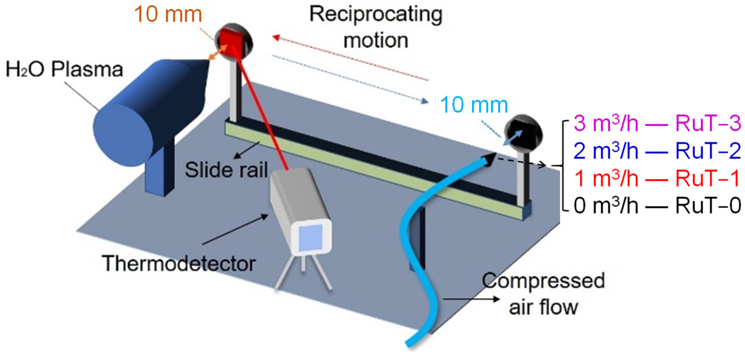
2. Materials and Methods

2.1. Preparation of the Vermicular Cast Iron

The raw materials used for the preparation of the vermicular cast iron were pig iron and 45 scrap steel. These were melted by a medium-frequency induction furnace. When the temperature reached 1300 °C, the material was completely melted, and the creeping agent and inoculant were added, respectively. The main components of the creeping agent and inoculant were 0.45~0.5 wt% Mg–Re alloy and 0.8 wt% 75Si–Fe. Then, the melt was cleaned at a temperature of about 1470 °C and poured into the sand mold through the bottom gate system. Before pouring, the quality of the fracture triangular test block should be analyzed. The following cast was carried out only when the quality met the demand. The specimen for the test was cut from the bottom of the castings when cooled to room temperature, then the specimens were machined into a wafer type of φ30 × 5 mm3. After sanding with different types of sandpaper (#80, #240, #600, #800, #1200, #1500, #2000) in order, the surface was polished by the cross method and dried for later experiments.

2.2. Tests and Characterization

As shown in Figure 1, the tested sample was cyclic impacted by plasma and cooling airflow through reciprocating motion under a 2 s period. The plasma was generated by Multiplaz 3500 using H2O as the medium. The working voltage was 160 V and the relevant current was 6 A. The cooling airflow was provided by an air compressor under a pressure of 0.4 MPa. All of the tested samples were divided into four groups according to the different facial cooling airflows. The groups in fluxes of 0, 1, 2, 3 m3/h were marked as RuT-0, RuT-1, RuT-2, and RuT-3, respectively. During the experiment, both the plasma and airflow jets were vertical to the surface of the tested sample and scoured for 0.5 s in each cycle. Both the diameters of the nozzles were 2 mm and their tips were 10 mm far from the sample surface. Moreover, the plasma was about 2300 °C at this distance, which was confirmed by a porous zirconia and an Endurance E1RH infrared thermometer (1000~3200 °C with a precision of ±0.5%). During the test, the surface temperature was real-time monitored by an Endurance E3ML infrared thermometer with a response time of 20 ms (50~1000 °C with a precision of ±0.3%). The infrared thermometer was located at about 1 m in front of the measured sample surface, forming a certain angle with the sample surface.
The mass and linear losses were calculated according to the weight changes and thickness variation of the sample center. The specific formulas are as follows:
M = (m0m1)
L = (l0l1)
where M is the mass loss and L is the linear loss; m0 and m1 are the mass of the sample before and after the test, and l0 and l1 are the thickness of the sample center before and after test. Furthermore, the change of roughness was also calculated through the roughness before the test minus that after the test. The roughness was measured by a detecting instrument (TR200) with a resolution of 0.01 μm/±20 μm. The surface roughness measurement of each specimen was carried out five times and the average value was taken.
Differential scanning calorimetry (DSC) and thermogravimetric (TGA) analysis of the vermicular cast iron was performed in air from room temperature to 1100 °C at a heating rate of 10 °C/min on a METTLER TOLEDO (Columbus, OH, USA) TGA/DSC 1 Thermal Analysis System. An optical microscope (NIKON EPIHOT3000, Tokyo, Japan) and scanning electron microscope (SEM, JSM6460) with energy dispersive spectroscopy (EDS) were used to observe the microstructure and morphology and analyze the chemical composition of the vermicular cast iron before and after the test. The phase analysis was carried out by a Shimadzu (Kyoto, Japan) X-ray diffractometer with the LabXXRD–6000 model.

3. Results and Discussion

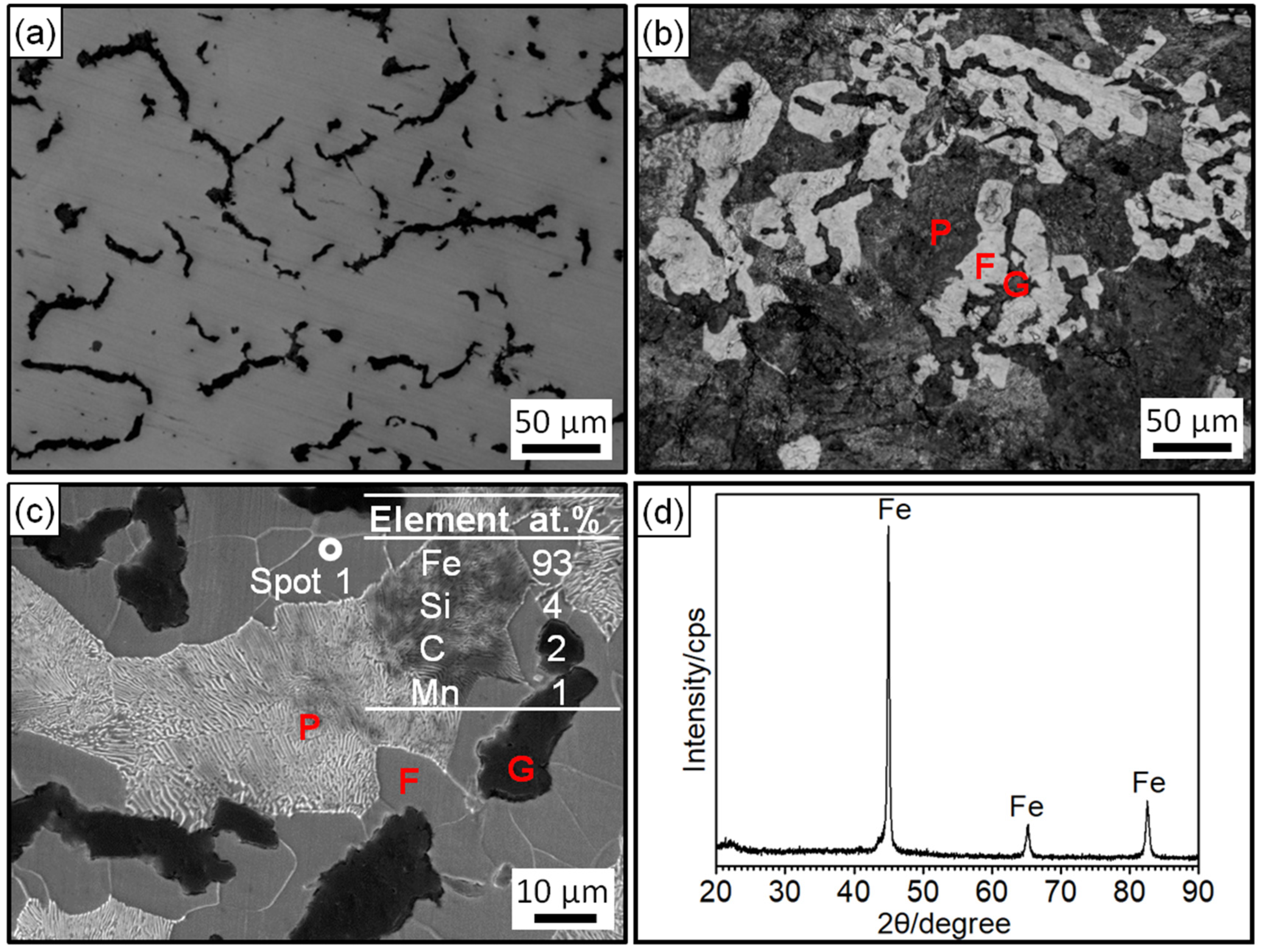
3.1. Microstructure of the Vermicular Cast Iron

Figure 2 shows the microstructure, EDS analysis, and XRD pattern of the prepared RuT. Figure 2a,b shows the morphology of the unetched and etched specimen under the optical microscope. In Figure 2a, it was obvious that two different phases existed in the vermicular cast iron. The uniformly distributed black phase should be graphite and most of the phase was worm-like. Thus, there was no doubt that the black phase was vermicular graphite. In the OM morphology after corrosion by 4 wt% nitric acid alcohol, it was found that the gray phase in Figure 2a was composed of white ferrite (F) and dark gray pearlite (P). The blunt ferrite enwrapped the vermicular graphite. Depending on the calculation by ImageJ software through three representative microscopic photographs, it was confirmed that the vermicular rate was 80~85%. Combined with the EDS results in Figure 2c and the XRD pattern in Figure 2d, the elemental composition of the vermicular cast iron was ascertained to be Fe, with a small amount of C, Si, and Mn, and some other trace elements.

3.2. Impact in High Frequency Cyclic Plasma and Facial Cooling Airflow

All of the changes in the mass, thickness, and roughness of the RuT after the test in different facial cooling airflows are displayed in Figure 3. As the flux of the cooling airflow elevated, the mass and linear loss showed similar changing rules, which increased first and then decreased, and presented titled inverted V-shaped curves. Furthermore, the values of thickness and mass losses were negative when the cooling airflow was below 1 m3/h, and became positive under a higher flux of airflow. As the airflow increased to 3 m3/h, the loss of thickness and mass were still positive but showed certain decreases. Obviously, the vermicular cast iron had a weight and thickness gain first, and then went into reverse with the rising flux in the facial cooling airflow. In contrast, the change in roughness exhibited a continuously declining trend, which should be closely related to the surface oxides.
Figure 4a shows the macroscopic photos of the RuT after the test in different facial cooling airflows. Due to the scouring of the circulating plasma and cooling airflow, different degrees of changes in the macroscopic shape of the sample came into being. It was clear that the surface center (marked by dotted circle) was heavily oxidized and had a distinct color in comparison with the surrounding region. With the increase in the flux of the cooling airflow, the region became smaller and smaller, which indicated that the heat affected zone decreased continuously. Due to the high temperature of the plasma, several oxides would be generated in the center zone since the oxidation of iron will form a variety of oxides. As presented in the XRD patterns (Figure 4b), the main composition of the tested surface comprised Fe, Fe2O3, and Fe3O4; no FeO was detected. It could be inferred that the oxides on the surface were a mixture of Fe2O3 and Fe3O4 while the Fe2O3 was greater. Furthermore, it could be seen that the intensities of both the Fe2O3 and Fe3O4 diffraction peaks declined with the strengthening of the facial cooling airflow. When the airflow rate was 3 m3/h, the Fe3O4 could not be detected and the diffraction peak of Fe2O3 was the weakest. Reconsidering the result in Figure 3, it was deduced that the oxides was the key factor of roughness, and the greater the oxides, the rougher the tested surface. When the cooling airflow worked on the surface, thermal shock was enhanced and the oxides were peeled off under scouring. As more oxides would be blown off the surface by the rising facial cooling airflow, the increases in the mass and linear losses displayed in Figure 3 were reasonable.
Figure 5 and Figure 6 exhibit the surface and cross-section morphologies of the RuT after test in the cyclic plasma and different facial cooling airflows, respectively. When the airflow was zero, the outer oxide layer could be clearly observed and the surface of the sample was uneven, as presented in Figure 5a and Figure 6a. The oxide layer gradually decreased as the airflow strengthened (Figure 5b,c and Figure 6b,c). When the flux of the airflow reached 3 m3/h (Figure 5d and Figure 6d), there was no obvious oxide layer on the surface, the oxide and matrix alloys tended to be integrated, and only some oxide particles (marked by dotted ellipse) were distributed on the tested surface. According to the EDS analysis, the outside of the oxide layer was composed of Fe2O3, which was consistent with the normal oxidation in static air. Compared with the original morphology, it was obvious that several pores were formed on the tested surface by the oxidation of graphite. These pores tended to be closed (in Figure 5a) due to the continuous expansion of these iron oxides. When the facial cooling airflow came into being, the oxidation of Fe was inhibited and the pores from the oxidized graphite became clear.
Figure 7 shows the surface temperature of the tested samples during thermal shock. All curves of the four groups first rose and then tended to stabilize. Under the condition of the gas flow rate of 0 m3/h, the temperature peak gradually increased to more than 700 °C with the rising time, and when the gas flow rate was elevated to 3 m3/h, the peak decreased to about 450 °C. In other words, the peak value of the temperature decreased continuously with the heightening of the airflow, which should result from the more consumption of heat during cooling. Furthermore, some abnormal fluctuations of the surface temperatures (indicated by green dotted circle) occurred and reduced with the rising airflow. Considering that the temperature was obtained from the radiant intensity of the surface phases, it could be deduced that some surface oxides were peeled off during test since the oxide is a decisive factor of the surface temperature for its different thermal characteristics with substrate iron. Usually, the scouring is enhanced with the increased flux of the facial airflow, and more oxides should be blown away. However, the lessened and weakened abnormal fluctuation indicated that the stripped oxides were reduced. This might be related to the decline in surface temperature and the inhibited oxidation of Fe. The change in the surface states might be the main reason for the inflection of the mass and linear losses in Figure 3.
In conclusion, after the high frequency impact of plasma and different facial cooling airflows on the vermicular cast iron, new oxides of Fe2O3 and Fe3O4 were generated on the surface compared with the original sample. With the increase in cooling airflow, the thermal eroded area reduced at a macroscopic scale. Microscopically, the amount of oxide generated on the surface of the sample decreased until no obvious oxide layer was observed. In other words, the oxide layer and the matrix alloy gradually tended to integrated under the increasing airflow, and only some oxide particles were situated at the tested surface under 3 m3/h. Meanwhile, the surface became flat. Furthermore, when the facial cooling air flow increased from 0 to 3 m3/h, the pores formed by graphite oxidation changed from closed to gradually open, the peak surface temperature of the tested surface gradually decreased, and the oxidation of iron was obviously suppressed.

3.3. Erosion Mechanism in the Thermal Shock

During thermal shock, phase transformation, thermal chemical reactions, and thermal stress always induce surface damage. In plasma, scouring by the fluid was also a key destructive factor; this scouring will have a large impact on the surface condition of the material. To understand the erosion mechanism of the vermicular cast iron in the high frequency cyclic plasma and different facial cooling airflows, how phase transformation, thermal chemical reactions, and the others work should be clarified.
Figure 8 presents the DSC/TGA thermal analysis of the RuT in air. As can be seen from the graph, the material gained weight throughout the process, which could explain that the mass and linear losses were negative when the airflow rate was low. Moreover, it can be clearly seen that an obvious weight gain occurred above 900 °C, which suggests that the oxidation below 900 °C was mild. Furthermore, there was a sudden fluctuation decrease in the curve of the heat flow at 750~800 °C, which corresponded to the phase transformation from pearlite to austenite. From Figure 7, it can be seen that all of the surface temperatures of the four tested groups were lower than 750 °C. Thus, phase transformation played a limited role in the erosion of the vermicular cast iron, and the oxides were mainly from the mild oxidation reaction.
Figure 9 shows the Gibbs free energy change curves of the possible reactions during the thermal shock process. In the case of sufficient oxygen in air, oxygen reacts with metal and graphite, corresponding to reaction Equations (3)–(6), and in the case of the scarcity of oxygen in air, the reactions of reaction Equations (7)–(10) occur.
The reaction chemical formulas are as follows:
Fe + 1/2O2 → FeO
Fe + 2/3O2 → 1/3Fe3O4
Fe + 3/4O2 → 1/2Fe2O3
C + 1/2O2 → CO
2Fe + O2 → 2FeO
3/2Fe + O2 → 1/2Fe3O4
4/3Fe + O2 → 2/3Fe2O3
C + O2 CO2
As well-known, chemical reactions can proceed spontaneously at negative Gibbs free energy change, where the smaller the Gibbs free energy value, the greater the tendency for the reaction to occur relatively. Therefore, from the Gibbs free energy change curve, it can be concluded that the dominant reaction is mainly controlled by the mass transfer of the oxidizing atmosphere on the surface. In the case of sufficient oxygen, Reaction (5) has a stronger tendency to proceed, followed by Reaction (4), so the outer surface is apt to form Fe2O3, while the sub-layer tends to generate Fe3O4. Combined with the XRD pattern, it can be determined that the oxides on the tested surface were mainly Fe2O3, which mixed with the underlying Fe3O4. Normally, the oxidation products of Fe are mainly controlled by the relative content of oxygen and the reaction temperature. At high temperature, the phases from inside to outside of the oxidized cast iron should be Fe–FeO–Fe3O4–Fe2O3. No FeO detected in this work should come from its low content or decomposition during cooling.
Figure 10 shows the schematic mechanism of the RuT surface evolution in the high frequency cyclic plasma and facial cooling airflow. Based on the above analysis, it can be inferred that the thermal chemical reactions, thermal stress, and scouring by the plasma were the main destructive factors. With an increase in the flux of the facial cooling airflow, the oxidation was reduced for the decreased heat affected zone and surface temperature. All of the morphologies in Figure 4a, Figure 5, and Figure 6 prove this. Therefore, it seems that a lower mass and linear gain are reasonable. However, the mass and linear losses showed positive values and an inflection appeared at 1 m3/h. This is because during the test, the surface damage was first caused by oxidation, and then the increase in the facial cooling airflow promoted oxide stripping under thermal stress and scouring. Therefore, when the oxidation dominated the erosion, the mass and linear losses were negative, which would become positive under stronger mechanical erosion by thermal stress and scouring. When the cooling airflow was further strengthened, even though the thermal stress and scouring ability to strip the oxide increased, less oxide was formed due to the decrease in surface temperature, which led to the peeling off being limited As a result, the mass and linear losses fell after a rise. Meanwhile, the different densities and thermal expansion behaviors between the oxides and Fe substrate resulted in a large change in roughness under thermal shock. As fewer oxides formed and were peeled off by thermal stress and scouring, it decreased and approached a stable value.

4. Conclusions

The microstructural evolution, oxidative erosion behavior, and mechanism analyses of vermicular cast iron after being subjected to high frequent cyclic plasma and different facial cooling airflows were investigated. Based on the experimental results and discussion, the following conclusions can be drawn:
(1)
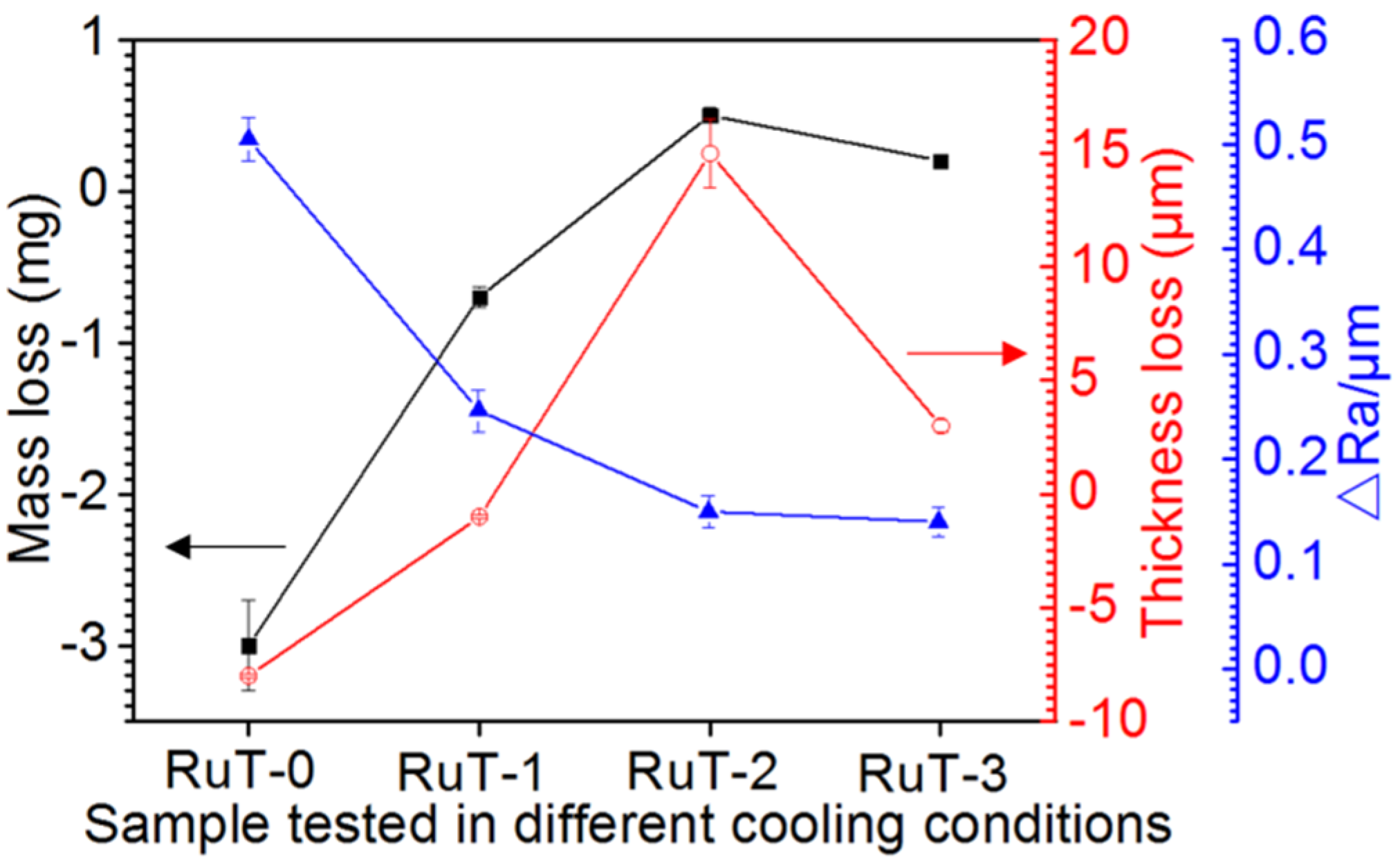
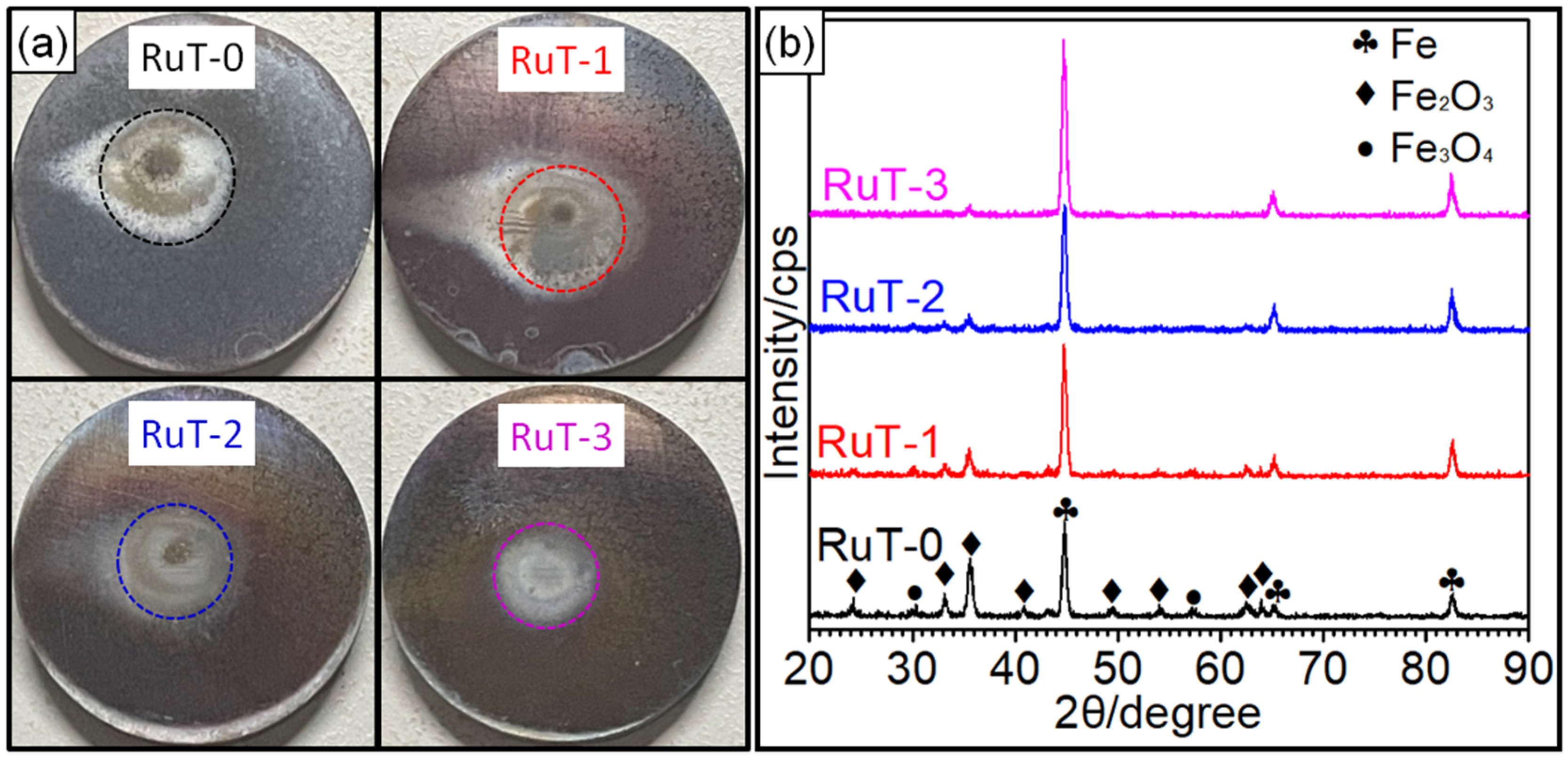
In high frequency cyclic plasma and airflow, both the mass and linear losses of the vermicular cast iron displayed titled inverted V-shaped relationships with the strengthening of facial airflow cooling, and had negative values when the flux was zero. Meanwhile, the roughness change, area of the eroded zone, and the fluctuated surface temperature decreased continuously.
(2)
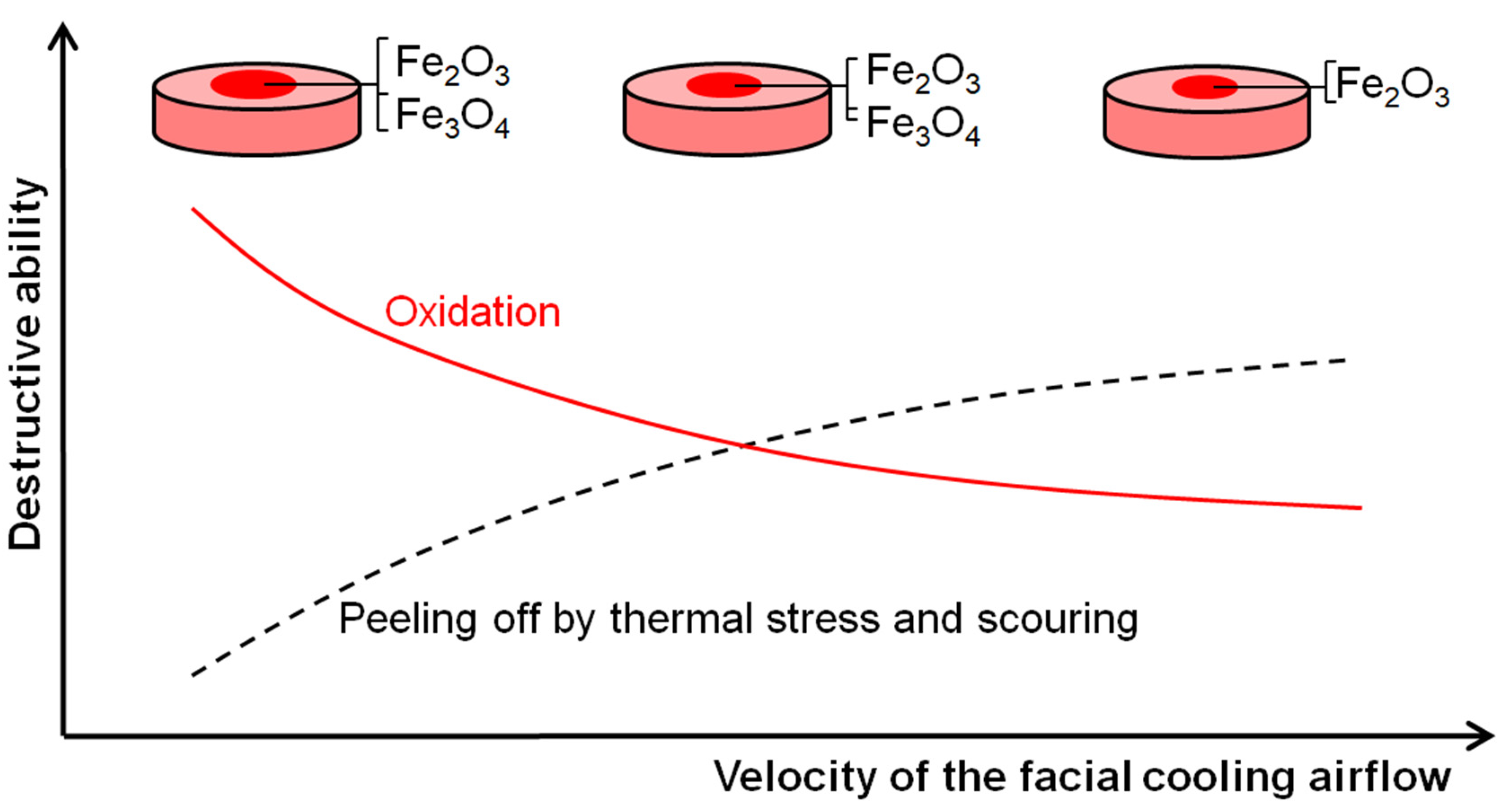
The oxidation was weakened while the peeling off by thermal stress and cooling airflow was enhanced with the rise in the flux of the facial cooling airflow. Weight gain from oxidation dominated the erosion first, and was then replaced by the peeling off, which determined the inflexion of the mass and linear losses, and the surface oxides dominated the change in the roughness.

Author Contributions

L.L.: Conceptualization, Formal analysis, Methodology, Validation, Writing-original draft; K.Z.: Data curation, Formal analysis, Writing-original draft; H.Z.: Formal analysis, Investigation, Writing-original draft; C.T. and Q.H.: Formal analysis, Writing-original draft; J.C.: Writing-review & editing; D.T.: Resources; Z.Y.: Supervision. All authors have read and agreed to the published version of the manuscript.

Funding

This research was funded by the Youth Innovation Team of Shaanxi Universities (No. 22JP031), the Natural Science Foundation of Shaanxi Province (No. 2022JQ-480), and the Innovation and Entrepreneurship Training Program for College Students (No. X202210702166).

Data Availability Statement

All data included in this study are available upon request by contacting the corresponding author.

Conflicts of Interest

The authors declare that they have no competing financial interest or personal relationship that could have appeared to influence the work reported in this paper.

References

  1. Pierce, D.; Haynes, A.; Hughes, J.; Graves, R.; Maziasz, P.; Muralidharan, G.; Shyam, A.; Wang, B.; England, R.; Daniel, C. High temperature materials for heavy duty diesel engines: Historical and future trends. Prog. Mater. Sci. 2019, 103, 109–179. [Google Scholar] [CrossRef]
  2. Liu, Y.; Li, Y.; Xing, J.; Wang, S.; Zheng, B.; Tao, D.; Li, W. Effect of graphite morphology on the tensile strength and thermal conductivity of cast iron. Mater. Charact. 2018, 144, 155–165. [Google Scholar] [CrossRef]
  3. Prasad, N.S.; Ganesh, N.; Kumarasamy, A. Technologies for high power density diesel engines. Def. Sci. J. 2017, 67, 370–374. [Google Scholar] [CrossRef] [Green Version]
  4. Wang, B.; Qiu, F.; Zhang, Y.; Yang, J.; Cui, W.; Jin, Y.; Cai, G.; Yuan, Y.; Guo, S.; Li, H.; et al. Influences of dual-phased nanoparticles on microstructure, mechanical properties and wear resistance of vermicular graphite cast iron. Mater. Lett. 2022, 308, 131296. [Google Scholar] [CrossRef]
  5. Song, L.; Guo, E.J.; Wang, L.P.; Liu, D.R. Effects of silicon on mechanical properties and fracture toughness of heavy-section ductile cast iron. Metals 2015, 5, 150–161. [Google Scholar] [CrossRef] [Green Version]
  6. Riposan, L.; Stefan, E.; Stan, S.; Pana, N.R.; Chisamera, M. Effects of inoculation on structure characteristics of high silicon ductile cast irons in thin wall castings. Metals 2020, 10, 1091. [Google Scholar] [CrossRef]
  7. Chen, Y.; Pang, J.C.; Li, S.X.; Zou, C.L.; Zhang, Z.F. Damage mechanism and fatigue strength prediction of compacted graphite iron with different microstructures. Int. J. Fatigue 2022, 164, 107126. [Google Scholar] [CrossRef]
  8. Dawson, S. Compacted graphite iron: Mechanical and physical properties for engine design. Vdi Ber. 1999, 1472, 85–106. [Google Scholar]
  9. Essam, M.A.; Shash, A.Y.; Megahed, H.; El-Kashif, E. Effect of section thickness on microstructure and mechanical properties of compacted graphite iron for diesel engine applications. Heliyon 2021, 7, e5930. [Google Scholar] [CrossRef]
  10. Gao, P.H.; Chen, B.Y.; Zeng, S.C.; Yang, Z.; Guo, Y.C.; Liang, M.X.; Xu, T.; Li, J.P. Effect of vacuum annealing on the nickel-based coatings deposited on a CGI cast iron through atmospheric plasma spraying. Metals 2020, 10, 963. [Google Scholar] [CrossRef]
  11. Sun, F.Z.; Cai, K.Q.; Li, X.X.; Pang, M. Research on laser cladding Co-based alloy on the surface of vermicular graphite cast iron. Coatings 2021, 11, 1241. [Google Scholar] [CrossRef]
  12. Mariani, F.E.; Takeya, G.S.; Lombardi, A.N.; Picone, C.A.; Casteletti, L.C. Wear and corrosion resistance of Nb-V carbide layers produced in vermicular cast iron using TRD treatments. Surf. Coat. Technol. 2020, 397, 126050. [Google Scholar] [CrossRef]
  13. Verezub, O.; Kálazi, Z.; Buza, G.; Verezub, N.V.; Kaptay, G. In-situ synthesis of a carbide reinforced steel matrix surface nanocomposite by laser melt injection technology and subsequent heat treatment. Surf. Coat. Technol. 2009, 203, 3049–3057. [Google Scholar] [CrossRef]
  14. Chen, B.; Gao, P.; Zhang, B.; Zhao, D.; Wang, W.; Jin, C.; Yang, Z.; Guo, Y.; Liang, M.; Li, J.; et al. Wear properties of iron-based alloy coatings prepared by plasma transfer arc cladding. Coatings 2022, 12, 243. [Google Scholar] [CrossRef]
  15. Qiu, Y.; Pang, J.C.; Li, S.X.; Yang, E.N.; Fu, W.Q.; Liang, M.X.; Zhang, Z.F. Influence of thermal exposure on microstructure evolution and tensile fracture behaviors of compacted graphite iron. Mat. Sci. Eng. A-Struct. 2016, 664, 75–85. [Google Scholar] [CrossRef]
  16. Guo, Q.Q.; Yang, Z.; Tao, D.; Gao, P.H.; Guo, Y.C.; Li, J.P. Effects of vermicular graphite rate on the oxidation resistance and mechanical properties of vermicular graphite iron. J. Alloy. Compd. 2018, 765, 213–220. [Google Scholar] [CrossRef]
  17. Guo, Q.Q.; Yang, Z.; Guo, D.; Tao, D.; Guo, Y.C.; Li, J.P.; Bai, Y.P. Research on the oxidation mechanism of vermicular graphite cast iron. Materials 2019, 12, 3130. [Google Scholar] [CrossRef] [Green Version]
  18. Wu, Y.; Li, J.P.; Yang, Z.; Guo, Y.C.; Ma, Z.J.; Liang, M.X.; Yang, T.; Tao, D. Creep behavior accompanying oxidation of compacted graphite cast iron. Mat. Sci. Eng. A-Struct. 2018, 723, 174–181. [Google Scholar] [CrossRef]
  19. Jing, G.X.; Li, S.B.; Chen, G.; Wei, J.C.; Sun, S.; Zhang, J.H. Research on creep test of compacted graphite cast iron and parameter identification of constitutive model under wide range of temperature and stress. Appl. Sci. 2022, 12, 5032. [Google Scholar] [CrossRef]
  20. Wang, X.S.; Zhang, W.Z. Oxidation and thermal cracking behavior of compacted graphite iron under high temperature and thermal shock. Oxid. Met. 2017, 87, 179–188. [Google Scholar] [CrossRef]
  21. Tong, X.; Zhou, H.; Ren, L.Q.; Zhang, Z.H.; Zhang, W.; Cui, R.D. Effects of graphite shape on thermal fatigue resistance of cast iron with biomimetic non-smooth surface. Int. J. Fatigue 2009, 31, 668–677. [Google Scholar] [CrossRef]
  22. Zhang, M.X.; Pang, J.C.; Meng, L.J.; Li, S.X.; Liu, Q.Y.; Jiang, A.L.; Zhang, Z.F. Study on thermal fatigue behaviors of two kinds of vermicular graphite cast irons. Mat. Sci. Eng. A-Struct. 2021, 814, 141212. [Google Scholar] [CrossRef]
  23. Kihlberg, E.; Norman, V.; Skoglund, P.; Schmidt, P.; Moverare, J. On the correlation between microstructural parameters and the thermo-mechanical fatigue performance of cast iron. Int. J. Fatigue 2021, 145, 106112. [Google Scholar] [CrossRef]
  24. Lopez, C.E.; Ghodrat, S.; Kestens, L.A. Semi in-situ observation of crack initiation in compacted graphite iron during thermos mechanical fatigue. Int. J. Fatigue 2020, 137, 105648. [Google Scholar] [CrossRef]
  25. Norman, V.; Skoglund, P.; Moverare, J. Damage evolution in compacted graphite iron during thermo-mechanical fatigue testing. Int. J. Cast. Met. Res. 2015, 29, 26–33. [Google Scholar] [CrossRef] [Green Version]
  26. Jing, G.X.; Zhang, M.X.; Qu, S.; Pang, J.C.; Fu, C.M.; Dong, C.; Li, S.X.; Xu, C.G.; Zhang, Z.F. Investigation into diesel engine cylinder head failure. Eng. Fail. Anal. 2018, 90, 36–46. [Google Scholar] [CrossRef]
  27. Palkanoglou, E.N.; Baxevanakis, K.P.; Silberschmidt, V.V. Thermal debonding of inclusions in compacted graphite iron: Effect of matrix phases. Eng. Fail. Anal. 2022, 139, 106476. [Google Scholar] [CrossRef]
  28. Ragav, P.; Panakaraju, P.; Farhan, M.; Joseph, E.R. Solid particle erosion behavior of melt-infiltrated SiC/SiC ceramic matrix composites (CMCs) in a simulated turbine engine environment. Compos. Part B-Eng. 2021, 216, 108860. [Google Scholar]
  29. Guo, J.; Fu, S.; Deng, Y.P.; Xu, X.; Laima, S.; Liu, D.Z.; Zhang, P.Y. Hypocrystalline ceramic aerogels for thermal insulation at extreme conditions. Nature 2022, 606, 909–916. [Google Scholar] [CrossRef]
  30. Yan, M.; Hu, C.; Li, J.; Zhao, R.D.; Pang, S.Y.; Liang, B.; Tang, S.F.; Liu, G.; Cheng, H.M. An unusual carbon–ceramic composite with gradients in composition and porosity delivering outstanding thermal protection performance up to 1900 °C. Adv. Funct. Mater. 2022, 32, 2204133. [Google Scholar] [CrossRef]
  31. Yan, J.H. Study on structure and ablation resistance of ceramic coating on the top of engine piston. Intern. Combust. Eng. Parts 2016, 6, 8–11. [Google Scholar]
  32. Qin, Z.J.; Jia, C.F.; Zhang, W.Z.; Wang, L.J. Investigations on ablation for highly-intensified diesel engine piston material. Case Stud. Therm. Eng. 2019, 13, 100371. [Google Scholar]
  33. Reghu, V.; Lobo, R.; Basha, K.A.; Tilleti, P.; Shankar, V.; Ramaswamy, P. Protection offered by thermal barrier coatings to Al-Si alloys at high temperatures—A microstructural investigation. Mater. Today Proc. 2019, 19, 676–681. [Google Scholar] [CrossRef]
  34. De Goes, W.U.; Markocsan, N.; Gupta, M.; Vaßen, R.; Matsushita, T.; Illkova, K. Thermal barrier coatings with novel architectures for diesel engine applications. Surf. Coat. Technol. 2020, 396, 125950. [Google Scholar] [CrossRef]
  35. Tang, C.W.; Liu, L.; Yang, Z.; Tao, D.; Li, J.P.; Guo, Q.Q.; Zhen, J.R.; He, Y.L.; He, H.X. Surface evolution of vermicular cast iron in ultra-high temperature combustion with different single-pulsing duration. Eng. Fail. Anal. 2022, 141, 106679. [Google Scholar] [CrossRef]
  36. Liu, L.; Tang, C.W.; Li, B.Y.; Li, J.P.; Bao, T.; Yang, Z.; Guo, Y.C.; Feng, W.; Lei, Z.; Li, H.Y. Surface evolution of Al-Si-Cu alloy in a high frequent pulsing oxyacetylene combustion. Case Stud. Therm. Eng. 2022, 31, 101854. [Google Scholar] [CrossRef]
  37. Liu, L.; Li, B.Y.; Feng, W.; Tang, C.W.; Zhang, J.P.; Yao, X.Y.; Yang, Z.; Guo, Y.C.; Wang, P.; Zhang, Y. Effect of loading spectrum with different single pulsing time on the cyclic ablation of C/C-SiC-ZrB2-ZrC composites in plasma. Corros. Sci. 2021, 192, 109817. [Google Scholar] [CrossRef]
Figure 1. Schematic test of the vermicular cast iron in high frequency cyclic plasma and facial cooling airflow.
Metals 13 00577 g001
Figure 2. Microstructure, EDS analysis, and XRD pattern of the RuT: (a) OM morphology without corrosion; (b) OM morphology after corrosion; (c) second-electron morphology and EDS analysis; (d) XRD pattern.
Metals 13 00577 g002
Figure 3. Evolution of the thickness, mass, and roughness of the RuT after the test in high frequency cyclic plasma and different facial cooling airflows.
Metals 13 00577 g003
Figure 4. Macro-photos and XRD patterns of the RuT after testing in high frequency cyclic plasma and different facial cooling airflows: (a) macro-photos; (b) XRD patterns.
Metals 13 00577 g004
Figure 5. Surface morphologies and EDS analysis of the RuT after testing in high frequency cyclic plasma and different facial cooling airflows: (a) RuT-0; (b) RuT-1; (c) RuT-2; (d) RuT-3.
Metals 13 00577 g005
Figure 6. Cross-section morphologies of the RuT after test in high frequent cyclic plasma and different facial cooling airflows: (a) RuT-0; (b) RuT-1; (c) RuT-2; (d) RuT-3.
Metals 13 00577 g006
Figure 7. Surface temperatures of the RuT during testing in high frequency cyclic plasma and different facial cooling airflows.
Metals 13 00577 g007
Figure 8. TGA/DSC thermal analysis of the RuT.
Metals 13 00577 g008
Figure 9. Changes in the standard Gibbs free energies of the relative reactions.
Metals 13 00577 g009
Figure 10. Schematic surface evolution of the RuT in high frequency cyclic plasma and facial cooling airflow.
Metals 13 00577 g010
Disclaimer/Publisher’s Note: The statements, opinions and data contained in all publications are solely those of the individual author(s) and contributor(s) and not of MDPI and/or the editor(s). MDPI and/or the editor(s) disclaim responsibility for any injury to people or property resulting from any ideas, methods, instructions or products referred to in the content.

