Article

Structure and Mechanical Properties of Ti-Al-Ta-N Coatings Deposited by Direct Current and Middle-Frequency Magnetron Sputtering

by
Artur R. Shugurov
*,
Evgenii D. Kuzminov
and
Yuriy A. Garanin
Institute of Strength Physics and Material Science, Siberian Branch of the Russian Academy of Science, Akademicheskii pr. 2/4, 634055 Tomsk, Russia
*
Author to whom correspondence should be addressed.
Metals 2023, 13(3), 512; https://doi.org/10.3390/met13030512
Submission received: 1 February 2023 / Revised: 28 February 2023 / Accepted: 1 March 2023 / Published: 3 March 2023

Abstract

:
Ti-Al-Ta-N coatings are characterized by attractive mechanical properties, thermal stability and oxidation resistance, which are superior to ternary compositions, such as Ti-Al-N. However, because of their open columnar microstructure, the Ti-Al-Ta-N coatings deposited by conventional direct current magnetron sputtering (DCMS) exhibit insufficient wear resistance. This work is focused on obtaining the Ti-Al-Ta-N coatings with improved microstructure and mechanical and tribological properties by middle-frequency magnetron sputtering (MFMS). The coatings are deposited by the co-sputtering of two separate targets (Ti-Al and Ta) using pure DCMS and MFMS modes as well as hybrid modes. It is found that the MFMS coating has a denser microstructure consisting of fragmented columnar grains interspersed with equiaxed grains and a smaller grain size than the DCMS coating, which is characterized by a fully columnar microstructure. The modification of the microstructure of the MFMS coating results in the simultaneous enhancement of its hardness, toughness and adhesion. As a result, the wear rate of the MFMS coating is less than half of that of the DCMS coating.

1. Introduction

The wear of tools and components operating under high frictional loads remains an urgent problem in materials science. One of the main ways to enhance the resistance of metals and alloys against wear, corrosion and oxidation is their surface modification by the deposition of hard protective coatings [1,2,3,4,5]. Among a large variety of different used compositions, the Ti-Al-N system has been widely adopted to produce protective coatings. Ti-Al-N coatings are characterized by high hardness and wear resistance, thermal stability and excellent oxidation resistance at temperatures up to 800–850 °C [6,7,8,9]. However, the coatings suffer from inherent brittleness because of the strong ionic character of Al-N bonds [10,11], and recent calculations predicted that Ti-Al-N solid solutions could be even less ductile than TiN [12,13]. Hard, brittle coatings are susceptible to cracking, chipping and delamination, which can dramatically deteriorate their protective properties [14,15]. Furthermore, through-thickness cracks serve as diffusion paths for oxygen atoms, which can easily reach the substrate, causing its oxidation [16].
A promising approach to solve the problem of the toughness improvement of Ti-Al-N coatings is their alloying with additional chemical elements. It has been shown by first-principles calculations and experimental studies that alloying the coatings with transition metals of III-VI groups can significantly improve their mechanical performance [10,11,12,13,17]. Atoms of the transition metals substitute Ti and Al at the metal sublattice, resulting in a huge variety of different electronic configurations (valence electron number, additional d- and f-states), and therefore in the variation of the bonding type, which affects key properties of the coatings. Particularly, Ti-Al-Ta-N quaternaries exhibited improved toughness, thermal stability and oxidation resistance over the ternary coatings [17,18,19,20,21,22,23,24]. However, it has been shown that, while at high temperatures the Ti-Al-Ta-N coatings exhibit enhanced wear resistance compared with the Ti-Al-N ones, they fail to provide it under room-temperature conditions [25,26,27]. It is known that the microstructure of materials obtained by using different manufacturing routes has an important influence on their mechanical, oxidation, wear and corrosion behavior [28,29,30,31,32]. Therefore, the reduced room-temperature wear resistance can be partially attributed to the fact that commonly used deposition techniques such as cathodic arc evaporation [19,33,34] and DC magnetron sputtering (DCMS) [35,36,37] usually produce the Ti-Al-Ta-N coatings with columnar structure. At low temperatures, when ceramic coatings are susceptible to brittle fracture, the column boundaries serve as easy crack propagation paths, leading to their chipping and spallation under cyclic loading, thereby reducing wear resistance. Thus, a modification of the microstructure of the Ti-Al-Ta-N coatings is necessary to improve their tribological performance.
It has been found that reducing defect density, inhibiting the formation of columnar structures and the densification of transition metal nitride coatings can be achieved through their low-energy ion irradiation during growth [38,39]. Since, unlike neutral atoms, ions can be accelerated by applying a negative bias to the substrate, the ion bombardment of a growing coating supplies adatoms with additional energy, which increases their mobility and modifies the nucleation processes. As a result, the forming microstructure provides improvement of mechanical and tribological properties of the coatings [40,41,42]. The ion irradiation in physical vapor deposition processes can be realized by using an additional ion source [43] or by increasing the ratio of ions to neutral atoms in the flux of sputtered species arriving at the substrate [44].
In sputtering deposition processes, the ions of a sputtering inert gas (argon, krypton, etc.) or a reactive gas (e.g., nitrogen or oxygen) are often used to perform the ion irradiation of growing coatings [39,40,41,42,43,44]. However, the bombardment of the coatings by ions of the inert gases can result in their entrapment at interstitial sites [45,46] and even the formation of gas bubbles [47], which favor coating failure. In addition, they often generate point defects [48]. Moreover, the ions of the reactive gases have a lower mass than most metals, which results in a low probability of momentum transfer to adatoms [49]. Therefore, irradiation by the ions of the reactive gases has a rather poor effect on the structure modification of transition metal nitride coatings.
Irradiation of the growing coatings by metal ions, which are present in the flux of the sputtered particles, is more effective in improving their microstructure due to the close mass match of the ions and adatoms, which provides better momentum and energy transfer, as well as the incorporation of ionized species, primarily at lattice sites [50,51]. However, conventional DCMS processes use rather low target power densities (typically 5–15 W/cm2) in order to prevent overheating of the magnetron systems [52,53,54]. Therefore, they produce a low plasma density and a low ionization degree in the sputtered species (1–3%) [55,56]. In contrast, high ionization levels of the sputtered particles can be obtained through pulsed magnetron sputtering. In particular, high-power impulse magnetron sputtering (HiPIMS), which utilizes short high-power pulses with a frequency of less than 2 kHz and a peak power density of several kW/cm2, can provide an extremely high fraction of ions in the sputtered flux, which can reach 90% [57,58]. However, due to short duty cycles (less than 10%), deposition rates in HiPIMS are significantly lower than in DCMS, which requires the use of hybrid techniques (e.g., combining HiPIMS and DCMS) to obtain coatings that are thick enough. Fager et al. used such a hybrid co-sputtering (HIPIMS/DCMS) technique to improve the microstructure and mechanical characteristics of Ti0.41Al0.51Ta0.08N coatings [50]. They showed that the hybrid technique provides significant densification of the coating and its enhanced hardness of 28 GPa compared to 15.3 GPa for the coating with the same chemical composition grown in the DCMS mode.
The drawbacks related to the low deposition rate of HiPIMS can be overcome by using middle-frequency (or pulsed DC) magnetron sputtering (MFMS). Due to significantly longer duty cycles (50–90%) compared with HiPIMS and substantially higher peak power densities than DCMS (up to ~900 W/cm2 with pulse frequencies usually lying in the range 5–350 kHz) [49,59,60], this technique provides a deposition rate comparable to DCMS. At the same time, the peak target power density in MFMS is sufficiently high to ensure the ionization of a larger fraction of the sputtered species [61]. It has been shown that different transition metal nitride coatings (TiN, CrN, HfN, TiAlSiN, etc.) with improved microstructure and mechanical properties can be obtained using MFMS [59,60,62,63,64,65]. However, there is a lack of studies considering the effect of this sputtering technique on the properties of the Ti-Al-Ta-N coatings. Therefore, the present work is focused on the study of the structure and mechanical and tribological properties of Ti-Al-Ta-N coatings deposited by MFMS and hybrid MFMS/DCMS co-sputtering techniques as well as their comparison with conventional DCMS Ti-Al-Ta-N coatings.

2. Materials and Methods

The Ti-Al-Ta-N coatings were deposited onto AISI 321 steel and Si (100) substrates. The steel substrates were used to study the elemental and phase composition as well as the adhesion, mechanical and tribological properties of the coatings. They were obtained by electric-discharge machining in the form of rectangular plates (15 × 10 × 1.5 mm3) and exposed to preliminary mechanical grinding and polishing. The Si square plates (10 × 10 × 0.38 mm3) were used to perform the examination of residual stresses and the cross-sectional microstructure of the coatings. Immediately before the coating deposition, all of the substrates were cleaned in alcohol for 20 min using an ultrasonic bath, followed by Ar+ ion bombardment in a vacuum chamber for 20 min. A 30 ± 5 nm-thick Ti-Al layer was deposited between the coating and the substrate to improve adhesion. The deposition of the Ti-Al-Ta-N coatings was performed using a two-magnetron sputtering system, which consisted of two planar circular magnetrons equipped with a Ti-Al target (50/50 at.%) 125 mm in diameter and a Ta target (99.99%) 100 mm in diameter. The average power density at the Ti/Al target was 11.4 W/cm2, while at the Ta target, it was 3.8 W/cm2. The magnetrons were tilted at an angle of 100° so that the center of a substrate holder was in the intersection point of the magnetron axes at a distance of 90 mm to the centers of the targets. The magnetrons were supplied with individual power sources, which made it possible to set the operating mode separately for each magnetron. The Ti-Al-Ta-N coatings were deposited in 4 different magnetron sputtering modes. In mode 1 the coatings were deposited by DCMS. Modes 2 and 3 were hybrid techniques combining DCMS and MFMS. In mode 2, a direct current was applied to the Ti-Al target, while the Ta target was sputtered in the bipolar pulsed mode with a frequency f of 50 kHz and a duty-cycle n of 60%. In mode 3, the Ti-Al target was sputtered in the pulsed mode with the same parameters, and a direct current was applied to the Ta target. Finally, the MFMS deposition of the coatings was carried out in mode 4. The sputtering was performed in an Ar + N2 gas mixture at a constant pressure of 0.30 ± 0.01 Pa, while the partial pressure of nitrogen was kept at 0.06 Pa. The substrate temperature was 425 °C. The thickness of the coatings was 3.00 ± 0.05 μm.
The chemical composition of the coatings was determined using energy-dispersive X-ray spectroscopy (EDS) with an LEO EVO 50 scanning electron microscope (Carl Zeiss, Jena, Germany) using an INCA X-act EDS detector. The structure and phase composition of the coatings were investigated using X-ray diffraction (XRD) in the Bragg–Brentano configuration using an XRD-7000 diffractometer (Shimadzu, Kyoto, Japan). CuKα radiation with a wavelength of λ = 1.5406 Å was used. The microstructure of coating cross-sections was studied using scanning electron microscopy (SEM). Hardness H and Young’s modulus E* were determined by nanoindentation with a NanoTest system (Micro Materials Ltd., Wrexham, UK). Two samples of each type of coating were studied. A set of 20 imprints was made for each sample with a distance between the imprints of 100 μm. The measurements were carried out using a Berkovich diamond in the load-controlled mode. The maximum applied load was set at 20 mN. At this load, the maximum penetration of the indenter into the coatings did not exceed 5% of their thickness, which made it possible to exclude the influence of soft steel substrates on the measured characteristics. The residual stresses σ in the coatings were determined using the Stoney formula based on the measurements of the surface curvature of silicon substrates before and after deposition of the coating using an Alpha-Step IQ contact profilometer (KLA-Tencor, San Jose, CA, USA). Two samples of each type of coating were used for the measurements.
The effect of the deposition modes on the mechanisms of crack resistance and the adhesion of the coatings was evaluated through scratch testing using a Revetest instrument (CSM instruments, Peseux, Switzerland) equipped with a conical Rockwell stylus, which had an angle at the apex of 120° and a tip curvature radius of 200 µm. Two samples of each type of coating were tested. Three scratch tests were carried out for each sample. The scratches were made 7 mm long with a sliding speed of 2 mm/min. The loading speed was 11.4 N/min, and the maximum applied load was 40 N.
The wear tests of the Ti-Al-Ta-N coatings were performed at room temperature under dry friction conditions in the pin-on-disk geometry using a CSEM CH2000 tribometer (CSM Instruments, Peseux, Switzerland). A WC ball 6 mm in diameter was used as a counterbody. The ball was pressed against the samples with a normal load of 5 N. The wear tests were performed at room temperature with a sliding speed of 25 mm/s. The diameter of the wear tracks was 2 mm, and the path covered by the counterpart to stop the tests was 100 m. Two samples of each type of coating were tested. Two wear tracks were made for each sample. The friction coefficient and wear rate of the coatings were extracted from the wear tests. The wear rate Wr was determined by measuring the cross-section profiles of the wear tracks with an Alpha-Step IQ contact profilometer (KLA-Tencor, USA) using the following equation [66]:
W r = 2 π r 3 d 2 + 4 b 2 6 b F n l
where r is the radius of the wear track, d and b are the depth and width of the wear track, respectively, Fn is the normal load and l is the sliding distance. Ten measurements of the wear volume were performed at different points of each wear tracks and averaged.

3. Results

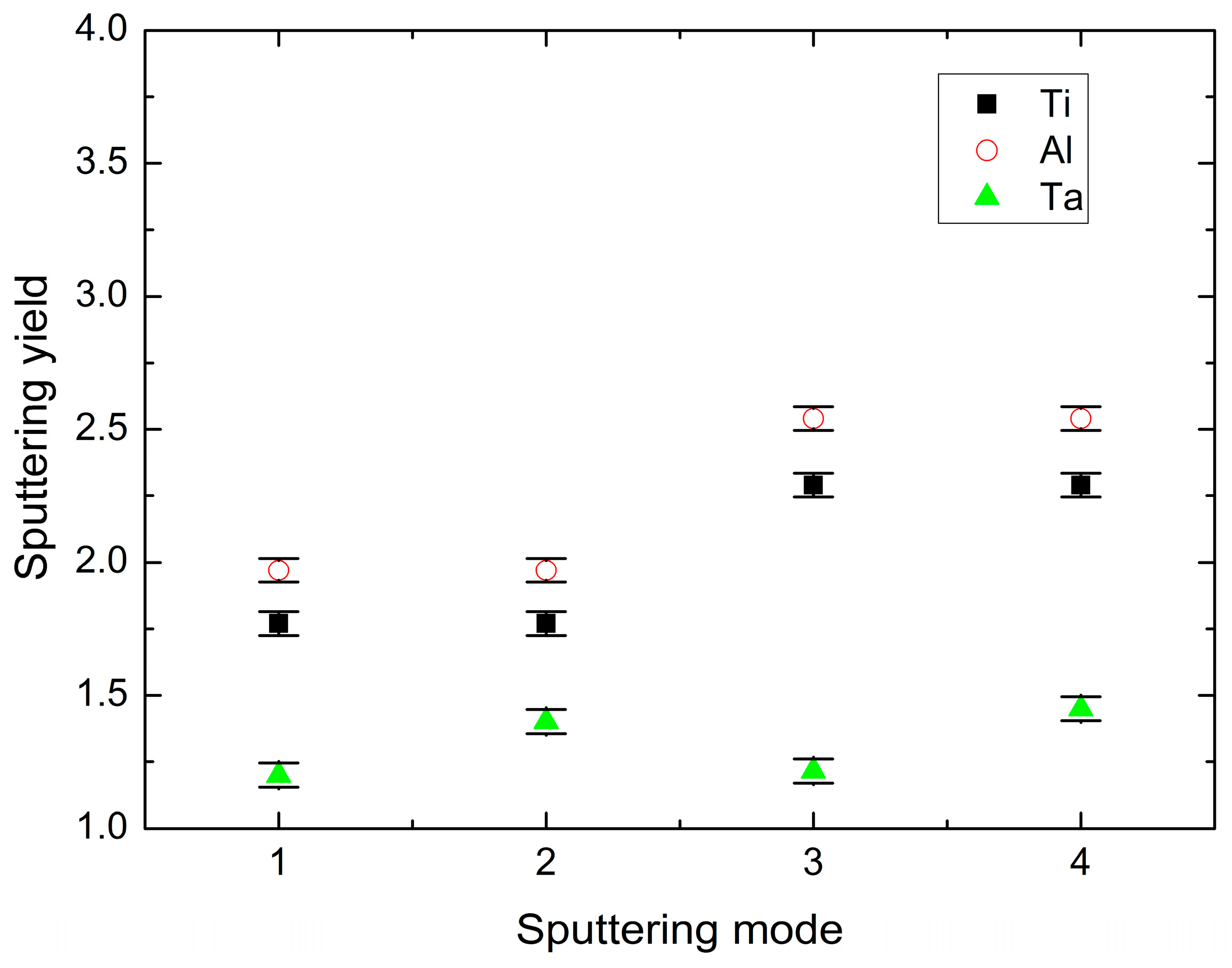
3.1. Chemical Composition
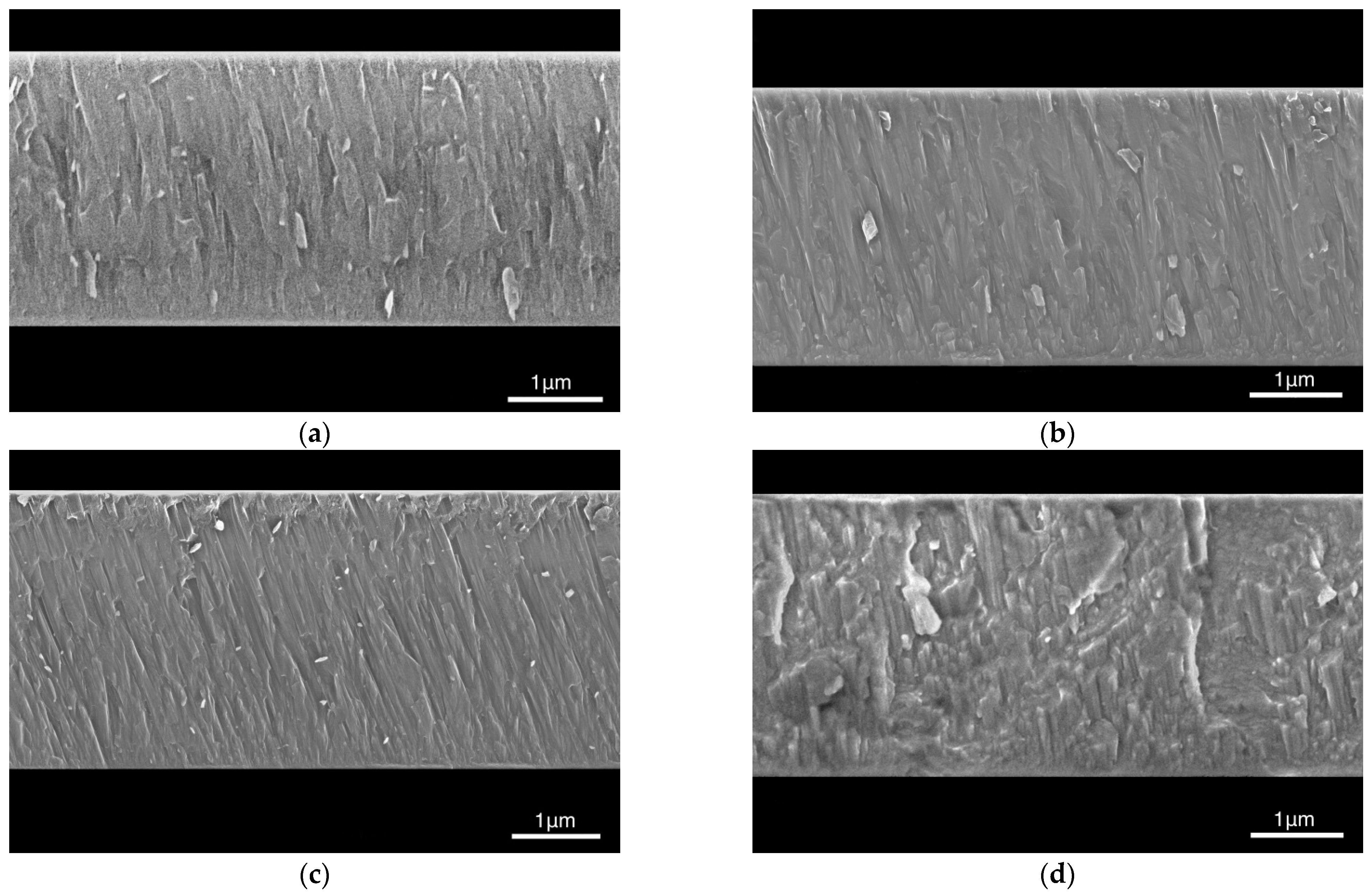
The chemical compositions of the Ti-Al-Ta-N coatings deposited in different sputtering modes determined by EDS are listed in Table 1. It can be seen that, despite similar average cathode power densities, the composition of the coatings varies significantly. This effect is mainly caused by two origins. The first is concerned with different sputtering yields of the target materials in the different sputtering modes. The estimation of the sputtering yield of the chemical elements constituting the targets was performed using the following equation [67]:
S = 3 · α · M 1 · M 2 · E π 2 · M 1 + M 2 2 · U s ,
where α is the dimensionless coefficient dependent on the M2/M1 ratio, M1 is the molar mass of the incident ion, M2 is the molar mass of the sputtered atom, E is the energy of the incident ion, and Us is the bonding energy of the target materials. It has been found that the sputtering yield considerably increases in the DSMS mode because of the higher peak cathode power and, consequently, the higher energy of bombarding ions (see Figure 1). For example, in mode 2, where the Ti-Al target was sputtered in the DC mode, and the Ta target in the pulsed mode, the sputtering yield of Ta was only ~25% lower than that of Ti. In contrast, in mode 3, where the sputtering of the Ti-Al target was performed in the MFMS mode and the Ta target was sputtered by applying direct current, the sputtering yield of Ta was ~1.9 times lower than that of Ti. Therefore, the Ta concentration in the metal constituent of the coatings decreased from 19.0 at.% in mode 2 to 11.6 at.% in mode 3. The second origin is concerned with reactions of the atoms of target materials with nitrogen ions present in the flux of bombarding species, which lead to “poisoning” of the targets, i.e., the formation of dielectric nitride layers on their surface. These layers substantially decrease the sputtering yield since they favor the accumulation of positive charge on the target surface, which shields it from the bombarding ions. In addition, the sputtering yield of nitrides is considerably lower than that of pure metals.
Standard Gibbs free energy of formation of TiN (−308.3 kJ/mol) is more negative than those of AlN (−287.0 kJ/mol) and TaN (−187 kJ/mol) [68,69]. Therefore, it can be supposed that the Ti-Al target was most strongly “poisoned” in the Ti-enriched areas during the sputtering process. This led to a rapid drop in the number of Ti atoms in the flux of the sputtered species compared with the Al and Ta atoms, which were still predominantly sputtered in the metallic mode. This effect was earlier revealed in magnetron-sputtered Ti-Al-N coatings, where pronounced changes in the Al/Ti ratio were observed under a varying partial pressure of nitrogen [70]. Evidently, the “poisoning” was substantially more pronounced in the DCMS mode since, in this case, the charging of the dielectric nitride layers on the target surface occurred continuously. In the case of the pulsed bipolar magnetron sputtering, the nitride layers discharged during the period when a positive potential was applied to the target due to an electron current from the deionizing plasma. This resulted in a weaker shielding of the Ti-enriched areas of the Ti-Al target and, consequently, in an increase in the fraction of Ti atoms in the sputtered flux. Therefore, the Ti content in the coatings increased from 39.3% in mode 1 to 43.7% in mode 3 and 46.5% in mode 4.
The Al and Ta contents in the Ti-Al-Ta-N coatings change in an even more complex manner than the Ti content. In the coatings sputtered in mode 2, the Al content dropped by 19% compared with the coatings obtained in mode 1, whereas the Ta content increased by 25%. The increase in the Ta content is concerned with the higher sputtering yield of Ta in the MFMS mode, which was used for the sputtering of the Ta target in mode 2. The decrease in the Al content is supposed to be due to the intensive scattering of light Al atoms owing to their collisions with heavy Ta atoms. Considering that the co-sputtering was performed with crossed fluxes of the particles sputtered from the Ti-Al and Ta targets, the increase in the flux of Ta atoms resulted in an increase in the amount of the scattered Al atoms, and, therefore, in a decrease in their fraction in the flux of species forming the coating. In the coatings deposited in mode 3 the Al content increased again, while the Ta content was reduced due to a decrease in the flux of the Ta atoms, which were sputtered in the DCMS mode. Nevertheless, the Al content in mode 3 was lower than in mode 1 since the pulsed sputtering of the Ti-Al target provided a higher number of sputtered Ti atoms, as discussed above. Finally, in mode 4, where both targets were sputtered in the MFMS mode, the Al content drops to a minimum value because of a simultaneous increase in the amount of sputtered Ti and Ta atoms.

3.2. Structure

Despite the different chemical compositions of the Ti-Al-Ta-N coatings obtained in the different sputtering modes, the XRD studies did not reveal significant differences in their phase compositions. As shown in Figure 2, which displays the XRD patterns of the samples, all of the coatings are comprised of the Ti-Al-Ta-N solid solution with a single-phase FCC (B1) structure, where crystallites are preferentially grown along the [111] direction. The changes in the chemical composition of the coatings result in shifts of the XRD peaks, which indicate variations of the lattice constant a of the solid solution. The values of the lattice constant extracted from the XRD patterns are listed in Table 1, which makes it evident that a increases with increasing the Ta/Al content ratio. Since the lattice constant of cubic AlN (0.412 nm) is smaller than that of TiN (0.424), and the lattice constant of cubic TaN (0.434), on the contrary, is larger, an increase in the Al content in the coatings leads to decreasing a, whereas an increase in the Ta content results in its increase. Therefore, the increasing Ta/Al content increases a, and consequently, to the shift of the Ti-Al-Ta-N peaks toward lower diffraction angles. In addition, the coatings sputtered in modes 2–4 are characterized by a considerable broadening of the XRD peaks, which can be attributed to large lattice distortions and the small size of the coherently diffracting domains d. The values of d were estimated using the Debye–Scherrer equation [71]
d = K λ β   cos   θ
where K is the Scherer’s constant, λ is the X-ray wavelength, and β is the full width at half the maximum of the diffraction peak. They are listed in Table 1. It should be noted that the crystallite size determined through XRD analysis is often smaller than the grain or subgrain size obtained from direct observations of the material microstructure using scanning electron microscopy or transmission electron microscopy. In addition to the differences in orientation between grains or subgrains, this has also been attributed to the presence of dipolar dislocation walls, which break down the coherency of X-ray scattering [72]. It can be seen that the coatings obtained in modes 2–4 are characterized by close sizes of the coherently diffracting domains, which are less than half the size of those in the coating sputtered in mode 1. Thus, the use of MFMS mode provides the refinement of the crystal structure of the Ti-Al-Ta-N coatings.
Figure 3 shows typical SEM micrographs of fracture cross-sections of the coatings deposited in different sputtering modes. The coatings obtained in modes 1–3 are seen to have a columnar microstructure. In contrast, the coating prepared in mode 4, which utilized the pulsed sputtering of both targets, is characterized by a denser mixed microstructure comprised of fragmented columnar grains and equiaxed grains.

3.3. Mechanical Properties

It has been found that all of the Ti-Al-Ta-N coatings studied are characterized by compressive residual stresses; their values are listed in Table 1. It should be noted that the coatings deposited in the modes where at least one of the targets was sputtered in the MFMS mode demonstrate lower stresses compared with the DCMS coating (mode 1). Moreover, the lowest residual stress was found in the coating deposited in mode 4 when both targets were sputtered in the MFMS mode.
The hardness and reduced Young’s modulus of the coatings determined through the instrumented nanoindentation are shown in Figure 4. The presented results indicate that the middle-frequency magnetron sputtering provides an increase in H and E*. The hardness of the coatings sputtered in modes 2–4 is 1–2 GPa higher compared with that deposited in mode 1, with the coating obtained in pure MFMS mode having the highest hardness. The observed increase in the hardness can be attributed to the reduced average crystallite size of the coatings deposited in modes 2–4, as it was evidenced by the XRD investigations. It is known that the decrease in the crystallite size down to 10–20 nm enhances the hardness of polycrystalline materials due to hindering the dislocation motions because of the increasing boundary areas and the formation of dislocation pile-ups (Hall–Petch effect) [73,74]. The Young’s modulus of the coatings deposited in modes 2–4 increases by 10% compared with that sputtered in mode 1, which can be attributed to the densification of their structure.

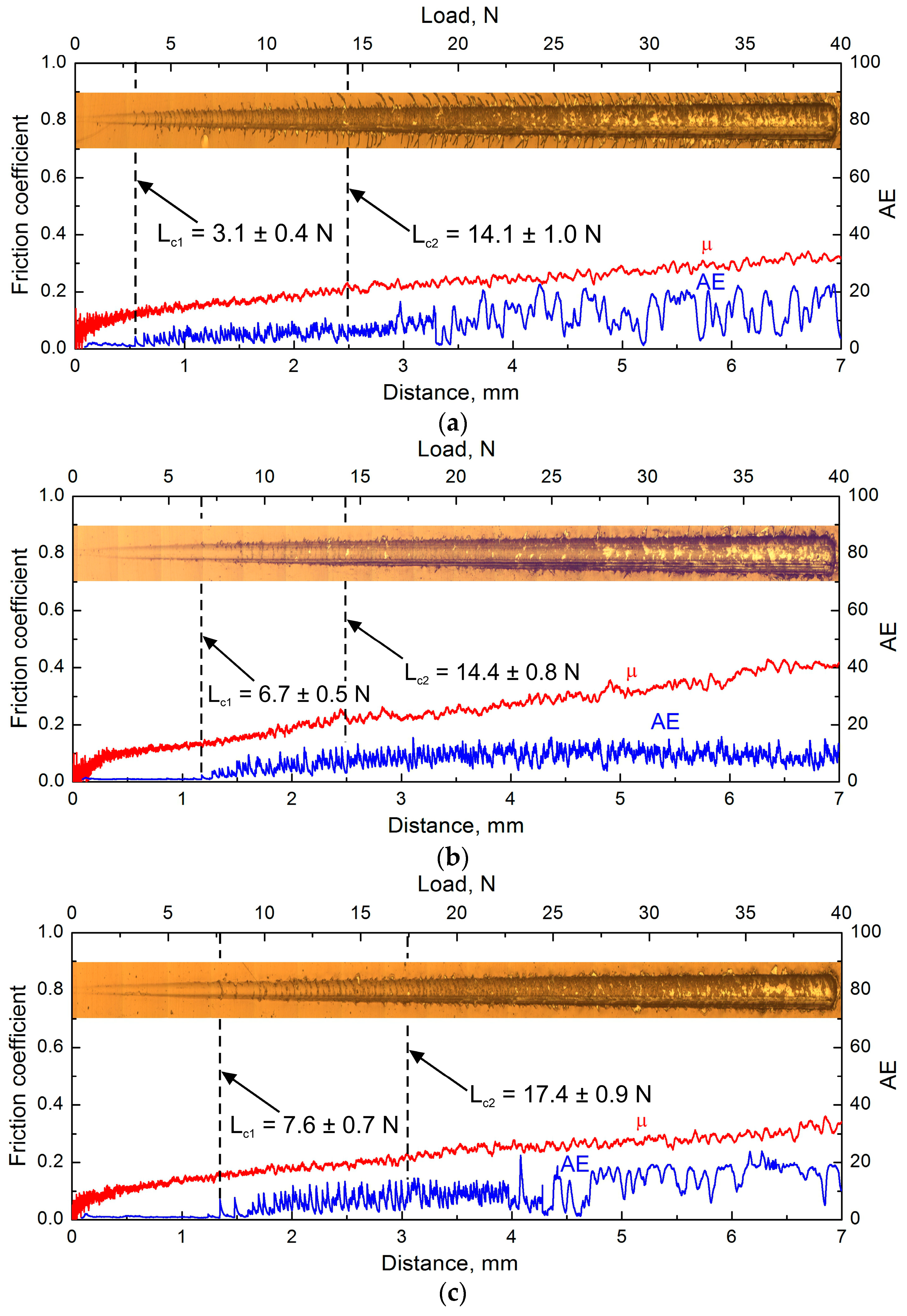
3.4. Scratch Behavior
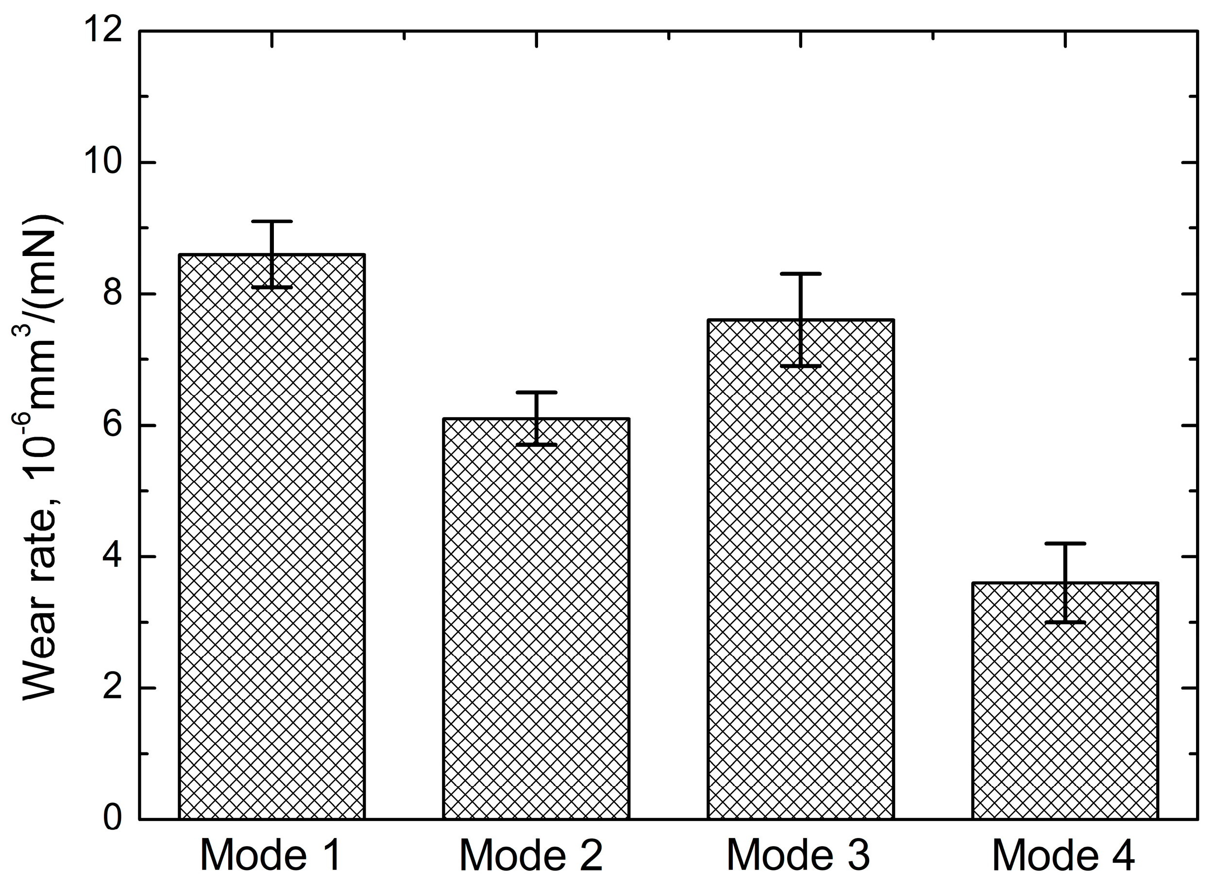
Scratch testing of the coatings has revealed that the moving stylus induces plastic ploughing of the material of the steel substrate from the bottom of the scratch groove toward its flanks. This results in the formation of pile-ups along the scratch flanks, which is accompanied by coherent bending of the coatings. As shown in Figure 5, the coating failure starts from the formation of conformal cracks inside the scratch grooves. They are semicircular forward cracks caused by compressive stresses arising ahead of the moving stylus, resulting in the formation of the pile-up in this area. Due to the rigid bonding between the coating and the substrate, the former bends in the pile-up area, leading to rising tensile stresses in its surface layer, resulting in coating cracking at the periphery of the contact area. Tensile backward cracks also form at higher loads inside the scratch tracks, which are induced by the total effect of the friction force and the bending of the coatings around the contact area.
The formation of the first cracks in the scratch grooves during scratching was registered by the appearance of sudden AE peaks, which were caused by abrupt local relaxation of stresses and propagation of the corresponding elastic waves. The critical load Lc1 corresponding to the first registered crack event in the coatings corresponds to the beginning of their cohesive fracture, and therefore it can be used to characterize their toughness. The measured Lc1 values indicated in Figure 5 make it clear that the DCMS Ti-Al-Ta-N coating has the lowest toughness. In contrast, the MFMS coating is characterized by the highest Lc1 value. The increase in the applied load above the Lc1 value eventually leads to the local delamination and spallation of the coatings fragments. These events determine the critical load Lc2, which characterizes coating adhesion. It can be seen from Figure 5 that the DCMS coating has the poorest adhesion, while the MFMS coating is characterized by the strongest adhesion. Thus, the scratch testing reveals that the MFMS technique allows enhancing both the toughness and adhesion of the Ti-Al-Ta-N coatings compared with conventional DCMS.

3.5. Wear

Figure 6 exhibits the friction coefficient of the Ti-Al-Ta-N coatings obtained in different sputtering modes as a function of the sliding distance under conditions of dry friction. It is seen that the friction coefficient of all coatings increases rapidly at the running-in stage, reaching stable values in the range from 0.49 to 0.57 during the steady-state wear stage. The DCMS coating has the highest friction coefficient, whereas the MFMS coating is characterized by its lowest value.
Abrasive wear was found to be the main wear mechanism of the Ti-Al-Ta-N coatings, which is typical for TiN-based coatings [75,76]. The wear debris formed due to the chipping of the coatings was transferred along the wear tracks and partially adhered to the wear surface. The adhered layers were partially oxidized during the tests resulting in the formation of tribofilms consisting of Ti, Al and Ta oxides at some areas of the wear tracks. Such oxide tribofilms can act as a solid lubricant, reducing the friction coefficient of the coatings and thereby increasing their wear resistance [77]. However, the tribofilms did not completely cover the wear tracks and could be quite easily removed by abrasion during the following testing. Therefore, it can be supposed that the oxide tribofilms do not significantly contribute to the wear resistance of the coatings studied.
Figure 7 shows the wear rate of the Ti-Al-Ta-N coatings sputtered in different modes. It is seen that the coatings deposited in MFMS and hybrid modes (modes 2–4) are characterized by improved wear performance compared with the DCMS coating. The MFMS coating has the lowest wear rate, which is 2.4 times lower than that of the DCMS coating. Considering the above-described results, the improved wear performance of the MFMS Ti-Al-Ta-N coating can be primarily attributed to the modification of its microstructure. Hindering the formation of columnar grains with low-density boundaries and reducing the crystallite size resulted in the densification of the MFMS coating, which provided its increased hardness in combination with improved toughness. In addition, the absence of the through-thickness boundaries between columns significantly suppressed the propagation of cracks toward the substrate, enhancing the resistance of the coating to chipping and delamination. All of these factors contribute to its increased resistance to scratching and abrasion.

4. Conclusions

A comparative study of the chemical composition and the structure, mechanical, and tribological properties of the Ti-Al-Ta-N coatings deposited by DC magnetron sputtering, middle-frequency magnetron sputtering as well as using hybrid techniques, where one target was sputtered in the DCMS mode, and another in the MFMS mode, was performed. It was shown that the middle-frequency co-sputtering of both Ti-Al and Ta targets hindered the formation of columnar grains extending throughout the whole coating thickness, which resulted in its denser mixed microstructure, consisting of fragmented columnar grains and equiaxed grains. Hindering the growth of columnar grains and decreasing the crystallite size of the MFMS coating resulted in a simultaneous increase in its hardness and toughness as well as the suppression of the propagation of through-thickness cracks. All of these factors provided a synergetic effect in improving wear resistance. As a result, the wear resistance of the MFMS coating was more than twice as much as that of the DCMS coating. Thus, the study has shown that middle-frequency magnetron sputtering is a promising technique for obtaining Ti-Al-Ta-N coatings with improved properties.

Author Contributions

Conceptualization, A.R.S.; methodology, A.R.S.; investigation, E.D.K., Y.A.G., and A.R.S.; writing—original draft preparation, A.R.S.; writing—review and editing, A.R.S.; visualization, Y.A.G. and E.D.K.; supervision, A.R.S. All authors have read and agreed to the published version of the manuscript.

Funding

The work was funded by the Russian Government according to the research assignment for ISPMS SB RAS, project FWRW-2021-0010.

Institutional Review Board Statement

Not applicable.

Informed Consent Statement

Not applicable.

Data Availability Statement

The data presented in this study are available on request from the corresponding author.

Acknowledgments

SEM investigations and scratch-testing have been carried out using the equipment of Share Use Centre “Nanotech” of the ISPMS SB RAS. XRD studies have been performed using the equipment of the Center for sharing use “Nanomaterials and nanotechnologies” of Tomsk Polytechnic University supported by the RF Ministry of Education and Science, project #075-15-2021-710.

Conflicts of Interest

The authors declare no conflict of interest.

References

  1. Al-Asadi, M.M.; Al-Tameemi, H.A. A Review of Tribological Properties and Deposition Methods for Selected Hard Protective Coatings. Tribol. Int. 2022, 176, 107919. [Google Scholar] [CrossRef]
  2. Arun, K.L.; Udhayakumar, M.; Radhika, N. A Comprehensive Review on Various Ceramic Nanomaterial Coatings Over Metallic Substrates: Applications, Challenges and Future Trends. J. Bio. Tribocorros. 2022, 9, 11. [Google Scholar] [CrossRef]
  3. Cao, X.; He, W.; He, G.; Liao, B.; Zhang, H.; Chen, J.; Lv, C. Sand Erosion Resistance Improvement and Damage Mechanism of TiAlN Coating via the Bias-Graded Voltage in FCVA Deposition. Surf. Coat. Technol. 2019, 378, 125009. [Google Scholar] [CrossRef]
  4. Tillmann, W.; Grisales, D.; Stangier, D.; Butzke, T. Tribomechanical Behaviour of TiAlN and CrAlN Coatings Deposited onto AISI H11 with Different Pre-Treatments. Coatings 2019, 9, 519. [Google Scholar] [CrossRef] [Green Version]
  5. Zhang, M.; Cheng, Y.; Xin, L.; Su, J.; Li, Y.; Zhu, S.; Wang, F. Cyclic Oxidation Behaviour of Ti/TiAlN Composite Multilayer Coatings Deposited on Titanium Alloy. Corros. Sci. 2020, 166, 108476. [Google Scholar] [CrossRef]
  6. PalDey, S.; Deevi, S.C. Single Layer and Multilayer Wear Resistant Coatings of (Ti,Al)N: A Review. Mater. Sci. Eng. A 2003, 342, 58–79. [Google Scholar] [CrossRef]
  7. Sousa, V.F.C.; da Silva, F.J.G.; Pinto, G.F.; Baptista, A.; Alexandre, R. Characteristics and Wear Mechanisms of TiAlN-Based Coatings for Machining Applications: A Comprehensive Review. Metals 2021, 11, 260. [Google Scholar] [CrossRef]
  8. Jing, L.; Chen, M.; An, Q. Study on Performance of PVD AlTiN Coatings and AlTiN-Based Composite Coatings in Dry End Milling of Hardened Steel SKD11. Metals 2021, 11, 2019. [Google Scholar] [CrossRef]
  9. Shugurov, A.R.; Panin, A.V.; Dmitriev, A.I.; Nikonov, A.Y. Multiscale Fracture of Ti-Al-N Coatings under Uniaxial Tension. Phys. Mesomech. 2021, 24, 185–195. [Google Scholar] [CrossRef]
  10. Sangiovanni, D.G.; Chirita, V.; Hultman, L. Toughness Enhancement in TiAlN-Based Quarternary Alloys. Thin Solid Films 2012, 520, 4080–4088. [Google Scholar] [CrossRef] [Green Version]
  11. Mikula, M.; Plašienka, D.; Sangiovanni, D.G.; Sahul, M.; Roch, T.; Truchlý, M.; Gregor, M.; Čaplovič, L.; Plecenik, A.; Kúš, P. Toughness Enhancement in Highly NbN-Alloyed Ti-Al-N Hard Coatings. Acta Mater. 2016, 121, 59–67. [Google Scholar] [CrossRef]
  12. Chen, Y.H.; Roa, J.J.; Yu, C.H.; Johansson-Jõesaar, M.P.; Andersson, J.M.; Anglada, M.J.; Odén, M.; Rogström, L. Enhanced Thermal Stability and Fracture Toughness of TiAlN Coatings by Cr, Nb and V-Alloying. Surf. Coat. Technol. 2018, 342, 85–93. [Google Scholar] [CrossRef]
  13. Eremeev, S.V.; Shugurov, A.R. Chemical Bonding Analysis in Ti1-x-yAlxTayN Solid Solutions. Surf. Coat. Technol. 2020, 395, 125803. [Google Scholar] [CrossRef]
  14. Shuai, J.; Zuo, X.; Wang, Z.; Guo, P.; Xu, B.; Zhou, J.; Wang, A.; Ke, P. Comparative Study on Crack Resistance of TiAlN Monolithic and Ti/TiAlN Multilayer Coatings. Ceram. Int. 2020, 46, 6672–6681. [Google Scholar] [CrossRef]
  15. Tillmann, W.; Grisales, D.; Stangier, D.; Thomann, C.A.; Debus, J.; Nienhaus, A.; Apel, D. Residual Stresses and Tribomechanical Behaviour of TiAlN and TiAlCN Monolayer and Multilayer Coatings by DCMS and HiPIMS. Surf. Coat. Technol. 2021, 406, 126664. [Google Scholar] [CrossRef]
  16. Kameda, J.; Bloomer, I.E.; Sugita, Y.; Ito, A.; Sakurai, S. High Temperature Environmental Attack and Mechanical Degradation of Coatings in Gas Turbine Blades. Mater. Sci. Eng. A 1997, 229, 42–54. [Google Scholar] [CrossRef]
  17. Liew, W.Y.H.; Lim, H.P.; Melvin, G.J.H.; Dayou, J.; Jiang, Z.-T. Thermal Stability, Mechanical Properties, and Tribological Performance of TiAlXN Coatings: Understanding the Effects of Alloying Additions. J. Mater. Res. Technol. 2022, 17, 961–1012. [Google Scholar] [CrossRef]
  18. Rachbauer, R.; Holec, D.; Mayrhofer, P.H. Increased Thermal Stability of Ti–Al–N Thin Films by Ta Alloying. Surf. Coat. Technol. 2012, 211, 98–103. [Google Scholar] [CrossRef]
  19. Hollerweger, R.; Riedl, H.; Paulitsch, J.; Arndt, M.; Rachbauer, R.; Polcik, P.; Primig, S.; Mayrhofer, P.H. Origin of High Temperature Oxidation Resistance of Ti–Al–Ta–N Coatings. Surf. Coat. Technol. 2014, 257, 78–86. [Google Scholar] [CrossRef] [Green Version]
  20. Yang, Y.; Xu, Y.X.; Chen, L.; Mayrhofer, P.H. Improved Ti-Al-N Coatings through Ta Alloying and Multilayer Architecture. Surf. Coat. Technol. 2017, 328, 428–435. [Google Scholar] [CrossRef]
  21. Seidl, W.M.; Bartosik, M.; Kolozsvári, S.; Bolvardi, H.; Mayrhofer, P.H. Improved Mechanical Properties, Thermal Stabilities, and Oxidation Resistance of Arc Evaporated Ti-Al-N Coatings through Alloying with Ta. Surf. Coat. Technol. 2018, 344, 244–249. [Google Scholar] [CrossRef]
  22. Shugurov, A.R.; Kuzminov, E.D.; Kasterov, A.M.; Panin, A.V.; Dmitriev, A.I. Tuning of Mechanical Properties of Ti1-xAlxN Coatings through Ta Alloying. Surf. Coat. Technol. 2020, 382, 125219. [Google Scholar] [CrossRef]
  23. Shugurov, A.; Panin, A.; Kasterov, A. Effect of Ta Alloying on Isothermal Oxidation Behavior of DC Magnetron Sputtered Ti1-xAlxN Coatings on Titanium Substrate. Surf. Coat. Technol. 2021, 421, 127488. [Google Scholar] [CrossRef]
  24. Hemmati, A.; Abdoos, M.; Veldhuis, S.C. Developing Ti-Al-Ta-N Based Coatings: Thermal Stability, Oxidation Resistance, Machining Performance and Adaptive Behavior under Extreme Tribological Conditions. Mater. Today Commun. 2022, 31, 103373. [Google Scholar] [CrossRef]
  25. Pfeiler, M.; Fontalvo, G.A.; Wagner, J.; Kutschej, K.; Penoy, M.; Michotte, C.; Mitterer, C.; Kathrein, M. Arc Evaporation of Ti-Al-Ta-N Coatings: The Effect of Bias Voltage and Ta on High-Temperature Tribological Properties. Tribol. Lett. 2008, 30, 91–97. [Google Scholar] [CrossRef]
  26. Grossmann, B.; Tkadletz, M.; Schalk, N.; Czettl, C.; Pohler, M.; Mitterer, C. High-Temperature Tribology and Oxidation of Ti1-x-yAlxTayN Hard Coatings. Surf. Coat. Technol. 2018, 342, 190–197. [Google Scholar] [CrossRef]
  27. Shugurov, A.R.; Kuzminov, E.D.; Kasterov, A.M.; Akulinkin, A.A. The Effect of Ta Alloying on Mechanical and Tribological Properties of Ti-Al-N Coatings. AIP Conf. Proc. 2020, 2310, 020314. [Google Scholar] [CrossRef]
  28. Meyer, Y.A.; Menezes, I.; Bonatti, R.S.; Bortolozo, A.D.; Osório, W.R. EIS Investigation of the Corrosion Behavior of Steel Bars Embedded into Modified Concretes with Eggshell Contents. Metals 2022, 12, 417. [Google Scholar] [CrossRef]
  29. Keerthiga, G.; Vijayshankar, D.; Prasad, M.; Peron, M.; Albinmousa, J.; Singh Raman, R.K. Electrochemical Corrosion Resistance of Mg Alloy ZK60 in Different Planes with Respect to Extrusion Direction. Metals 2022, 12, 782. [Google Scholar] [CrossRef]
  30. Satizabal, L.M.; Costa, D.; Moraes, P.B.; Bortolozo, A.D.; Osório, W.R. Microstructural Array and Solute Content Affecting Electrochemical Behavior of SnAg and SnBi Alloys Compared with a Traditional SnPb Alloy. Mater. Chem. Phys. 2019, 223, 410–425. [Google Scholar] [CrossRef]
  31. Donelan, P. Modelling Microstructural and Mechanical Properties of Ferritic Ductile Cast Iron. Mater. Sci. Technol. 2000, 16, 261–269. [Google Scholar] [CrossRef]
  32. Petch, N.J. The Cleavage Strength of Polycrystals. J. Iron Steel Inst. 1953, 174, 25–28. [Google Scholar]
  33. Seidl, W.M.; Bartosik, M.; Kolozsvári, S.; Bolvardi, H.; Mayrhofer, P.H. Influence of Ta on the Fracture Toughness of Arc Evaporated Ti-Al-N. Vacuum 2018, 150, 24–28. [Google Scholar] [CrossRef]
  34. Koller, C.M.; Glatz, S.A.; Riedl, H.; Kolozsvári, S.; Polcik, P.; Bolvardi, H.; Mayrhofer, P.H. Structure and Mechanical Properties of Architecturally Designed Ti-Al-N and Ti-Al-Ta-N-Based Multilayers. Surf. Coat. Technol. 2020, 385, 125355. [Google Scholar] [CrossRef]
  35. Khetan, V.; Valle, N.; Duday, D.; Michotte, C.; Delplancke-Ogletree, M.-P.; Choquet, P. Influence of Temperature on Oxidation Mechanisms of Fiber-Textured AlTiTaN Coatings. ACS Appl. Mater. Interfaces 2014, 6, 4115–4125. [Google Scholar] [CrossRef]
  36. Sui, X.; Li, G.; Jiang, C.; Yu, H.; Wang, K.; Wang, Q. Effect of Ta Content on Microstructure, Hardness and Oxidation Resistance of TiAlTaN Coatings. Int. J. Refract. Metals Hard Mater. 2016, 58, 152–156. [Google Scholar] [CrossRef]
  37. Contreras Romero, E.; Cortínez Osorio, J.; Talamantes Soto, R.; Hurtado Macías, A.; Gómez Botero, M. Microstructure, Mechanical and Tribological Performance of Nanostructured TiAlTaN-(TiAlN/TaN)n Coatings: Understanding the Effect of Quaternary/Multilayer Volume Fraction. Surf. Coat. Technol. 2019, 377, 124875. [Google Scholar] [CrossRef]
  38. Smidt, F.A. Use of Ion Beam Assisted Deposition to Modify the Microstructure and Properties of Thin Films. Int. Mater. Rev. 1990, 35, 61–128. [Google Scholar] [CrossRef]
  39. Petrov, I.; Barna, P.B.; Hultman, L.; Greene, J.E. Microstructural Evolution during Film Growth. J. Vac. Sci. Technol. A 2003, 21, 117–128. [Google Scholar] [CrossRef]
  40. Kelly, P.J.; Beevers, C.F.; Henderson, P.S.; Arnell, R.D.; Bradley, J.W.; Bäcker, H. A Comparison of the Properties of Titanium-Based Films Produced by Pulsed and Continuous DC Magnetron Sputtering. Surf. Coat. Technol. 2003, 174–175, 795–800. [Google Scholar] [CrossRef]
  41. Lin, J.; Moore, J.J.; Sproul, W.D.; Mishra, B.; Wu, Z.; Wang, J. The Structure and Properties of Chromium Nitride Coatings Deposited Using DC, Pulsed DC and Modulated Pulse Power Magnetron Sputtering. Surf. Coat. Technol. 2010, 204, 2230–2239. [Google Scholar] [CrossRef]
  42. Fager, H.; Howe, B.M.; Greczynski, G.; Jensen, J.; Mei, A.B.; Lu, J.; Hultman, L.; Greene, J.E.; Petrov, I. Novel Hard, Tough HfAlSiN Multilayers, Defined by Alternating Si Bond Structure, Deposited Using Modulated High-Flux, Low-Energy Ion Irradiation of the Growing Film. J. Vac. Sci. Technol. A 2015, 33, 05E103. [Google Scholar] [CrossRef]
  43. Zhang, P.; Cai, Z.; Xiong, W. Influence of Si Content and Growth Condition on the Microstructure and Mechanical Properties of Ti–Si–N Nanocomposite Films. Surf. Coat. Technol. 2007, 201, 6819–6823. [Google Scholar] [CrossRef]
  44. Adibi, F.; Petrov, I.; Greene, J.E.; Hultman, L.; Sundgren, J.-E. Effects of High-flux Low-energy (20–100 eV) Ion Irradiation during Deposition on the Microstructure and Preferred Orientation of Ti0.5Al0.5N Alloys Grown by Ultra-high-vacuum Reactive Magnetron Sputtering. J. Appl. Phys. 1993, 73, 8580–8589. [Google Scholar] [CrossRef]
  45. Windischmann, H. Intrinsic Stress in Sputter-Deposited Thin Films. Crit. Rev. Solid State Mater. Sci. 1992, 17, 547–596. [Google Scholar] [CrossRef]
  46. Greczynski, G.; Lu, J.; Jensen, J.; Petrov, I.; Greene, J.E.; Bolz, S.; Kölker, W.; Schiffers, C.; Lemmer, O.; Hultman, L. Metal versus Rare-Gas Ion Irradiation during Ti1-xAlxN Film Growth by Hybrid High Power Pulsed Magnetron/DC Magnetron Co-Sputtering Using Synchronized Pulsed Substrate Bias. J. Vac. Sci. Technol. A 2012, 30, 061504. [Google Scholar] [CrossRef] [Green Version]
  47. Hultman, L.; Håkansson, G.; Wahlström, U.; Sundgren, J.E.; Petrov, I.; Adibi, F.; Greene, J.E. Transmission Electron Microscopy Studies of Microstructural Evolution, Defect Structure, and Phase Transitions in Polycrystalline and Epitaxial Ti1-xAlxN and TiN Films Grown by Reactive Magnetron Sputter Deposition. Thin Solid Films 1991, 205, 153–164. [Google Scholar] [CrossRef]
  48. Petrov, I.; Hultman, L.; Helmersson, U.; Sundgren, J.E.; Greene, J.E. Microstructure Modification of TiN by Ion Bombardment during Reactive Sputter Deposition. Thin Solid Films 1989, 169, 299–314. [Google Scholar] [CrossRef]
  49. Greene, J.E. Review Article: Tracing the Recorded History of Thin-Film Sputter Deposition: From the 1800s to 2017. J. Vac. Sci. Technol. A 2017, 35, 05C204. [Google Scholar] [CrossRef] [Green Version]
  50. Fager, H.; Tengstrand, O.; Lu, J.; Bolz, S.; Mesic, B.; Kölker, W.; Schiffers, C.; Lemmer, O.; Greene, J.E.; Hultman, L.; et al. Low-Temperature Growth of Dense and Hard Ti0.41Al0.51Ta0.08N Films via Hybrid HIPIMS/DC Magnetron Co-Sputtering with Synchronized Metal-Ion Irradiation. J. Appl. Phys. 2017, 121, 171902. [Google Scholar] [CrossRef] [Green Version]
  51. Greczynski, G.; Mráz, S.; Schneider, J.M.; Hultman, L. Metal-Ion Subplantation: A Game Changer for Controlling Nanostructure and Phase Formation during Film Growth by Physical Vapor Deposition. J. Appl. Phys. 2020, 127, 180901. [Google Scholar] [CrossRef]
  52. Barshilia, H.C.; Prakash, M.S.; Sridhara Rao, D.V.; Rajam, K.S. Superhard Nanocomposite Coatings of TiN/a-C Prepared by Reactive DC Magnetron Sputtering. Surf. Coat. Technol. 2005, 195, 147–153. [Google Scholar] [CrossRef]
  53. AL-Rjoub, A.; Yaqub, T.B.; Cavaleiro, A.; Fernandes, F. The Influence of V Addition on the Structure, Mechanical Properties, and Oxidation Behaviour of TiAlSiN Coatings Deposited by DC Magnetron Sputtering. J. Mater. Res. Technol. 2022, 20, 2444–2453. [Google Scholar] [CrossRef]
  54. Shugurov, A.R.; Kuzminov, E.D. Mechanical and Tribological Properties of Ti-Al-Ta-N/TiAl and Ti-Al-Ta-N/Ta Multilayer Coatings Deposited by DC Magnetron Sputtering. Surf. Coat. Technol. 2022, 441, 128582. [Google Scholar] [CrossRef]
  55. Konstantinidis, S.; Ricard, A.; Ganciu, M.; Dauchot, J.P.; Ranea, C.; Hecq, M. Measurement of Ionic and Neutral Densities in Amplified Magnetron Discharges by Pulsed Absorption Spectroscopy. J. Appl. Phys. 2004, 95, 2900–2905. [Google Scholar] [CrossRef]
  56. Petrov, I.; Myers, A.; Greene, J.E.; Abelson, J.R. Mass and Energy Resolved Detection of Ions and Neutral Sputtered Species Incident at the Substrate during Reactive Magnetron Sputtering of Ti in Mixed Ar+N2 Mixtures. J. Vac. Sci. Technol. A 1994, 12, 2846–2854. [Google Scholar] [CrossRef]
  57. Kouznetsov, V.; MacÁk, K.; Schneider, J.M.; Helmersson, U.; Petrov, I. A Novel Pulsed Magnetron Sputter Technique Utilizing Very High Target Power Densities. Surf. Coat. Technol. 1999, 122, 290–293. [Google Scholar] [CrossRef]
  58. Bohlmark, J.; Alami, J.; Christou, C.; Ehiasarian, A.P.; Helmersson, U. Ionization of Sputtered Metals in High Power Pulsed Magnetron Sputtering. J. Vac. Sci. Technol. A 2004, 23, 18–22. [Google Scholar] [CrossRef]
  59. Kelly, P.J.; vom Braucke, T.; Liu, Z.; Arnell, R.D.; Doyle, E.D. Pulsed DC Titanium Nitride Coatings for Improved Tribological Performance and Tool Life. Surf. Coat. Technol. 2007, 202, 774–780. [Google Scholar] [CrossRef]
  60. Tillmann, W.; Lopes Dias, N.F.; Stangier, D.; Tolan, M.; Paulus, M. Structure and Mechanical Properties of Hafnium Nitride Films Deposited by Direct Current, Mid-Frequency, and High-Power Impulse Magnetron Sputtering. Thin Solid Films 2019, 669, 65–71. [Google Scholar] [CrossRef]
  61. Gudmundsson, J.T.; Alami, J.; Helmersson, U. Spatial and Temporal Behavior of the Plasma Parameters in a Pulsed Magnetron Discharge. Surf. Coat. Technol. 2002, 161, 249–256. [Google Scholar] [CrossRef]
  62. Lin, J.; Wu, Z.L.; Zhang, X.H.; Mishra, B.; Moore, J.J.; Sproul, W.D. A Comparative Study of CrNx Coatings Synthesized by DC and Pulsed DC Magnetron Sputtering. Thin Solid Films 2009, 517, 1887–1894. [Google Scholar] [CrossRef]
  63. Khamseh, S.; Nose, M.; Kawabata, T.; Nagae, T.; Matsuda, K.; Ikeno, S. A Comparative Study of CrAlN Films Synthesized by DC and Pulsed DC Reactive Magnetron Facing Target Sputtering System with Different Pulse Frequencies. J. Alloys. Compd. 2010, 508, 191–195. [Google Scholar] [CrossRef]
  64. Bagcivan, N.; Bobzin, K.; Ludwig, A.; Grochla, D.; Brugnara, R.H. CrN/AlN Nanolaminate Coatings Deposited via High Power Pulsed and Middle Frequency Pulsed Magnetron Sputtering. Thin Solid Films 2014, 572, 153–160. [Google Scholar] [CrossRef]
  65. Cao, F.; Munroe, P.; Zhou, Z.; Xie, Z. Mechanically Robust TiAlSiN Coatings Prepared by Pulsed-DC Magnetron Sputtering System: Scratch Response and Tribological Performance. Thin Solid Films 2018, 645, 222–230. [Google Scholar] [CrossRef]
  66. Ma, S.; Procházka, J.; Karvánková, P.; Ma, Q.; Niu, X.; Wang, X.; Ma, D.; Xu, K.; Vepřek, S. Comparative Study of the Tribological Behaviour of Superhard Nanocomposite Coatings nc-TiN/a-Si3N4 with TiN. Surf. Coat. Technol. 2005, 194, 143–148. [Google Scholar] [CrossRef]
  67. Francis, L.F. Vapor Processes; Academic Press is an Elsevier: Amsterdam, The Netherlands, 2016; ISBN 9780123851321. [Google Scholar]
  68. Shew, B.Y.; Huang, J.L. The Effects of Nitrogen Flow on Reactively Sputtered Ti-Al-N Films. Surf. Coat. Technol. 1995, 71, 30–36. [Google Scholar] [CrossRef]
  69. Aouadi, S.M.; Filip, P.; Debessai, M. Characterization of Tantalum Zirconium Nitride Sputter-Deposited Nanocrystalline Coatings. Surf. Coat. Technol. 2004, 187, 177–184. [Google Scholar] [CrossRef]
  70. Chen, L.; Moser, M.; Du, Y.; Mayrhofer, P.H. Compositional and Structural Evolution of Sputtered Ti-Al-N. Thin Solid Films 2009, 517, 6635–6641. [Google Scholar] [CrossRef]
  71. Scherrer, P. Bestimmung der Inneren Struktur und der Größe von Kolloidteilchen Mittels Röntgenstrahlen. In Kolloidchemie ein Lehrbuch; Zsigmondy, R., Ed.; Springer: Berlin/Heidelberg, Germany, 1912; pp. 387–409. ISBN 978-3-662-33915-2. [Google Scholar]
  72. Ungár, T.; Tichy, G.; Gubicza, J.; Hellmig, R.J. Correlation between Subgrains and Coherently Scattering Domains. Powder Diffr. 2005, 20, 366–375. [Google Scholar] [CrossRef] [Green Version]
  73. Pande, C.S.; Cooper, K.P. Nanomechanics of Hall–Petch Relationship in Nanocrystalline Materials. Prog. Mater. Sci. 2009, 54, 689–706. [Google Scholar] [CrossRef]
  74. Miletić, A.; Panjan, P.; Škorić, B.; Čekada, M.; Dražič, G.; Kovač, J. Microstructure and Mechanical Properties of Nanostructured Ti–Al–Si–N Coatings Deposited by Magnetron Sputtering. Surf. Coat. Technol. 2014, 241, 105–111. [Google Scholar] [CrossRef]
  75. Liu, A.; Deng, J.; Cui, H.; Chen, Y.; Zhao, J. Friction and Wear Properties of TiN, TiAlN, AlTiN and CrAlN PVD Nitride Coatings. Int. J. Refract. Metals Hard Mater. 2012, 31, 82–88. [Google Scholar] [CrossRef]
  76. Çalişkan, H.; Panjan, P.; Paskvale, S. Monitoring of Wear Characteristics of TiN and TiAlN Coatings at Long Sliding Distances. Tribol. Transac. 2014, 57, 496–502. [Google Scholar] [CrossRef]
  77. Aouadi, S.M.; Gao, H.; Martini, A.; Scharf, T.W.; Muratore, C. Lubricious Oxide Coatings for Extreme Temperature Applications: A Review. Surf. Coat. Technol. 2014, 257, 266–277. [Google Scholar] [CrossRef]
Figure 1. Sputtering yield of Ti, Al and Ta in different modes.
Metals 13 00512 g001
Figure 2. X-ray diffraction patterns of the Ti-Al-Ta-N coatings deposited in different sputtering modes. The positions of FCC TaN, TiN and AlN are indicated according to ICDD 00-046-1200, ICDD 00-038-1420 and ICDD 00-049-1283, respectively.
Metals 13 00512 g002
Figure 3. Cross-sectional SEM micrographs of Ti-Al-Ta-N coatings obtained in different sputtering modes: (a) mode 1, (b) mode 2, (c) mode 3, and (d) mode 4.
Metals 13 00512 g003
Figure 4. Hardness (a) and reduced Young’s modulus (b) of the Ti-Al-Ta-N coatings obtained in different sputtering modes.
Metals 13 00512 g004
Figure 5. Friction coefficient (µ) and signal of acoustic emission (AE) as a function of a scratch length as well as optical micrographs of scratch tracks on the surface of the Ti-Al-Ta-N coatings obtained in different sputtering modes: (a) mode 1, (b) mode 2, (c) mode 3, and (d) mode 4.
Metals 13 00512 g005aMetals 13 00512 g005b
Figure 6. Friction coefficient of the Ti-Al-Ta-N coatings obtained in different sputtering modes as a function of sliding distance.
Metals 13 00512 g006
Figure 7. Wear rate of the Ti-Al-Ta-N coatings obtained in different sputtering modes measured after 100 m sliding.
Metals 13 00512 g007
Table 1. Chemical composition, lattice constant, average size of coherently diffracting domains and residual stresses in the Ti-Al-Ta-N coatings.
Sputtering
Mode
Sputtering Mode of Ti-Al TargetSputtering Mode of Ta TargetTi, at.%Al, at.%Ta, at. %a, nmd, nmσ, GPa
1DCMSDCMS39.3 ± 0.945.5 ± 0.915.2 ± 0.60.425 ± 0.00122 ± 2−4.2 ± 0.3
2DCMSMFMS42.8 ± 1.138.2 ± 1.119.0 ± 0.90.429 ± 0.0029 ± 1−4.1 ± 0.2
3MFMSDCMS43.7 ± 1.044.7 ± 1.011.6 ± 0.50.424 ± 0.0019 ± 1−3.8 ± 0.2
4MFMSMFMS46.5 ± 0.937.0 ± 0.916.5 ± 0.70.426 ± 0.0018 ± 1−3.1 ± 0.1
Disclaimer/Publisher’s Note: The statements, opinions and data contained in all publications are solely those of the individual author(s) and contributor(s) and not of MDPI and/or the editor(s). MDPI and/or the editor(s) disclaim responsibility for any injury to people or property resulting from any ideas, methods, instructions or products referred to in the content.

