Abstract
A fractured cephalomedullary femoral nailing system was investigated for the clinical and mechanical reasons responsible for its failure. Optical and scanning electron microscopes were utilized to investigate the fracture surface characteristics. Striations presented on the surface indicated mechanical fatigue. A qualitative material conformity test was conducted using available resources and found to be inconclusive, requiring more advanced testing of Ti-15Mo per ASTM standards in a third-party laboratory. In addition, the investigation showed that there is evidence of overloading failure once the fatigue-propagated crack reached a critical size. Based on the observed features, it is possible that nail and self-tapping helical screw interference may have occurred. The interior wall of the nail exhibited damage, allowing a surface crack to form. This surface crack was propagated due to cyclic loading occurring as a result of activities of daily living. The propagation of cracks formed the striations seen on the failed device. This continued for a period of time up until the crack grew to the point where the structure of the nail could no longer withstand the load and catastrophically failed by overloading.
1. Introduction
In the United States, nearly 300,000 people over the age of 65 suffer a hip fracture every year. Nearly 95% of these hip fractures are a result of fall []. According to a study presented in the American Society of Bone and Mineral Research (ASBMR) 2022 Annual Meeting, the number of global hip fractures is predicted to double by 2050 []. Currently, internal fixation devices are widely used to mend serious bone fractures. Unlike previous methods of repairing bone fractures, internal fixation devices offer several benefits, such as quicker recovery times and being without the immobility that comes using a cast []. Internal fixation devices cover a wide variety of devices that incorporate metal plates, pins, nails, screws, etc. [,]. In this study, the internal fixation device investigated is an intramedullary nail, which gets implanted within fractured long bones and secured with a series of pins and/or screws [,]. The body of the nail provides stability to the long bone while being able to help support external weight [,].
The device being examined is a fractured cephalomedullary (CM) femoral nailing system. In an accompanying paper, we reported the computational simulation of a femoral nail fracture. Since these nails are inserted into the bone itself, it has several advantages over previous methods of healing fractured long bones. The older methods of restoring long bones required the patient to be immobilized for long period of time [,]. Any movement on the part of the patient would cause the bone to shift, and the fracture would either heal incorrectly, causing a deformity, or fail to heal at all []. The intramedullary nail, on the other hand, is fixed to the bone itself with locked screws that share the load of the bone. Unlike other screws, this screw is used only to gain purchase to the bone; these large screws provide load-bearing support to the nail. The self-taping screws are inserted through the nail at an angle between 125–135°. The screw cuts into medullary cavity of the femoral head, gaining purchase to the bone. The screw is then locked into place and the nail is capped. These screws transfer weight of the body from the head of the femur to the nail body. This means that the patient can recover more quickly and not be completely immobilized for the duration of the recovery []. A cephalomedullary nail is a particular type of intramedullary nail that is designed to stabilize the proximal portion of the femur. Its primary characteristic is the large self-tapping that is implanted within the medullary cavity of the femoral head. This makes the cephalomedullary nail an ideal treatment method for intertrochanteric femoral fractures.
There are multiple types of fixation devices that can be used after a hip fracture, depending on the type of fracture. Unfortunately, these fixation devices might have complications during the rehabilitation process and the devices might fail. When these fixation devices fail, an extensive investigation would be needed to understand the cause of failure and how it can be conquered in the future. This investigation includes physical and fractographic examinations, performing material conformity, and performing computational simulations. In the present study, a failed femoral cephalomedullary nail construct was examined, and a computational simulation was performed to validate the regions of stress development causing the physical failure of the system.
2. Case Study
A fractured titanium trochanteric fixation nail system (TFN) made of Ti-15Mo titanium alloy was investigated for the mechanism(s) responsible for its failure (shown in Figure 1). The failed device was received in the condition shown in Figure 2. The fractured pieces were analyzed to determine the mechanism of failure. The device was used by a patient that had a right intertrochanteric femoral fracture. The failed nail had a length of 320 mm, diameter of 10 mm, femoral neck angle of 125°, proximal diameter of 15.66 mm, and 1 m radius of curvature anterior posterior bend, with preassembled locking mechanism. The proximal part of the nail was fixed with a self-tapping cannulated helical screw made of Ti-6Al-7Nb, 80 mm in length and 10.35 mm in diameter. Additionally, two locking screws made of Ti-6Al-7Nb (4.2 mm diameter drill) were used for the fixation at the distal part of the femoral nail end to lock the construct.
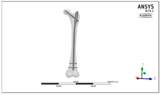
Figure 1.
The femoral cephalomedullary nail inside the femoral bone.
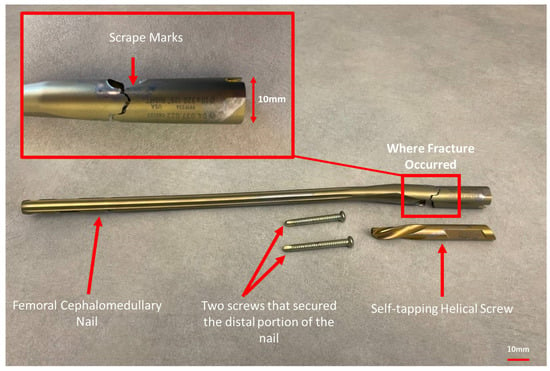
Figure 2.
The as-received femoral cephalomedullay nail showing the femoral cephalomedullary nail and where the fracture occurred, the scrape marks on the femoral nail, and the screws.
3. Physical Examination of the Failed Device
3.1. Visual Examination
The investigation of the failed femoral cephalomedullary nail device started with a visual examination of all the parts. Five parts were investigated separately: the two parts of the failed femoral cephalomedullary nail, the helical screw, and the two locking screws. The purpose of the visual examination was to catalog the parts and find areas of interest for more rigorous examination. The parts were visually inspected, and photographic evidence was collected.
3.2. Fractographic Examination
Optical and scanning electron microscopes were used to document the fracture surface characteristics such as extensive scratching, plastic deformation, rubbed surfaces, discoloration, and pitting, along with cleavage, cracking, deposits of debris, striations, and dimples. A PEMTRON scanning electron microscope (SEM PS-230, Seoul, Republic of Korea) 10 kv was used to perform the fractographic examination. A small portion of the failure surface was coated with silver (Ag) paint. This allowed for electron discharge from the specimen, to observe the surface under the scanning electron microscope.
3.3. Material Conformity
A qualitative metallographic analysis was performed based on ASME F620-00 and ASTM F2066-18 [,]. A sample from the femoral cephalomedullary nail was taken. Cutting, mounting, and polishing were performed to prepare the sample. The polishing was performed with different grades of silicon carbide papers (320–600 grit) and diamond abrasive solutions (9–0.01 μm). After the polishing, X-ray energy-dispersive spectroscopy (energy-dispersive X-ray analysis (EDS), Thermo Fisher Scientific, Hillsboro, OR, USA) was performed on the nail sample surface, and the results were compared with the ASTM standards ASME F620-00 and ASTM F2066-18 reported for Ti-15Motitanium alloy to ensure that there was no significant difference that might have caused the failure [,].
4. Computational Simulation Analysis of the Failed Device
Three-dimensional models of the femoral cephalomedullary nail, the helical screw, and two locking screws were constructed using SolidWorks (Dassault Systèmes SolidWorks Corp., Concord, MA, USA). The dimensions were measured from the submitted samples, Figure 2. The 3D model of the device is shown in Figure 3. The three-dimensional model of the femoral bone was modeled using Materialise Mimics 19.0 and 3-matic 13.0 software (Materialise, Leuven, Belgium), then imported into the SolidWorks program, and the cephalomedullary nail was inserted inside the femoral bone model. After modifying the model that composed of the bone and nail construct (shown in Figure 4), it was imported into ANSYS Workbench 19.2 (ANSYS Inc., Canonsburg, PA, USA) to simulate the loading conditions and regions of stress development. Regarding the meshing, the tetrahedral element type was applied in the current simulation. The finite element analysis meshing was automatically adapted through the Ansys program, where convergence tools were used with 5% convergence, and resulted in 31,945 Nodes and 17,856 Elements. The three-dimensional model of the femoral bone showing the meshing is presented in Figure 5. The meshing of the three-dimensional model of the femoral cephalomedullary nail, the helical screw, and the two cortical screws is shown in Figure 6.
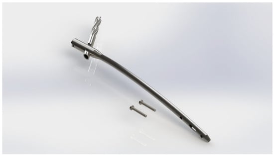
Figure 3.
The 3D model of the femoral CM nail, the self-taping helical screw, and two locking screws modeled using SolidWorks.
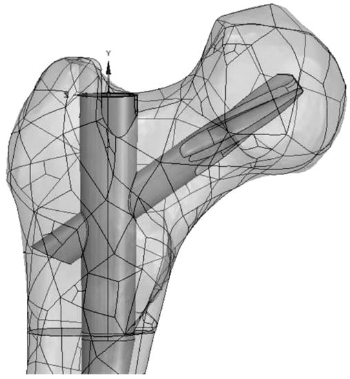
Figure 4.
The 3D model of the femoral CM nail inside the femoral bone.
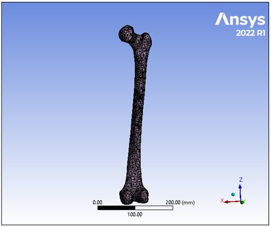
Figure 5.
The 3D model of the femoral bone showing the meshing with 31,945 nodes and 17,856 elements.
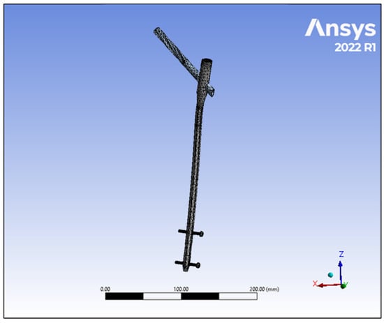
Figure 6.
The 3D model of the femoral CM nail, the helical screw, and the two cortical screws showing the meshing.
The material properties of the model were set such that the body of the nail was made of titanium alloy Ti-15Mo, while the helical screw and the two locking screws were made of Ti-6Al-7Nb. The material properties of titanium alloy Ti-15Mo that were imported in Ansys program to perform the simulation were 106 GPa modulus of elasticity, 0.3 Poisson’s ratio, 950 MPa ultimate tensile strength, 800 MPa 0.2% yield strength, hardness of 36 HRC, and 4.95 gm/cm3 density. The material properties of Ti-6Al-7Nb that were imported into the Ansys program to perform the simulation were 113 GPa modulus of elasticity, 0.32 Poisson’s ratio, 862 MPa ultimate tensile strength, and 4.52 gm/cm3 density. The material properties of the femoral bone were adapted from Hamandi, F. and Goswami, T. (2017), which provided the anisotropic material properties of the bone []. In that method, the mathematical relationship between Hounsfield’s units and density of the bone was imported into Mimics software to obtain the density. Then, the elastic and shear modulus were calculated in three different directions: radial, longitudinal, and circumferential []. The eighty material groups of the femoral bone, their densities, their nine elastic constants, and the elasticity tensor components are available in the supplementary material. The testing conditions were set such that the long shaft body of the femoral nail was set to be fixed, as this portion would be deeply embedded within the long bone of the femur, while some displacement was allowed for the locking screws along the x-axis. The loading was applied in two steps. The first step included the preload torque for the installation of the screws, and the second step included the axial loads and torque. The axial compression load of the normal human gait cycle during walking [] was applied at the femoral head, while 5 Nm torque was applied at the distal end of the femoral bone []. The body weight of the patient was assumed to be 80 kg in this study. However, it is important to mention that the load might reach more than 4 times the weight of the body with an abnormal gait cycle []. The contact analysis of the model was simulated by defining the target and contact surfaces between the nail and bone, the nail and screws, and bone and screws as no merge between components with load and deformation transformation among the bone, femoral nail, and the screws. The coefficient of friction between the femoral nail and the bone was considered as 0.4 [], and it was considered as 0.1 between the bone and the screws [] and 0.35 between the nail and the screws [].
5. Results
5.1. Visual Examination
Visual examination demonstrated that the femoral cephalomedullary nail fractured into two pieces (shown in Figure 2). After examining the different parts of the failed femoral nail, there seems to be likelihood of a number of different events. First, there is evidence of scrape marks on the self-tapping helical screw, which suggests that there might have been interference between the helical screw and the interior wall of the femoral cephalomedullary nail while being implanted within the body, as shown in Figure 7. Additionally, there is evidence of a fatigue shiny area, a good indicator of mechanical fatigue being present up to the point the device failed, as shown in Figure 8, where the crack initiation area, fatigue crack propagation, and the catastrophic rupture areas were identified. In addition, there is evidence of overloading failure mode. Based on the observed evidence, extensive deformation on the threads of the helical screw indicates that there may have been an interference, and the helical screw might have made contact with the interior wall of the femoral CM nail during the implanting process, causing some level of surface damage on both parts. It is possible that this surface damage on the cephalomedullary nail allowed for a surface crack to form. Through the regular loading that the nail undergoes, the surface crack would propagate due to the tension and shear stress on the surface of the CM nail. The propagation of cracks formed the striations seen on the failed device. This continued for a period of time up until the crack grew to the point where the structure of the cephalomedullary nail could no longer withstand the load and catastrophically failed in two pieces.
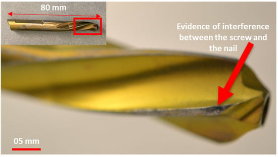
Figure 7.
Evidence of scrape marks on the self-tapping helical screw that suggests that may have been interference between the screw and the interior wall of the nail while being implanted within the body.
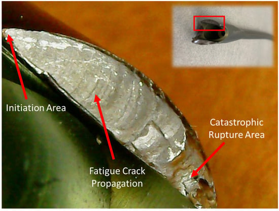
Figure 8.
Closer look at the fractured surface of the femoral CM nail showing the beach marks, a good indicator of mechanical fatigue, the crack initiation area, fatigue crack propagation, and the catastrophic rupture area.
5.2. Optical Microscopic Examination
The surface topology of the fracture surface of the femoral cephalomedullary nail was mapped with an optical microscope. There appears to be a microcrack located in the area before the fatigue damage starts. Figure 9 demonstrates the beach marks on the fracture surface and the rough overload failure area. It is possible that this microcrack could have started the crack propagation, leading to device failure. After the crack grew under fatigue loading, the device weakened to the point of total failure and needed to be removed from the patient.
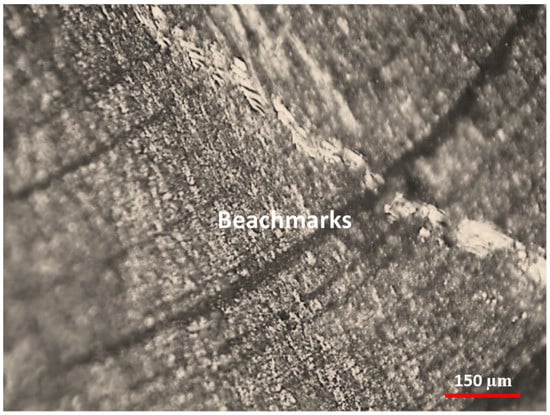
Figure 9.
Beach marks on the fracture surface.
5.3. Fractographic Examination
The characteristics of the fracture surface of the femoral nail were documented using a scanning electron microscope. Figure 10 demonstrates the failure surface of the CM nail illustrating the crack initiation, propagation, and final failure areas. Figure 11 indicates the topographical SEM image of the fracture surface of the cephalomedullary nail with beach marks, while the fracture failure is displayed in Figure 12. The investigation revealed the fracture initiation area, the fracture split area, and fracture surface striations, as demonstrated in Figure 13, Figure 14, and Figure 15, respectively. The fatigue striation spacing were measured and averaged 0.689 μm in length.
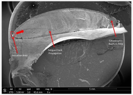
Figure 10.
The failure surface showing crack initiation, propagation, and final failure areas.
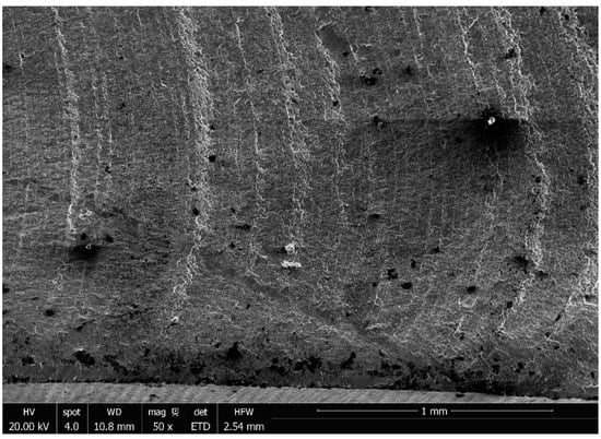
Figure 11.
Topographical SEM image of the fracture surface with beach marks.
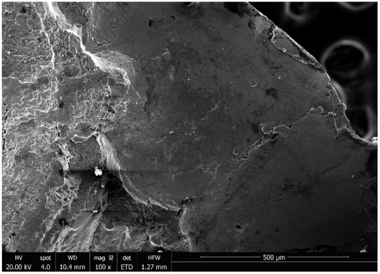
Figure 12.
Topographical SEM image of the fracture failure.
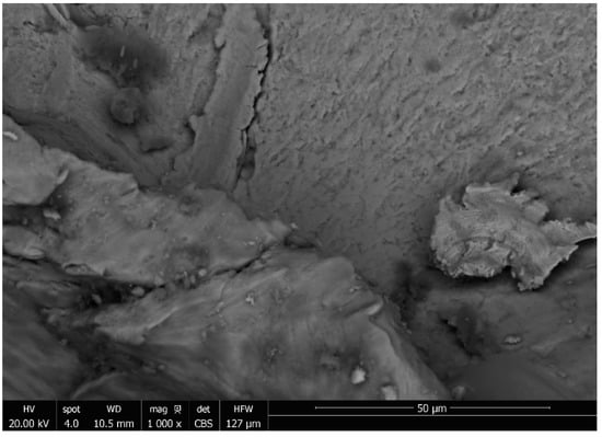
Figure 13.
Topographical SEM image of the fracture initiation area.
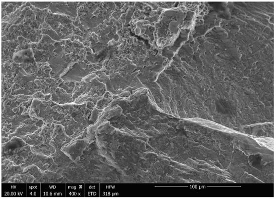
Figure 14.
Topographical SEM image of the fracture split area.
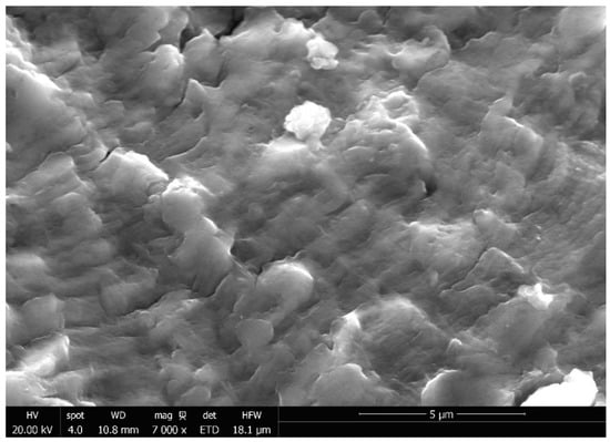
Figure 15.
Topographical SEM image of the fracture surface striations.
5.4. Material Conformity
According to ASME F620-00 and ASTM F2066-18 standards, metallographic qualitative analysis was performed in the current study. A polished sample of the femoral nail was investigated with X-ray energy-dispersive spectroscopy. According to the standards, the round implant bars such as the investigated cephalomedullary nail are made of Ti-15Mo titanium alloy in alpha plus beta annealed condition with a hardness of 32–38 HRC, 950 MPa ultimate tensile strength, 800 Mpa 0.2% yield strength, 4.95 gm/cm3 density, and 106 GPa modulus of elasticity.
The energy-dispersive X-ray analysis results are presented in Figure 16, and the figure shows the peaks of different element weight percentages in the femoral nail. The results were compared with ASME F620-00 and ASTM F2066-18 standards reported for Ti-15Mo titanium alloy to ensure that there was no significant difference that might have caused the failure. All the elemental compositions of Ti-15Mo were inconclusive when compared with the ASTM standards ASME F620-00 (Table 1).
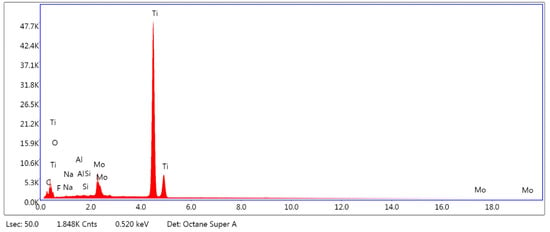
Figure 16.
The energy-dispersive X-ray spectrum results of the femoral CM nail made of Ti-15Mo titanium alloy in alpha plus beta annealed condition.

Table 1.
ASMT F2066-18 chemical requirements [].
Figure 17, Figure 18 and Figure 19 illustrate the electron backscatter diffraction (EBSD) findings (run on XL-30, 25 kv, spot size 5, 100 μm aperture). The orientation imaging microscopy (OIM) analysis was performed using Ti alpha and Ti beta patterns. Figure 17 shows EBSD band contrast maps, phase maps, and orientation maps of alpha and beta at low and high magnifications. Figure 18 shows EBSD band contrast maps, phase maps, and orientation maps of beta at low and high magnifications and alpha at high magnification. The figures demonstrate that the microstructure is predominantly Ti-beta phase, with some intergranular Ti-alpha phase, and the Ti-beta phase is very strongly textured. Additionally, grain size of the Ti-beta phase is in the order of 2–3 µm and represents 70.683% of the area fraction.
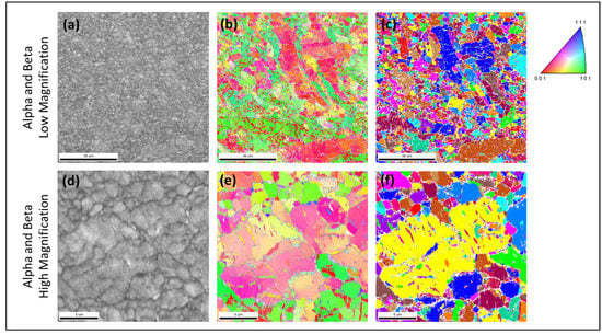
Figure 17.
Electron backscatter diffraction (EBSD) band contrast maps, phase maps, and orientation maps of alpha and beta. Low magnification (a–c) and high magnification (d–f).
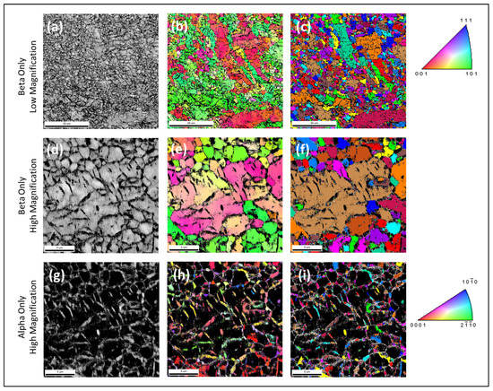
Figure 18.
Electron backscatter diffraction (EBSD) band contrast maps, phase maps, and orientation maps of beta low magnification (a–c), beta high magnification (d–f), and alpha high magnification (g–i).
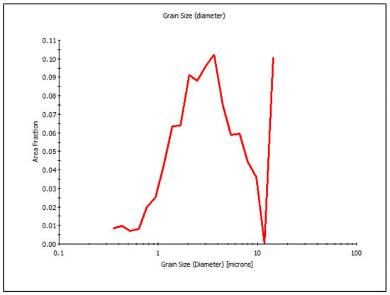
Figure 19.
Grain size (µm) with respect to area fraction.
5.5. Computational Simulations of Failures
The von Mises stress distribution in the femoral cephalomedullary nail inside the femoral bone was obtained, where the maximum von Mises stress was 1372.5 MPa. Figure 20 and Figure 21 demonstrate the von Mises stress distribution across the femoral bone and the femoral CM nail device. The data produced from the finite element analysis can provide a description of how fracture influences internal forces in the nail, using the weight of the average adult male, 800 N, and average torque experienced during walking, 5 Nm []. A normal femur could be expected to withstand up to 3900.83 N, 4.88 times the weight of the average adult male, before it fails []. The FEM showed that the maximum stresses were on the contact area between the femoral CM nail and the helical screw (shown in Figure 21). The loading alone could not have caused the failure. The ultimate tensile strength is 950 MPa and the fatigue strength is 240 MPa at 107 cycles, according to ASTM standards ASME F620-00 and ASTM F2066-18 [,]. It is likely that some initial damage occurred that allowed for a surface crack to form, and with the cyclic load of daily uses, the crack propagated until the device failed.
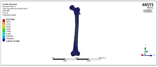
Figure 20.
The von Mises stress distribution across the femoral bone fixed with CM nail.
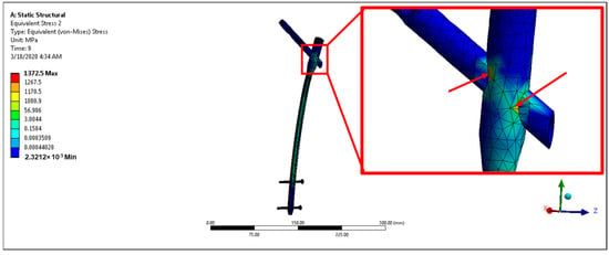
Figure 21.
The von Mises stress distribution across the femoral CM nail fixation device showing the maximum stress on the contact area between the femoral CM nail and the helical screw (red arrows).
6. Discussion
The clinical and the mechanical reasons responsible for the failure of a fractured femoral nailing system were investigated. The simple task of loading and unloading the femoral CM nail through regular cycles is likely not the initial cause of the failure. The cephalomedullary nail holds up well under regular loading conditions and would likely not cause a failure on its own. However, there is evidence to suggest that the nail could have taken some damage when the helical screw was inserted. It is entirely possible that the initial damage could have been the catalyst to propagate a surface fracture. Additionally, the optical and fractographic examinations demonstrated that there is evidence of fatigue striations, which is a good indicator of mechanical fatigue. In addition, the investigation showed that there is evidence of overloading failure mode.
The scanning electron microscope investigation demonstrated the failure surface of the femoral cephalomedullary nail illustrating the crack initiation, propagation, and final failure areas. Through the investigation, we were able to indicate the topographical area of the fracture surface of the CM nail with beach marks. The investigation revealed the fracture initiation area, the fracture split area, and fracture surface striations, which is a good indicator of mechanical fatigue. The fatigue striation spacing was measured, and averaged 0.689 μm in length. In addition, the investigation demonstrated that there is evidence of overloading failure mode. Based on the observed evidence, it is possible that during the implantation of the nail, there may have been interference between the helical screw and the interior wall of the femoral cephalomedullary nail, causing surface damage on both parts, and the surface damage on the CM nail allowed for a surface crack to form. Then, the surface crack would have propagated due to the tension and shear stress on the surface of the CM nail. The propagation of cracks formed the striations seen on the failed device. This continued for a period of time up until the crack grew to the point where the structure of the femoral cephalomedullary nail could no longer withstand the load and catastrophically failed. A similar failure was observed previously in a study on a tibiotalocalcaneal arthrodesis system that investigated the interference between the self-tapping helical screw and the nail during insertion as one of the factors that led to the failure of the implant [].
The metallographic qualitative analysis was performed based on ASME F620-00 and ASTM F2066-18 and reported for Ti-15Mo titanium alloy to ensure that there was no significant difference that might have caused the failure of the femoral CM nail. Orientation imaging microscopy (OIM) analysis was performed using Ti alpha and Ti beta patterns. The analysis demonstrates that the microstructure is predominantly Ti-beta phase, with some intergranular Ti-alpha phase, and the Ti-beta phase is very strongly textured. Additionally, the grain size of the Ti-beta phase is in the order of 2–3 µm and represents 70.683% of the area fraction. However, the chemical analysis was inconclusive, requiring more thorough testing in a third-party facility.
The finite element analysis provided a description of how fracture influences internal forces in the nail, using the weight of the average adult male, 800 N, and average torque experienced during walking. A normal femur could be expected to withstand up to 3900.83 N, 4.88 times the weight of the average adult male before it fails []. On the other hand, in an accompanying study, we investigated how having a subtrochanteric fracture caused the femur to only withstand approximately 1936 N, which is no more than 2.4 times the weight of the average adult male. Additionally, FEM showed that the maximum stresses were on the contact area between the nail and the helical screw. The loading alone could not have caused the failure. The ultimate tensile strength was 950 MPa and the fatigue strength was 240 MPa at 107 cycles. It is likely that some initial damage occurred that allowed for a surface crack to form, and with the cyclic load of daily use, the crack propagated until the device failed.
In general, the developed stresses would have not led to any plastic deformation, and some overload might be needed to cause premature failure of the femoral CM nail. As a result, by estimating the actual loading behavior of the nail from the activities of daily living of the individual, together with mechanical parameters, we can assume that the device might failed as a result of overload, or it is likely that some initial damage occurred that allowed for a surface crack to form, and with the cyclic load of daily use, the crack propagated until the device failed.
7. Conclusions
This current investigation utilized a combination of qualitative and quantitative analysis to determine the causes of failure of a medical device. The self-tapping helical screw likely had interference with the interior walls of the femoral nail during the implantation process. This is evident by the scrape marks on both the helical screw and the femoral nail. The analysis also showed the likelihood that the nail failed due to overloading the device after some period of mechanical fatigue. Scanning electron microscope analysis showed the propagation of an internal crack though cyclical loading, resulting in microscopic striations with fatigue striation spacing averaging 0.689 μm in length. There was also the characteristic of overloading failure occurring in several places along the fracture surface. Additionally, the computational simulation suggested that the loading alone could not have caused the failure, and it is likely that some initial damage occurred that allowed for a surface crack to form, and with the cyclic load of daily use, the crack propagated until the device failed. This suggests that the crack propagated to the point where a portion of the nail could no longer withstand the internal force generated during use. At this point, that portion of the device was overloaded and failed.
Supplementary Materials
The following supporting information can be downloaded at: https://www.mdpi.com/article/10.3390/met13030506/s1.
Author Contributions
Conceptualization, F.H. and T.G.; methodology, G.S., S.W. and F.H.; software, S.W. and F.H.; validation, S.W., F.H. and T.G.; investigation, G.S., S.W. and F.H.; resources, I.V. and G.S.; data curation, I.V.; writing—original draft preparation, S.W. and F.H.; writing—review and editing, T.G.; visualization, F.H.; project administration, T.G. and I.V. All authors have read and agreed to the published version of the manuscript.
Funding
This research received no external funding.
Data Availability Statement
The data presented in this study are available in supplementary material here.
Conflicts of Interest
The authors declare no conflict of interest.
References
- Centers for Disease Control and Prevention. Home and recreational safety. In Falls Among Older Adults: Hip Fractures among Older Adults; Centers for Disease Control and Prevention: Atlanta, FA, USA, 2018. [Google Scholar]
- Sing, C.-W.; Lin, T.-C.; Bartholomew, S.; Bell, J.S.; Bennett, C.; Beyene, K.; Bosco-Lévy, P.; Chan, A.H.Y.; Chandran, M.; Cheung, C.-L.; et al. Global epidemiology of hip fractures: A study protocol using a common analytical platform among multiple countries. BMJ Open 2021, 11, e047258. [Google Scholar] [CrossRef] [PubMed]
- Parker, M.J.; White, A.; Boyle, A. Fixation versus hemiarthroplasty for undisplaced intracapsular hip fractures. Injury 2008, 39, 791–795. [Google Scholar] [CrossRef] [PubMed]
- Adedapo, A.; Ikpeme, J. The results of internal fixation of three-and four-part proximal humeral fractures with the polarus nail. Injury 2001, 32, 115–121. [Google Scholar] [CrossRef] [PubMed]
- Gaines, R.W., Jr. The use of pedicle-screw internal fixation for the operative treatment of spinal disorders. J. Bone Jt. Surg. 2000, 82, 1458–1476. [Google Scholar] [CrossRef] [PubMed]
- Winquist, R.A.; Hansen, S.T., Jr. Comminuted fractures of the femoral shaft treated by intramedullary nailing. Orthop. Clin. N. Am. 1980, 11, 633–648. [Google Scholar] [CrossRef]
- White, G.M.; Healy, W.L.; Brumback, R.J.; Burgess, A.R.; Brooker, A.F. The treatment of fractures of the femoral shaft with the Brooker-Wills distal locking intramedullary nail. J. Bone Jt. Surg. 1986, 68, 865–876. [Google Scholar] [CrossRef]
- Frumberg, D.B.; Van Lanen-Wanek, D.J.; Jauregui, J.J.; Nadarajah, V.; Illical, E.M. Can flexible intramedullary nails provide proper fixation of long bone fractures in patients weighing over 100 pounds? J. Orthop. Trauma Rehabil. 2019, 26, 9–13. [Google Scholar] [CrossRef]
- Wheeless, C.R. Wheeless’ Textbook of Orthopaedics; Duke University Medical Center: Durham, NC, USA, 2001. [Google Scholar]
- Muminagic, S.N. History of Bone Fracture: Treatment and Immobilization. Mater. Socio Med. 2011, 23, 111. [Google Scholar] [CrossRef]
- Schatzker, J.; Tile, M.; Axelrod, T.S. The Rationale of Operative Fracture Care; Springer: Berlin/Heidelberg, Germany, 2005; Volume 24, pp. 385–407. [Google Scholar]
- Hernández, J.L.; Olmos, J.M.; Alonso, M.A.; González-Fernández, C.R.; Martínez, J.; Pajarón, M.; Llorca, J.; González-Macías, J. Trend in hip fracture epidemiology over a 14-year period in a Spanish population. Osteoporos. Int. 2006, 17, 464–470. [Google Scholar] [CrossRef] [PubMed]
- Seo, J.-S.; Min, H.-J.; Kim, D.M.; Oh, S.-M.; Kim, S.-M. Surgical Results of the Cephalomedullary Nail for the Femoral Intertrochanteric Fracture: Comparison between Non-experienced Surgeons and Experienced Surgeon. Hip Pelvis 2016, 28, 225–231. [Google Scholar] [CrossRef] [PubMed]
- ASTM F2066-18; Standard Specification for Wrought Titanium-15 Molybdenum Alloy for Surgical Implant Applications (UNS R58150). ASTM International: West Conshohocken, PA, USA, 2018. Available online: www.astm.org (accessed on 20 May 2019).
- ASTM F620-00; Standard Specification for Alpha Plus Beta Titanium Alloy Forgings for Surgical Implants. ASTM International: West Conshohocken, PA, USA, 2000. Available online: www.astm.org (accessed on 20 May 2019).
- Hamandi, F.; Goswami, T. Macrodamage Accumulation Model for a Human Femur. Appl. Bionics Biomech. 2017, 2017, 4539178. [Google Scholar] [CrossRef] [PubMed]
- Bergmann, G. HIP98, Loading of the Hip Joint; Compact Disc, Freie Universität Berlin: Berlin, Germany, 2001. [Google Scholar]
- Hamandi, F.; Whitney, A.; Stouffer, M.H.; Prayson, M.J.; Rittweger, J.; Goswami, T. Cyclic Damage Accumulation in the Femoral Constructs Made With Cephalomedullary Nails. Front. Bioeng. Biotechnol. 2021, 8, 593609. [Google Scholar] [CrossRef] [PubMed]
- Hamandi, F.; Laughlin, R.; Goswami, T. Failure analysis of PHILOS plate construct used for pantalar arthrodesis Paper II—Screws and FEM simulations. Metals 2018, 8, 279. [Google Scholar] [CrossRef]
- Perren, S.M. Evolution of the internal fixation of long bone fractures. The scientific basis of biological internal fixation: Choosing a new balance between stability and biology. J. Bone Jt. Surg. 2002, 84, 1093–1110. [Google Scholar] [CrossRef]
- Goswami, T.; Gundapaneni, D.; Slocum, M.; Paul, P.; Christof, S. Failure investigation of a tibiotalocalcaneal arthrodesis system. Eng. Fail. Anal. 2016, 59, 588–604. [Google Scholar] [CrossRef]
Disclaimer/Publisher’s Note: The statements, opinions and data contained in all publications are solely those of the individual author(s) and contributor(s) and not of MDPI and/or the editor(s). MDPI and/or the editor(s) disclaim responsibility for any injury to people or property resulting from any ideas, methods, instructions or products referred to in the content. |
© 2023 by the authors. Licensee MDPI, Basel, Switzerland. This article is an open access article distributed under the terms and conditions of the Creative Commons Attribution (CC BY) license (https://creativecommons.org/licenses/by/4.0/).