

Effect of Deep Cryogenic Treatment on Wear Behavior of Cold Work Tool Steel


Abstract
:1. Introduction
2. Experimental Work
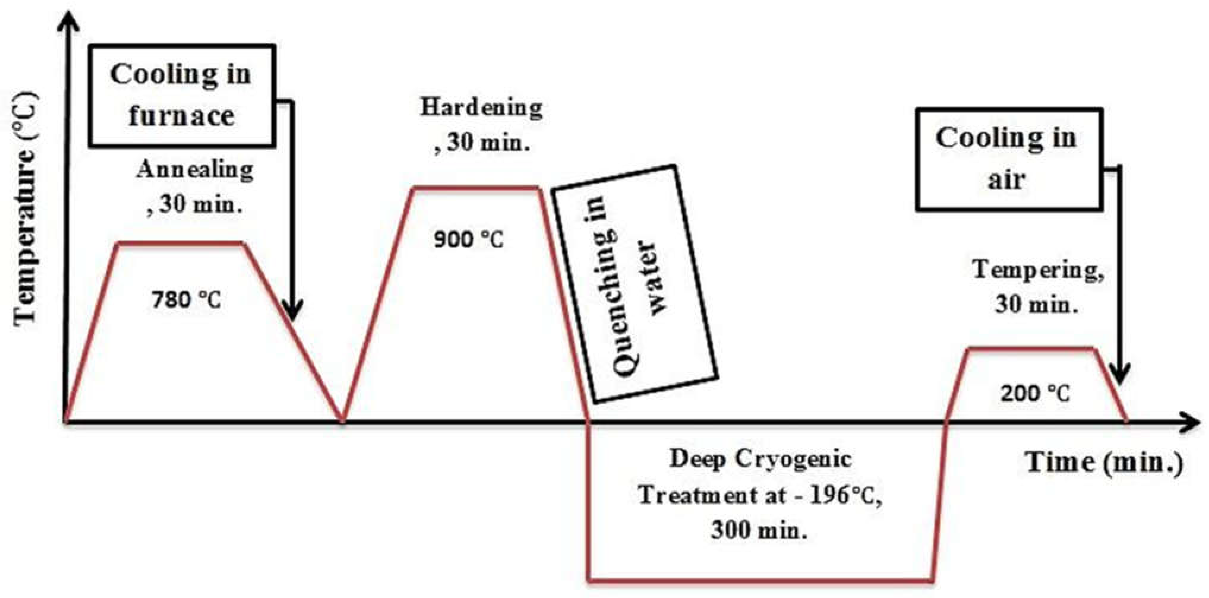
2.1. Materials and Heat Treatment
2.2. Microstructure
2.3. Hardness and Impact Test
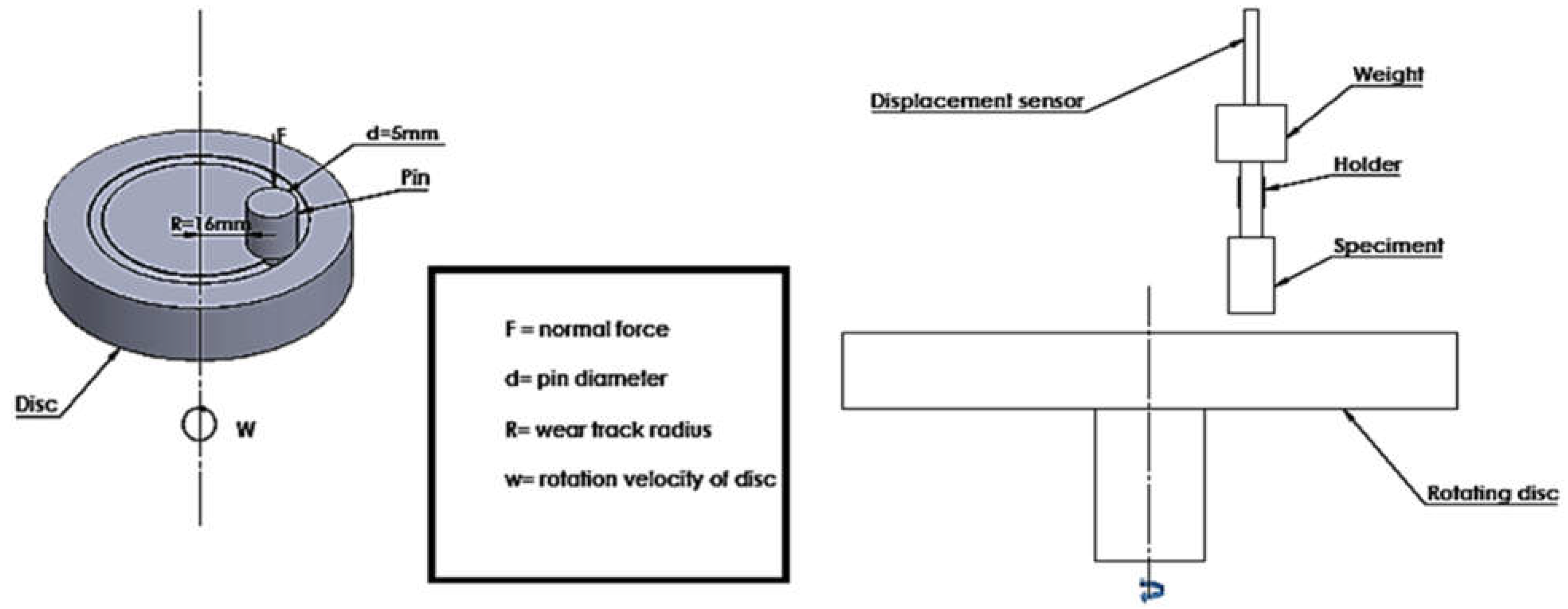
2.4. Wear Test
3. Results and Discussions
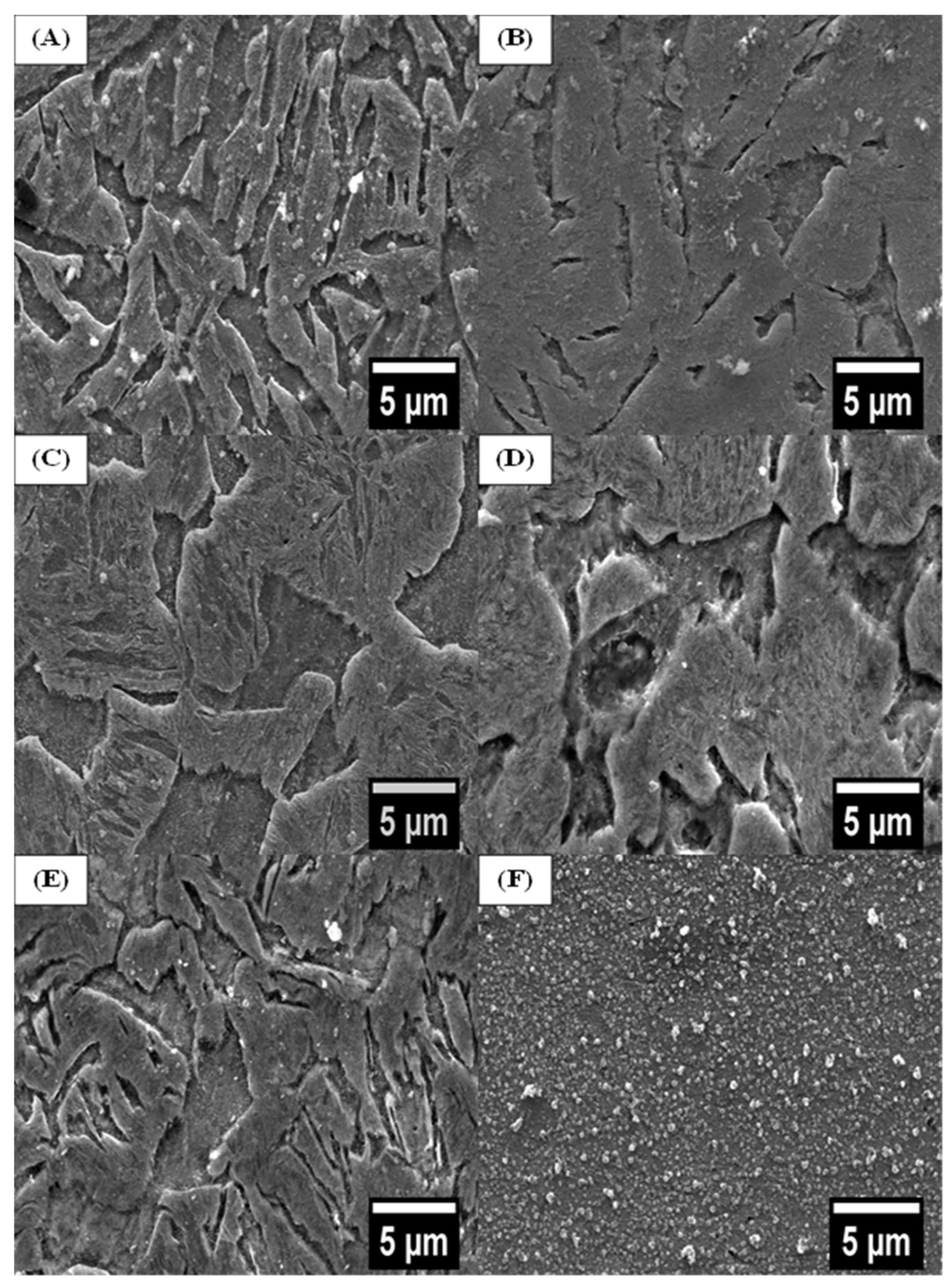
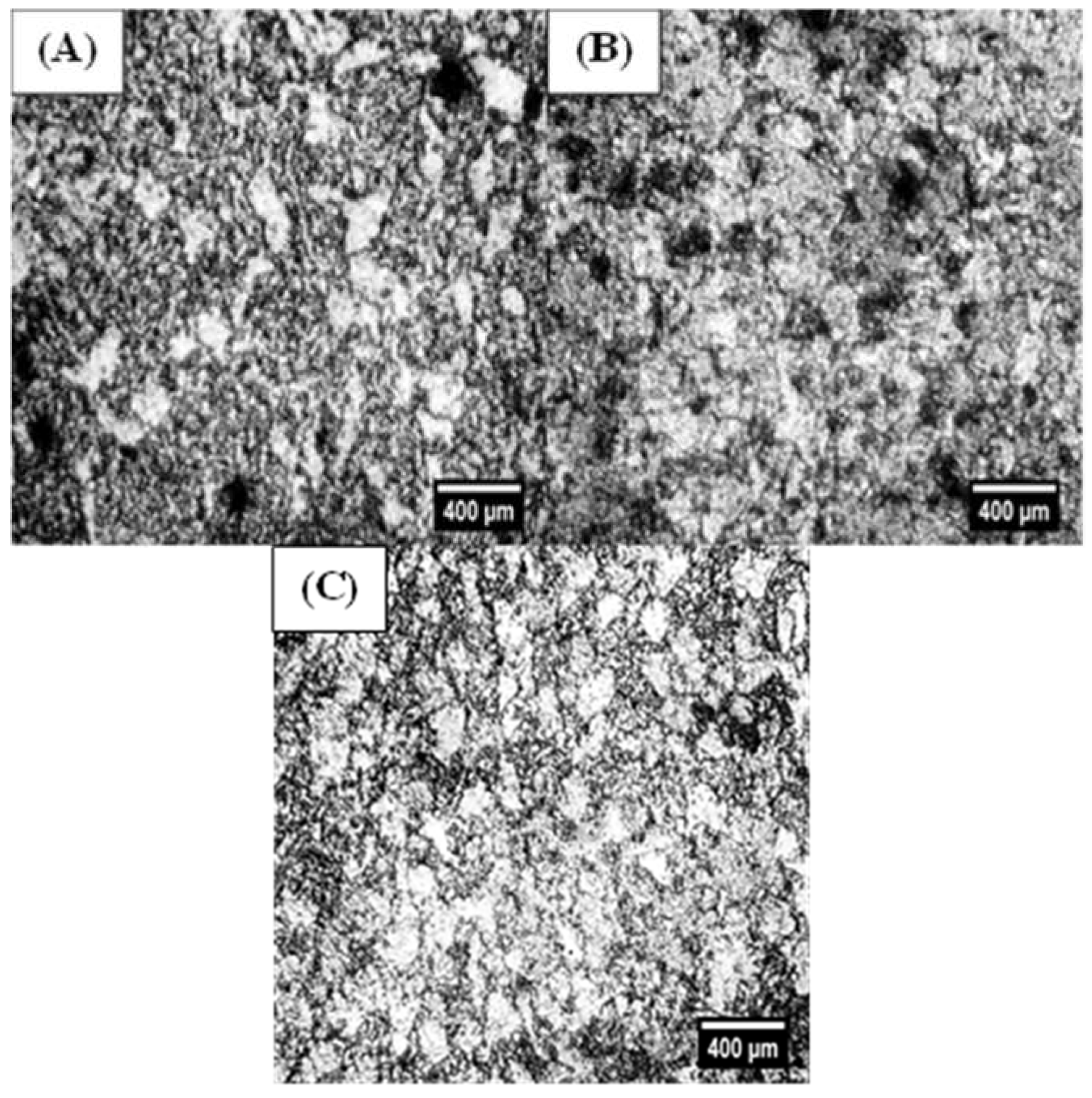
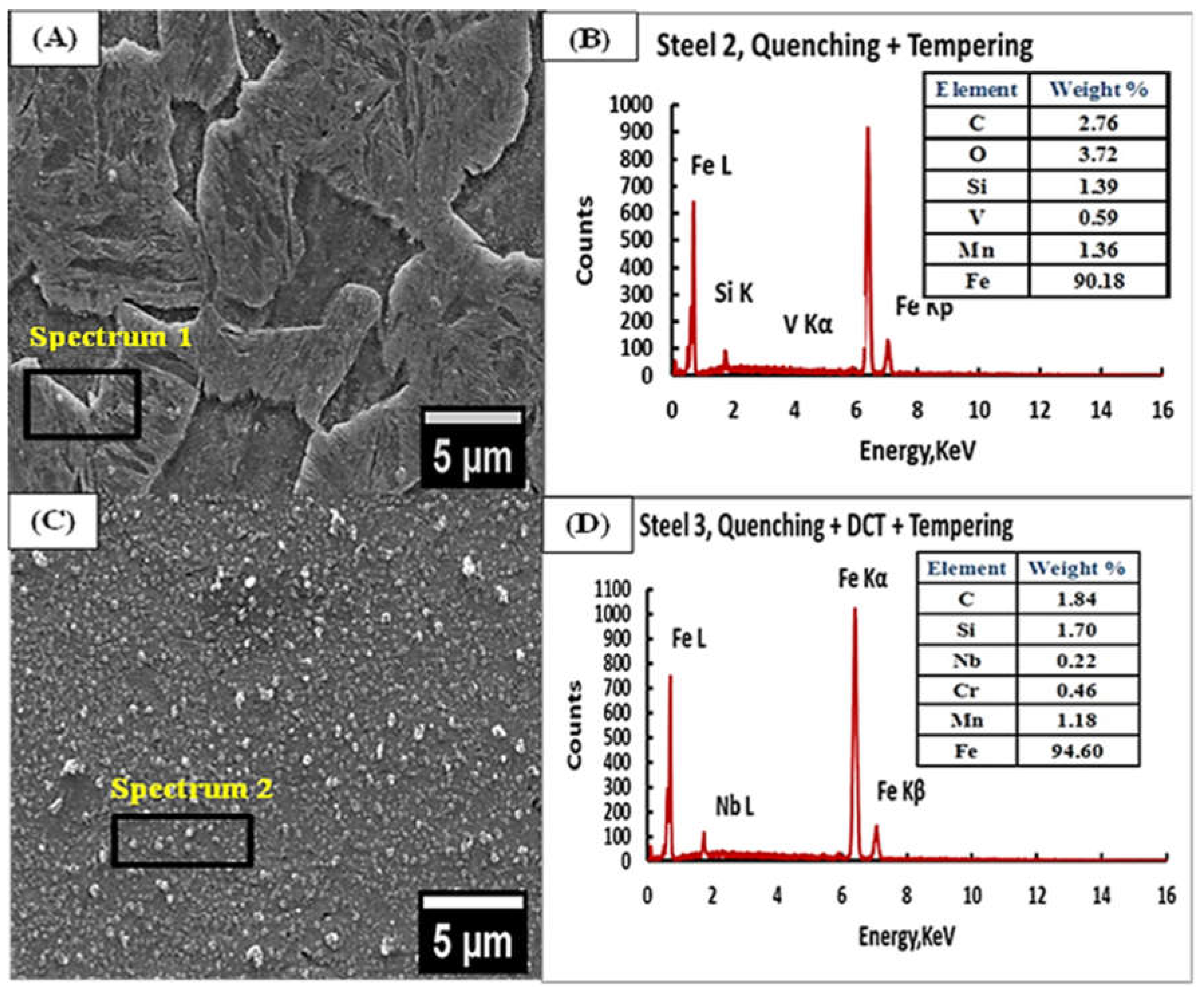
3.1. Microstructure Analysis
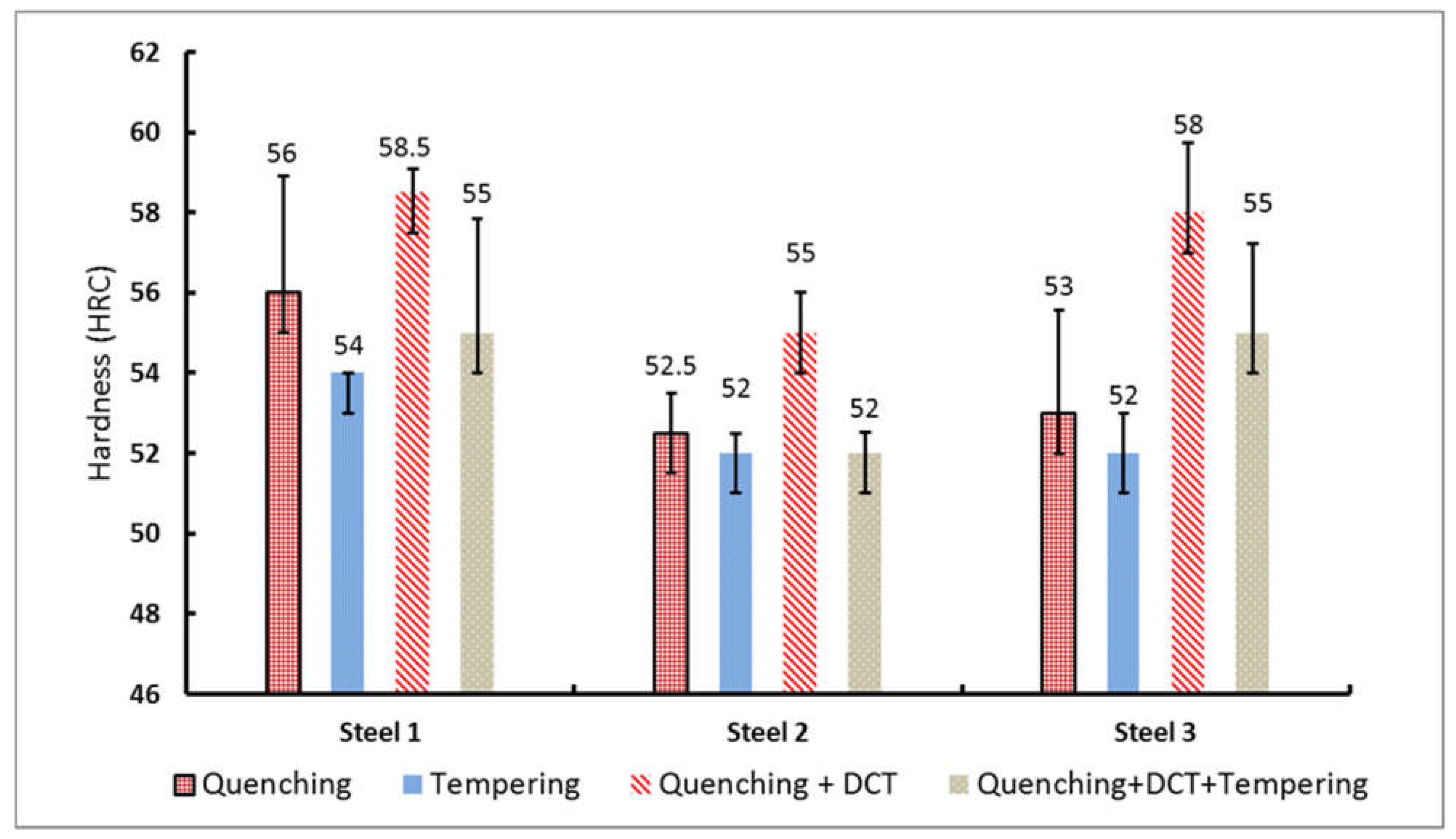
3.2. HRC Hardness
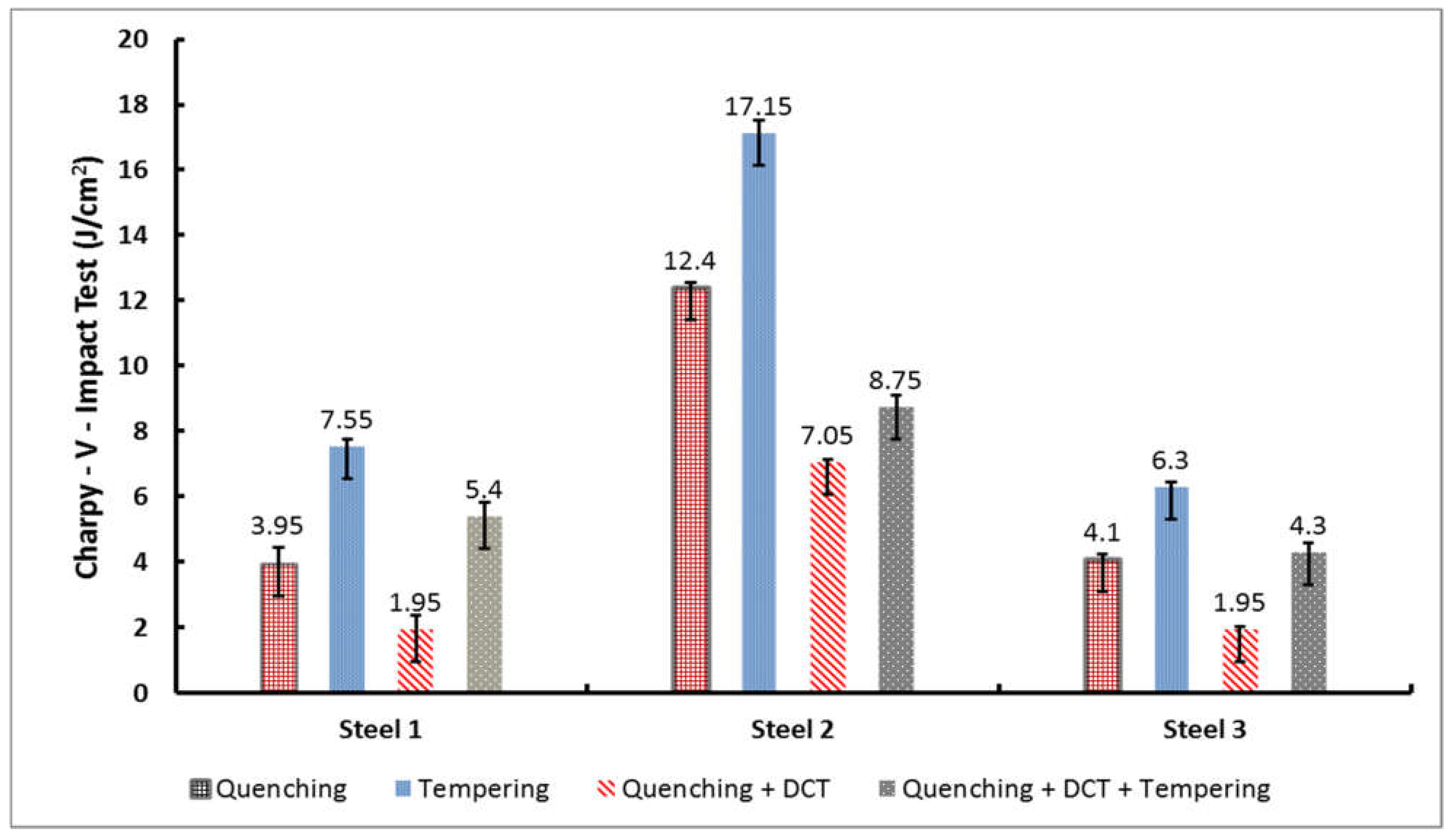
3.3. Impact Energy
3.4. Wear Behavior
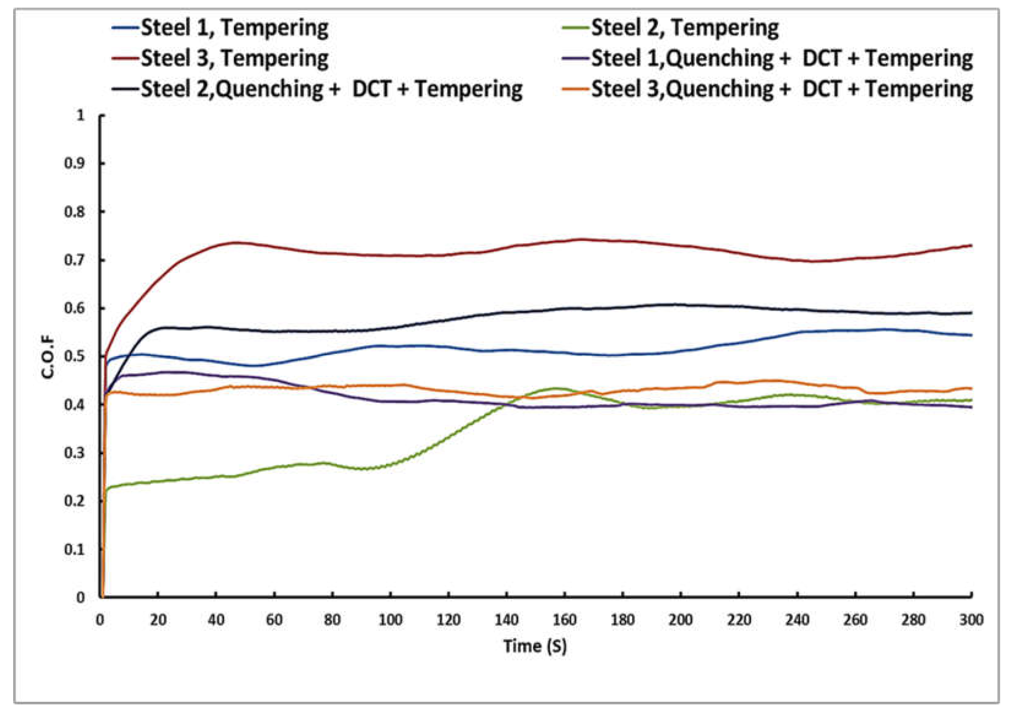
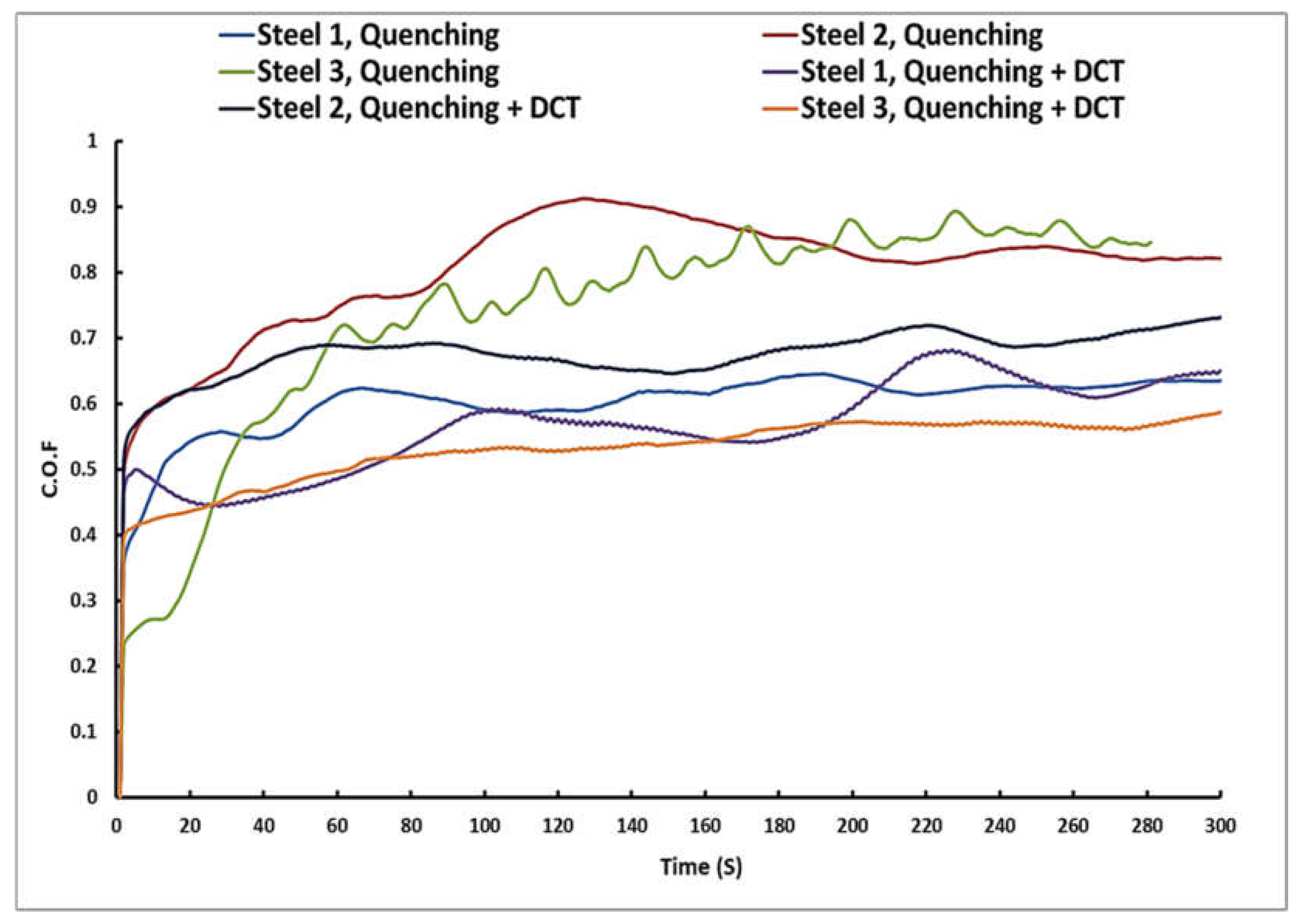
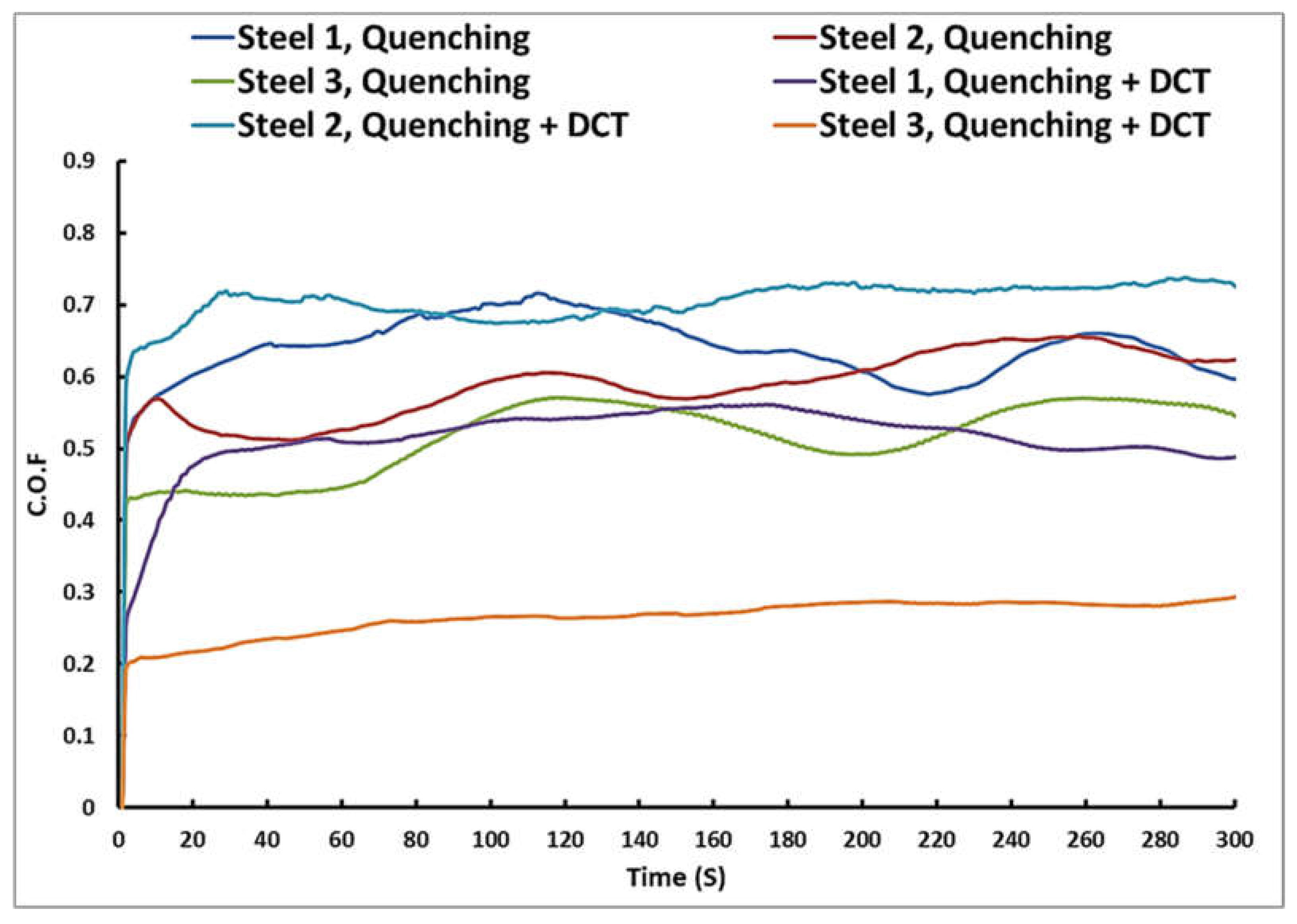
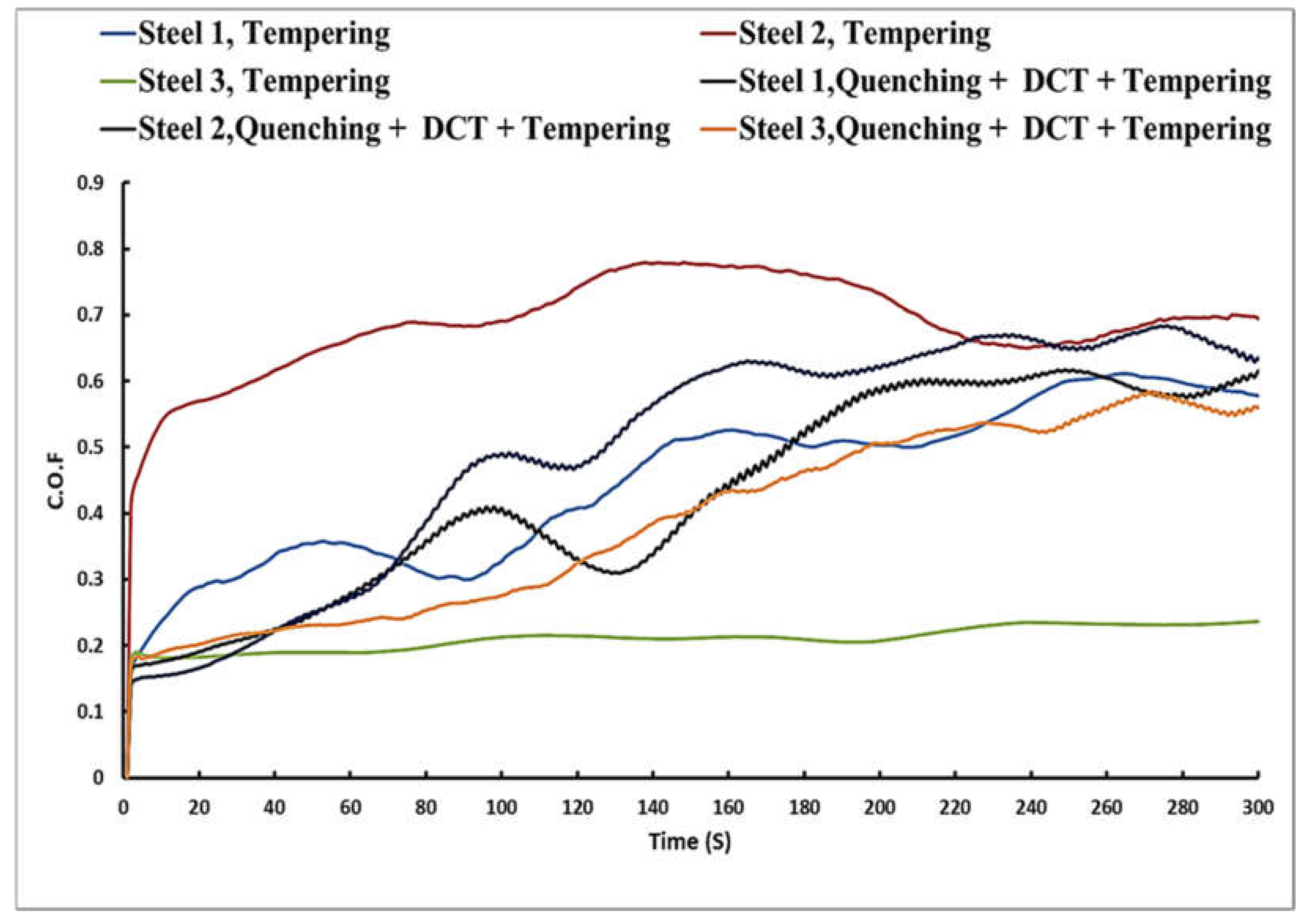
3.4.1. Friction Coefficient
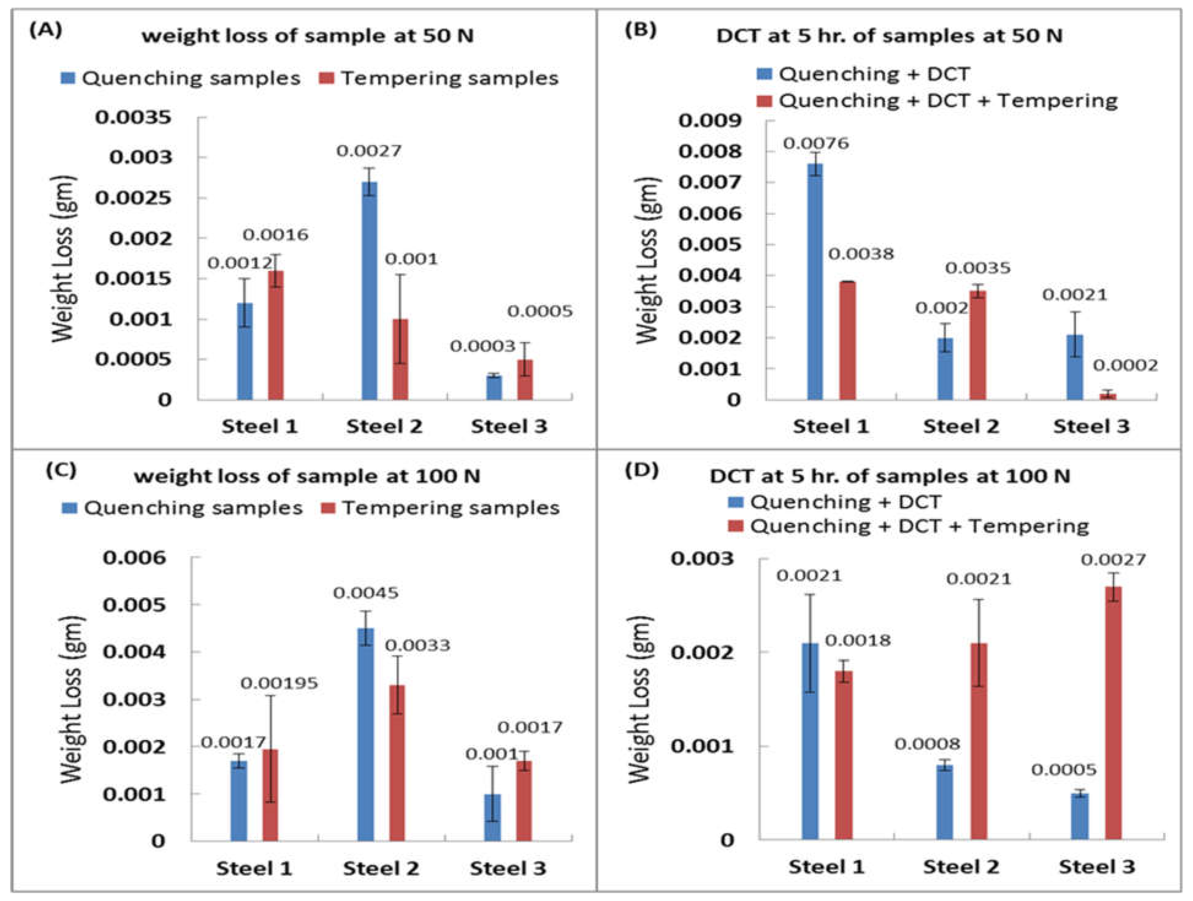
3.4.2. Weight Loss
3.4.3. Average Coefficient of Friction
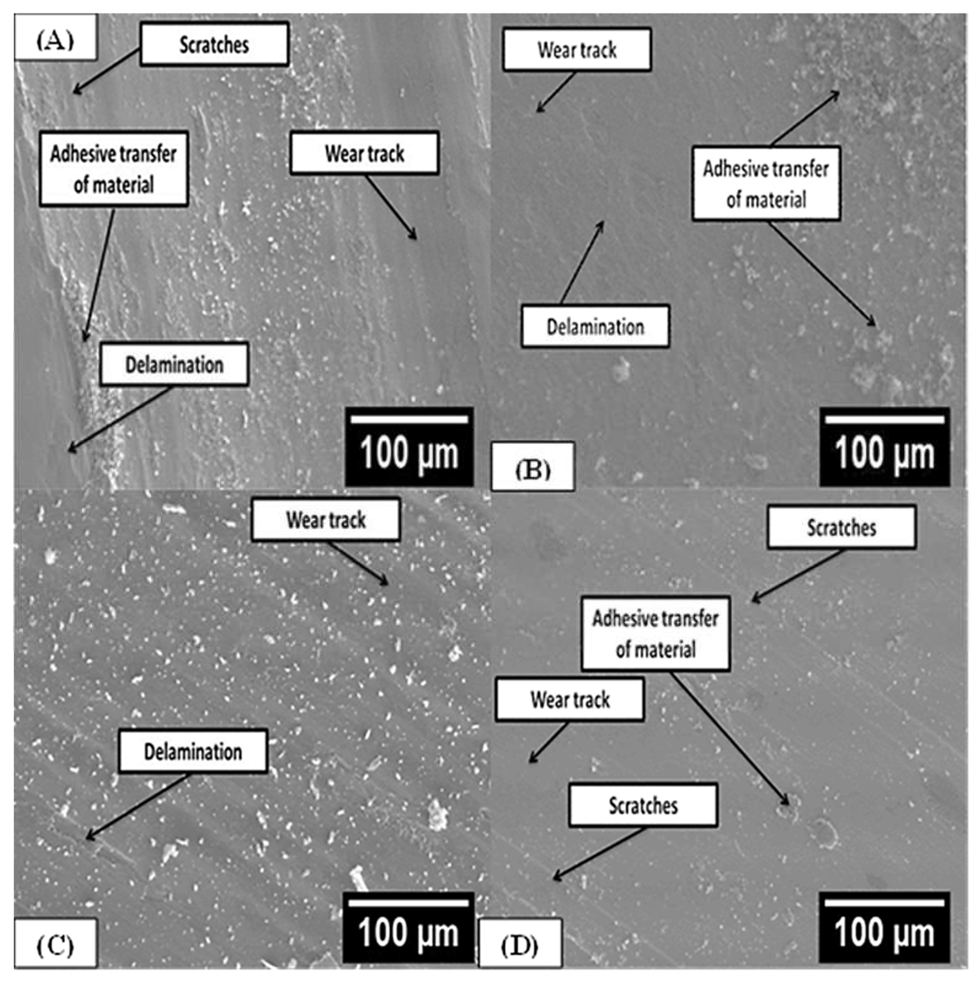
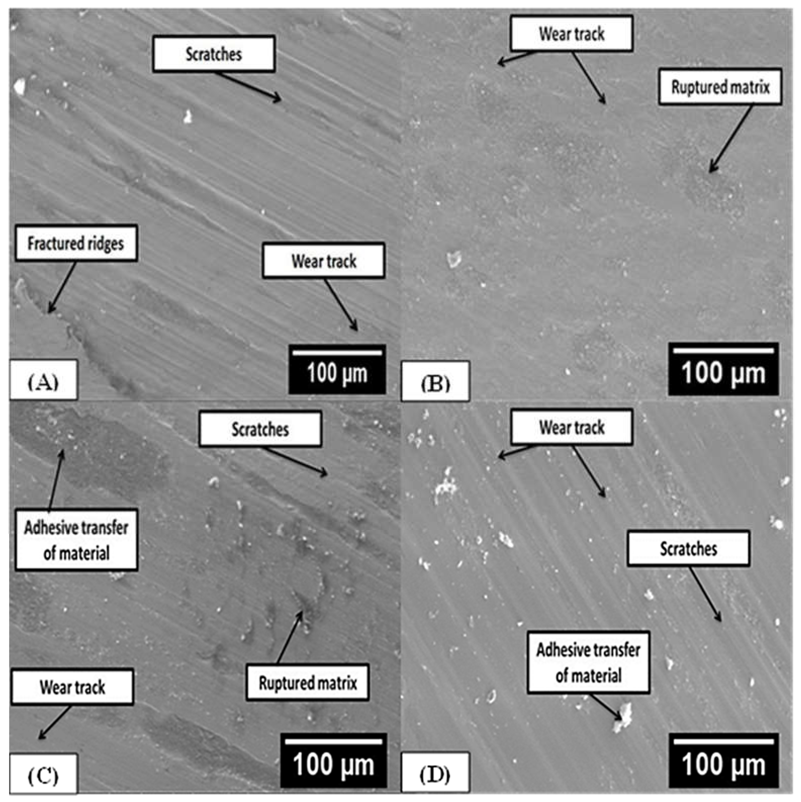
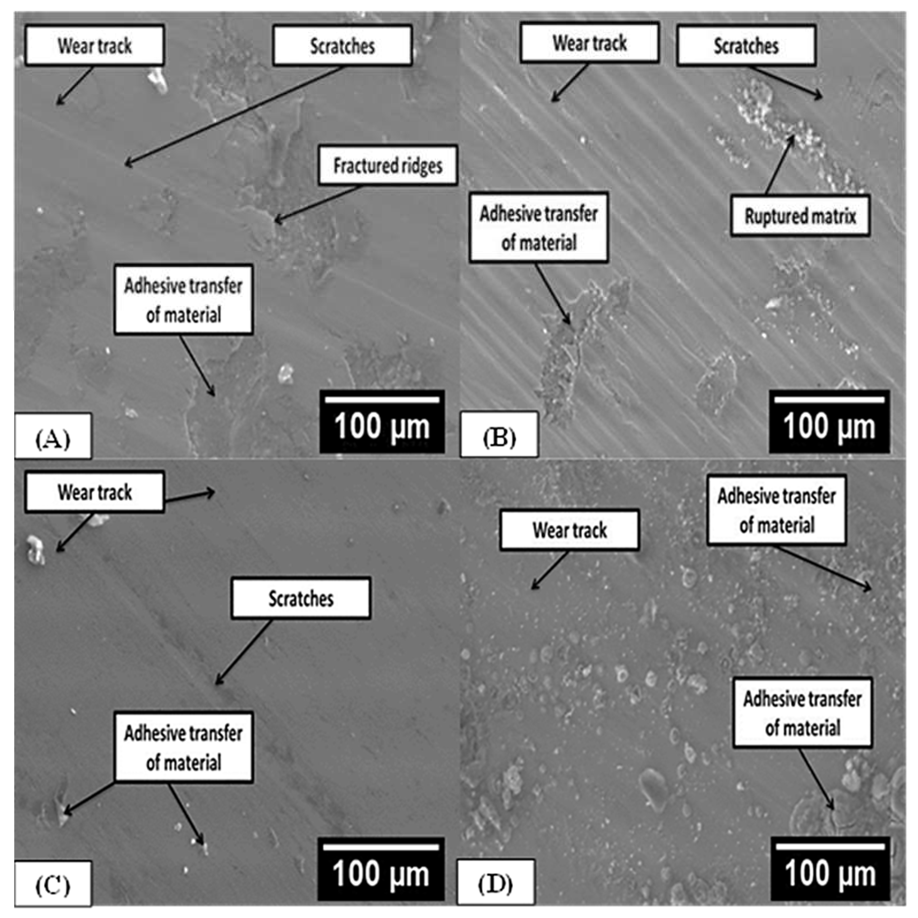
3.4.4. Worn Surfaces Analysis
4. Conclusions
- According to the scanning electron microscope, it can be concluded that the main microstructures of the tested samples were tempered martensite and retained austenite.
- The microstructure of the samples after exposure to deep cryogenic treatment is fine compared to conventional treatment.
- The as-quenched hardness for all steels is more than 54 HRC, and almost no change was observed in the hardness after tempering. However, the impact toughness was reduced after tempering by 30 to 45% due to the transformation of retained austenite to tempered martensite.
- Maximum hardness (HRC) was achieved at quenching + DCT for steel 1, which was recorded at 58.5. In contrast, the minimum hardness was measured for two steel samples (2 and 3) at tempering treatment conditions equal to 52 HRC.
- The friction coefficient at 50 N loads has approximate behavior for all tested samples for both conventional and deep cryogenic treatment, except that samples of steel 3 at hardening treatment conditions have higher fluctuations in the coefficient of friction.
- The coefficient of friction has higher fluctuations for conventional heat treatment in steel 3 samples with niobium (Nb) addition as a carbide forming element at both loads of 50 N and 100 N.
- Steel 3 specimens with DCT + tempering conditions achieved the lowest weight loss at a load of 50 N, with a value of 0.0002 gm. Steel 3 specimens with a hardening + DCT condition, on the other hand, achieved the lowest weight loss at a load of 100 N with a value of 0.0005 gm.
- Analysis of worn-out surfaces indicates that the predominant wear mechanism is adhesive wear for both applied loads, and after applying DCT, the adhesive wear mechanism decreased due to both retained austenite transformation to tempered martensite and fine precipitation of carbides.
Author Contributions
Funding
Data Availability Statement
Conflicts of Interest
References
- Toboła, D.; Brostow, W.; Czechowski, K.; Rusek, P. Improvement of wear resistance of some cold working tool steels. Wear 2017, 382–383, 29–39. [Google Scholar] [CrossRef]
- Podgornik, B.; Majdic, F.; Leskovsek, V.; Vizintin, J. Improving tribological properties of tool steels through combination of deep-cryogenic treatment and plasma nitriding. Wear 2012, 288, 88–93. [Google Scholar] [CrossRef]
- Gåård, A.; Krakhmalev, P.; Bergström, J. Wear mechanisms in deep drawing of carbon steel–correlation to laboratory testing. Tribotest 2008, 14, 1–9. [Google Scholar] [CrossRef]
- Bahrami, A.; Anijdan, S.H.M.; Golozar, M.A.; Shamanian, M.; Varahram, N. Effects of conventional heat treatment on wear resistance of AISI H13 tool steel. Wear 2005, 258, 846–851. [Google Scholar] [CrossRef]
- Bourithis, L.; Papadimitriou, G.; Sideris, J. Comparison of wear properties of tool steels AISI D2 and O1 with the same hardness. Tribol. Int. 2006, 39, 479–489. [Google Scholar] [CrossRef]
- Staia, M.H.; Pérez-Delgado, Y.; Sanchez, C.; Castro, A.; Le Bourhis, E.; Puchi-Cabrera, E.S. Hardness properties and high-temperature wear behavior of nitrided AISI D2 tool steel, prior and after PAPVD coating. Wear 2009, 267, 1452–1461. [Google Scholar] [CrossRef]
- Muro, M.; Artola, G.; Gorriño, A.; Angulo, C. Wear and Friction Evaluation of Different Tool Steels for Hot Stamping. Adv. Mater. Sci. Eng. 2018, 2018, 3296398. [Google Scholar] [CrossRef]
- Barrau, O.; Boher, C.; Gras, R.; Rezai-Aria, F. Analysis of the friction and wear behaviour of hot work tool steel for forging. Wear 2003, 255, 1444–1454. [Google Scholar] [CrossRef]
- King, P.C.; Reynoldson, R.W.; Brownrigg, A.; Long, J.M. Pin on disc wear investigation of nitrocarburised H13 tool steel. Surf. Eng. 2013, 21, 99–106. [Google Scholar] [CrossRef]
- Drozd, K.; Walczak, M.; Szala, M.; Gancarczyk, K. Tribological Behavior of AlCrSiN-Coated Tool Steel K340 Versus Popular Tool Steel Grades. Materials 2020, 13, 4895. [Google Scholar] [CrossRef]
- Brezinová, J.; Viňáš, J.; Guzanová, A.; Živčák, J.; Brezina, J.; Sailer, H.; Vojtko, M.; Džupon, M.; Volkov, A.; Kolařík, L.; et al. Selected Properties of Hardfacing Layers Created by PTA Technology. Metals 2021, 11, 134. [Google Scholar] [CrossRef]
- Holmberg, K.; Matthews, A. Coatings Tribology: Properties, Mechanisms, Techniques and Applications in Surface Engineering; Elsevier: Amsterdam, The Netherlands, 2009. [Google Scholar]
- So, H.; Yu, D.; Chuang, C. Formation and wear mechanism of tribo-oxides and the regime of oxidational wear of steel. Wear 2002, 253, 1004–1015. [Google Scholar] [CrossRef]
- Quinn, T.; Sullivan, J.; Rowson, D. Origins and development of oxidational wear at low ambient temperatures. Wear 1984, 94, 175–191. [Google Scholar] [CrossRef]
- Ueda, M.; Uchino, K.; Kobayashi, A. Effects of carbon content on wear property in pearlitic steels. Wear 2002, 253, 107–113. [Google Scholar] [CrossRef]
- Goto, H.; Amamoto, Y. Effect of varying load on wear resistance of carbon steel under unlubricated conditions. Wear 2003, 254, 1256–1266. [Google Scholar] [CrossRef]
- Lin, Y.; Wang, S.; Chen, T. A study on the wear behavior of hardened medium carbon steel. J. Mater. Process. Technol. 2002, 120, 126–132. [Google Scholar] [CrossRef]
- Krbata, M.; Eckert, M.; Majerik, J.; Barenyi, I. Wear Behaviour of High Strength Tool Steel 90MnCrV8 in Contact with Si3N4. Metals 2020, 10, 756. [Google Scholar] [CrossRef]
- Cora, Ö.N.; Namiki, K.; Koç, M. Wear performance assessment of alternative stamping die materials utilizing a novel test system. Wear 2009, 267, 1123–1129. [Google Scholar] [CrossRef]
- Hardell, J.; Hernandez, S.; Mozgovoy, S.; Pelcastre, L.; Courbon, C.; Prakash, B. Effect of oxide layers and near surface transformations on friction and wear during tool steel and boron steel interaction at high temperatures. Wear 2015, 330, 223–229. [Google Scholar] [CrossRef]
- Jalil, S.; Ghayour, H.; Amini, K.; Gharavi, F. The Effect of Deep Cryogenic Treatment on Microstructure and Wear Behavior of H11 Tool Steel. Phys. Met. Metallogr. 2019, 120, 888–897. [Google Scholar] [CrossRef]
- Kumar, S.; Nagraj, M.; Bongale, A.; Khedkar, N. Deep Cryogenic Treatment of AISI M2 Tool Steel and Optimisation of Its Wear Characteristics Using Taguchi‘s Approach. Arab. J. Sci. Eng. 2018, 43, 4917–4929. [Google Scholar] [CrossRef]
- Priyadarshini, M.; Behera, A.; Biswas, C.K. Effect of sub-zero temperatures on wear resistance of AISI P20 tool steel. J. Braz. Soc. Mech. Sci. Eng. 2020, 42, 212. [Google Scholar] [CrossRef]
- Collins, D.N. Deep Cryogenic Treatment of Tool Steels: A Review. Heat Treat. Met. 1996, 2, 8975829. [Google Scholar]
- Akhbarizadeh, A.; Shafyei, A.; Golozar, M. Effects of cryogenic treatment on wear behavior of D6 tool steel. Mater. Des. 2009, 30, 3259–3264. [Google Scholar] [CrossRef]
- Amini, K.; Akhbarizadeh, A.; Javadpour, S. Effect of deep cryogenic treatment on the formation of nano-sized carbides and the wear behavior of D2 tool steel. Int. J. Miner. Metall. Mater. 2012, 19, 795–799. [Google Scholar] [CrossRef]
- Deng, L.; Mozgovoy, S.; Hardell, J.; Prakash, B.; Oldenburg, M. Press-hardening thermo-mechanical conditions in the contact between blank and tool. Proceedings of International Conference on Hot Sheet Metal Forming of High-Performance Steel: 09/06/2013-12/06/2013, Luleå, Sweden, 9–12 June 2013; pp. 293–300. [Google Scholar]
- Ghiotti, A.; Bruschi, S.; Borsetto, F. Tribological characteristics of high strength steel sheets under hot stamping conditions. J. Mater. Process. Technol. 2011, 211, 1694–1700. [Google Scholar] [CrossRef]
- Das, D.; Dutta, A.K.; Ray, K.K. Influence of varied cryotreatment on the wear behavior of AISI D2 steel. Wear 2009, 266, 297–309. [Google Scholar] [CrossRef]
- Das, D.; Dutta, A.; Toppo, V.; Ray, K. Effect of deep cryogenic treatment on the carbide precipitation and tribological behavior of D2 steel. Mater. Manuf. Process. 2007, 22, 474–480. [Google Scholar] [CrossRef]
- Singh, K.; Khatirkar, R.K.; Sapate, S.G. Microstructure evolution and abrasive wear behavior of D2 steel. Wear 2015, 328–329, 206–216. [Google Scholar] [CrossRef]
- Jovičević-Klug, P.; Sedlaček, M.; Jovičević-Klug, M.; Podgornik, B. Effect of Deep Cryogenic Treatment on Wear and Galling Properties of High-Speed Steels. Materials 2021, 14, 7561. [Google Scholar] [CrossRef]
- Das, D.; Dutta, A.K.; Ray, K.K. Sub-zero treatments of AISI D2 steel: Part I. Microstructure and hardness. Mater. Sci. Eng. A 2010, 527, 2182–2193. [Google Scholar] [CrossRef]
- Das, D.; Dutta, A.; Ray, K. Correlation of microstructure with wear behaviour of deep cryogenically treated AISI D2 steel. Wear 2009, 267, 1371–1380. [Google Scholar] [CrossRef]
- Dhokey, N.; Maske, S.; Ghosh, P. Effect of tempering and cryogenic treatment on wear and mechanical properties of hot work tool steel (H13). Mater. Today: Proc. 2021, 43, 3006–3013. [Google Scholar] [CrossRef]
- Arunram, S.; Nishal, M.; Thirumugham, M.; Raghunath, A. Effect of deep and shallow cryogenic treatment on high speed steel grade M2 drilling tool. Mater. Today Proc. 2021, 46, 9444–9448. [Google Scholar] [CrossRef]
- Padmakumar, M.; Dinakaran, D. A review on cryogenic treatment of tungsten carbide (WC-Co) tool material. Mater. Manuf. Process. 2021, 36, 637–659. [Google Scholar] [CrossRef]
- Singh, G.; Pandey, K. Effect of cryogenic treatment on properties of materials: A review. Proc. Inst. Mech. Eng. Part E J. Process Mech. Eng. 2022, 236, 1090189. [Google Scholar] [CrossRef]
- Rehan, A. Microstructure and Mechanical Properties of a 5 wt.% Cr Cold Work Tool Steel: Influence of Heat Treatment Procedure; University West: Ontario, ON, Canada, 2017. [Google Scholar]
- García, C.; Romero, A.; Herranz, G.; Blanco, Y.; Martin, F. Effect of vanadium carbide on dry sliding wear behavior of powder metallurgy AISI M2 high speed steel processed by concentrated solar energy. Mater. Charact. 2016, 121, 175–186. [Google Scholar] [CrossRef]
- Günerli, E. Effect of Tempering Temperature on the Mechanical Properties of Hardened 1.2842 Tool Steel. Master’s Thesis, Çukurova University Institute of Natural and Applied Sciences, Adana, Turkey, 2010. [Google Scholar]
- Chen, W.; Wu, W.; Li, C.; Meng, X. Influence of Deep Cryogenic Treatment and Secondary Tempering on Microstructure and Mechanical Properties of Medium-Carbon Low-Alloy Steels. J. Mater. Eng. Perform. 2020, 29, 10–22. [Google Scholar] [CrossRef]
- Li, H.; Tong, W.; Cui, J.; Zhang, H.; Chen, L.; Zuo, L. The influence of deep cryogenic treatment on the properties of high-vanadium alloy steel. Mater. Sci. Eng. A 2016, 662, 356–362. [Google Scholar] [CrossRef]


| Sample Name | Chemical Composition (Weight %) | ||||||||||
|---|---|---|---|---|---|---|---|---|---|---|---|
| C | Si | Mn | Cr | Mo | P | S | Cu | V | Nb | FE | |
| Steel 1 | 0.370 | 1.999 | 1.0 | 0.30 | 0.314 | 0.032 | 0.008 | 0.011 | … | … | Balance |
| Steel 2 | 0.374 | 2.268 | 0.996 | 0.253 | 0.169 | 0.026 | 0.006 | 0.011 | 0.251 | … | Balance |
| Steel 3 | 0.480 | 2.164 | 1.10 | 0.384 | 0.223 | 0.024 | 0.003 | 0.012 | … | 0.013 | Balance |
| No. | Process Parameters | Value |
|---|---|---|
| 1 | Disc Rotation Speed | 298 R.P.M |
| 2 | Temperature | Ambient |
| 3 | Wear Track Radius | 16 mm |
| 4 | Load | 50 N, 100 N |
| 5 | Time | 300 s |
| 6 | Sample Dimensions (Dia. X L) | 5 mm diameter with 12.5 mm length |
| 7 | Linear Sliding Speed | 0.5 m/s |
| No. | Steel Sample | Average C.O.F | Standard Deviation | No. | Steel Sample | Average C.O.F | Standard Deviation |
|---|---|---|---|---|---|---|---|
| 1 | Steel 3 Quenching + DCT at 100 N | 0.33 | 0.04 | 13 | Steel 2 Quenching + DCT at 50 N | 0.62 | 0.08 |
| 2 | Steel 3 Tempering at 50 N | 0.36 | 0.12 | 14 | Steel 1 Quenching + DCT at 50 N | 0.65 | 0.09 |
| 3 | Steel 1 DCT + Tempering at 100 N | 0.41 | 0.03 | 15 | Steel 1 Quenching at 50 N | 0.66 | 0.06 |
| 4 | Steel 3 DCT + Tempering at 100 N | 0.45 | 0.02 | 16 | Steel 3 Quenching + DCT at 50 N | 0.67 | 0.09 |
| 5 | Steel 3Quenching at 100 N | 0.47 | 0.08 | 17 | Steel 2 Quenching at 100 N | 0.68 | 0.07 |
| 6 | Steel 1 Quenching + DCT at 100 N | 0.47 | 0.06 | 18 | Steel 2 Quenching + DCT at 100 N | 0.68 | 0.04 |
| 7 | Steel 1 Tempering at 50 N | 0.54 | 0.07 | 19 | Steel 1 Quenching at 100 N | 0.69 | 0.07 |
| 8 | Steel 1 DCT + Tempering at 50 N | 0.54 | 0.09 | 20 | Steel 2 Tempering at 50 N | 0.73 | 0.06 |
| 9 | Steel 2 DCT + Tempering at 50 N | 0.56 | 0.1 | 21 | Steel 2 Tempering at 100 N | 0.73 | 0.04 |
| 10 | Steel 2 DCT + Tempering at 100 N | 0.57 | 0.07 | 22 | Steel 3 DCT + Tempering at 50 N | 0.74 | 0.16 |
| 11 | Steel 1 Tempering at 100 N | 0.58 | 0.03 | 23 | Steel 3 Quenching at 50 N | 0.82 | 0.21 |
| 12 | Steel 3 Tempering at 100 N | 0.58 | 0.09 | 24 | Steel 2 Quenching at 50 N | 0.84 | 0.06 |
Disclaimer/Publisher’s Note: The statements, opinions and data contained in all publications are solely those of the individual author(s) and contributor(s) and not of MDPI and/or the editor(s). MDPI and/or the editor(s) disclaim responsibility for any injury to people or property resulting from any ideas, methods, instructions or products referred to in the content. |
© 2023 by the authors. Licensee MDPI, Basel, Switzerland. This article is an open access article distributed under the terms and conditions of the Creative Commons Attribution (CC BY) license (https://creativecommons.org/licenses/by/4.0/).
Share and Cite
Essam, M.A.; Shash, A.Y.; El-Fawakhry, M.K.; El-Kashif, E.; Megahed, H. Effect of Deep Cryogenic Treatment on Wear Behavior of Cold Work Tool Steel. Metals 2023, 13, 382. https://doi.org/10.3390/met13020382
Essam MA, Shash AY, El-Fawakhry MK, El-Kashif E, Megahed H. Effect of Deep Cryogenic Treatment on Wear Behavior of Cold Work Tool Steel. Metals. 2023; 13(2):382. https://doi.org/10.3390/met13020382
Chicago/Turabian StyleEssam, Mahmoud A., Ahmed Y. Shash, Mohamed Kamal El-Fawakhry, Emad El-Kashif, and Hassan Megahed. 2023. "Effect of Deep Cryogenic Treatment on Wear Behavior of Cold Work Tool Steel" Metals 13, no. 2: 382. https://doi.org/10.3390/met13020382
APA StyleEssam, M. A., Shash, A. Y., El-Fawakhry, M. K., El-Kashif, E., & Megahed, H. (2023). Effect of Deep Cryogenic Treatment on Wear Behavior of Cold Work Tool Steel. Metals, 13(2), 382. https://doi.org/10.3390/met13020382