Abstract
A self-developed Ti-Al-V-Mo system titanium alloy flux-cored wire was used to join the Ti64 titanium alloy plate via laser welding with filler wire. The microstructure and properties of the obtained welded joint were investigated. The results showed the WM (welded metal) of the welded joint consisted mainly of acicular α’ martensite, and the HAZ (heat affected zone) was comprised of a primary αp phase, Widmanstatten, and a few α’ martensite and a residual β phase. The strength and elongation of the welded joint after breaking are equivalent to that of the BM (base metal). The tensile fracture, presenting as a microvoid coalescence ductile fracture, was encompassed by massive shear lips with deep and uniform dimples. The overall microhardness of the welded joint was sequenced as WM > HAZ > BM. In the WM, large-angle grain boundaries with intragranular misorientation greater than 15° accounted for about 84%. By XRD, it was discovered the welded joint was mainly composed of the α’ martensite, with a modest amount of extremely weak multi-angle α phase diffraction peak. The test results showed the designed welding method of titanium flux-cored wire and laser wire filling is suitable for high-quality welding of titanium alloy plate.
1. Introduction
High-strength alloys are critical to solving key challenges faced in lightweight manufacturing. Titanium alloys with high specific strength have become one of the most widely used metal materials in the aerospace and military fields. With low density, high specific strength, and outstanding resistance to corrosion and fatigue, titanium alloys are extensively applied in military weapons and deep-sea engineering [1,2]. Ti64 titanium alloy, a typical α-β dual phase titanium alloy and with both the advantages of α type and β type titanium alloys [3], is the mostly used.
Up to now, commonly adopted welding methods of Ti64 titanium alloy mainly include gas tungsten arc welding (GTAW), electron beam welding (EBM), laser beam welding (LBW), and laser-arc hybrid welding. These methods have shortcomings, such as low welding efficiency, constrained size of welding components, low tolerance to groove type and dimension, and high stress and strain of welded joint [4,5,6,7]. In contrast with these traditional welding methods, narrow-gap laser welding with filler wire has advances, such as low heat input, narrow HAZ, unlimited size of welding components, high welding efficiency, and low stress and strain. Additionally, the use of filler wire helps to supplement burnt alloys and beneficial alloy elements, thereby improving the microstructure and properties of the welded joint. Therefore, it has gained great attention in the welding of titanium alloy [8,9].
Narrow-gap laser welding with filler wire is the heat accumulation of a single multilayer filled metal. Multiple thermal cycles in the welding process will also make the microstructure of the WM coarse and uneven, thus affecting the service safety performance of welding components. At the same time, due to the narrow-gap form of the groove, defects, such as poor sidewall fusion, porosity, and uneven stress and deformation distribution, are also likely to occur in laser welding with filler wire, thus limiting its large-scale application in industrial production [10,11].
Huang Zhe et al. [12] studied the influence of laser energy allocation on welding defects in 9% Ni steel narrow-gap groove welding pool, keyhole, welding wire, and groove side wall base material. They found laser power and spot diameter were closely related to the defect of poor sidewall fusion. Increasing the diameter of the laser spot and applying laser energy directly to the base material of the bevel-side wall were beneficial to solve the defects of poor fusion of the bevel-side wall. Kawahito et al. [13] observed the process of porosity arising from the instability of deep melting keyhole in the laser-wire-filling welding of high-strength steel by means of X-ray and high-speed photography and found deep melting keyhole presented an unstable state due to the interaction of heat and force in the rapidly stirred molten pool, and the root of the keyhole was easily destabilized instantaneously. The metal steam, the shielding gas in the keyhole, and a small amount of air were drawn to the molten pool and formed bubbles, and finally, porosity was formed due to the rapid cooling of the molten pool. Yosuke Yamazaki et al. [14] found in the process of laser-wire-filling welding of heat-resistant steel when the wire feeding speed was too high, the laser beam energy was not enough to fully melt the welding wire. The unmelted metal of the welding wire easily remains in the molten pool, causing element segregation, thus resulting in stress concentration and deterioration of the performance of the welded joint.
By referring to the defect suppression process of the above materials, the research group has successfully solved the welding defects of titanium alloy materials in the process of laser welding with filler wire, such as poor sidewall fusion, porosity, and large stress deformation. However, due to the poor thermal conductivity of titanium alloy material, the weld pool temperature of titanium alloy is high under the condition of high-energy laser beam welding, which provides a sufficient condition for the growth of the high-temperature β phase. The non-diffusion displacement transition (β→α’) will occur under rapid cooling after welding, introducing a heterogeneous interface in the weld microstructure. Therefore, relevant researchers expect to optimize the mechanical properties of heterogeneous interfaces by adjusting the density and spatial distribution characteristics [15]. For example, adjusting the lattice discontinuous α’/β phase interface structure and characteristics of titanium alloy weld structure can significantly improve the comprehensive mechanical properties of titanium alloy welded joint. However, larger β grains with the size of tens or even hundreds of microns tend to form micron and submicron α’ martensite lamellae in the titanium alloy welded joint, resulting in low interphase density and poor plastic toughness of the welded joint.
At present, relevant scholars have conducted research on the regulation technology of the microstructure and properties of titanium alloy welded joint [16,17,18]. Their research results show a welded joint with excellent performance can be obtained by optimizing the welding process, increasing post-welding heat treatment, and using ultrasonic energy field in the welding process. However, in developing titanium alloy flux-cored wire, there is little research on the regulation of weld grain size, orientation, and distribution by adding beneficial elements and supplementing element burnt in the welding process.
In this paper, the defect suppression technology developed previously by the research group and the self-developed Ti-Al-V system titanium alloy flux-cored wire as the filler metal were used for the laser-wire-filling welding of Ti64 titanium alloy plate to obtain refined α’ martensitic lamellar layer to improve the density of the phase interface. It provides technical support for the extensive application of laser welding with filler wire in titanium alloy field.
2. Materials and Methods
Ti64 titanium alloy plate of 300 mm × 200 mm × 20 mm was adopted in the experiment. The filler metal was a Ti-Al-V system flux-cored wire with a diameter of 1.6 mm. The chemical composition of the BM and deposited metal of flux-cored wire is shown in Table 1. The test plates to be welded were first fabricated into a Y-shape groove with a root face of 2 mm, a root opening of 3.2 mm, and a bevel angle of 1.5°. Before welding, the test plates were polished and pickled in a solution with a volume fraction of 5% HF + 30% HNO3 + H2O to remove the oil strain and oxide on the plate surface. At last, alcohol and water were used for the final cleaning, and then, the plates were dried for standby.

Table 1.
Chemical composition of the BM and deposited metal (mass fraction, %).
Laser welding with filler wire was employed. The welding heat input was provided by IPG’s YLS-6000 fiber laser (IPG Inc., MA, USA). A Fronius KD 1500 D-11 wire feeder (Fronius Inc., Austria) and a KUKA robot (KUKA Robotics Co.,Ltd., Germany) were used to control welding trajectory through a cantilever gantry integrated welding system, as shown in Figure 1.
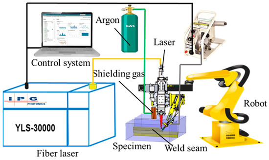
Figure 1.
Laser-wire-filling welding system.
The laser beam adopted a circular oscillation pattern with an oscillating frequency of 100 Hz, an amplitude of 2 mm, and a laser-wire distance of 2 mm. Other welding parameters are shown in Table 2. A single laser was used in backing welding, and a total of six layers were filled. The interlayer temperature was controlled within 150 °C. Ar was used as the shielding gas to protect the welded joint’s front and back during the welding process. The output pressure of the shielding gas Ar was 0.5 MPa.
Table 2.
Welding parameters.
After welding, the test plates were processed by a wire-cutting machine for sample preparation. Microstructure and phase distribution were observed and analyzed using an OLYMPUSGX71 optical microscope (Olympus Optical Co., Ltd., Japan), a JEM-2100F high resolution field emission transmission electron microscope (Keyence Corporation, Japan), an electron backscatter diffractometer (Bruker, Germany), an FEI Quanta-200 scanning electron microscope and D/MAX-rB X-ray diffractometer (FEI Inc., Portland, OR, USA). The harness test was conducted with an HVS-1000Z microhardness tester (Veiyee Co., Ltd., China). The tensile properties at room temperature were tested on an INSTRON 5569 electronic universal testing machine (Instron Inc., Boston, MA, USA).
3. Results and Discussion
Figure 2 shows the overall and cross-sectional macroscopic appearance of the Ti64 titanium alloy welded joint. No defects, such as porosity, cracks, edge bit, poor sidewall fusion, and welding deformation, were found. The WM of the welded joint is composed of coarse columnar grains, which grow along the temperature gradient increase direction. Columnar grains grow from both sides of the WM to the WM center. Under the optical microscope, the electric potential difference between the α phase and the β phase varies significantly. The β phase is easy to corrode and appears dark, while the α phase is difficult to corrode and appears bright. The width of the HAZ of the welded joint is relatively narrow, about 1 mm.
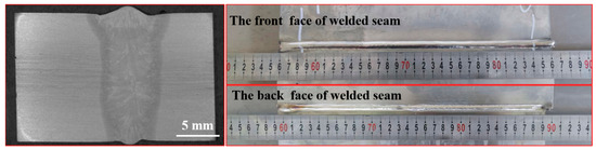
Figure 2.
Macroscopic appearance of welded joint.
Figure 3 is the microstructure morphology of the welded joint. It can be found that the largest grain microstructure appears in the WM. As their distance from the welded metal increases, the grains decrease gradually in dimension. Figure 3b–d are images of the microstructure of the WM under low and high magnification. From Figure 3b, a large number of columnar grains can be observed with an average width of 150 μm. From Figure 3c, we discover the eutectoid decomposition reaction of Ti-Fe is promoted by increasing the content of the Fe element in the flux-cored wire to 0.055 wt%. It can increase the probability of obtaining equiaxed grain microstructure and the contact area of the α’ martensite and incompletely transformed the β phase, then uplifting the area of heterophase boundaries, and finally realizing the optimization of the mechanical properties of the WM. It can be seen from Figure 3d that the interior of the coarse columnar grains is a basketweave microstructure interwoven by acicular α′ martensite. During the rapid cooling and solidification process of the molten pool, β phases have no time to diffuse and thus shear to form a supersaturated α′ martensite solid solution. The α′ martensite grows and nucleates inside the original β columnar grains, first forming one or several paralleled primary α′ martensite, which extend through the whole grain in the length direction until hitting the grain boundaries. Then, it forms a series of relatively fine secondary acicular α′ martensite, which stops growing at the grain boundaries or when hitting primary α′ martensite. It leads to the final basketweave morphology of the WM, which is full of acicular α’ martensite. Due to the addition of 0.5% β phase stable element Mo in the flux-cored welding wire, the resistance of lattice reorganization increases, and the required degree of supercooling increases, which leads to the decrease of the initial temperature of phase transition and the final formation of the acicular α’ martensite.
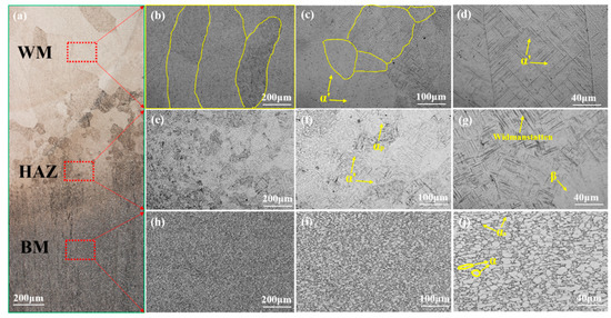
Figure 3.
Microstructure of welded joint: (a) overall micromorphology; (b–d) WM; (e–g) HAZ; (h–j) BM.
Figure 3e–g show the microstructure morphology images of the HAZ under both high and low magnification. The HAZ is composed of a few αp phases, Widmanstantten, the α’ martensite, and residual β phases. The acicular α’ martensite in this zone is fewer and finer than the WM. This is mostly because of the slow cooling rate of the metal in the HAZ during welding after being heated to a higher temperature. Moreover, due to the different distances of each part of the HAZ to the molten pool, the impact of the heat source on these parts is varied. As a result, grains near the fusion line are coarser than those far from the fusion line, and the acicular α’ martensite is more densely distributed. The microstructure near the fusion line is characterized by the intergrowth of columnar grains and equiaxed grains.
Figure 3h–j are the images of the microstructure in the BM under both high and low magnification. It could be observed that the BM presents bimodal morphology with interlaced equiaxed and elongated α phases and β phases. Meanwhile, a small amount of secondary αs phases can also be found in the β phase.
Figure 4a–c shows SEM images of the WM, HAZ, and BM of the welded joint. From these figures, it could be noted the WM is full of the α’ martensite with a few fine secondary α’ martensite in between. Finally, the WM presents basketweave morphology. The HAZ consists of a few primary αp phases, grain boundary αgb phase, Widmanstantten, and the secondary α’ martensite. It presents bimodal morphology with equiaxed and elongated α phases and a few granular β phases dispersedly distributed and interwoven with each other.
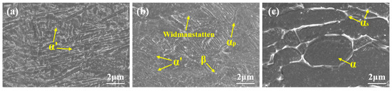
Figure 4.
Microstructure of welded joint SEM of (a) WM; (b) HAZ; (c) BM.
Figure 5 is the TEM morphology of the WM. It can be found that the WM microstructure is full of α’ martensite lath. Relatively dense dislocations could be observed in α’ martensite, as shown in Figure 5a. It is because when β phases shear to α’ martensite in the cooling process of the high temperature β phase zone, the burgers orientation relationship is followed, resulting in dislocation to coordinate the strain generated during phase transformation [19,20]. The average width of the α’ martensite lath is 0.60 μm. A small amount of incompletely transformed β phase is found interspersed between lath α’ martensite, as shown in Figure 5b. Studies by Zuo et al. [21] and Castany et al. [22] reveal dislocations always appear first at the phase boundaries. Hence, dislocation density at grain boundaries is significantly higher than that inside the phases. In Figure 5c, we can find dense dislocation walls at α’/β boundaries, which is related to the thermal expansion coefficient of α’ martensite and β phase. The thermal expansion coefficient of the former is much lower than that of the latter. Therefore, the greater thermal stress is inevitably concentrated at α’/β boundaries, leading to dense dislocation in corresponding areas. In Figure 5d, it is found that dislocation walls caused by a relatively denser dislocation block appear inside the α’ martensite.
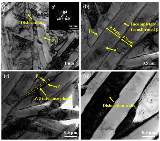
Figure 5.
TEM morphology of WM: (a) low magnification morphology of WM; (b) high magnification morphology; (c) α’/β interface phase; (d) dislocation walls.
According to the above analysis, the WM of titanium alloy is mainly composed of α’martensite and β phase structure. The distribution of titanium alloy elements in the welding process will further affect the microscopic characteristics, plastic deformation mode, and final mechanical properties of α’ and β phase structural units in the WM. Figure 6 is the alloying element distribution map obtained by EDS surface scanning and line scanning of the WM structure. According to the surface-scanning results, there is a large difference in the element concentration between the α’ martensite and the β phase, which is due to the dynamic redistribution of alloying elements with the shear of β→α’ martensite during the cooling process of the WM. The enrichment of Al in the α’ martensite and V in a small amount of the β phase resulted in a significant difference in α’/β element concentration.
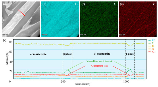
Figure 6.
Local EDS mapping of the Ti64 WM: (a) HAADF; (b) Al; (c) Ti; (d) V; (e) EDS line scanning along the red line in Figure 6a.
The content of Al in the α’ martensite is higher, and the content of V is lower, while the content of V is higher, and the content of Al is lower in the β phase. At the same time, it is found in Figure 6e that there should be a transition region at the phase boundary of the α’ martensite/β phase. According to the properties of alloy element and the pseudo-binary phase diagram of titanium alloy, the diffusion rate of the V element in the hcp structure is lower than that in the bcc structure, resulting in a higher content of V at the interface of the α’ martensite and the β phase. As a result, the content of the α’ martensitic stable element Al is lower in this area.
Figure 7 shows the grain morphology, orientation, and grain boundary angle distribution statistics in the WM. A continuous original β grain boundary was observed in the microstructure. Lei et al. [23] and Zafari et al. [24] also found the continuous grain boundary was the primary αp phase that nucleated and grew into a continuous grain boundary with sufficient time and nucleation driving force during the cooling process of the high-temperature β phase. Zhang et al. [25] showed inhibition of continuous grain boundary αgb phase generation could improve the ductility and toughness of titanium alloy. The microstructure of different orientations in the WM is interwoven and distributed. The anisotropic slats have a stronger ability to inhibit crack propagation than the anisotropic slats, which is beneficial for inhibiting crack propagation and improving the toughness of the material. At the same time, it can be found from Figure 7a that the acicular structure in the WM is smaller, and the length–diameter ratio is smaller. The green line in Figure 7b represents the small angle grain boundaries of 2~15°, and the black line represents the large angle grain boundaries of over 15°. The proportion of large angle grain boundaries in the WM is larger. The distribution of grain boundary orientation difference in the WM of the welded joint is shown in Figure 7c, and the distribution characteristics of peak values appear at the positions of 2°, 60°, and 90°. Among them, 60° and 90° are the two most common orientation difference angles after phase transformation in titanium alloy. The calculation results show the proportion of large angle grain boundary greater than 15° in the WM is about 84%, and the proportion between 55.5° and 66.5° is about 74%. According to the relevant literature [26,27], the impact toughness is closely related to the orientation difference distribution between grains. The orientation distribution between grains at a large angle can effectively prevent the propagation of microcracks in the intra-grain structure. In contrast, for the grain boundaries at a small angle, the crack can propagate from the next grain boundary only by deflecting a little angle. Therefore, the above test results imply the impact toughness of the WM of the welded joint will be better.
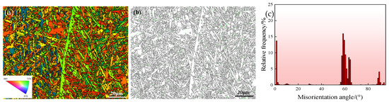
Figure 7.
EBSD orientation images of WM: (a) grain morphology; (b) grain orientation diagram; (c) misorientation angle distribution diagram.
The pole figure of the WM is shown in Figure 8. It could be perceived that for most grains, the angle between axis C and TD is 45°, and ⟨1120⟩ is parallel to the RD direction. The diffusion degree is high. The overall grain orientation is not clearly determinable, and the texture is not obvious. The inverse pole figure is shown in Figure 9. Microstructure shows {1210} grain orientation with obvious texture. Preferential orientation in the RD direction is weak. In the welding process of Ti64 titanium alloy, the high-temperature, single β phase structure was formed. In the cooling process, the β→α′ transformation took place. The crystal orientation of the transformed α′ martensite and original β phase meets burgers orientation relationship, which are {0001}α//{110}β and {1120}α//{111}β.
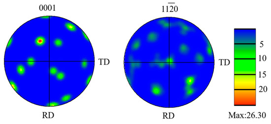
Figure 8.
Pole figures of WM.
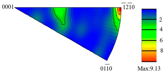
Figure 9.
Inverse pole figure of WM.
XRD was applied to determine the phase composition of the WM. The result is shown in Figure 10. The WM is mainly composed of an hcp crystal structure with no orthorhombic lattice structure observed. According to the lattice constant ratio c/a and the above microstructure analysis, it can be determined the as-welded WM is mainly composed of the α’ martensite with main strong peaks appearing, while 2θ = 40.5°. There are also a few weak multi-angle α phase diffraction peaks.
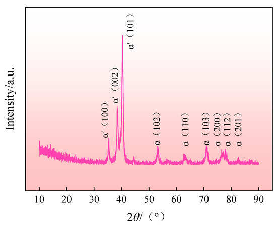
Figure 10.
XRD pattern of WM.
Figure 11 displays the microhardness distribution of the welded joint. Overall, the distribution sequencing is WM > HAZ > BM. The hardness distribution of the welded joint is closely related to the microstructure composition and phase content. Due to the high density of dislocation and twinning in α’ martensite [28], a considerable number of grain boundaries are generated. Therefore, its hardness is significantly higher than other phases. In the welded joint, the hardness of the WM with the most α’ martensite content is better than the HAZ and the BM. In the hardness loading process, the load causes dislocation slip to grain boundaries and thus leads to dislocation block. Grain boundaries have an obvious blocking effect on dislocation motion. With the increase of load, the density of the dislocation block rises as well, accompanied by the generation of stress concentration. When the concentrated stress is big enough to overcome the blocking effect of the grain boundaries, stress releases and produces plastic deformation, which leads to the dislocation motion of the adjacent grain microstructures, making the occurrence of the intersection of grain boundaries in adjacent grain microstructures to harden the material [29].
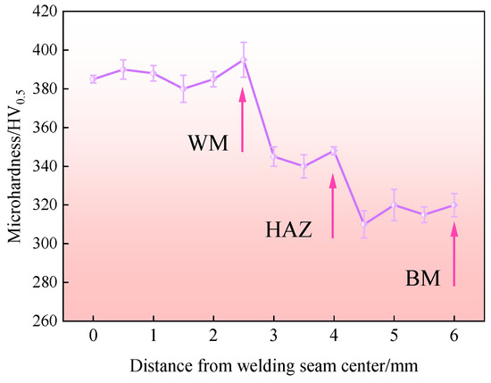
Figure 11.
Microhardness distribution of welded joint.
Table 3 shows the average test results of tensile properties at room temperature and impact properties of TC4 titanium alloy BM and four pieces of welded joints at room temperature. The tensile strength and elongation after fracture of the welded joint are similar to that of the BM, while the impact toughness at room temperature decreases slightly. Figure 12 shows the fracture side surface and tensile fracture location of the welded joint; the fracture location is located in the BM. The fracture surface is relatively flat, and the dimples are shallow and of different sizes, which are the typical features of ductile fracture. The smaller dimples are caused by the secondary αs [30].
Table 3.
Tensile and impact properties of titanium alloy BM and welded joint.
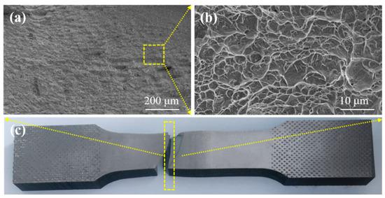
Figure 12.
Tensile fracture location and fracture-side surface of the welded joint: (a,b) fracture-side surface; (c) tensile fracture location.
Alloying element Mo belongs to β isomorphic stable element in TC4 titanium alloy, which can be infinitely miscible with titanium alloy and produce small lattice distortion. Therefore, adding alloying element Mo in laser-filling, flux-cored wire can improve the stability and strengthen the ability of the titanium alloy welded joint while maintaining the plasticity of the joint. In addition, adding Mo can reduce the phase transition temperature of laser-cored wire weld, which is conducive to the formation of the β phase in the WM [31], and the β phase can improve the plasticity and toughness of the WM. Therefore, adding Mo in the flux-cored wire has an obvious effect on improving the plasticity and toughness of titanium alloy laser-wire-filled welded joint.
Another reason for Mo’s strengthening effect on TC4 titanium alloy welded joint is that there are differences in atomic diameter, elastic modulus, and valence between Mo and Ti. Due to these differences, the addition of Mo can cause the change of total elastic energy, and the greater the change, the more obvious the strengthening effect. The difference between Mo = 6 and Ti = 4 is greater than that between V = 5 and Ti, as compared with Mo and V for β phase reinforcement elements. The difference between the elastic modulus of Mo and Ti is also significantly larger than the difference between V and Ti, which is 56,700 MPa. Therefore, the strengthening effect of Mo on the welded joint is obvious.
In the earlier stage, the research group used TC4 solid welding wire as the filler metal to perform laser-wire-filling welding of Ti64 titanium alloy with the same groove type [32]. Through comparison, it can be found that the self-developed flux-cored welding wire can obtain obvious optimization of WM microstructure and properties, especially the average elongation of welded joint after breaking, increased by about 15%.
Laser welding with filler wire has advantages, such as rapid heating and cooling. The heat input generated by the laser beam can melt part of the BM while melting the welding wire to form a liquid molten pool. Under the rapid cooling rate after welding and driven by epitaxial growth, the nucleating grains perpendicular to the edge of the molten pool grow into symmetrical coarse columnar microstructures along the direction opposite the cooling orientation [33]. When the liquid metal cools from high temperature to phase transformation starting temperature, the rapid cooling rate prevents the β phase from atomic diffusion to form the α equilibrium phase, and the β phase atoms can only change lattice composition via short-range-ordered transition [34]. Hence, the supersaturated solid solution α′ phase, namely, the acicular martensite microstructure, is formed in the WM. Meanwhile, the size of the columnar β grains limits the length of the α′ martensite structure formed by the shear mode. The acicular α′ martensite constitutes a basketweave microstructure. The evolution of microstructure in the WM is shown in Figure 13a–d.
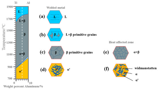
Figure 13.
Microstructure evolution of Ti64 titanium alloy welded joint: WM: (a) L; (b) L + β; (c) β; (d) α′; HAZ: (e) α + β; (f) α + widmanstatten + α′.
Figure 13e,f shows the microstructure evolution of the HAZ. During welding, the heat input from the molten pool to the HAZ is seriously reduced, and the temperature is therefore not high enough to melt the BM of titanium alloy. That is, the highest temperature of the HAZ fails to trigger the transformation from the α phase to the β phase. Instead, a few relatively large α phases are forced to devour the surrounding fine α phases to form massive α colonies. At a lower cooling rate, the Widmanstatten structure remains, and the residual β phase can be transformed into the acicular α′ martensite dispersed along αgb.
4. Conclusions
(1) No defects, such as porosity, cracks, edge biting, poor sidewall fusion, and welding deformation, were found in the titanium alloy welded joint. The WM of the welded joint is mostly composed of the acicular α’ martensite, a small amount of residual β phases, and a small amount of equiaxed grain structure, which can effectively increase the interface area of the dissimilar phase. The final WM shows a “netted basket” morphology. The width of the HAZ is narrow, about 1 mm, mainly composed of a small primary αp phase, the Widmanstatten phase, and a small amount of residual β phases. Meanwhile, the microstructure near the fusion line is columnar and equiaxed.
(2) The average width of the α’ martensite lath is about 0.60 μm, and there are a few incomplete β phases between the lath α’ martensite, and the dense dislocation wall is formed at the α’/β boundary at the same time. Al and V are enriched in the α’ martensite and β phases. At the same time, there is a transition region at the boundary of the α’ martensite/β phase, and V is aggregated at the interface of the α’ martensite/β phase, while Al is less in this region.
(3) The grain boundary orientation difference in the WM peaks at 2°, 60°, and 90°, and the proportion of large grain boundaries with orientation difference greater than 15° is about 84%, and the proportion between 55.5° and 66.5° is about 74%. The XRD test also confirms the WM is mainly composed of the α’ martensite, and there are a few very weak multi-angle α phase diffraction peaks, and the main strong peak appears at 2θ = 40.5°.
(4) The overall microhardness distribution of the welded joint is generally in the order of WM > HAZ > BM. When the welded joint breaks at the BM position, the tensile strength and elongation after fracture of the welded joint are similar to that of the BM, and the impact toughness of the welded joint at room temperature is slightly lower than that of the BM, which ensures the balance between strength plasticity and toughness of the welded joint.
(5) In the process of laser-wire-filling welding, the size of the columnar β grain in the WM restricts the length of the α’ martensite formed by shear mode so the fine acicular α’ martensite with cross-distribution finally forms basket texture. The maximum temperature in the HAZ does not transform the α to β phase but forces a small amount of the larger α phase to engulf the smaller surrounding α phase, forming a large number of α colonies. At lower cooling rates, Widmanstatten structures remain, and the residual β phase can be transformed into fine acicular α’ martensite dispersed along αgb.
(6) The Fe element in the flux-cored wire can effectively promote the eutectoid decomposition of Ti-Fe to improve the probability of equiaxed grain structure, increase the contact area between the α’ martensite and the incomplete β phase, and then increase the area of the heterogeneous interface. The addition of 0.5% β phase stable element Mo in the flux-cored welding wire increases the resistance of lattice reorganization and the required degree of supercooling, which leads to the decrease of the initial temperature of phase transition and the formation of acicular α’ martensite, which can finally realize the optimization of the mechanical properties of the welded metal.
Author Contributions
Conceptualization, M.W., N.F. and L.S.; validation, P.W., R.H. and K.X.; formal analysis, X.W., J.Q. and Z.Z.; investigation, S.L.; resources and methodology, J.S.; supervision, W.L. All authors have read and agreed to the published version of the manuscript.
Funding
The work was supported by the National Key Research and Development Plan of China (No. 2021YFB3401100); Heilongjiang Head Goose Action Plan Advanced Welding Technology Innovation Team of Energy Equipment (No. 201916120) and Program of Open Project of the State Key Laboratory of New Brazing Materials and Technology (No. SKLABFMT202005).
Data Availability Statement
The data presented in this study are available on request from the corresponding author.
Conflicts of Interest
The authors declare no conflict of interest.
References
- Long, W.; Zhang, G.; Zhang, Q. In situ synthesis of high strength Ag brazing filler metals during induction brazing process. Scr. Mater 2016, 110, 41–43. [Google Scholar] [CrossRef]
- Liu, T.; Zhang, S.; Wang, Q.; Min, X.; Dong, C. Composition formulas of Ti alloys derived by interpreting Ti-6Al-4V. Sci. China Technol. Sci. 2021, 64, 1732–1740. [Google Scholar] [CrossRef]
- Jia, C.L.; Wu, L.H.; Xue, P.; Zhang, H.; Ni, D.R.; Xiao, B.L.; Ma, Z.Y. Static spheroidization and its effect on superplasticity of fine lamellae in nugget of a friction stir welded Ti-6Al-4V joint. J. Mater. Sci. Technol. 2022, 119, 1–10. [Google Scholar] [CrossRef]
- Yang, T.; Xu, D.; Chen, W.; Yang, R.; Lv, S. Microstructure evolution and deformation resistance of heavy-thickness Ti-6Al-4V narrow-gap welded joints. Mater. Lett. 2019, 250, 116–118. [Google Scholar] [CrossRef]
- Xu, P.Q.; Li, L.; Zhang, C.S. Microstructure characterization of laser welded Ti-6Al-4V fusion zones. Mater. Charact. 2014, 87, 179–185. [Google Scholar] [CrossRef]
- Long, J.; Zhang, L.J.; Zhang, L.L.; Ning, J.; Zhuang, M.X.; Zhang, J.X.; Na, S.J. Analysis of heterogeneity of fatigue properties of double-sided electron beam welded 140 mm thick TC4 titanium alloy joints. Int. J. Fatigue 2021, 142, 105942. [Google Scholar] [CrossRef]
- Brandizzi, M.; Satriano, A.A.; Sorgente, D.; Tricarico, L. Laser-arc hybrid welding of Ti6Al4V titanium alloy: Mechanical characterization of joints and gap tolerance. Weld. Int. 2013, 27, 113–120. [Google Scholar] [CrossRef]
- Sun, G.; Wang, Z.; Lu, Y.; Chen, M.; Yang, K.; Ni, Z. Under water laser welding/cladding for high-performance repair of marine metal materials: A review. Chin. J. Mech. Eng. 2022, 35, 42–60. [Google Scholar] [CrossRef]
- Voisin, T.; Calta, N.P.; Khairallah, S.A.; Forien, J.B.; Balogh, L.; Cunningham, R.W.; Rollett, A.D.; Wang, Y.M. Defects-dictated tensile properties of selective laser melted Ti-6Al-4V. Mater. Des. 2018, 158, 113–126. [Google Scholar] [CrossRef]
- Fang, N.; Guo, E.; Huang, R.; Yin, L.; Chen, Y.; Zeng, C.; Cao, H.; Zou, J.; Xu, K. Effect of welding heat input on microstructure and properties of TC4 titanium alloy ultra-narrow gap welded joint by laser welding with filler wire. Mater. Res. Express 2021, 8, 016511. [Google Scholar] [CrossRef]
- Sun, W.; Wang, S.; Wu, M.; Hong, M.; Chen, Y.; Xin, J.; Zhang, P.; Qin, Y.; Fang, N. Revealing tensile behaviors and fracture mechanism of Ti-6Al-4V titanium alloy electron-beam-welded joints using microstructure evolution and in situ tension observation. Mat. Sci. Eng. A 2021, 824, 141811. [Google Scholar] [CrossRef]
- Huang, Z.; Cai, Y.; Mu, W.; Li, Y.; Hua, X. Effects of laser energy allocation on weld formation of 9% Ni steel made by narrow gap laser welding filled with nickel based alloy. J. Laser. Appl. 2018, 30, 032013. [Google Scholar] [CrossRef]
- Kawahito, Y.; Mizutani, M.; Katayama, S. High Quality welding of stainless steel with 10 kW high power fibre laser. Sci. Technol. Weld. Joi. 2009, 14, 288–294. [Google Scholar] [CrossRef]
- Yamazaki, Y.; Abe, Y.; Hioki, Y.; Nakatani, M.; Kitagawa, A.; Nakata, K. Fundamental study of narrow-gap welding with oscillation laser beam. Weld. Int. 2016, 30, 699–707. [Google Scholar] [CrossRef]
- Zhang, C.; Bao, X.; Hao, M.; Chen, W.; Zhang, D.; Wang, D.; Zhang, J.; Liu, G.; Sun, J. Hierarchical nano-martensite-engineered a low-cost ultra-strong and ductile titanium alloy. Nat. Commun. 2022, 13, 5966. [Google Scholar] [CrossRef]
- Chen, Y.; Feng, J.; Li, L.; Chang, S.; Ma, G. Microstructure and mechanical properties of a thick-section high-strength steel welded joint by novel double-sided hybrid fibre laser-arc welding. Mat. Sci. Eng. A-Struct. 2013, 582, 284–293. [Google Scholar] [CrossRef]
- Jia, C.L.; Wu, L.H.; Xue, P.; Ni, D.R.; Xiao, B.L.; Ma, Z.Y. Effect of static annealing on superplastic behavior of a friction stir welded Ti-6Al-4V alloy joint and microstructural evolution during deformation. J. Mater. Sci. Technol. 2022, 130, 112–123. [Google Scholar] [CrossRef]
- Yuan, D.; Shao, S.; Guo, C.; Jiang, F.; Wang, J. Grain refining of Ti-6Al-4V alloy fabricated by laser and wire additive manufacturing assistedwith ultrasonic vibration. Ultrason. Sonochem. 2021, 73, 105472. [Google Scholar] [CrossRef] [PubMed]
- Meng, L.; Kitashima, T.; Tsuchiyama, T.; Watanabe, M. Effect of α precipitation on β texture evolution during β-processed forging in a near-β titanium alloy. Mat. Sci. Eng. A 2020, 771, 138640. [Google Scholar] [CrossRef]
- Sun, Z.; Chen, G.; Fu, X.; Wang, Y.; Hou, H.; Zhou, W. TEM investigations on hydrogen induced phase transformation in Ti-6Al-4V alloys. Acta Metall. Sin.-Engl. 2010, 23, 357–362. [Google Scholar]
- Zuo, J.H.; Wang, Z.G.; Han, E.H. Effect of microstructure on ultra-high cycle fatigue behavior of Ti-6Al-4V. Mat. Sci. Eng. A 2008, 473, 147–152. [Google Scholar] [CrossRef]
- Castany, P.; Pettinari-Sturmel, F.; Crestou, J.; Douin, J.; Coujou, A. Experimental study of dislocation mobility in a Ti-6Al-4V Alloy. Acta Mater. 2007, 55, 6284–6291. [Google Scholar] [CrossRef]
- Lei, L.; Zhao, Q.; Wu, C.; Zhao, Y.; Huang, S.; Jia, W.; Zeng, W. Variant selection, coarsening behavior of α phase and associated tensile properties in an α+β titanium alloy. J. Mater. Sci. Technol. 2022, 99, 101–113. [Google Scholar] [CrossRef]
- Zafari, A.; Lui, E.W.C.; Li, M.; Xia, K. Enhancing work hardening and ductility in additively manufactured β Ti: Roles played by grain orientation, morphology and substructure. J. Mater. Sci. Technol. 2022, 105, 131–141. [Google Scholar] [CrossRef]
- Zhang, L.G.; Tang, J.L.; Wang, Z.Y.; Zhou, J.Y.; Wu, D.; Liu, L.B.; Masset, P.J. Pseudo-spinodal mechanism approach to designing a near-β high-strength titanium alloy through high-throughput technique. Rare Met. 2021, 40, 2099–2108. [Google Scholar] [CrossRef]
- Pan, X.; He, W.; Cai, Z.; Wang, X.; Liu, P.; Luo, S.; Zhou, L. Investigations on femtosecond laser-induced surface modification and periodic micropatterning with anti-friction properties on Ti6Al4V titanium alloy. Chin. J. Aeronaut. 2022, 35, 521–537. [Google Scholar] [CrossRef]
- Quazi, M.M.; Fazal, M.A.; Haseeb, A.S.M.A.; Yusof, F.; Masjuki, H.H.; Arslan, A. Effect of rare earth elements and their oxides on tribo-mechanical performance of laser claddings: A review. J. Rare Earth. 2016, 34, 549–564. [Google Scholar] [CrossRef]
- Kim, J.H.; Semiatin, S.L.; Lee, Y.H.; Lee, C.S. A self-consistent approach for modeling the flow behavior of the alpha and beta phases in Ti-6Al-4V. Metall. Mater. Trans. A 2011, 42, 1805–1814. [Google Scholar] [CrossRef]
- Prashanth, K.G.; Damodaram, R.; Maity, T.; Wang, P.; Eckert, J. Friction welding of selective laser melted Ti6Al4V parts. Mat. Sci. Eng. A 2017, 704, 66–71. [Google Scholar] [CrossRef]
- Ito, Y.; Murakami, S.; Tsuji, N. SEM/EBSD analysis on globularization behavior of lamellar microstructure in Ti-6Al-4V during hot deformation and annealing. Metall. Mater. Trans. A 2017, 48, 4237–4246. [Google Scholar] [CrossRef]
- Fang, N.; Guo, E.; Xu, K.; Huang, R.; Ma, Y.; Chen, Y.; Yang, Y.; Xie, J. Observation of grain growth and phase transformation in weld zone of Ti-6Al-4V titanium alloy by laser welding with filler wire. Mater. Res. Express 2021, 8, 056507. [Google Scholar] [CrossRef]
- Fang, N.; Guo, E.; Xu, K.; Huang, R.; Ma, Y.; Zeng, C.; Yang, Y.; Xie, J.; Cao, H. Effect of shielding gas on microstructures and mechanical properties of TC4 titanium alloy ultranarrow gap welded joint by laser welding with filler wire. Adv. Mater. Sci. Eng. 2021, 2021, 9582421. [Google Scholar] [CrossRef]
- Köse, C.; Karacam, E. Robotic Nd: YAG fiber laser welding of Ti-6Al-4V alloy. Metals 2017, 7, 221. [Google Scholar] [CrossRef]
- Köse, C.; Karaca, E. Effect of pre and post weld heat treatments on the microstructure and mechanical properties of fiber optic beam delivery system assisted robotic Nd: Yaglaser welded Ti-6Al-4V Alloy. Arch. Metall. Mater. 2018, 63, 1225–1233. [Google Scholar]


Disclaimer/Publisher’s Note: The statements, opinions and data contained in all publications are solely those of the individual author(s) and contributor(s) and not of MDPI and/or the editor(s). MDPI and/or the editor(s) disclaim responsibility for any injury to people or property resulting from any ideas, methods, instructions or products referred to in the content. |
© 2023 by the authors. Licensee MDPI, Basel, Switzerland. This article is an open access article distributed under the terms and conditions of the Creative Commons Attribution (CC BY) license (https://creativecommons.org/licenses/by/4.0/).