Abstract
Compound casting is a process in which a single component is made from two metallic materials, such as aluminum and steel. Solid-liquid bimetallic compounds can be produced by suitable process control. This technology can reduce the number of joining processes, and the specific properties of the respective metal component can be used for specifically designed product properties, for example, where lightweight and high strength are needed. This paper presents an experimental methodology for producing a purely material-bonded bimetallic joint from cast aluminum and zinc-coated sheet steel in 3D sand casting using an inductive heating system. The process-related temperature characterisation in the compound zone is described using a heating test rig and temperature measurements. It shows that inductive preheating can only produce a material bond between the aluminum casting and the coated steel sheet. Shear tensile tests showed strengths between 15 MPa and 22 MPa. Laser surface pre-treatment using laser ablation cutting on the coated steel sheet was carried out to investigate the benefit of possible microform-locking. The results show a strength-reducing influence on the tensile shear tests. Micrographs showed the formation of Al4.5FeSi and Al7Fe2Si, as well as the formation of other undefined intermetallic phases. The thickness of the compound zone is 10 µm.
1. Introduction
By combining different materials within a component, the individual material properties can be used in a targeted manner. Today, joining processes such as welding or glueing are used. With compound casting technology, the number of process steps can be reduced, as the joining operations can be integrated directly into the process [1]. Due to the increasing trend of multi-material design (MMD) in the automotive industry [2], combining two different materials, like cast aluminum and sheet steel, is particularly interesting for lightweight design.
Dezellus et al. displayed that oxide layers act as wetting barriers and inhibit the formation of a metallurgical bond [3]. Therefore coatings are essential to create a defect-free continuous metallurgical bond [4]. Various studies on producing aluminum/steel bimetals through compound casting have been performed in recent years. The main focus of these studies was to improve metallurgical bonding through coatings: [5,6,7,8,9,10].
Bakke et al. [5] investigated the compound casting process using zinc-coated steel pipes (ST37) and the casting alloy AlSi7Mg0.3. The phases Al4.5FeSi (β) and Al4Fe1.7Si were detected. The zinc layer dissolved entirely upon the impact of the Al melt. As ZnFe phases were formed during the piece galvanising process, the local Fe content of the melt increased. The absence of the Al5Fe2 and the Al3Fe phase is attributed to insufficient time at elevated temperatures. The morphology of the β-phase has, according to Bakke et al., a significant influence on the mechanical properties. The sharp-edged phase boundaries lead to local stress peaks and promote crack initiation.
Within the scope of further investigations, Bakke et al. [6] produced a material bond without preheating the inserts using a structural steel piece (S235JR) as the insert material. However, these were steel pipes onto which the casting material was shrunk. Consequently, the bonding improved significantly, and intermetallic phases could form.
In another study, Bakke et al. used tin-coated steel tubes (S235JR) and AlSi7Mg0.3 as casting material. The phases Al5Fe2 (η), Al4Fe1.7Si, Al7.4Fe2Si (α) and Al4.5FeSi were detected starting from the steel to the cast material. The average thickness of the compound zone was 12 µm. As with the zinc coating, the tin layer was completely dissolved in the melt. The different phases in the BSE images (backscattered electrons) can be clearly seen from their contrasts. A peritectic reaction possibly formed the α-phase during the cooling process [7].
The investigation by Shin et al. focused on the influence of previous sandblasting treatment of the steel inserts. Nevertheless, the results of the zinc-coated inserts that were not sandblasted can be used as a reference. Shin et al. found the Al13Fe4, Al8Fe2Si and β phases and suggested that the latter phases originated from peritectic reactions. They see why the η-phase was not detectable in the compound zone, mainly in the short time at strongly elevated temperatures and the high silicon content. In particular, it is assumed that the η-phase in other publications in which it was detected could already have been formed during the coating process and is, therefore, not a product of the compound casting process [8].
Z. Bao et al. investigated aluminum/steel compound formation using electroless nickel and a heat preservation device at a temperature of 760 °C. Good metallurgical bonding is formed between liquid aluminum (ZL102) and nickel-plated heat resistant steel utilizing diffusion, forming an intermediate layer. The phase composition of the intermediate layer is, according to the authors, mainly α-Al, α-Fe, Al5Fe2, Al5FeSi and Al8Fe2Si, but the contents of Al5Fe2, Al8Fe2Si and Al5FeSi are quite small. The phase composition near the aluminum side is Al8Fe2Si, while the phase composition near the nickel-plated steel side is Al5Fe2 [9].
Fang et al. used an AlSi coating for steel/Al compound casting. This led to a failure with ductile fraction, but the shear tensile strength was only 7.7 MPa due to incomplete bonding [10].
However, creating metallic continuity requires several measures that must be considered in compound casting. These include the preheating of the insert, the provision of a protective gas atmosphere and the use of coated inserts. This work investigates a new method to produce hybrid components from cast aluminum and sheet steel in a 3D sand casting process using an inductive heating system and how different process parameters affect the mechanical properties and microstructure of the joints.
The casting material used is AlSi7Mg0.3, the sheet steel used is HC340LA without coating, and HX340LAD+Z100MBO with a zinc coating (7 µm) is used as insert material. The surface of some coated samples underwent laser surface ablation cutting to investigate the potential for improving the compound bonding by enhancing the surface area and creating microform-locking. The steel sheet is integrated into a vertically divided 3D-printed sand mould. An inductive heating system is implemented into the sand mould in the area of the compound zone. Parallel to the heating process of the sheet, the liquid aluminum is poured into the sand mould. Shear tensile test samples are produced and investigated through shear tensile testing and microstructural investigations.
2. Materials and Methods
2.1. Materials
The steel sheet used for the castings trials, laser surface pre-treatment, shear testing and microscopic investigations was a band hot-dip zinc-coated microalloyed steel of the type HX340LAD+Z100 with a zinc layer thickness of 7 µm. The same steel type without zinc coating was used for tensile testing of type E samples, according to DIN 50125. Due to the number of tests and the different configurations, an uncoated DC04 steel sheet was used to measure the heating behaviour. The material has the same industrial relevance and sheet surface quality. The dimensions of the sheets were 100 × 30 × 1.5 mm. On the casting side, an AlSi7Mg0.3 alloy was used with and without adding any melt refining agents. The melt refining agents are AlSr10 and AlTi5B1. 3D-printed furan resin-based sand moulds were used as casting moulds. In addition, argon gas type 5.0 was used for flushing the mould during the inductive sheet heating process in the casting test to protect the steel sheet from oxidation before pouring the molten aluminum.
2.2. Measurement of the Heating Behaviour of Induction-Heated Steel Sheet Samples
In order to investigate heating temperature in the compound zone through inductive heating dependence of power and time, a temperature test set-up was built as seen in Figure 1.
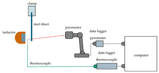
Figure 1.
Schematic Illustration of the Temperature Test Rig.
For the temperature measurement, a type K thermocouple was welded to the DC04 sheets without coating in the centre of the compound zone. The size of the compound zone is 30 × 20 mm. The sheet was previously degreased with isopropanol. The sheet was fixed in a clamp. An induction unit (Powerduction 160 LG, inductor type L90, GYS GmbH, Aachen, Germany) was positioned to the left of the steel sheet to heat it. The distance between the inductor and the sheet metal was 7 mm. An infrared pyrometer (CT-SF22-C3, Micro-Epsilon Messtechnik GmbH & Co. KG, Ortenburg, Germany) on the right side of the steel sheet was used for comparative measurements, as it is possible that inductive coupling could affect the thermocouple measurement. Based on literature values [11] and pretesting, the emission coefficient was determined to be ε = 0.62. The distance between the pyrometer and steel sheet was 200 mm. The thermocouple and pyrometer were connected to a computer for data collection. Heating tests were carried out with 50/60/70/80/90 and 100% inductor power and a heating duration of 15 s. The total heating capacity of the inductor is 16 kW, selectable in 1500 W steps. The recorded temperature curves from the thermocouple and the pyrometer were evaluated and compared in a temperature-time diagram. In addition, video recordings were made using a digital camera for qualitative pictorial evaluation of the heating behaviour to document the heat profile distribution in the sheet metal. The temperature measurement results should provide orientation about the existing substrate temperature in the compound casting. The quantitative results are used to determine the start of the casting time.
2.3. Tensile Testing of Inductive Heated Steel Sheets
In order to determine the influence of induction heating on the mechanical properties of the steel sheet, flat tensile specimens were milled out of the steel sheets after induction heating at an induction power of 50/60/70/80 and 90% and a heating time of 15 s. In addition, reference samples were tested without inductive heating. 4 samples were tested per parameter set according to DIN 50125. The mechanical properties are measured using a universal testing machine (ZT150, ZwickRoell GmbH & Co. KG, Ulm, Germany). The tensile strength Rm in MPa, uniform elongation in Ag in %, and the elongation at fracture A in % with a test speed of 1 mm/min at room temperature has been measured.
2.4. Laser Engraving of Steel Sheet at the Compound Zone
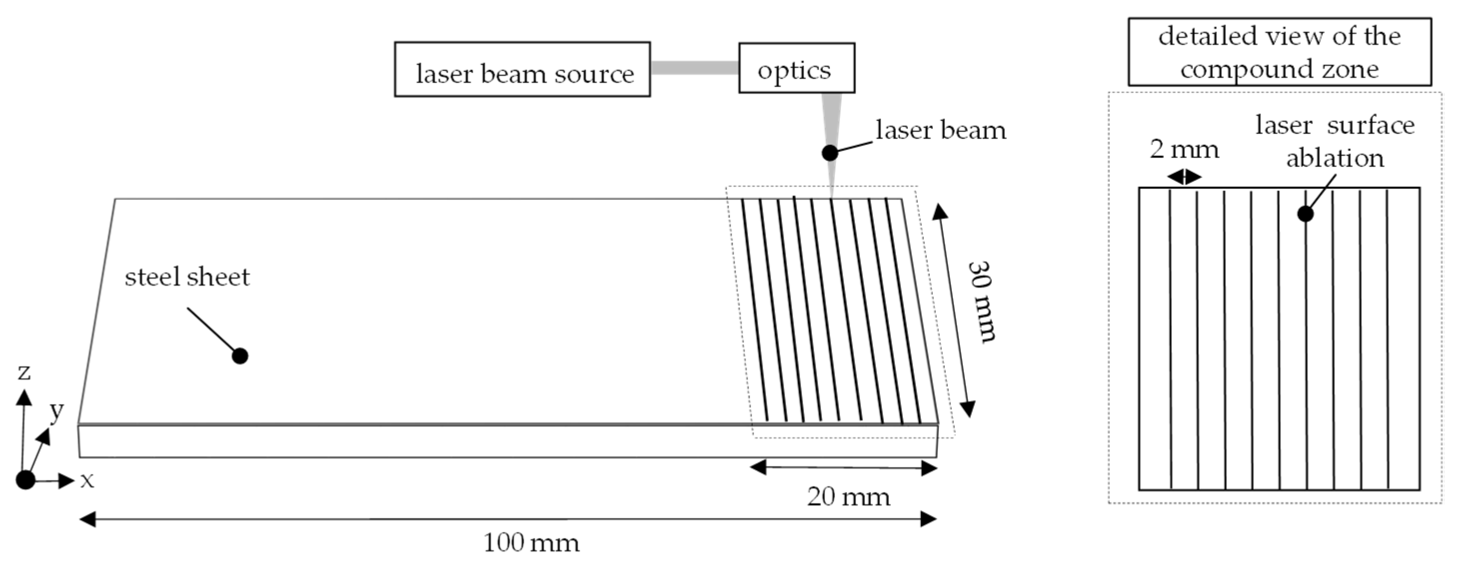
The laser structuring process was performed using a single-mode Ytterbium fiber laser (YLR 3000 SM, IPG Laser GmbH, Burbach, Germany) with a maximum output power of 3 kW and a wavelength of 1064 nm. A scanning optic (AS-Fiber 30, RAYLASE GmbH, Wessling, Germany) was utilized for the beam positioning, resulting in a focal diameter of 50 µm on the surface of HX340LAD+Z100 steel sheets. Nine unidirectional lines were placed on each specimen at a distance of 2 mm apart. All cutting kerfs were created with a laser power of 3 kW, a scanning speed of 7 m/s and with a double exposure. A crossjet was utilized to remove process by-products from the process zone. The goal of the laser structuring was to increase the shear tensile strength of the compound cast specimens through microform-locking and increased surface area. Three samples were prepared for the casting trials and the process is depicted in Figure 2.
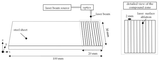
Figure 2.
Illustration of Laser-based Surface Structuring of HX340LAD+Z100 Sheet Steel.
2.5. Casting Trials
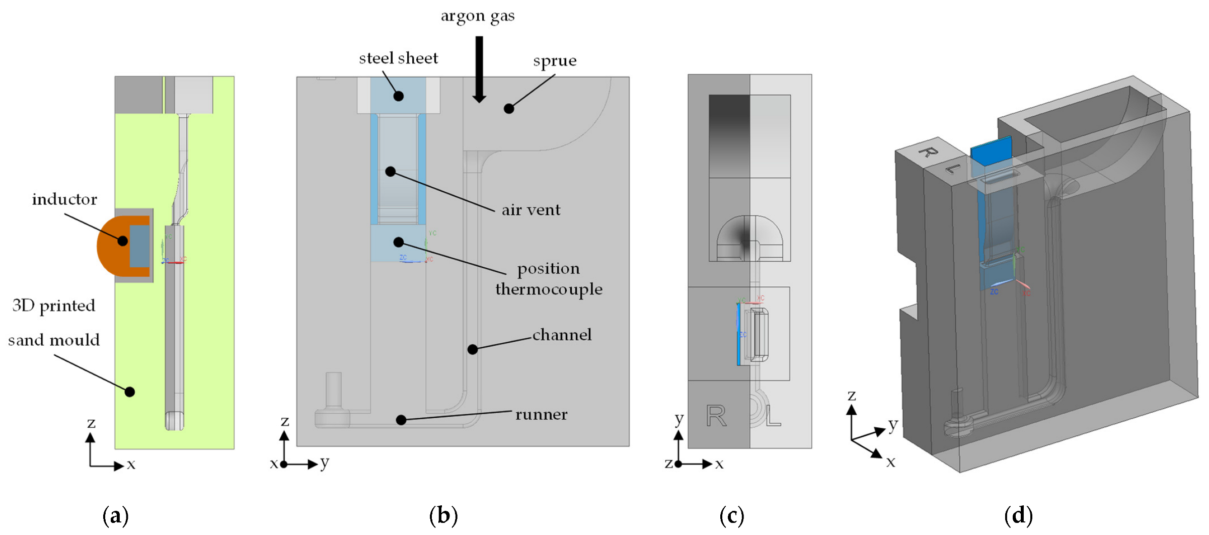
A steel sheet specimen was placed in a vertically divided 3D sand casting mould and firmly clamped together with the other mould half. Similar to the temperature test bench, the inductor was integrated into the mould near the compound zone at a distance of 7 mm from the sheet. The molten aluminum was prepared in a resistance-heated crucible furnace. The melt was not degassed but treated with and without finishing agents. Finishing agents are AlSr10, with a target content of 200 to 300 ppm, and AlTi5B1, with a target content of 0.16 wt-%, in the melt. The mould was flushed with argon during the heating process until the molten aluminum was poured in. The casting process is carried out after 6 s of induction heating. Casting tests are carried out at 720 °C ± 5 °C casting temperature with 50% and 70% induction power and 760 °C ± 5 °C casting temperature with 50% and 70% induction power. The total heating capacity of the inductor is 16 kW, selectable in 1500 W steps (Powerduction 160 LG, inductor type L90, GYS GmbH, Aachen, Germany). The temperature of the melt was checked using a thermocouple before casting. In the compound zone, the incoming melt temperature on the aluminum side was measured using an integrated thermocouple in the mould. The tip of the thermocouple in the mould had a distance of approximately 5 mm from the steel sheet. HX340LAD+Z100 steel sheets with and without laser processing are used for the casting trials. Figure 3 shows the setup for the casting trials schematically.
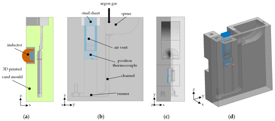
Figure 3.
(a) Cut View and Inductor Position. (b) Casting System. (c) Top View. (d) Overall View.
2.6. Sampling for Further Examination
Figure 4a shows the sample area schematically after the manufacturing process and Figure 4b the sample dimensions and further metallographic preparation. The blue marking represents the steel sheet side, and the grey marking represents the casting side of the shear tensile specimen. In the case of material bonding, the specimen is separated from the casting system. Whether or not a material bond was formed can be seen after unpacking the specimen from the casting mould since both partners can only be held together by a pure material bond due to the geometry of the specimen. The compound zone overlap was 20 mm. After sampling, the specimen undergoes shear tensile testing or is prepared for microstructure analysis.
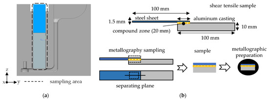
Figure 4.
(a) Sampling Area of the Casting. (b) Dimensions of Shear Tensile Specimen and Metallographic Preparation.
2.7. Shear Tensile Testing
In order to investigate the bonding strength of the aluminum/steel shear tensile specimens in dependence on the casting parameters and laser treatment, shear tensile tests are carried out with a universal testing machine, according to DIN EN 1465 using a universal testing machine (ZT150, ZwickRoell GmbH & Co. KG, Ulm, Germany). For each set of parameters, three samples were tested. For the laser-pre-treated samples, two of three samples were investigated. The clamping length on the sheet and casting side was 30 mm. A pre-load between 100 N is applied for clamping the specimen. The test speed was 1 mm/min at room temperature. It is ensured that the clamping length was the same on the cast and the sheet side and that the bond zone was perpendicular to the tensile axis through adjustable clamps. The following formula determined the shear tensile strength from the maximum tensile force Fmax.
τ is the shear tensile strength in MPa, Fmax the maximum force till fracture in N, l the length of the test surface of the shear tensile specimen in mm and w the width of the test area of the shear tensile specimen in mm.
2.8. Microstructural Imaging
The compound casting samples are embedded and then ground and polished. The flat tensile specimens are additionally subjected to etching with Nital 3% to analyse the influence of induction heating on the microstructural changes. Light microscopic images are taken. In addition, the compound casting samples are analyzed using SEM with a BSE-EDX detector and 15 kV acceleration voltage to determine the composition of the intermetallic phases.
3. Results
3.1. Heating Behaviour of Induction-Heated Steel Sheets
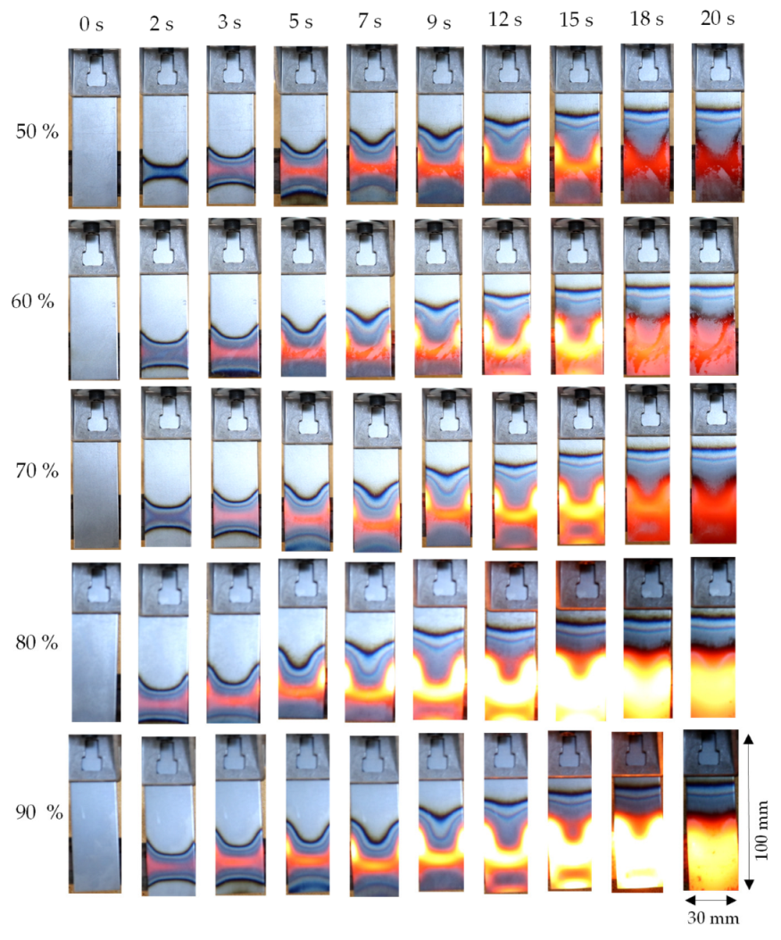
Figure 5 shows the heating behaviour of induction-heated DC04 steel sheets qualitatively without coating as a function of power in %. The images show that the radiation behaviour of the sheets changes as a function of the inductor power. The higher the power, the greater the radiation intensity and, thus, the temperature in the sheet. However, this does not apply equally to all power levels. Between 60 and 70%, the visual comparison shows a very similar heat profile. At 80%, there is a higher heat distribution compared to 90% at 5 to 15 s. The non-linear behaviour is also presented in the temperature measurements in Figure 5, Figure 6 and Figure 7. Furthermore, it can be seen that the I-shaped heat profile in the sheet spreads faster with increasing power—the I-profile results from the inductor positioning on the sheet and the inductor shape.
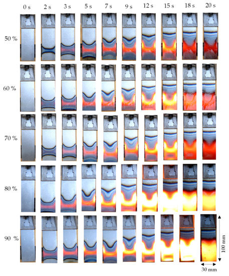
Figure 5.
Qualitative Heating Behaviour of Induction-Heated Steel Sheets without Coating.
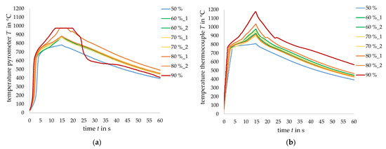
Figure 6.
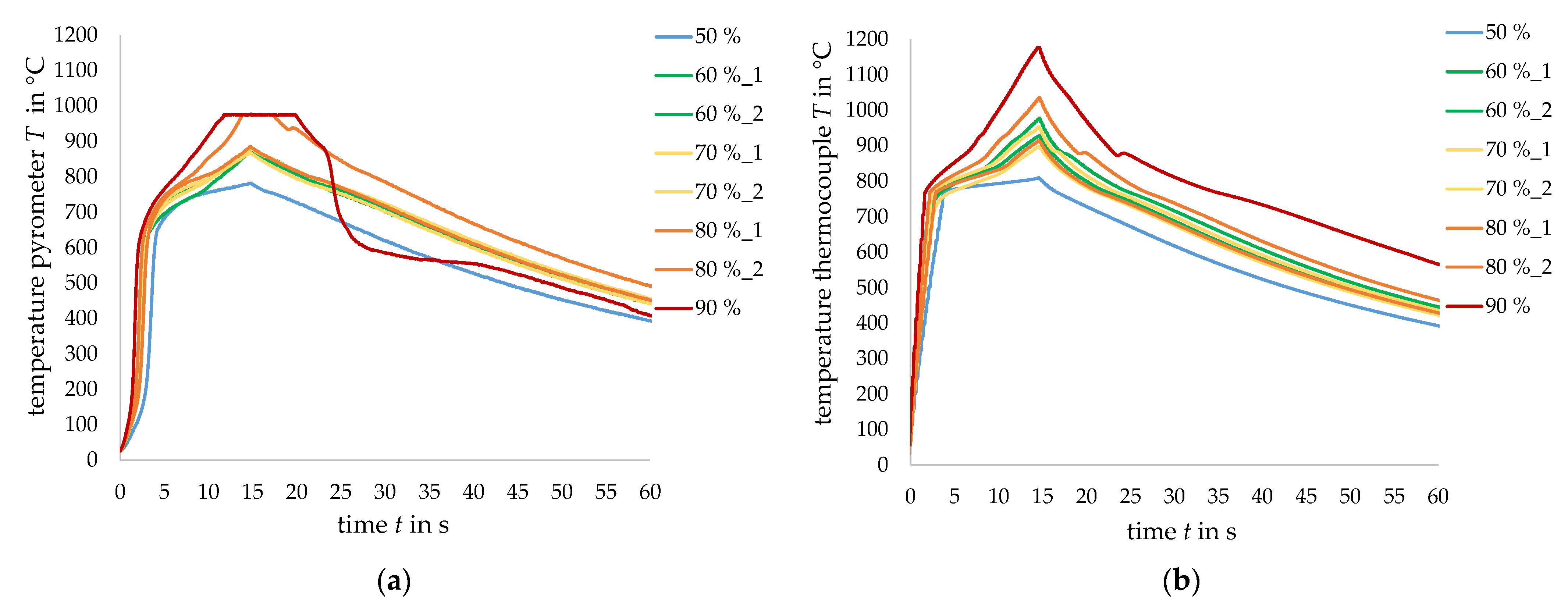
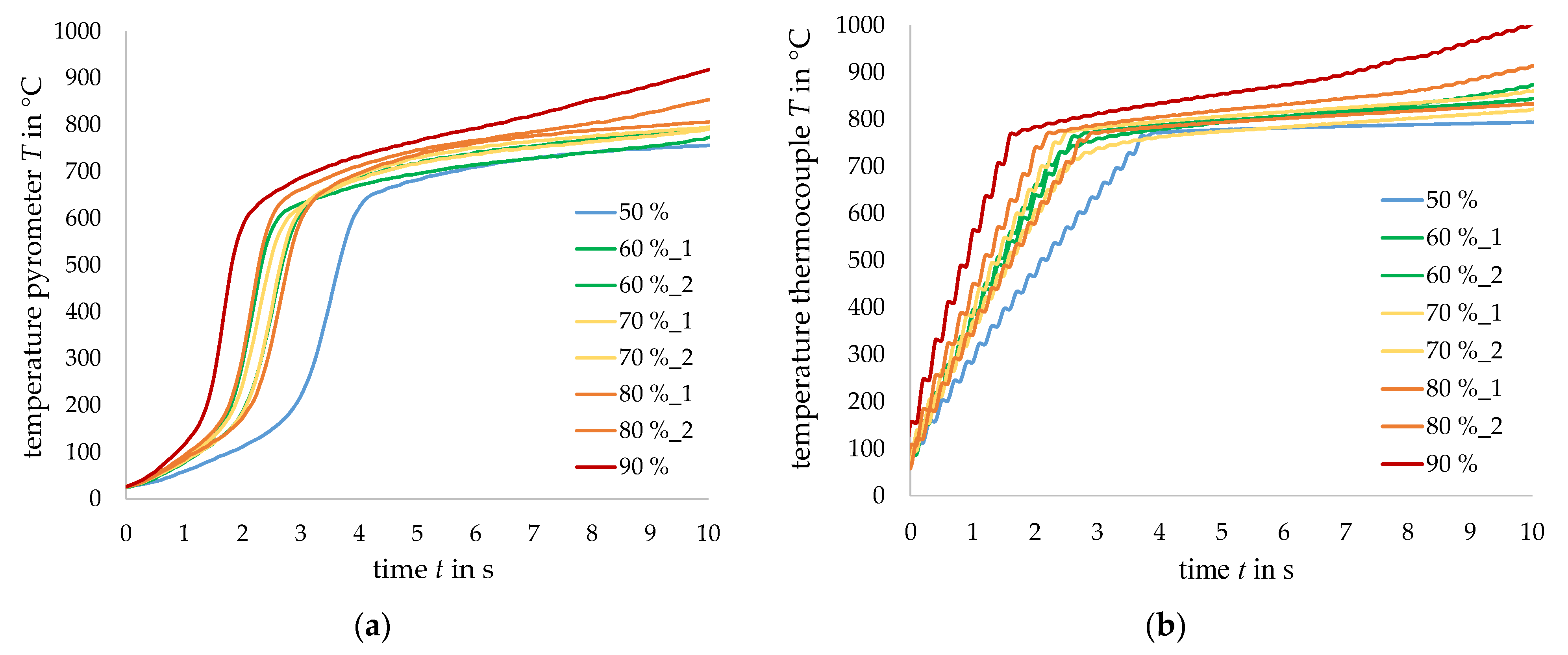
Overview of the Temperature-Time Curve: (a) Using a Pyrometer during Induction Heating of the Steel Sheet. (b) Using a Thermocouple during Induction Heating of the Steel Sheet.
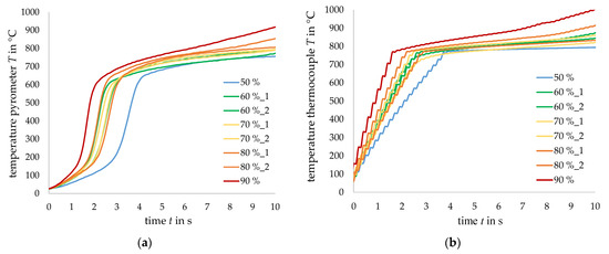
Figure 7.
Enlargement of the Graphs in Figure 6 in the initial part: (a) Pyrometer Measurement. (b) Thermocouple Measurement.
Due to the heating process, the sheets begin to scale more as the induction power increases. Using a protective gas like argon during the heating process in the casting tests should be implemented to protect the sheet and the compound zone from excessive oxidation. Furthermore, it can be seen in the photos that the heating time of 15 s provides sufficient heating of the compound zone. For this reason, the maximum heating time in the temperature measurements and the casting trials is set at 15 s. 100% power was not considered in the temperature measurements, as it has no relevance due to the increasing strength-reducing effect on the sheet.
Figure 6 shows the total overview of the temperature-time curves from the pyrometer (a) and thermocouple (b) measurements. The pyrometer measurements show that the curves are not increasing linear depending on the inductor power at 60, 70 and 80%. We see that after 15 s, at 50%, a temperature maximum of 780 °C and at 90%, a temperature maximum of 975 °C is reached for the pyrometer measuring. The temperature measuring range of the pyrometer is exceeded and results in a plateau in the curve. The thermocouple measurements also show that the curves are not linear to the inductor power. After 15 s, at 50%, a temperature maximum of 809 °C is reached and at 90%, a temperature maximum of 1180 °C.
The temperature kink after 15 s arises from the automatically set power cut-off of the inductor and results in a temperature drop during the measurement.
Figure 7 shows a detailed enlargement of Figure 6 of the initial part. Both measurements show a non-linear heating behaviour. Within the first 5 s, a substrate temperature of 682 °C is measured in the pyrometer measurement, and a substrate temperature of 778 °C is measured in the thermocouple measurement, both at a power of 50%. This difference can arise from the emission coefficient and is discussed in Section 4.
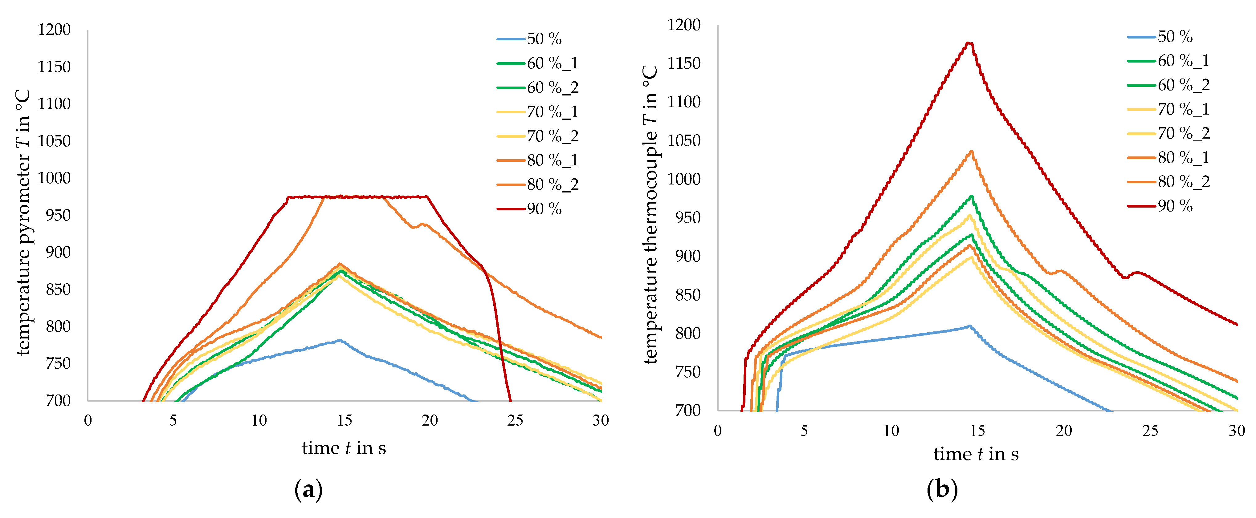
Figure 8 shows an expansion of the graphs of Figure 6 in the maximum temperature zone. The measuring limit of the pyrometer is at 975 °C, resulting in a plateau in the temperature measurement. The steep temperature drop at 90% may be due to the strong scaling of the sheet metal. With the thermocouple measurement, a temperature maximum of 1178 °C is reached after 15 s at 90%. After 5 s, sufficiently extensive heating of the compound zone is achieved so that the casting can take place from this point onwards. Lower powers are preferred to preload the sheet metal as little as necessary. Based on these results, an induction power of 50% and 70% is selected for the casting trials.
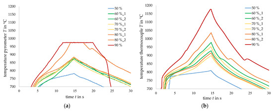
Figure 8.
Expansion of the Graphs in Figure 6 in the Maximum Temperature Zone: (a) Pyrometer Measurement. (b) Thermocouple Measurement.
3.2. Tensile Properties and Microstructure of Steel Sheets after Induction Heating
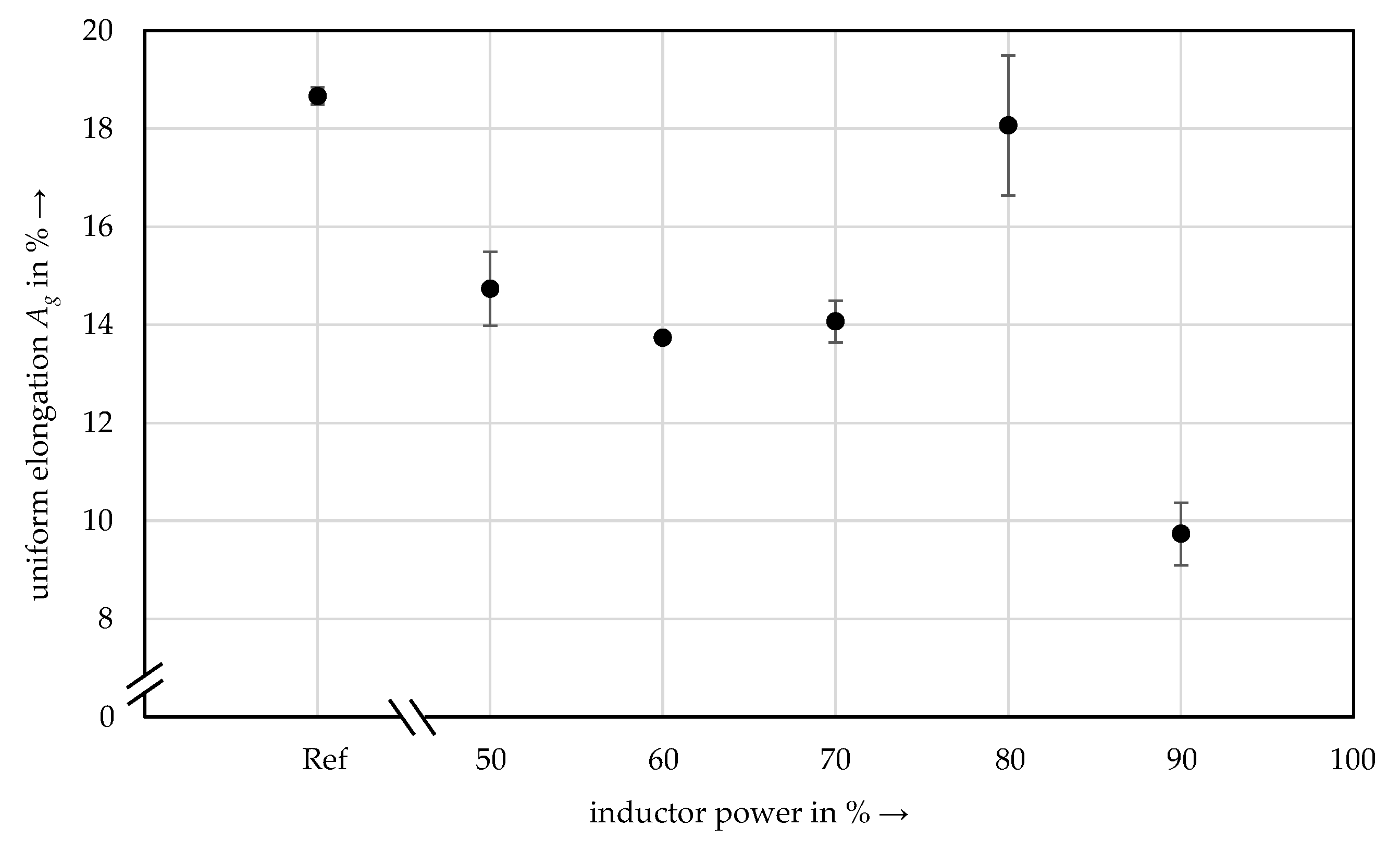
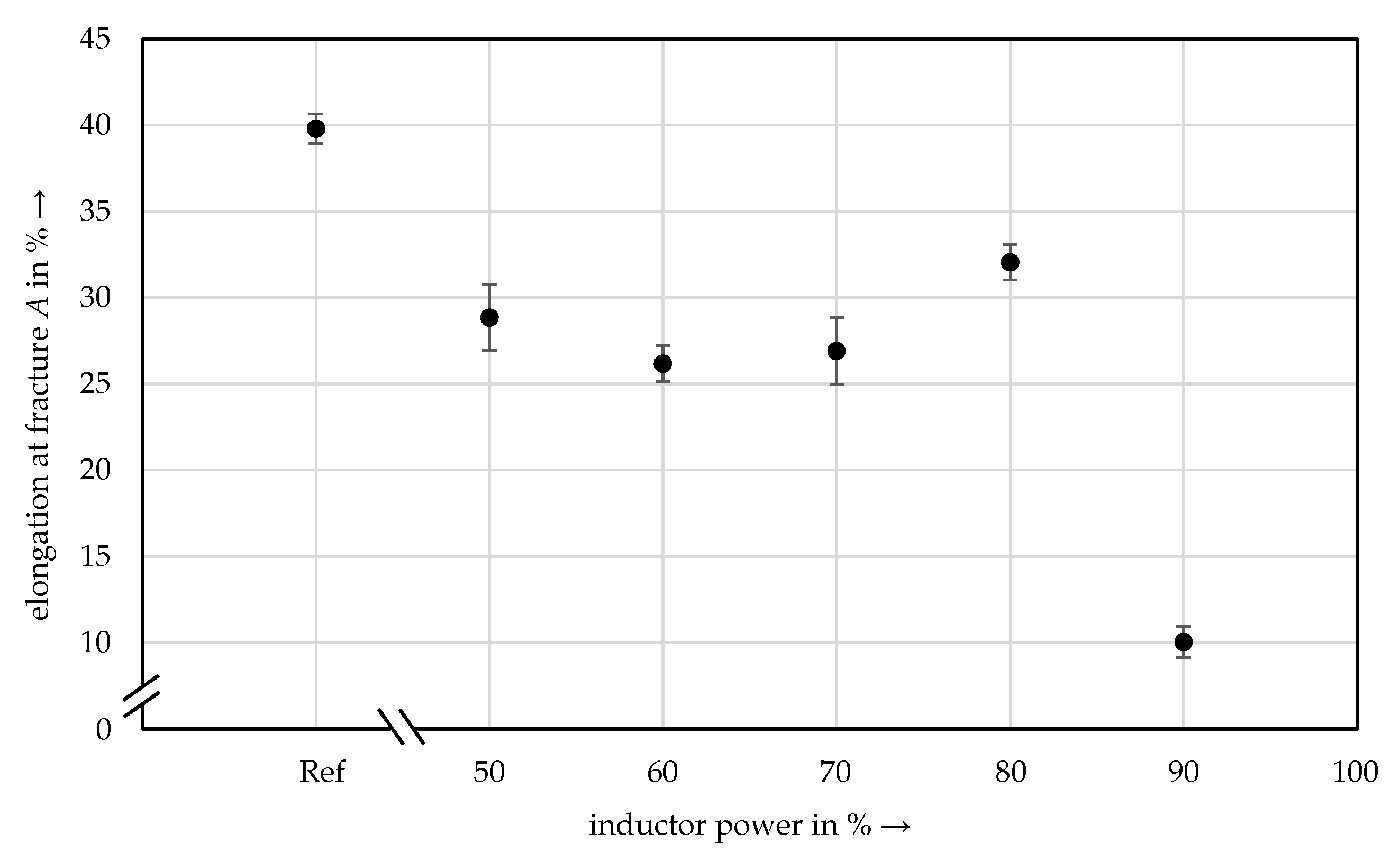
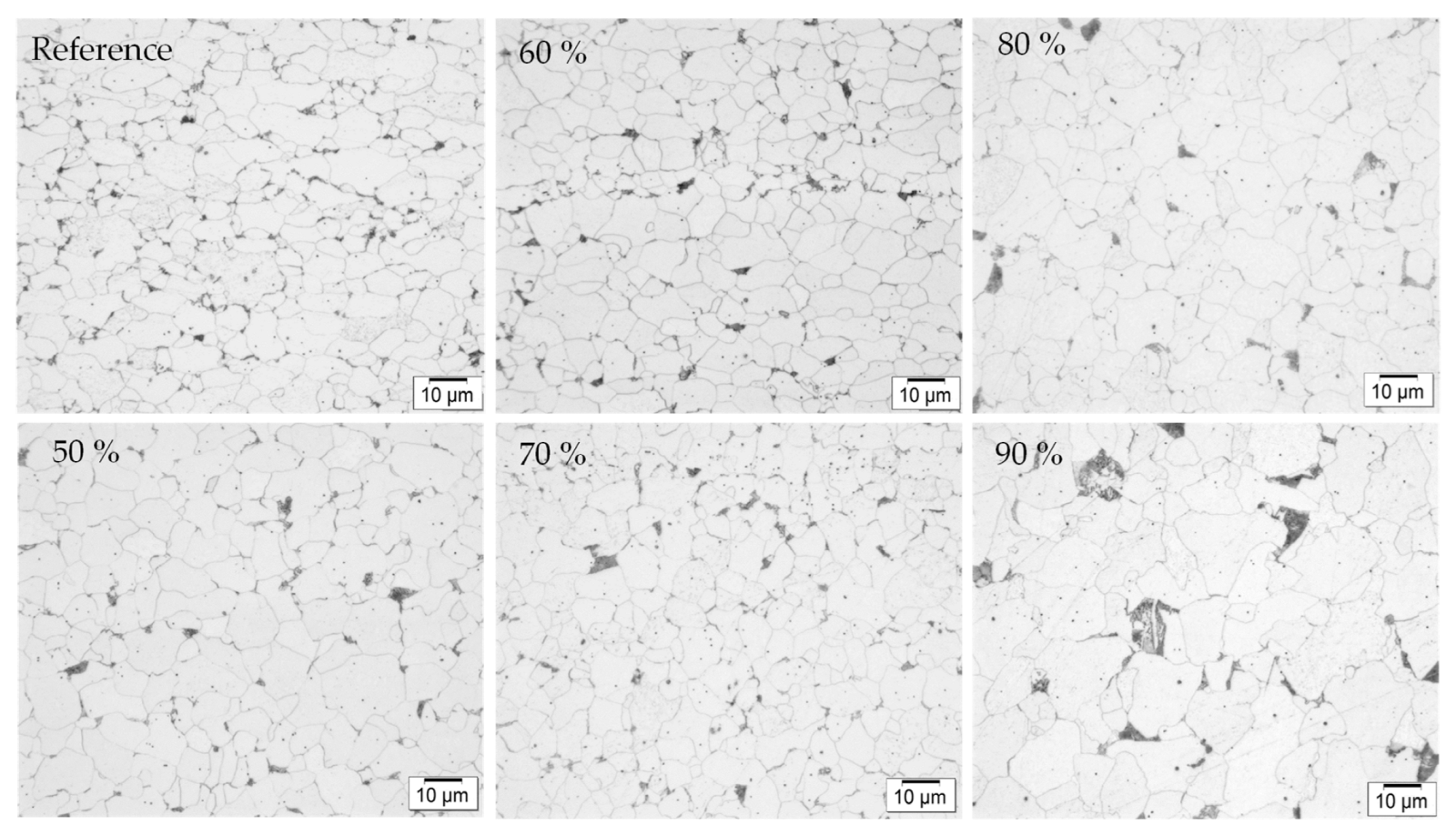
As expected, the tensile strength, the uniform elongation and the elongation at fracture show that the annealing treatment decreases the strength and the deformation capacity and indicates increasing embrittlement, Figure 9, Figure 10 and Figure 11. The reference sample has 435 MPa. The sample with 90% induction power has 407 MPa, a loss of around 7%. The uniform elongation of the reference sample is around 19% and decreases to 14% up to 70% induction power. At 80% induction power, the uniform elongation increases again. At 90% inductor power, the uniform elongation drops to around 10%, a total loss of nearly 50%. The elongation at fracture of the reference sample is 40% and decreases up to 27% at an induction power of 70%. At 80% induction power, the elongation at fracture is 32%. At 90% induction power, the elongation at fracture decreases to 10%, a total loss of about 25%. The strength losses correlate with the microstructural images in Figure 12. The grain size influences the strength and the ductility. Small grains are more resistant to deformation by external forces since the dislocation is stopped at the grain boundary. Bigger grains lead to a decrease in strength and ductility. The reference specimen was not exposed to inductive heating. The strength-reducing influence of induction heating on the steel sheet must be considered in the application’s design of aluminum/steel compound castings.

Figure 9.
Tensile Strength Rm of Inductive Heated Tensile Specimen.
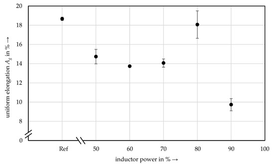
Figure 10.
Uniform Elongation Ag of Inductive Heated Tensile Specimen.
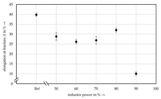
Figure 11.
Elongation at Fracture A in % of Inductive Heated Tensile Specimen.
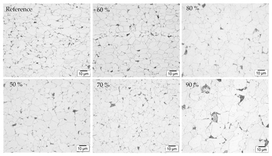
Figure 12.
Microstructural Changes due to Inductive Heating on Flat Tensile Specimens (1000× magnification).
3.3. Casting Results and Aluminum Casting Temperature in the Compound Zone
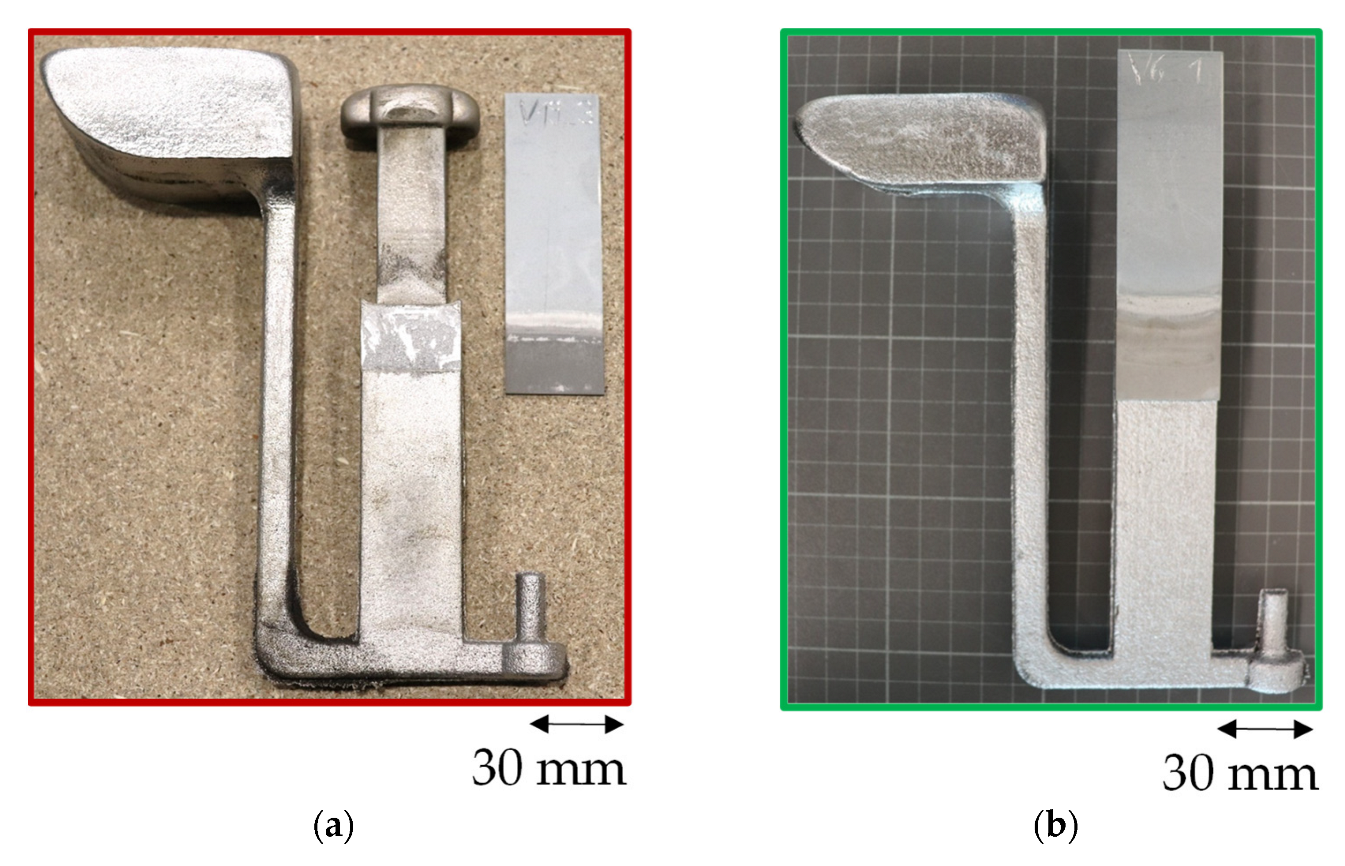
The overall results of the casting trials are shown in Figure 13. The reference tests with a casting temperature of 720 °C or 760 °C show that no material bonding could be achieved without preheating via induction. In contrast, an induction power of 50% and 70% with a casting temperature of 720 °C and 760 °C respectively achieved a material bond in the casting trials. The coated sheet metal substrates pre-treated by ablation cutting have resulted in a compound shear tensile specimen using the support of induction. Two of the three samples undergone testing and the third was used for metallographic investigation. The methodology proves that purely materially bonded aluminum-steel compound components can be produced using inductive heating.
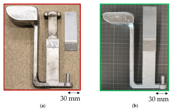
Figure 13.
Representative Results from the Casting Trials with Band Hot-Dip Zinc-Coated Sheet Metal HX340LAD+Z100. (a) Without Induction, no sufficient Material Bonding. (b) With Induction, a Material Bond occurred.
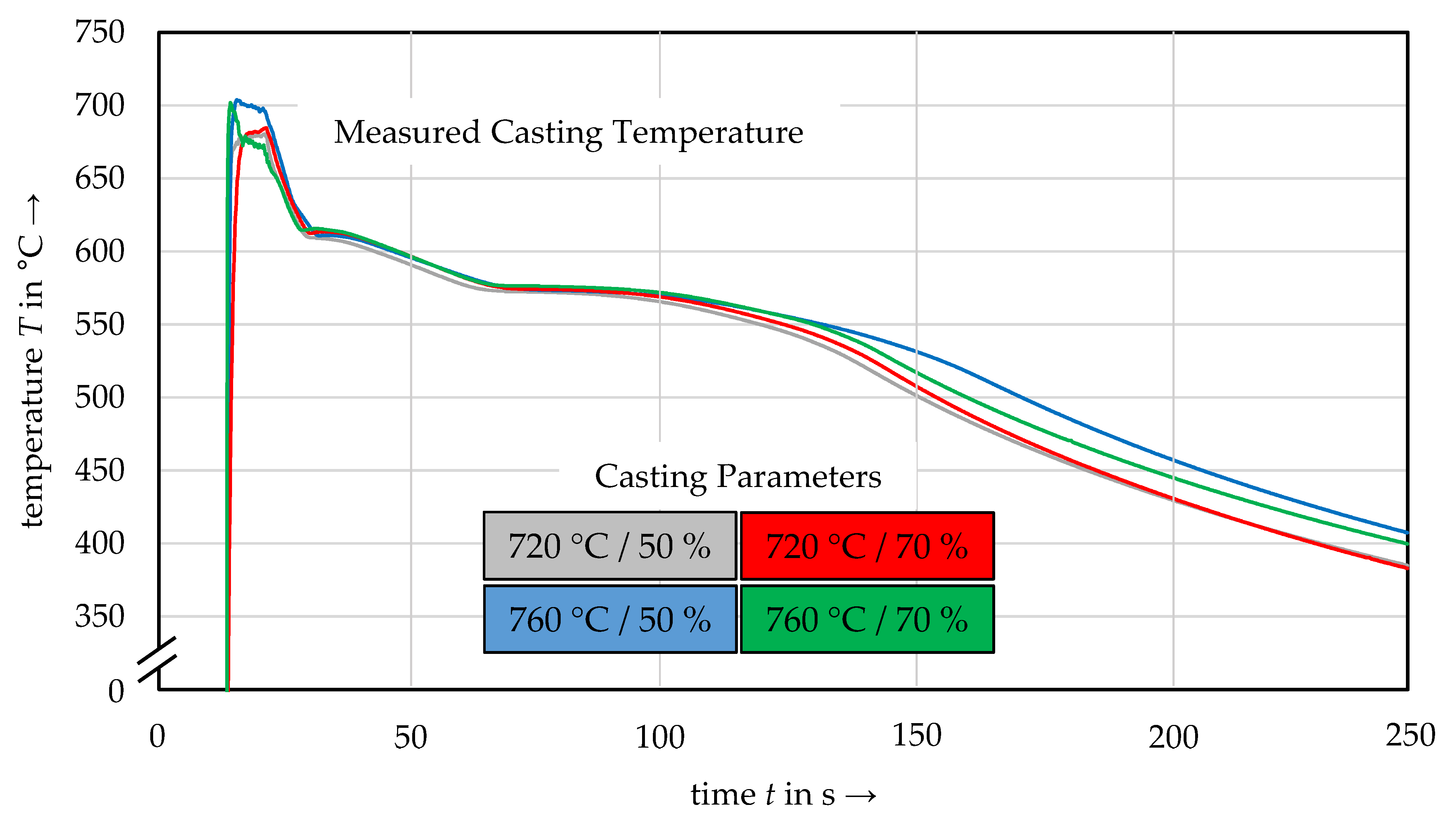
The compound zone measured melt temperature is significantly lower than the measured melt temperature before casting, Figure 14. The deviation is about 50 to 60 °C for all casting temperatures. A possible cause for the temperature loss could be the heat dissipation through the sand mould. Nevertheless, a material bond was achieved. The heated sheet causes a nearly constant temperature level due to the induction heating.
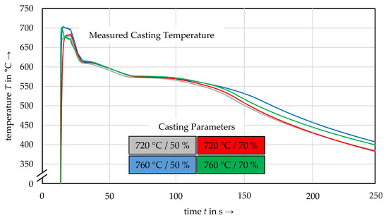
Figure 14.
Measured Aluminum Casting Temperature in the Area of the Compound Zone during the Casting Process.
3.4. Tensile Shear Strength of Aluminum/Steel Compound Specimen
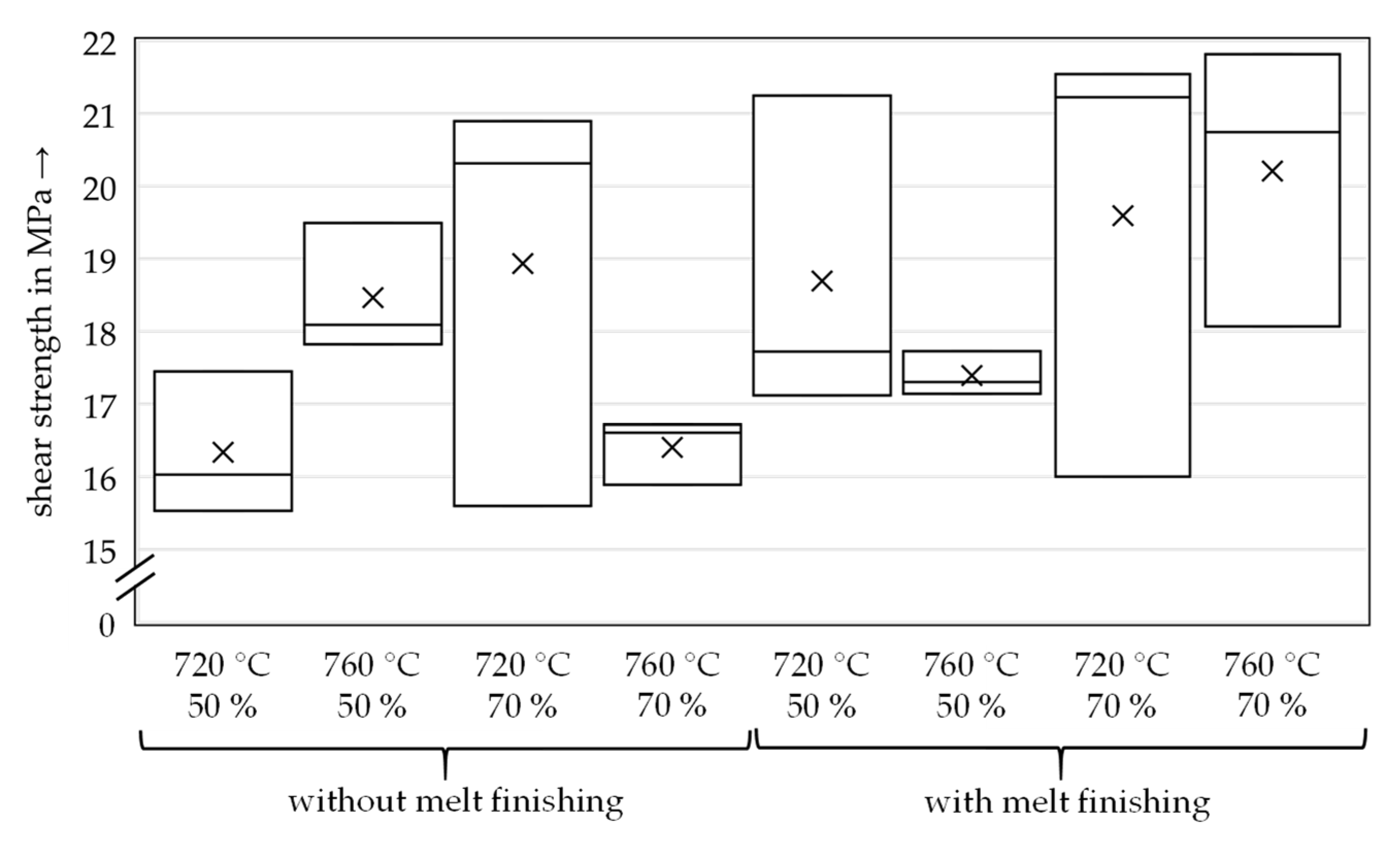
In Figure 15, the shear strength is plotted as a box-plot diagram. The bottom line represents the minimum value, the x represents the mean value, the top line represents the maximum value, and the line in the box represents the median value. For each parameter combination, three samples were tested. The results show no significant influence on the shear tensile strength in dependence on casting temperature, induction power or melt finishing agents (AlSr10, AlTi5B1). However, the database per parameter combination is small (3 per combination) and needs to be increased in future work.
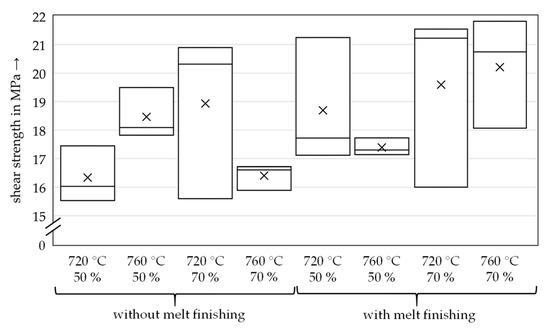
Figure 15.
Shear Tensile Strength of the Aluminum/Steel Compound Specimens.
The shear tensile strengths are generally above 15 MPa to 22 MPa. There were no casting defects in the fracture surfaces. All samples showed brittle fracture behaviour. The two specimens with laser surface engravings had a significantly lower maximum force of 8.3 MPa and 8.2 MPa than those without laser surface pre-treatment.
3.5. Microstructure of Aluminum/Steel Compound Samples
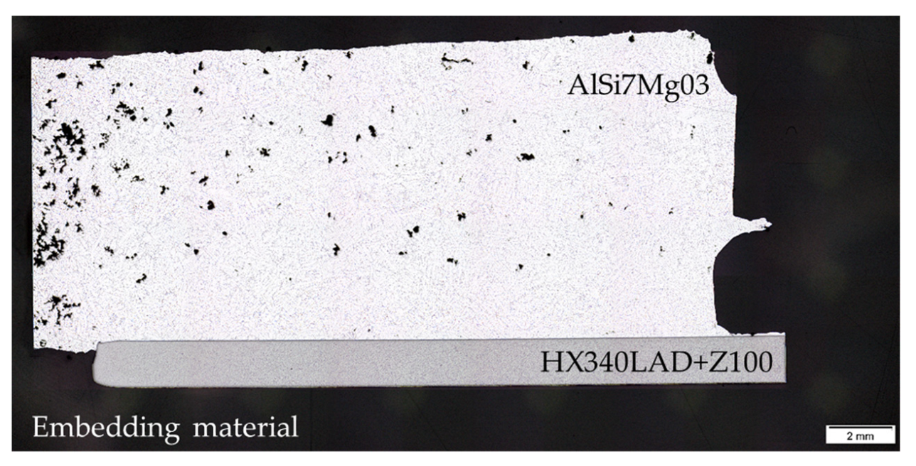
The overview image shows a material bond between the steel sheet and the aluminum casting, Figure 16. Microporosities are visible and distributed across the surface on the aluminum casting side. There could be different reasons for this. One reason could be the high heat development in the area of the compound zone melting off the zinc layer. Another reason could be the local burning of the furan binder during heating followed by gas development or dissolved gases in the aluminum melt that precipitates from solidification.

Figure 16.
Overview Image of an Aluminum/Steel Compound Casting Sample.
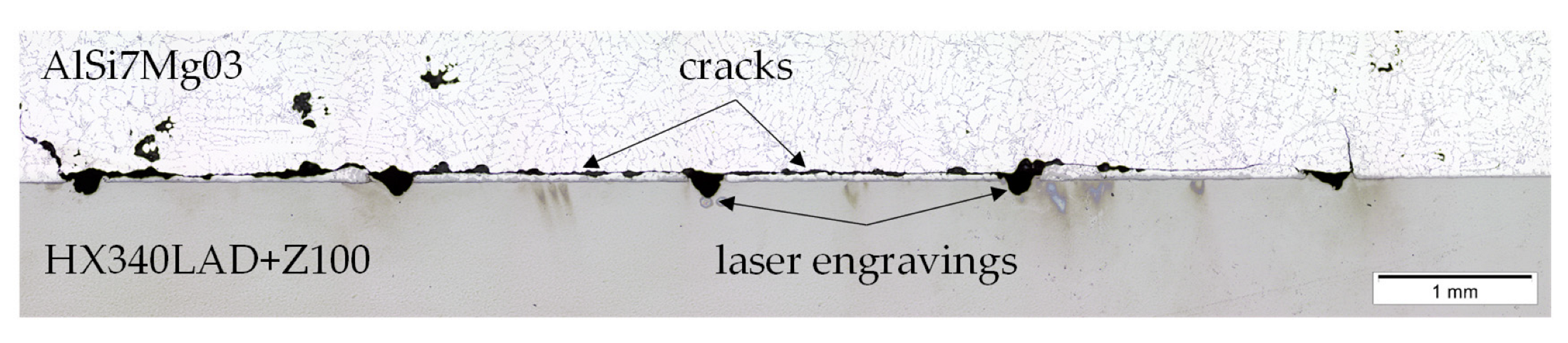
Figure 17 shows a section of a compound casting sample with a previous laser engraving of the sheet surface before the casting process. Cracks are visible between the ablation cutting lines along the side of the sheet near the compound bond zone. None of the lines was filled by the casting process so that no microform closure could be set. The cracks in the casting material are one explanation for the low maximum forces in the shear tensile test. Further explanation is that the removal of the coating reduces the wettability of the aluminum melt on the sheet and thus leads to imperfect bonding. Further, due to the different expansion coefficients, tensile stresses arise in the casting. The sharp edges of the engravings are preferred locations for crack initiation due to stress peaks. The engraving on the far right of the picture shows this perfectly. The sheet surface must be pre-treated before hot-dip zinc-coating to use laser structuring better.
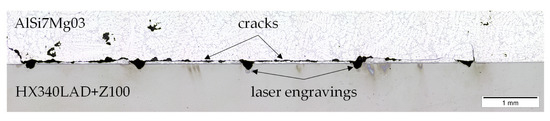
Figure 17.
Detail of an Aluminum/Steel Compound Casting Sample with a previous Laser Engraving of the Sheet Surface.
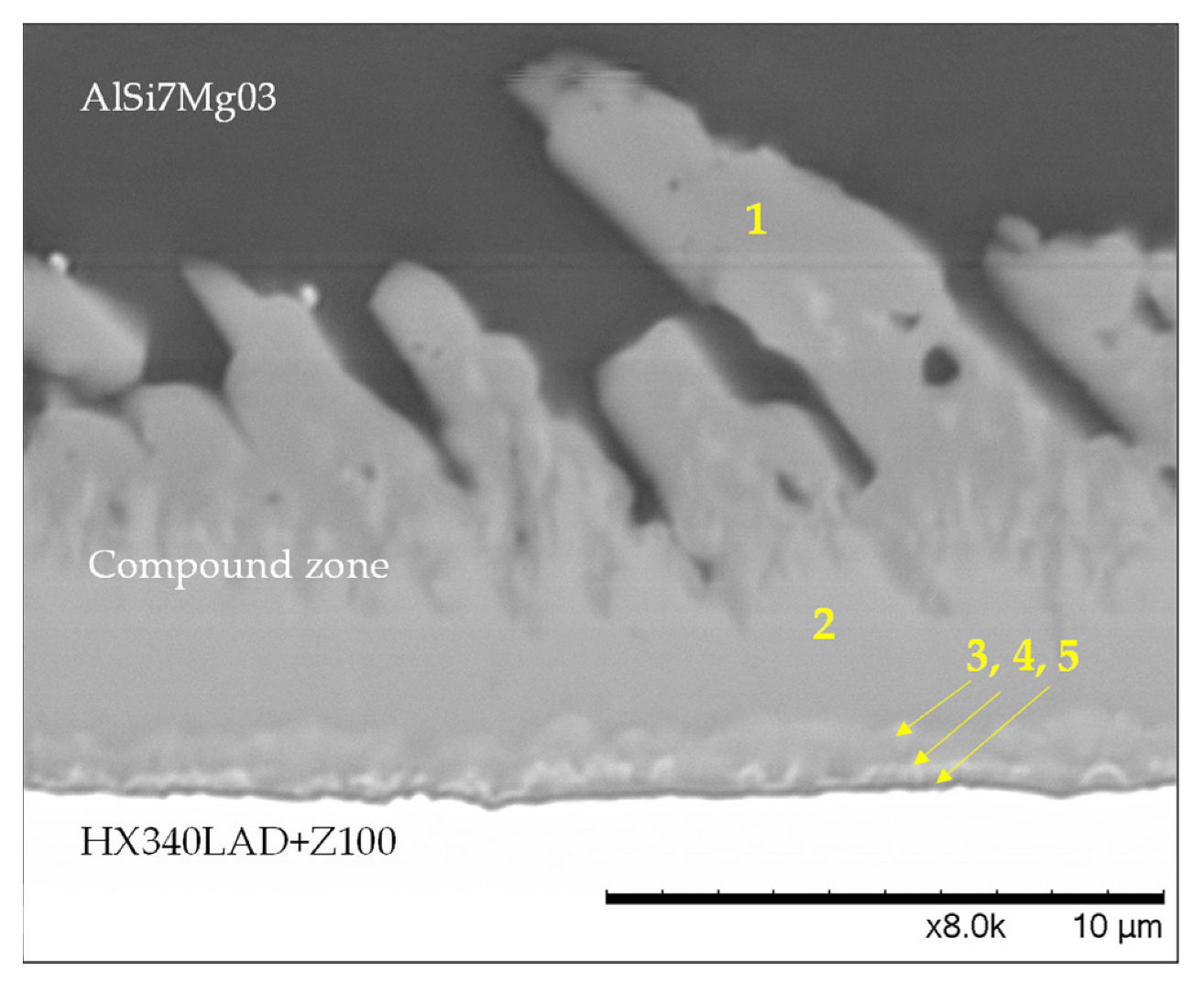
A more detailed image of the compound zone is shown in Figure 18. Five different intermetallic phases characterize the compound zone. Number 1 resembles the Al4.5FeSi phase with a tongue-like morphology, and number 2 indicates the Al7Fe2Si phase. Both phases were identified by EDX point measurement. The composition of phases 3 to 5 cannot be determined with certainty. However, they are visible due to their density differences. In the Bakke et al. [7] study, phases 1 and 2 were also determined. Phases 3 to 5 show contrast differences in the SEM image that are similar to the image presented in this study. The authors mention that the thin layers contain higher amounts of heavier elements like iron. However, a different composition could not be detected by the EDX. Instead, a similar composition was detected in the overlying layer. The findings are in line with the presented results. The EDX used in this study does not provide a high enough resolution. Further research needs to be carried out to determine the composition of phases 3 to 5. Due to the process, the zinc layer has completely dissolved from the sheet metal. The thickness of the compound zone is about 10 µm.
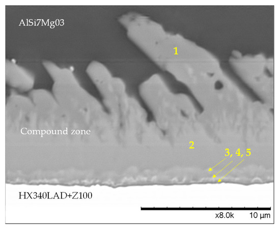
Figure 18.
SEM Image of an Aluminum/Steel Compound Zone with a Magnification of 8000×. Five Intermetallic Phases are visible. Phase 1: Al4.5FeSi, Phase 2: Al7Fe2Si, Phase 3 to 5 cannot be determined with certainty.
4. Discussion
The results of the heating behaviour of induction-heated steel sheets show that the sheet substrate temperatures with a power of 50% and 90% differ significantly from those with 60%, 70% and 80%. The flatter temperature bend after the steep temperature rise at the beginning is due to the reach of the Curie temperature resulting in the loss of the magnetic properties, Figure 7a,b. The inductor powers 60%, 70% and 80% showing a non-linear heating behaviour within the heating duration of 15 s. However, longer heating times have no practical relevance due to the strength-reducing effect on the sheet (see results in Section 3.2). There are several reasons against a longer induction heating time: One is the coarsening of the grains in the ferrite, and another is the dissolution of precipitates, especially with high inductor powers. At 50% induction power, it would be conceivable to heat longer without significant consequences due to the thermal stability of the precipitates. At 90% induction power, austenitization is accelerated and partial dissolution of precipitates may occur. Therefore, the high induction powers could be more problematic.
Comparing the temperature measurement methods has shown that the temperature measured using a thermocouple provides probably more precise temperature values than the pyrometer measurement, especially in the first 5 to 7 s of the heating period. The deviation of the pyrometer resulted from the emission coefficient ε, which was set to 0.62 during the measurement. However, the emission coefficient is strongly temperature-dependent. With increasing heating time, the pyrometer measurement converged against the thermocouple measurement. The direct coupling of the thermocouple ensured good heat conduction, which made it possible to record more precisely measured values.
As expected, the mechanical properties of the induction-heated steel sheets decrease. However, the overall loss of strength due to the induction heating is low.
The results of the casting trials show the necessity of preheating the coated sheet metal inserts to achieve good material bonding in 3D sand casting. Purely material-bonded compound specimens can be produced. Considering the sheet and casting temperature in total, 670 °C to 950 °C are reached at the compound zone within 15 s depending on the casting temperature and induction power combination. The temperature range and heating time are suitable to produce a sufficient material bond.
The shear tensile tests show that strengths between 15 MPa and 22 MPa are achieved. The influence of the parameter combination is insignificant due to the small sample size. Further research is needed to determine a significant influencing factor, for example, through a higher number of samples or increasing the inductor power from 70% to 90%. Samples without induction heating could not be tested since no bonding resulted.
Higher strengths were achieved compared to the study [10] with 7.7 MPa and similar sample geometry but with preheating the insert via plaster casting. However, the fracture behaviour was ductile compared to the present results due to the AlSi coating. The further investigated sand casting process did not produce a material bond. The same coating was investigated in high-pressure die casting using the casting alloy AlSi9MgMn [12]. Here, an average shear tensile strength of 11.3 MPa was achieved when the insert was preheated to 300 °C and showed ductile fracture behaviour. For comparison, tests were carried out with electro-galvanized zinc-coated hot rolled complex phase CPW 800 steel. Without preheating and a casting temperature of 685 °C, the results showed an average shear strength of 14.3 MPa. The same with a casting temperature of 750 °C resulted in average shear strength of 15.1 MPa. With preheating to 200 °C and a casting temperature of 750 °C, the average shear strength increased up to 18.3 MPa. The author states that the strength increase results from preheating the inserters. However, it needs to be clarified whether this is within the standard deviation. Compared to the Al-Si coating the fracture behaviour was brittle. Influencing the fracture behaviour of the aluminum/steel compound castings was not objective and should be investigated in future work. The investigated method in this study shows that comparable strengths to those obtained in high-pressure die casting can be produced despite different process characteristics. A compound could only be generated via inductive preheating of the coated inserts since no preheating is possible through the sand mould. The shear tensile specimens fabricated in [13] from gravity die casting showed an average shear tensile strength of 6 MPa. A bearing alloy Al12Sn4Si1Cu was used with a tin-coated carbon steel insert. The casting temperature was 720 °C, and sheet preheating via the metal mould was 350 °C. The results suggest brittle fracture behaviour. The shear strengths achieved in the present study are significantly higher.
In a study by Senff et al., steel/aluminum shear tensile specimens were machined with friction stir welding (FSW) in the area of the compound zone after the high pressure die-casting process. The FSW increased the strength of the joint from 15 MPa (without FSW) to around 40 MPa (with FSW on both sides) of the joint [14]. The FSW process could increase the strength of steel/aluminum joints from sand casting.
Laser engraving did not improve the shear strength due to the crack initiation by the engravings into the casting and reducing wettability. The casting did not fill the cavities, so microform-locking could not be achieved. For improvement, the sheet surface must be structured before applying the coating to utilize the strength-enhancing potential of the microform-locking. The reverse of the process steps would improve the wettability of the aluminum melt and, thus, the bonding effect through microform-locking. Casting around the sheet could also benefit microform locking during solidification because of the shrink fitting, resulting in a better performance.
5. Conclusions
With this method, it is possible to produce aluminum/steel compound castings in 3D sand casting. The production of shear tensile samples is impossible without using an induction unit and zinc-coating. In this study, the steel sheet must be band hot-dip zinc-coated. The shear tensile strength of the produced compound casting specimens reaches up to 22 MPa. Microform-locking did not occur through laser pre-treatment and reduced the wettability of the steel sheet. The shear tensile strength was lower than the specimens without laser pre-treatment. The process steps must be switched. The sheet must first be subjected to laser engraving and then to coating. In order to identify dominant process parameters, the number of specimens needs to be increased for statistical evaluation. This could also be investigated with a pull-out sample.
Author Contributions
Conceptualization, C.L.; methodology, C.L. and M.G. (Martin Guggemos); formal analysis, M.G. (Martin Guggemos), C.L. and M.G. (Maximilian Gruber); investigation, M.G. (Martin Guggemos), C.L. and M.G. (Maximilian Gruber); resources, L.M. (Lukas Mayr), L.M. (Lorenz Maier), M.G. (Maximilian Gruber) and T.W.; data curation, M.G. (Martin Guggemos), C.L. and M.G. (Maximilian Gruber); writing—original draft preparation, C.L.; writing—review and editing, M.G. (Martin Guggemos), M.G. (Maximilian Gruber), L.M. (Lorenz Maier) and L.M. (Lukas Mayr); visualization, C.L. and M.G. (Martin Guggemos); supervision, W.V. and D.G.; All authors have read and agreed to the published version of the manuscript.
Funding
This research received no external funding.
Data Availability Statement
The data presented are available on request from the corresponding author. The data are not publicly available since they are part of an ongoing study.
Conflicts of Interest
The authors declare no conflict of interest.
References
- Clausen, J. Hybrid and Compound Casting. Short Processing Times Thanks to Hybrid Castings—Ideal for Lightweight Construction. Available online: https://www.ifam.fraunhofer.de/de/technologien/hybridguss.html (accessed on 24 November 2022).
- Czerwinski, F. Current Trends in Automotive Lightweighting Strategies and Materials. Materials 2021, 14, 6631. [Google Scholar] [CrossRef] [PubMed]
- Olivier Dezellus, N. Eustathopoulos. Fundamental issues of reactive wetting by liquid metals. J. Mater. Sci. 2010, 45, 4256–4264. [Google Scholar] [CrossRef]
- Soderhjelm, C. Multi-Material Metal Casting: Metallurgically Bonding Aluminum to Ferrous Inserts; Worcester Polytechnic Institute: Worcester, MA, USA, 2017; Available online: https://digital.wpi.edu/show/j6731396q (accessed on 6 December 2022).
- Bakke, A.O.; Arnberg, L.; Løland, J.-O.; Jørgensen, S.; Kvinge, J.; Li, Y. Formation and evolution of the interfacial structure in al/steel compound castings during solidification and heat treatment. J. Alloys Compd. 2020, 849, 156685. [Google Scholar] [CrossRef]
- Bakke, A.O.; Nordmark, A.; Arnberg, L.; Li, Y. Interfacial microstructure formation in A356/steel compound castings using metal coating. MATEC Web Conf. 2020, 326, 6005. [Google Scholar] [CrossRef]
- Bakke, A.O.; Nordmark, A.; Arnberg, L.; Li, Y. Sn-Aided Joining of Cast Aluminum and Steel Through a Compound Casting Process. Met. Mater. Trans. B 2021, 53, 60–70. [Google Scholar] [CrossRef]
- Shin, J.; Kim, T.; Lim, K.; Cho, H.; Yang, D.; Jeong, C.; Yi, S. Effects of steel type and sandblasting pretreatment on the solid-liquid compound casting characteristics of zinc-coated steel/aluminum bimetals. J. Alloys Compd. 2018, 778, 170–185. [Google Scholar] [CrossRef]
- Bao, Z.; Wang, S.; Han, R.; Tang, M.; Zhao, C.; Zhang, H. Microstructure and mechanical properties of aluminum/steel bimetal using compound casting with electroless nickel plating. Mater. Res. Express 2021, 8, 016517. [Google Scholar] [CrossRef]
- Fang, X.; Gundlach, J.; Schipperges, J.-J.; Jiang, X. On the Steel–Aluminum Hybrid Casting by Sand Casting. J. Mater. Eng. Perform. 2018, 27, 6415–6425. [Google Scholar] [CrossRef]
- Kleiber Infrared. Emissivity Table. Available online: https://www.kleiberinfrared.com/index.php/de/amanwendungen/emissionsgrade.html (accessed on 5 January 2023).
- Fang, X. Evaluation of Coating Systems for Steel Aluminum Hybrid Casting. J. Mater. Sci. Eng. A 2017, 7, 51–67. [Google Scholar] [CrossRef]
- Ramadan, M.; Subhani, T.; Rajhi, W.; Ayadi, B.; Al-Ghamdi, A.S. A Novel Technique to Prepare Cast Al-bearing alloy/Wrought Steel Bimetallic Specimen for Interfacial Shear Strength. Int. J. Eng. Adv. Technol. 2020, 9, 3322–3326. [Google Scholar] [CrossRef]
- Senff, M.; Volk, W. Hybrid joining of cast aluminum and steel by compound casting and friction stir welding. Prod. Eng. 2023. [Google Scholar] [CrossRef]


Disclaimer/Publisher’s Note: The statements, opinions and data contained in all publications are solely those of the individual author(s) and contributor(s) and not of MDPI and/or the editor(s). MDPI and/or the editor(s) disclaim responsibility for any injury to people or property resulting from any ideas, methods, instructions or products referred to in the content. |
© 2023 by the authors. Licensee MDPI, Basel, Switzerland. This article is an open access article distributed under the terms and conditions of the Creative Commons Attribution (CC BY) license (https://creativecommons.org/licenses/by/4.0/).