Abstract
To investigate the feasibility of using absorbable Mg alloy pedicle screws for atlantoaxial dislocation fixation, four types of Mg alloy pedicle screws of different thread forms were designed, and simulation analysis of the pull-out force was performed using the finite element method. Stress and displacement distributions of the atlantoaxial fixation model were obtained. Subsequently, screw samples were prepared using the WE43 Mg alloy for extraction, torsion, and immersion corrosion tests. Finite element analysis results showed that the pull-out forces of triangular, rectangular, trapezoidal, and zigzag thread screws were 552.61, 540.91, 546.4, and 542.74 N, respectively, and the stresses on the screws were 146, 185, 195, and 265 MPa, respectively, when they were pulled out. In other words, the triangular thread screw had the largest pull-out resistance and smallest stress peak. The average corrosion rate of Mg alloy screws in vitro was 0.46 mg·cm−2·day−1. Compared with that before corrosion, the extraction resistance of the corroded screws did not change significantly; however, the torsional strength decreased, but it was still greater than the torque required for screw implantation. It can be concluded that triangular thread Mg alloy pedicle screws have good extraction resistance and mechanical stability and can meet the load-bearing requirements for atlantoaxial dislocation fixation. The degradation of the Mg alloy reduced the mechanical strength of the screws, but the triangularly threaded screws can still maintain their effectiveness.
1. Introduction
Owing to congenital malformations, trauma, tumors, etc., atlantoaxial dislocation often occurs in the pediatric population, causing patients to suffer from head and neck pains, abnormal muscle tone, muscle atrophy, unstable gait, etc. [1,2,3]. Moreover, because there is a spinal cord penetrating the atlantoaxial conus foramen and a vertebral artery penetrating the transverse foramen, atlantoaxial dislocation distorts the vertebral artery, causing ischemia of the basilar artery and compression of the spinal cord, resulting in spinal cord injury. If the spinal cord compression is not released as soon as possible, the patient will become tetraplegic and may even suffer a life-threatening condition [4,5]. Atlantoaxial pedicle screw internal fixation is an effective surgical procedure for atlantoaxial dislocation [6,7,8]. Currently, this procedure is performed using pedicle screws made from inert metals such as titanium and stainless steel, which have disadvantages such as stress shielding, accumulation of metallic toxic substances, and the requirement for secondary surgery to remove implants [9]. Fabricating pedicle screws from biodegradable metals, instead of inert metals, can be an ideal solution to these problems.
Mg and Mg alloys are considered potential biodegradable metal materials, and their degradable properties can eliminate the requirement for the secondary surgical removal of implants. Moreover, Mg ions produced during the degradation process of Mg implants are beneficial to the human body. Mg2+ is the fourth most abundant cation in the human body and can regulate signal transduction, energy metabolism, and cell proliferation. In bone tissue, it enhances bone growth and bone strength [10,11]. Adults consume 300–400 mg of Mg daily, and the excess is excreted through urine [12]. In terms of biomechanical properties, an Mg alloy has a density of 1.74~2 g/cm3 and an elastic modulus of 41–45 GPa, which is closer to that of natural bone tissue (1.8~2.1 g/cm3, 3–20 GPa), compared to a titanium alloy and medical stainless steel; therefore, Mg-based orthopedic implants can reduce the stress shielding effect [13,14]. However, the uncontrollable degradation rate of Mg alloys in biological environments limits their biomedical applications. Body and blood environments containing chloride ions accelerate the corrosion of Mg alloys [15]. If the Mg alloy corrodes fast, the mechanical properties of the implants will be reduced before the tissue heals completely. Moreover, the degradation of Mg alloys is accompanied by hydrogen precipitation reactions, and H2 generated by the corrosion of Mg and Mg alloys is collected in the air pockets near the implant to prevent the tissue from healing [16,17]. The degradation of Mg alloys also causes alkalization of nearby areas [18], which can adversely affect the pH-dependent physiological responses. For these reasons, the biomedical application of an Mg alloy should reduce its corrosion rate such that the body can gradually adapt to the reaction process of the Mg alloy without affecting the normal physiological activities of the conditions of absorption and discharge of Mg alloy degradation products, to ensure good biocompatibility and mechanical properties of Mg alloy implants.
To date, the main methods of improving the corrosion resistance of Mg alloys include micro-alloying [19,20,21], heat treatment [22], surface coating [23], and structural design. Adding rare earth elements such as Y, Gd, and Sc to Mg alloys improves and compensates for their deficiencies [24]. Lü et al. [25] found that rare earth elements play an important role in the solid solution strengthening of Mg alloys. Gusieva et al. [26] summarized the role of rare earth elements in grain refinement and the improvement of the corrosion resistance of Mg alloys. The WE43 Mg alloy is a typical rare earth Mg alloy with improved strength, heat, and corrosion resistance owing to the multi-strengthening effect of rare earth elements.
This study addresses the repositioning and fixation of atlantoaxial dislocations. To study the extraction resistance of Mg alloy pedicle screws and their mechanical performance in the atlantoaxial fixation system, a simulation of the Mg alloy screws was performed using Ansys 19.2 (ANSYS, Canonsburg, PA, USA), the finite element analysis software. The WE43 Mg alloy was used as the raw material to make pedicle screws, and the mechanical and degradation properties of the Mg alloy screws were investigated to guide the clinical application of the Mg alloy atlantoaxial fixation system.
2. Materials and Methods
2.1. Geometry of Models
2.1.1. Geometry of the Models of Screws
Parameters such as screw diameter, length, and thread form affect the screw strength. The larger the diameter and length of the screw, the higher its holding strength. However, a larger diameter poses a risk of bone rupture, and a longer length may pass through the cortical bone layer and damage the vertebrae. In this study, we designed screws with a length of 27.6 mm, an outer diameter of 3.8 mm, a pitch of 1.2 mm, and a tooth thickness of 0.5 mm. Four shapes (triangular, rectangular, trapezoidal, and zigzag thread forms) were selected according to the shapes of internal fixation screws used in clinical applications, as shown in Figure 1.
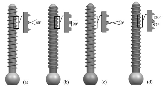
Figure 1.
Four types of screws with different thread shapes: (a) triangle; (b) rectangle; (c) trapezoid; and (d) zigzag.
2.1.2. Atlantoaxial Fixation System
Computed tomography (CT) images of the C0–3 cone of the neck were acquired from a volunteer (female, 62 years old) with a normal upper cervical spine, and a three-dimensional (3D) reconstruction of the atlantoaxial spine was completed using Mimics 20.0, which was optimized in Geomagic Studio 2013. The fixation system was designed and assembled with the atlantoaxial spine using UG 10.0 software (Figure 2). Zhang et al. [27] showed that better cervical sagittal balance and clinical outcomes could be achieved after atlantoaxial fixation with a C0-C2 angle of 10–20°. In this study, the nail entry point was located at the intersection of the mid superior, approximately 1/4 the horizontal line, and the mid external, approximately 1/4 the vertical line on the lateral posterior surface of the atlantoaxial spine, with an appropriate angle of inward tilt to improve fixation stability.
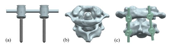
Figure 2.
Atlantoaxial fixation system model: (a) screw frame; (b) atlantoaxial joint; and (c) fixation. system.
2.2. Static Structure Finite Element Analysis
The assembled model of the atlantoaxial fixation system was imported to ANSYS Workbench 19.2 software for static structure finite element analysis.
2.2.1. Material Parameters
The pull-out resistance of the screws was analyzed according to the experimental requirements found in ASTM F543 using a polyurethane block with dimensions of mm3, into which the screws were inserted vertically to a depth of 20 mm. According to the information provided by the manufacturer (Enjy-tech, Beijing, China), the compressive strength of the polyurethane was 7.12 MPa, the tensile strength was 5.90 MPa, and the shear strength was 3.89 MPa. The WE43 Mg alloy that was used to make the screws had a tensile strength of 304 MPa, yield strength of 287.76 MPa, and torsional strength of 0.27 MPa. The atlas and axis were considered as the cortical bone. The material parameters for each component are listed in Table 1.

Table 1.
Material parameters.
2.2.2. Meshing
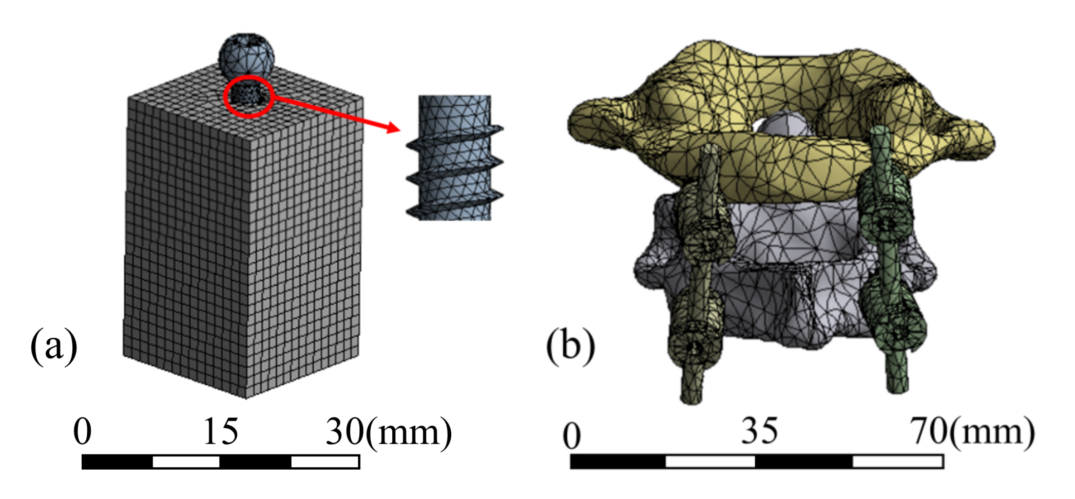
The screw frame meshed with tetrahedral and hexahedral cells, and 108,194 elements were delineated. The atlantoaxial spine was meshed using tetrahedral cells with 112,357 elements. The test block was meshed with hexahedral cells with 24,118 elements. The mesh of the two models and details of the screw are shown in Figure 3.
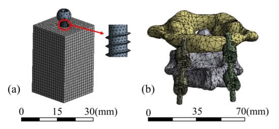
Figure 3.
Mesh models of (a) pull-out test and (b) atlantoaxial fixation system.
2.2.3. Loads and Boundary Conditions
1. Pull-out test
Because the pitch of the pedicle screw designed in this study is 1.2 mm, when the pedicle screw undergoes an axial displacement greater than one pitch, it can be regarded as the screw being pulled out. Therefore, in the pull-out force analysis, a displacement of 1.5 mm was applied to the head of the screw along the axial direction of the screw outward, and the displacement in other directions was set to zero. The screw and polyurethane block had a frictional contact; the contact formulation was surface-to-surface, with a friction factor of 0.15.
2. Atlantoaxial fixation system
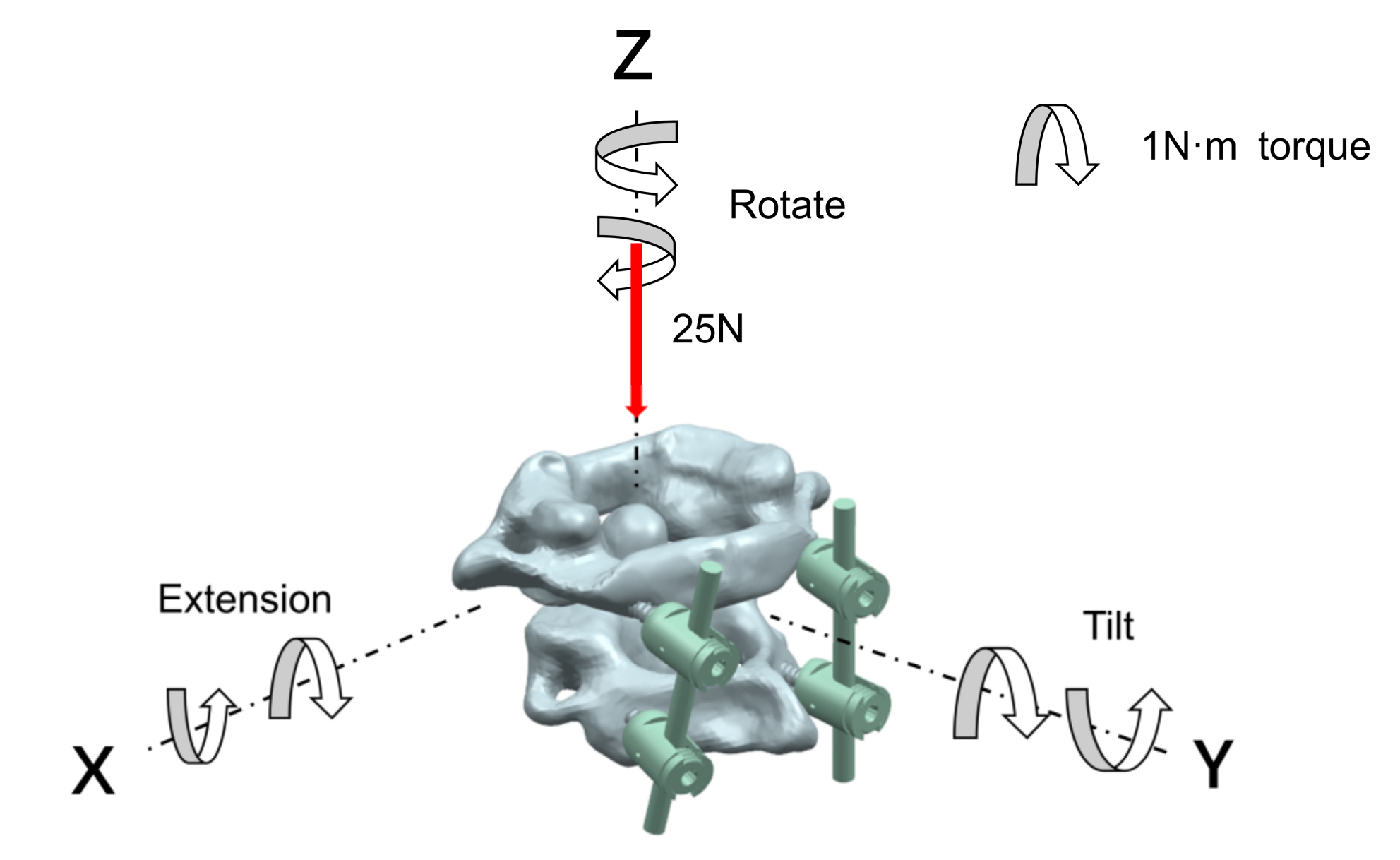
In the analysis of the atlantoaxial fixation system, for the state of a neck being upright, a fixed restraint was applied to the base of the axis, and a vertical downward load of 25 N was applied to the atlas to simulate the weight of the head; for the state of the neck being in motion, the center of gravity of the atlantoaxial spine was used as the center of motion, and a 1 N·m moment was applied to the point in the x, y, and z axes to analyze the extension, rotation, and tilt movement of the neck, respectively. The neck-movement patterns and loads are shown in Figure 4.
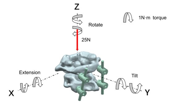
Figure 4.
Neck-movement patterns and loads.
2.3. Sample Preparation
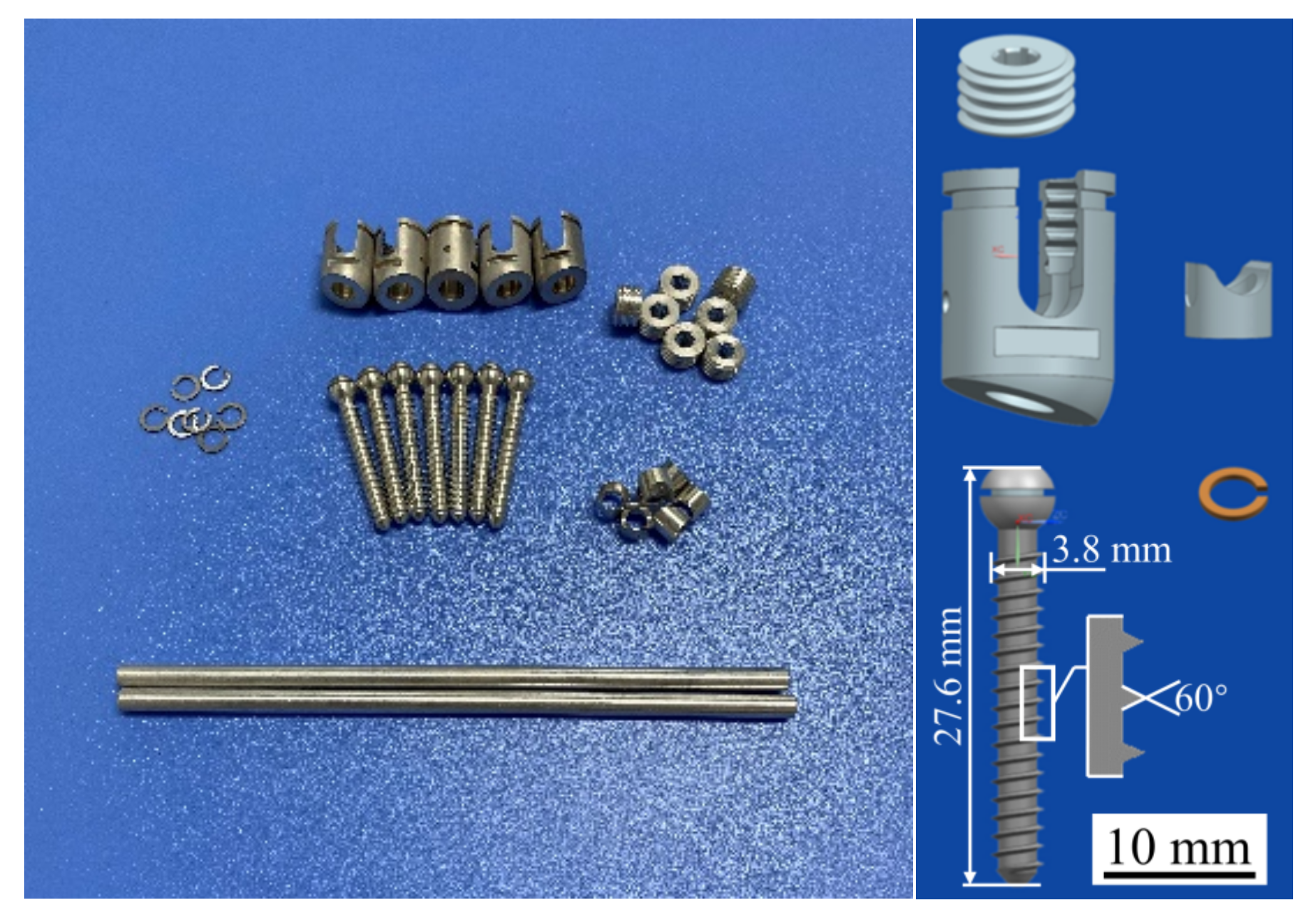
Triangular thread screws and their accessories were prepared using the WE43 Mg alloy, as shown in Figure 5. The WE43 Mg alloy was purchased from the material supplier (Suzhou Chuanmao Metal Material Co., Ltd., Suzhou, China), and its alloying elements are listed in Table 2, in which the rare earth elements Y (4.05%) and Gd (1.17%) can improve the corrosion resistance of Mg alloys. After the sample was treated with a polishing solution, the surface roughness of the screw satisfied the requirements of Ra1.6. Polishing can also produce a dense and uniform oxide film on the surface of the Mg alloys, which protects the internal metal from further oxidation and corrosion and improves the corrosion resistance of these alloys.
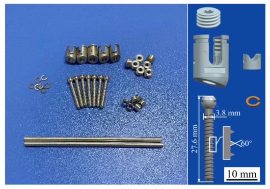
Figure 5.
Mg alloy pedicle screws and their accessories.
Table 2.
Elemental composition of the WE43 Mg alloy (%).
2.4. Performance Test
2.4.1. Pull-Out Strength Test
The pull-out strength of the screw was tested, as shown in Figure 6. A pilot hole with a diameter of 2.5 mm was drilled perpendicular to the surface of the test block before the screw was installed, and the screw was screwed at a speed of 3 r/min to a depth of 20 mm. The pull-out process was performed using a tensile tester (Instron 5565, Boston, MA, USA), and the screw hole, screw, and fixture were on the same axis during this process. A tensile load was applied to the screw head at a rate of 5 mm/min.
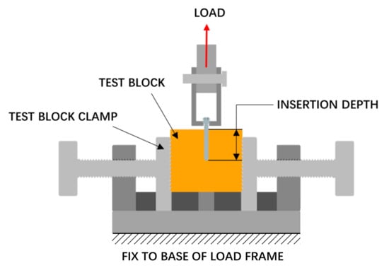
Figure 6.
Pull-out strength test setup.
2.4.2. Torsional Strength Test
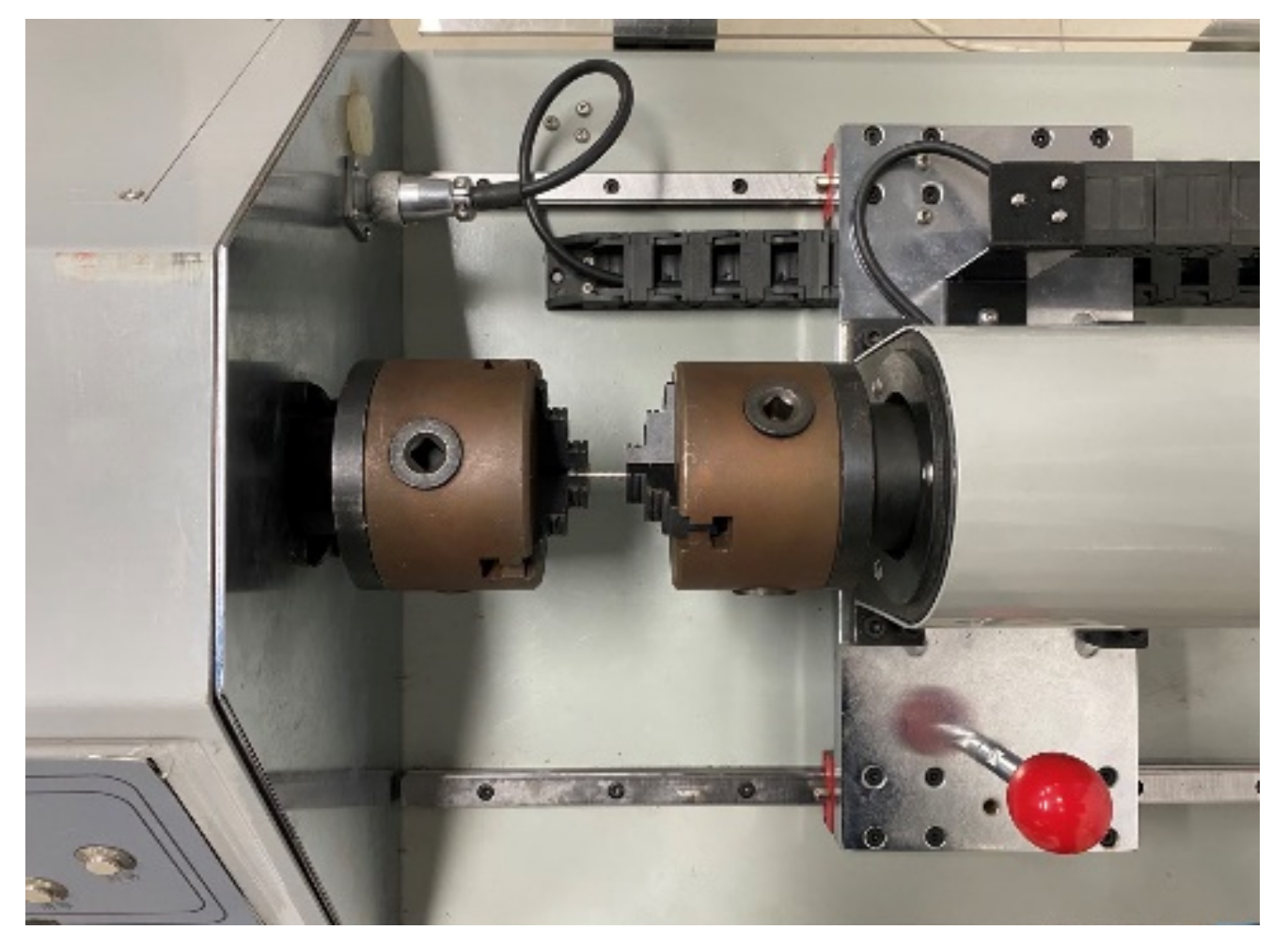
The torsional strength of the screws was tested according to ASTM F543, and the test equipment is shown in Figure 7. The screw was placed in the fixture of the torsion tester (Fuletest, Shanghai, China), exposing five to eight turns of the threads below the head of the screw. Torque was applied to the screw at 3 r/min. The torsion angle and torque value were recorded to obtain the yield torque, maximum torque, and breaking torsion angle of the screws.

Figure 7.
Torsional strength test setup.
2.4.3. Immersion Test
The immersion test of the Mg alloy screws was conducted according to ASTM G31, and the test setup is shown in Figure S1. Six samples of Mg alloy screws were obtained, cleaned using anhydrous alcohol, dried, and weighed. Hank’s balanced salt solution was chosen to simulate the body fluids, and its main constituents are listed in Table 3. According to standard requirements, the ratio of the test solution volume (ml) to the surface area of the specimen (mm2) σ should be greater than 0.20, and the volume of the solution used in the test was 350 mL (σ = 0.87). The pH of the solution was adjusted to 7.4 using NaHCO3, and the solution was placed in a constant-temperature chamber at 37 °C. After immersing the screws in Hank’s solution, the volume of H2 and the pH of the solution were recorded every 24 h, and the solution was changed. The experiment was performed for 14 d. After completing the immersion test, the screw surface was blown dry to obtain macroscopic corrosion samples. The microscopic samples were observed using a scanning electron microscope (SEM, ZEISS, Baden-Wurttemberg, Germany), and the corrosion products were analyzed through energy dispersive spectrometry (EDS, Oxford Instruments, Oxford, UK). According to ASTM G1, the screws were sequentially ultrasonically cleaned using a 90–100 °C 20 wt% chromic acid solution, distilled water, and alcohol, and then it was dried and weighed. The average corrosion rate (v) of the sample was calculated according to Equation (1):
where W0 (g) is the original weight of the screw, W1 (g) is the weight of the screw after the corrosion products are washed away, S (cm2) is the surface area of the screw exposed to Hank’s solution, and T (h) is the immersion time.
Table 3.
Components of Hank’s solution (g/L).
3. Results
3.1. Simulation Analysis Results
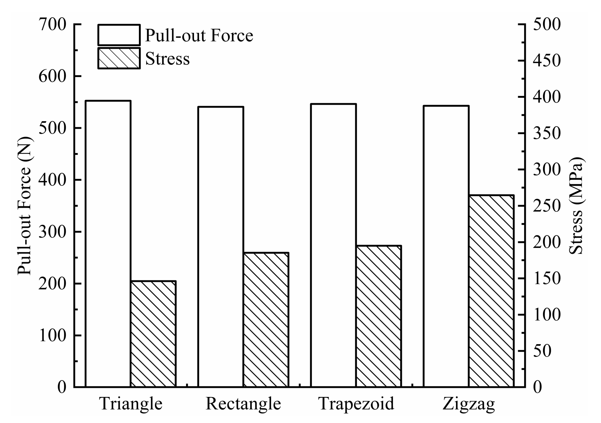
The pull-out force acting on the screws and the maximum equivalent stress on the screws are shown in Figure 8. For the four types of threads (triangular, rectangular, trapezoidal, and zigzag), the extraction force on the triangular thread screw is the largest (552.61 N), and the stress is the smallest (146.20 MPa), indicating that the triangular thread screw is the most difficult to extract and is subjected to a more uniform load, which is less likely to cause damage. A possible reason for the good extraction resistance of the triangular threaded screw is that it cuts bone trabeculae during the screwing process, which generates more friction. In contrast, the screwing process of the other three threaded screws mainly relies on compressing bone tissue to generate more torque, but the increase in torque does not improve the extraction resistance of the screw.
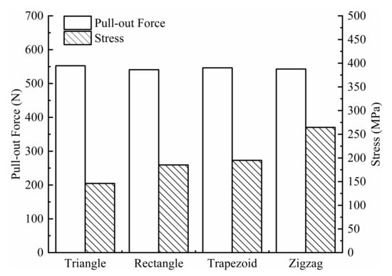
Figure 8.
Pull-out force and stress for four types of screws.
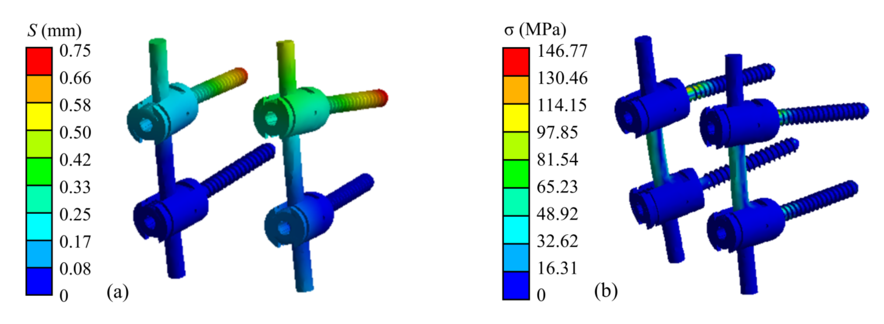
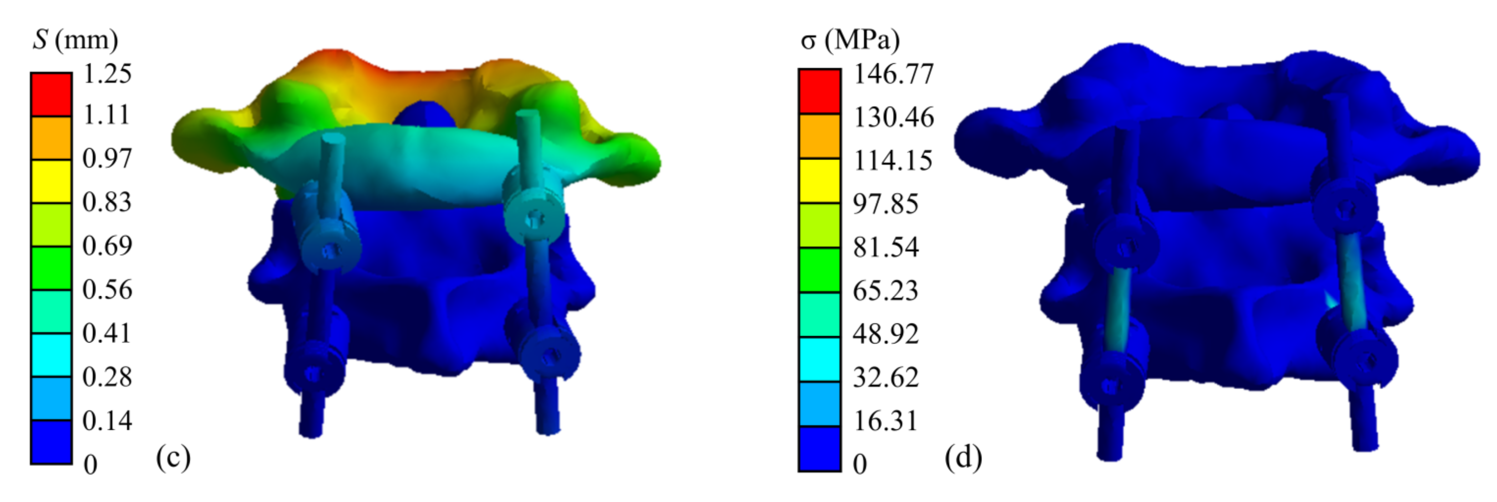
The finite element simulation results of the atlantoaxial fixation system under a 25 N head gravity load are shown in Figure 9. As shown, the maximum displacement of the overall model is 1.25 mm, which occurs at the anterior edge of the atlantoaxial spine. This displacement variation indicates that atlantoaxial fusion preserved some flexion/extension of the neck, which was clinically permitted. The maximum stress on the model was located on the screw at 146.77 MPa, and the maximum stress on the atlantoaxial spine was 57.68 MPa, which is within the yield limit of the human skeleton (121–210 MPa).
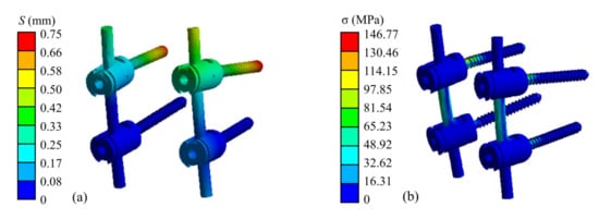
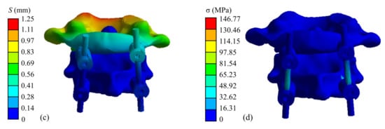
Figure 9.
Simulation results of an atlantoaxial fixation system under head gravity load: (a) Displacement distribution of screw frame; (b) Stress distribution of screw frame; (c) Displacement distribution of atlantoaxial fixation system; (d) Stress distribution of atlantoaxial fixation system.
When the neck was in extension, rotation, and tilting, the maximum stresses on the atlantoaxial fixation system were 64.03 MPa, 151.42 MPa, and 159.49 MPa, respectively. The maximum stresses on the atlantoaxial spine were 54.80 MPa, 79.83 MPa, and 64.89 MPa, respectively. When the neck was in extension, the maximum and minimum axial forces on the four screws were 18.84 N and 10.52 N, respectively; when the neck was in rotation, the maximum and minimum axial forces on the screws were 60.21 N and 41.29 N, respectively; and when the tilt motion was performed, the maximum and minimum axial forces on the screws were 26.69 N and 9.97 N, respectively.
3.2. Mechanical Test before Corrosion
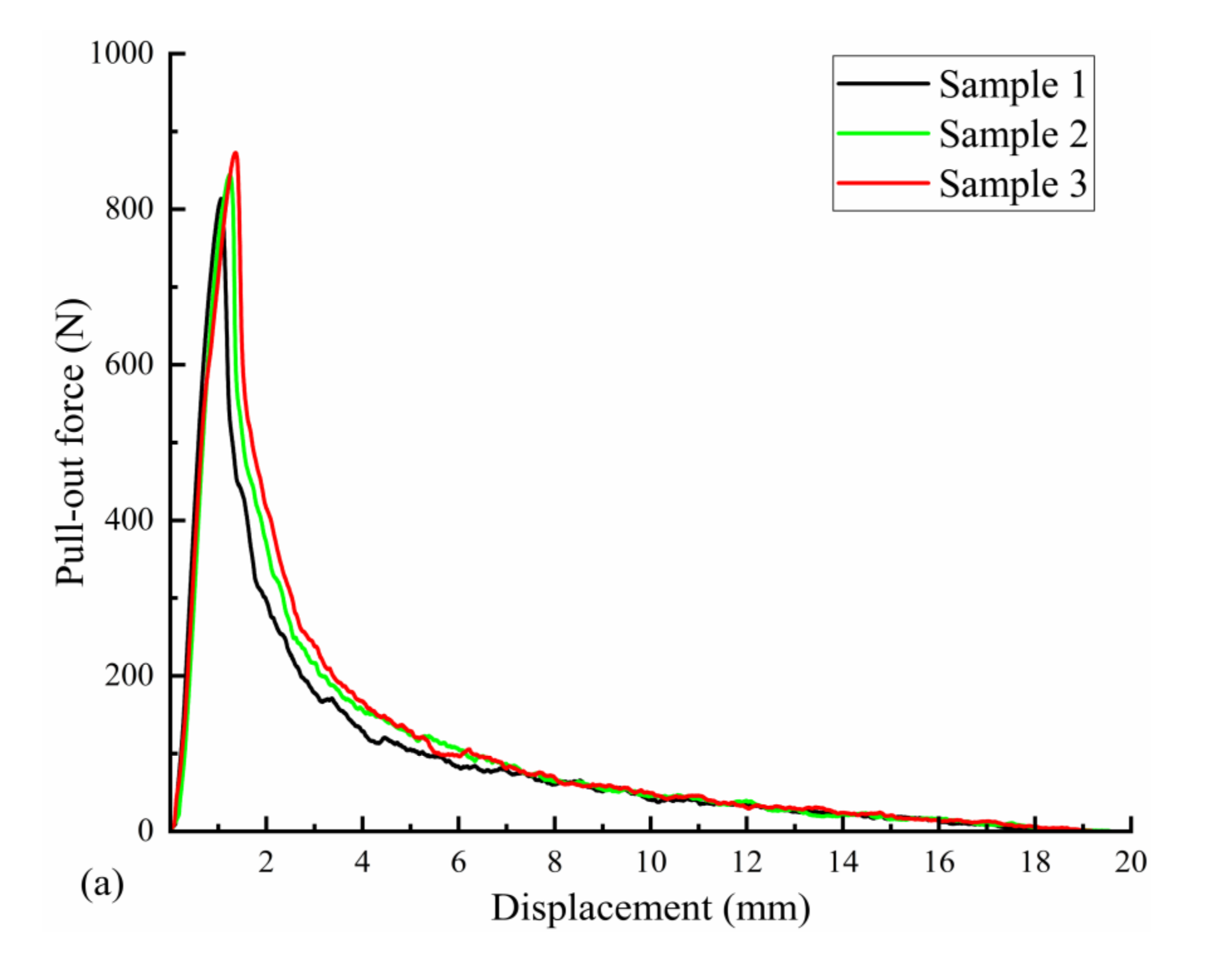
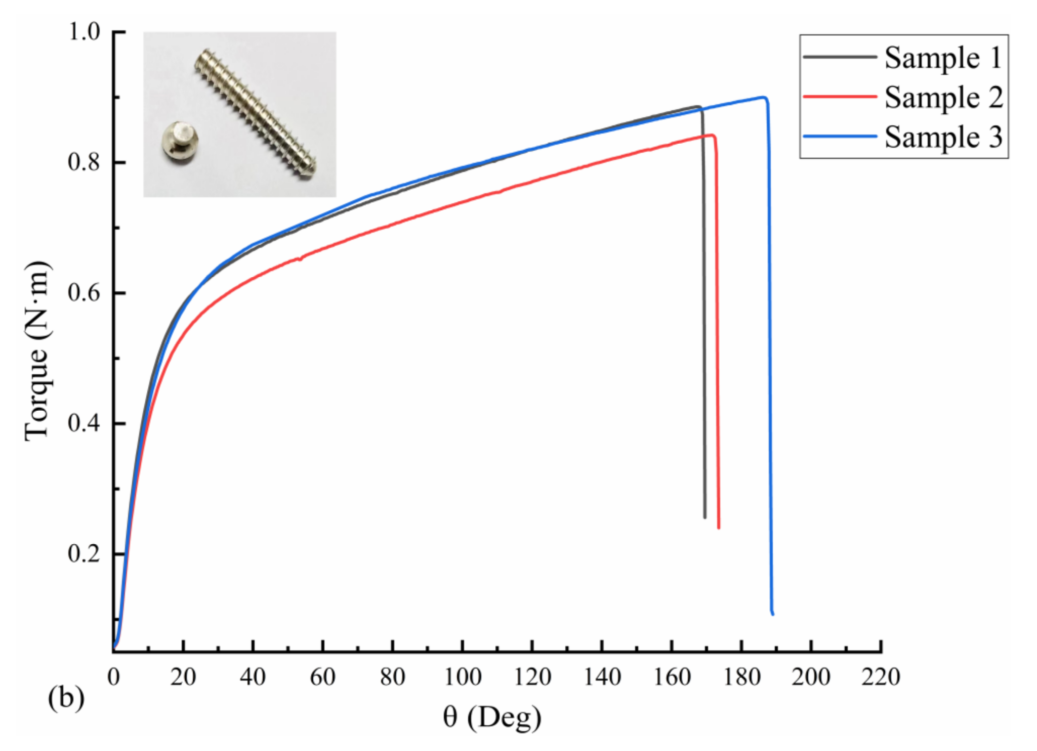
Three uncorroded screws were used for pull-out force and torsion tests. The average torque required to insert the screws into the polyurethane block was 21.72 N·cm, as measured with a torsion tester. The pull-out force test results are shown in Figure 10a; the pull-out force peaked at an average of 843.66 N when the screws were axially displaced by approximately 1.5 mm during the pull-out process. The screws used in the test were completely pulled out, and no fractures occurred. The results of the screw torsional strength tests are shown in Figure 10b. The maximum torque required to break the screws by twisting was 88.56 N·cm on average, and the torsional strength of the screws was 0.26 MPa on average, with an average fracture torsion angle of 174.67°. Figure 10b also shows that the fracture occurred in the area below the head of the screw and before the start of the thread (screw neck).
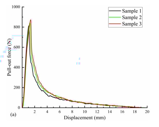
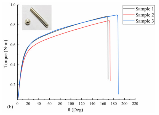
Figure 10.
Mechanical test results of three Mg screw samples: (a) pull-out-force-displacement curve and (b) torque-torsion angle curve.
3.3. Corrosion Test
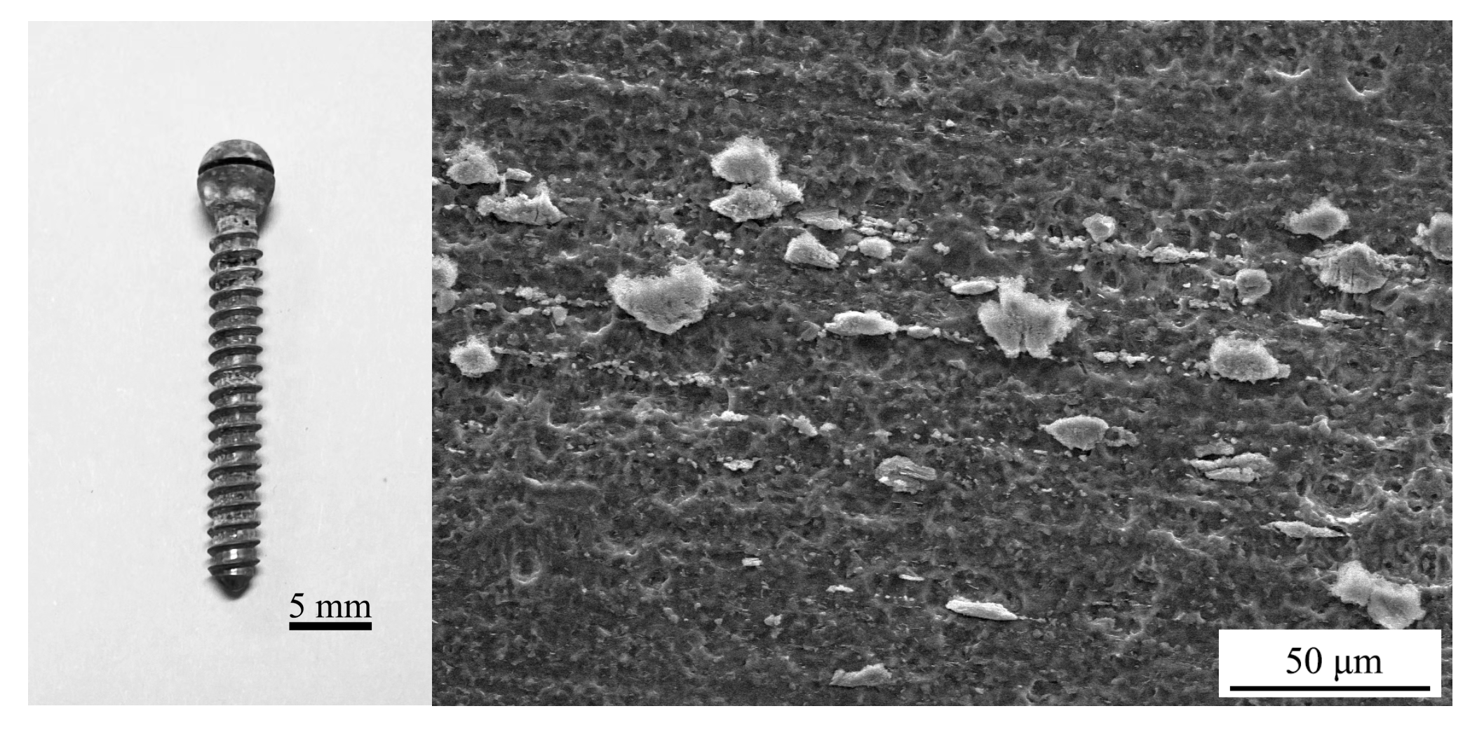
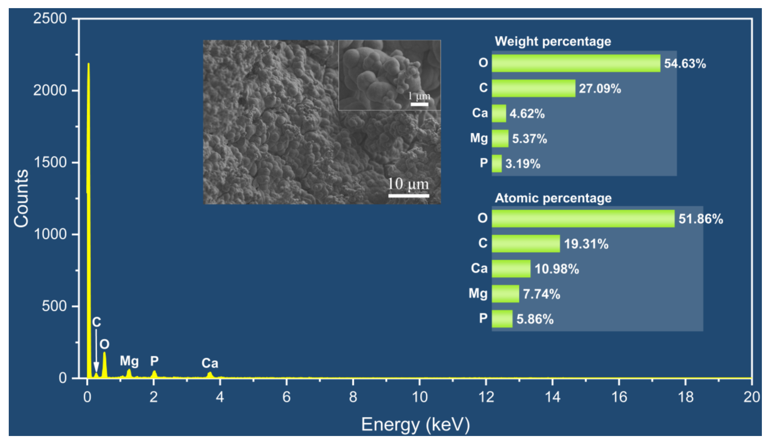
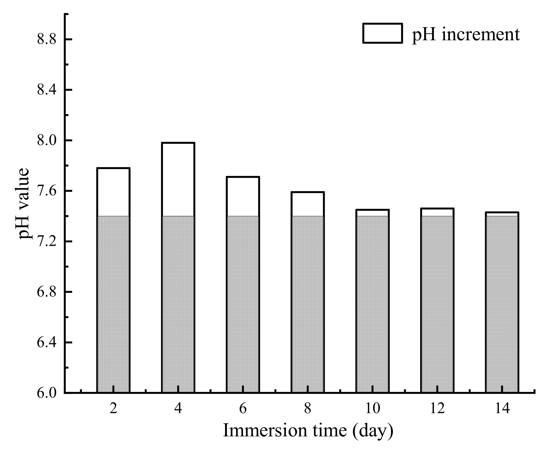
The appearance of the Mg alloy screw after 14 d of corrosion is shown in Figure 11; white insoluble salt corrosion products can be observed on the surface of the sample. The corrosion of the screw neck and the middle part of the thread is more serious, and corrosion traces of different depths can be observed from the SEM image. Figure 12 shows the corrosion products observed from the SEM and their energy spectrum analysis results, which show that the corrosion products accumulated on the surface of the screw in the form of spheres. The energy spectrum analysis revealed that O was the main component of the corrosion products. The average hydrogen generation rate and the mass difference of the specimen before and after immersion are shown in Table 4, and the average corrosion rate of the specimen was 0.46 mg·cm−2·day−1. The degradation of the Mg alloy increased the solution alkalinity, and the pH change pattern is shown in Figure 13. The pH value of the solution increased in the first four solutions, and the increment decreased in the following days and tended to be smooth.

Figure 11.
Appearance of the Mg alloy screw after immersion corrosion.

Figure 12.
SEM-EDS results of corrosion products.
Table 4.
Data related to the immersion corrosion test.

Figure 13.
The pH changes in Hank’s solution during immersion corrosion.
3.4. Mechanical Properties after Corrosion
Mg alloy screws corroded for 14 days were screwed into a polyurethane block for pull-out force testing, and the pull-out force peaked at an average of 880.23 N when the screws produced an axial displacement of approximately 1.56 mm. The results are not significantly different from those obtained before immersion corrosion, and the screws used for testing were all extracted without fractures. When the screws were tested for torsional strength after corrosion, the maximum torque required to twist the screw to fracture was 58.89 N·cm on average, and torsional fracture occurred in the neck and threaded section of the screw with pitting marks.
4. Discussion
Most of the pedicle screws currently used in clinical applications are made of inert metals, which are non-degradable and persist in the body for long periods. This study innovatively investigates the biodegradable Mg alloy pedicle screws for atlantoaxial fixation. As biodegradable biomedical materials, Mg alloys can be used for both engineering and medical purposes owing to their good biocompatibility, but the uncontrollable degradation rate is an important factor limiting their application. The degradation of Mg alloys in a body fluid environment consists of the following stages:
anodic phase: Mg → Mg2+ + 2e−
cathodic phase: 2H2O + 2e− → H2 + 2OH−
Mg2+ + 2OH− → Mg(OH)2
When the Mg alloy is immersed in body fluid, a cathodic reaction occurs immediately, producing H2. When the biological environment is unable to remove excess H2, it gathers in the surrounding tissues and forms gas pockets, resulting in adverse clinical consequences, which can cause gas gangrene in severe cases [10,14,28]. Modulating the degradation process to reduce the rate of H2 production is the primary way to improve the biocompatibility of Mg alloys. During the cathodic reaction, the Mg(OH)2 film covering the implant surface slows down the degradation process of the Mg alloy, which explains the peak gas formation and degradation rate in the initial stage of implantation and subsequent stabilization. The Mg(OH)2 film is mostly loose and has a porous structure, which has a limited protective effect on the Mg alloy. Mg(OH)2 is unstable in body fluids with chloride values above 30 mmol/L [29], which proceeds as follows:
Mg(OH)2 + 2Cl− → MgCl2 + 2OH−
This process results in a highly alkaline and high Mg2+ concentration in the environment surrounding the implant. A highly alkaline and high Mg2+ environment enhances osteoblast activity and decreases osteoclast activity, and the deficiency of Mg in a diet causes a decrease in bone mineral density and an increase in osteoclast activity [30,31,32]. This may account for the positive effects of Mg on biostability, osteogenesis, and anti-inflammation [33].
In this study, the mechanical and degradation properties of Mg alloy screws were investigated. The results of immersion tests for the WE43 Mg alloy pedicle screws revealed that the degradation rate of the screws after polishing treatment was 0.46 mg·cm−2·day−1. The screws maintained good structural integrity within 14 d, and the corrosion rate first showed a fast and then stable pattern, consistent with the results reported by Sabri et al. [34]. After atlantoaxial pedicle screw internal fixation, the screw head is covered by a screw cap and the threaded segment is buried in the bone tissue with little surrounding body fluid environment, which slows down the degradation process of the Mg alloy and prolongs the action time of the screw.
The tensile strength of the WE43 Mg alloy used in this study was 304 MPa and the yield strength was 287.76 MPa. In the simulation analysis of the atlantoaxial fixation system, the maximum stress on the screw was 159.49 MPa when the neck was in the upright state or subjected to extension, rotation, and tilt movements, which was lower than the strength value of the Mg alloy; the maximum axial force on the screw in different movement modes was 60.21 N, and under this axial force, the displacement of the screw was small (approximately 0.24 mm). These results provide theoretical support to prove that the mechanical strength and fixation effect of WE43 Mg alloy pedicle screws satisfy the requirements of atlantoaxial fixation.
Before and after corrosion, the extraction resistance of the Mg alloy screw was 843.66 N and 880.23 N, respectively, and no fracture occurred during extraction; therefore, it can be assumed that the screw will not loosen due to neck movement after completing atlantoaxial fixation. After immersion corrosion, the extraction resistance of the screw increased, probably because corrosion increased the surface roughness of the screw, and the friction between the screw and polyurethane increased, resulting in a more difficult extraction of the screw.
The torsional fracture of Mg alloy screws occurred at the screw neck and pitting of the threaded segment after immersion corrosion occurred, and the torsional strength was reduced compared with that before corrosion, but it was still greater than the torque required to screw the screws into polyurethane (21.72 N·cm). This means that when the screw is subjected to torque after the fixation is completed, it will twist first instead of fracturing. Moreover, after the installation was completed, the screws were subjected to shear and bending loads, and the torsional load on the screws was lower and less prone to torsional fracture.
5. Conclusions
In this study, the finite element analysis of the WE43 Mg alloy pedicle screws and the atlantoaxial fixation system was performed. Results revealed that the triangular thread screw has optimal resistance to extraction. The immersion corrosion and the mechanical test results of the screws before and after corrosion revealed that triangular thread Mg alloy screws are ideal for supporting the neck for different movements, such as upright, extension, torsion, and tilting in atlantoaxial fixation. The corrosion rate of the Mg alloy screw in the body fluid environment is first fast and then slow, and the corrosion products deposited on the surface can have a protective effect on the Mg alloy and prolong the degradation time of the screw. The results of this study provide a basis for using Mg alloy pedicle screws for atlantoaxial fixation. However, the atlantoaxial spine has more freedom of movement under physiological conditions, whereas its stability is supported only by ligaments and the joint capsule. This study failed to simulate the joint action of the muscles, ligaments, and other physiological tissues on the atlantoaxial spine. The in vivo corrosion behavior of Mg alloy pedicle screws and the effect of their corrosion products on atlantoaxial bone tissue should be investigated further.
Supplementary Materials
The following supporting information can be downloaded at: https://www.mdpi.com/article/10.3390/met13020352/s1, Figure S1: Setup of immersion test.
Author Contributions
H.C. conceived this project and worked with Y.Z., X.G. and C.B. to set up the project team. H.C. and Y.Z. carried out structural design, finite element simulation, experiments for mechanical test, microstructure characterizations and degradation measurements. Y.Z. performed experiments and collected the relevant data and analyzed. All the authors contributed to the writing of manuscript. All authors have read and agreed to the published version of the manuscript.
Funding
This research was funded by the Shanghai Municipal Science and Technology Major Project (No. 2021SHZDZX), Shanghai Industrial Collaborative Innovation Project (No. 2021-cyxt1-kj07), Shanghai Science and Technology Innovation Action Plan (No. 22S31902200), and Shanghai Aerospace Science and Technology Innovation Fund (No. SAST2022-094), PR China.
Institutional Review Board Statement
Not applicable.
Informed Consent Statement
Not applicable.
Data Availability Statement
Not applicable.
Conflicts of Interest
The authors declare no conflict of interest.
References
- Dadlani, P.; Baratloo, A. Neck pain and limb weakness: A case of spontaneous atlantoaxial dislocation. Vis. J. Emerg. Med. 2021, 25, 101178. [Google Scholar] [CrossRef]
- Liawrungrueang, W.; Laohapoonrungsee, A.; Bunmaprasert, T. Acute traumatic lateral atlantoaxial dislocation associated with locked atlas lateral mass and odontoid process fracture: A clinical case study and literature review. N. Am. Spine Soc. J. 2022, 12, 100169. [Google Scholar] [CrossRef] [PubMed]
- Chatterjee, S. Atlantoaxial Rotatory Subluxations in Children: A Review. Spine J. 2015, 15, S239. [Google Scholar] [CrossRef]
- Juneja, M.; Sharma, S.; Jain, R. Atlantoaxial dislocation in a child with generalized primary dystonia. J. Clin. Neurosci. 2011, 18, 966–968. [Google Scholar] [CrossRef]
- Goel, A.; Dhar, A.; Shah, A. Central or Axial Atlantoaxial Dislocation as a Cause of Cervical Myelopathy: A Report of Outcome of 5 Cases Treated by Atlantoaxial Stabilization. World Neurosurg. 2019, 121, e908–e916. [Google Scholar] [CrossRef] [PubMed]
- Tan, M.; Wang, H.; Wang, Y. Morphometric Evaluation of Screw Fixation in Atlas via Posterior Arch and Lateral Mass. Spine 2003, 28, 888–895. [Google Scholar] [CrossRef]
- Zhai, M.Y.; Wang, C.P.; Liu, F. The efficacy of pedicle screw instrument in treatment of irreducible atlantoaxial dislocation. Arch. Orthop. Trauma Surg. 2015, 135, 1193–1199. [Google Scholar] [CrossRef]
- Guo, Q.; Zhou, X.; Guo, X. C2 partial transpedicular screw technique for atlantoaxial dislocation with high-riding vertebral artery: A technique note with case series. Clin. Neurol. Neurosurg. 2021, 200, 106403. [Google Scholar] [CrossRef] [PubMed]
- Radha, R.; Sreekanth, D. Insight of magnesium alloys and composites for orthopedic implant applications—A review. J. Magnes. Alloy 2017, 5, 286–312. [Google Scholar] [CrossRef]
- Schaller, B.; Saulacic, N.; Imwinkelried, T. In vivo degradation of magnesium plate/screw osteosynthesis implant systems: Soft and hard tissue response in a calvarial model in miniature pigs. J. Craniomaxillofac. Surg. 2016, 44, 309–317. [Google Scholar] [CrossRef]
- Zreiqat, H.; Howlett, C.; Zannettino, A. Mechanisms of magnesium-stimulated adhesion ofosteoblastic cells to commonly used orthopaedic implants. J. Biomed. Mater. Res. A 2010, 62, 175–184. [Google Scholar] [CrossRef] [PubMed]
- Zai, W.; Zhang, X.; Su, Y. Comparison of corrosion resistance and biocompatibility of magnesium phosphate (MgP), zinc phosphate (ZnP) and calcium phosphate (CaP) conversion coatings on Mg alloy. Surf. Coat. Technol. 2020, 397, 125919. [Google Scholar] [CrossRef]
- Wang, H.; Shi, Z. In vitro biodegradation behavior of magnesium and magnesium alloy. J. Biomed. Mater. Res. B Appl. Biomater. 2011, 98, 203–209. [Google Scholar] [CrossRef] [PubMed]
- Zhao, D.; Wang, T.; Kuhlmann, J. In vivo monitoring the biodegradation of magnesium alloys with an electrochemical H2 sensor. Acta Biomater. 2016, 36, 361–368. [Google Scholar] [CrossRef]
- Kaesel, V.; Tai, P.T.; Bach, F.W. Approach to Control the Corrosion of Magnesium by Alloying. In Magnesium: Proceedings of the 6th International Conference Magnesium Alloys and Their Applications; Wiley-VCH Verlag GmbH & Co. KGaA: Weinheim, Germany, 2005; p. 534. [Google Scholar] [CrossRef]
- Xu, R.; Wu, G.; Yang, X. Controllable degradation of biomedical magnesium by chromium and oxygen dual ion implantation. Mater. Lett. 2011, 65, 2171–2173. [Google Scholar] [CrossRef]
- Witte, F.; Kaese, V.; Haferkamp, H. In vivo corrosion of four magnesium alloys and the associated bone response. Biomaterials 2005, 26, 3557–3563. [Google Scholar] [CrossRef]
- Song, G. Recent Progress in Corrosion and Protection of Magnesium Alloys. Adv. Eng. Mater. 2005, 7, 563–586. [Google Scholar] [CrossRef]
- Jin, Y.; Blawert, C.; Yang, H. Microstructure-corrosion behaviour relationship of micro-alloyed Mg-0.5Zn alloy with the addition of Ca, Sr, Ag, In and Cu. Mater. Des. 2020, 195, 108980. [Google Scholar] [CrossRef]
- Saberi, A.; Bakhsheshi-Rad, H.R.; Ismail, A.F. The Effect of Co-Encapsulated GO-Cu Nanofillers on Mechanical Properties, Cell Response, and Antibacterial Activities of Mg-Zn Composite. Metals 2022, 12, 207. [Google Scholar] [CrossRef]
- Al-Buainain, M.; Shunmugasamy, V.C.; Usman, C.A. Influence of Microstructure on the Mechanical and Corrosion Response of a Friction Stir-Extruded WE43 Magnesium Rod. Metals 2023, 13, 191. [Google Scholar] [CrossRef]
- Liu, J.; Yin, B.; Song, F. Improving corrosion resistance of additively manufactured WE43 magnesium alloy by high temperature oxidation for biodegradable applications. J. Magnes. Alloy, 2022; in press. [Google Scholar] [CrossRef]
- Jo, J.H.; Kang, B.G.; Shin, K.S. Hydroxyapatite coating on magnesium with MgF(2) interlayer for enhanced corrosion resistance and biocompatibility. J. Mater. Sci. Mater. Med. 2011, 22, 2437–2447. [Google Scholar] [CrossRef] [PubMed]
- Sun, Z.; Wang, Z.; Guan, S. Degradation of Mg-Zn-Y-Nd alloy intestinal stent and its effect on the growth of intestinal endothelial tissue in rabbit model. J. Magnes. Alloy 2022, 10, 2208–2219. [Google Scholar] [CrossRef]
- Lü, Z.; Zhou, J.; Sun, Z.M. Effect of rare earth elements on the structures and mechanical properties of magnesium alloys. Chin. Sci. Bull. 2013, 58, 816–820. [Google Scholar] [CrossRef]
- Gusieva, K.; Davies, C.; Scully, J. Corrosion of magnesium alloys: The role of alloying. Int. Mater. Rev. 2014, 60, 169–194. [Google Scholar] [CrossRef]
- Zhang, X.; Gao, K.; Xie, H. Characteristics of Cervical Sagittal Alignment at Different C0-C2 Correcting Angles in Fusion Treatment of Atlantoaxial Dislocations. World Neurosurg. 2019, 124, e119–e124. [Google Scholar] [CrossRef]
- Chaya, A.; Yoshizawa, S.; Verdelis, K. In vivo study of magnesium plate and screw degradation and bone fracture healing. Acta Biomater. 2015, 18, 262–269. [Google Scholar] [CrossRef]
- Janning, C.; Willbold, E.; Vogt, C. Magnesium hydroxide temporarily enhancing osteoblast activity and decreasing the osteoclast number in peri-implant bone remodelling. Acta Biomater. 2010, 6, 1861–1868. [Google Scholar] [CrossRef]
- Bushinsky, A.D. Metabolic alkalosis decreases bone calcium efflux by suppressing osteoclasts and stimulating osteoblasts. Am. J. Physiol. 1996, 1, 216–222. [Google Scholar] [CrossRef]
- Rude, R.K.; Gruber, H.E.; Wei, L.Y. Magnesium deficiency: Effect on bone and mineral metabolism in the mouse. Calcif. Tissue Int. 2003, 72, 32–41. [Google Scholar] [CrossRef]
- Rude, R.K.; Gruber, H.E.; Norton, H.J. Reduction of dietary magnesium by only 50% in the rat disrupts bone and mineral metabolism. Osteoporos. Int. 2006, 17, 1022–1032. [Google Scholar] [CrossRef] [PubMed]
- Li, Y.; Liu, G.; Zhai, Z. Antibacterial properties of magnesium in vitro and in an in vivo model of implant-associated methicillin-resistant Staphylococcus aureus infection. Antimicrob. Agents Chemother. 2014, 58, 7586–7591. [Google Scholar] [CrossRef] [PubMed]
- Shafyra, S.; Nazim, E.M.; Ngadiman, N.H.A. Comparative Study on the Microstructure and Biodegradation Behavior of Commercialized Pure Mg and Mg-1.0Ca-0.5Sr Alloy in 27 mM HCO3−-SBF: The Influence of the pH Regulation Treatments. Metals 2023, 13, 136. [Google Scholar] [CrossRef]


Disclaimer/Publisher’s Note: The statements, opinions and data contained in all publications are solely those of the individual author(s) and contributor(s) and not of MDPI and/or the editor(s). MDPI and/or the editor(s) disclaim responsibility for any injury to people or property resulting from any ideas, methods, instructions or products referred to in the content. |
© 2023 by the authors. Licensee MDPI, Basel, Switzerland. This article is an open access article distributed under the terms and conditions of the Creative Commons Attribution (CC BY) license (https://creativecommons.org/licenses/by/4.0/).