Article

Reduction Kinetics of Pre-Oxidized Ilmenite Pellets by H2-H2O Gas Mixtures

SINTEF, NO-7034 Trondheim, Norway
*
Author to whom correspondence should be addressed.
Metals 2023, 13(2), 332; https://doi.org/10.3390/met13020332
Submission received: 29 November 2022 / Revised: 15 January 2023 / Accepted: 31 January 2023 / Published: 7 February 2023
(This article belongs to the Special Issue Hydrogen Based Direct Reduction of Metals Oxides)

Abstract

:
The reduction behavior of pelletized and pre-oxidized ilmenite is investigated in H2-H2O atmospheres containing between 0 and 7% H2O and at temperatures between 983 and 1183 K (710 and 910 °C). The reduction mechanism occurs in two stages wherein the rapid reduction of trivalent to divalent iron cations is followed by the slower metallization of iron. Both temperature and gas composition are critical to achieving high reaction rates; within the range of conditions studied, the driving force for metallization has a significant effect on the reduction rate. Based on the experimental data and thermodynamic calculations, a model is established to predict the progress of the reduction as a function of temperature, gas composition and time. The application of this model at variable temperatures permits the determination of the activation energy Ea = 51 kJ/mol for the metallization reaction.

1. Introduction

The imperative diminution of CO2 emissions has led to new research on processes using hydrogen as a reductant. Among the metallurgical industries, ironmaking and steelmaking have been particularly active in pursuing hydrogen-based direct reduction, and the industrialization of this process is becoming increasingly likely [1,2,3]. While green hydrogen production and storage is a challenge in itself [3,4], reduction reactions also need to be optimized to limit hydrogen consumption; this is an active research domain [5,6,7].
Although not yet undertaken industrially, the closely related topic of ilmenite reduction by hydrogen is also very promising; development is well underway at TiZir Titanium and Iron (now known as Eramet Titanium and Iron) in Tyssedal, Norway. The project to replace coal with hydrogen in their pre-reduction unit has recently been approved as an “important project of common European interest” (IPCEI) for hydrogen [8].
The reduction of ilmenite by hydrogen has been studied in several contexts over the past decades. Ilmenite is viewed as a potential source of oxygen in lunar materials [9,10] but also and most importantly as a source of TiO2 for pigment production and of pig iron for foundry products. Although the processes studied here are often named “ilmenite reduction”, the pre-oxidation of ilmenite (to pseudobrookite at T > 1073 K (800 °C)) has been found to be beneficial to the overall reduction [11,12,13]; pre-oxidation was shown to increase the reducibility and the reduction rate. The study of ilmenite reduction therefore generally comprises the reduction of various mineral forms taken by iron titanium oxides. Various samples’ physical forms have been studied; the reduction of disks [9,10], pellets [14,15,16,17] and powders [11,16,18,19,20,21,22] of various sizes has been investigated. Most experiments found in the literature were carried out isothermally [9,10,11,15,16,17,18,19,20,21], but non-isothermal experiments were also performed to identify the reaction temperature [20].
Water vapor, which is a direct product of oxide reduction by hydrogen gas, can quickly inhibit the reaction by reducing the driving force for the metallization of iron. The industrialization of the hydrogen-based reduction of iron titanium oxides will undoubtedly raise the question of gas purity and its influence on reaction kinetics, as processes are optimized based on temperature, reaction duration and gas purity. The present work proposes to deal with this challenge by investigating the reduction of pre-oxidized ilmenite pellets at various temperatures and levels of water vapor content.

2. Materials and Methods

2.1. Sample Preparation and Isothermal Reduction

The samples investigated in this work were pelletized and pre-oxidized ilmenite powders of natural origin supplied by TiZir. Analysis, pelletization and pre-oxidation were carried out by Minpro AB [23] to produce pellets of 10–14 mm. Concerning the particle size, 74.1% of the powder was below 45 µm. The specific surface area, measured via Blaine test, was reported equal to 2430 cm2/g and the porosity reported by Minpro was 27.1%. Pelletization was carried out with 0.8 wt% bentonite addition and pre-oxidation was performed in a pot grate at 1223 K (950 °C). Sample composition, analyzed after pre-oxidation, is given in Table 1; most oxides were determined through X-ray fluorescence (XRF), while FeO was determined through wet chemistry techniques. The Fe2O3 content was back-calculated from the results of the two previous analyses. It is considered to be mostly a mixture of pseudobrookite and rutile formed upon oxidation of ilmenite following the reaction given in Equation (1):
2FeTiO3 + 0.5O2(g) = Fe2TiO5 + TiO2
The X-ray diffraction (XRD) spectrum of the raw materials is given in Figure 1 below. Both hematite and pseudobrookite peaks were identified in addition to rutile and ilmenite. Rietveld-type fitting was performed in order to estimate the relative amount of trivalent to divalent iron cations. The results show that ilmenite was largely pre-oxidized, giving an Fe3+:Fe2+ ratio of 24. In this work, the values used in Table 1 are considered more correct than the Rietveld estimates.
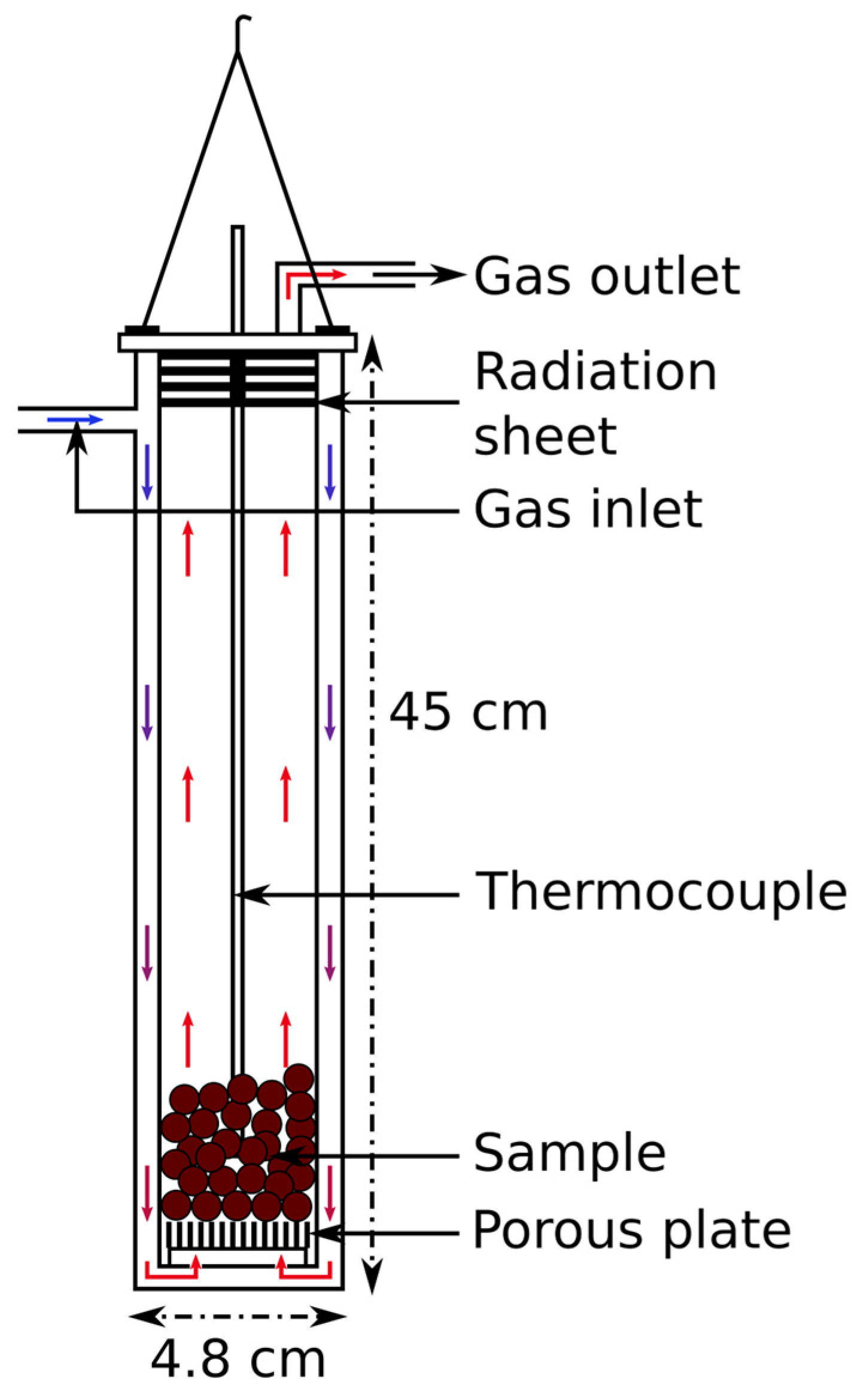
The pre-oxidized ilmenite pellets were loaded in a steel crucible and then reduced by H2-H2O gas mixtures in a vertical retort thermogravimetric setup; a schematic is given in Figure 2. The gas was introduced at the top of the double-walled crucible and was heated up on its way to the sample between the two walls. When reaching the bottom of the crucible, the gas entered the reaction chamber from the bottom. It passed through a porous alumina plate, itself resting on a steel platform; this ensured a good distribution of the gas flow through the charge. An alumina sheath containing an S-type thermocouple measuring the “crucible temperature”, i.e., the temperature inside the crucible, was inserted down to the middle of the pellet charge. The crucible was suspended from a weight balance (Mettler Toledo PR2003DR) measuring and recording the weight changes. During operation, high-purity argon gas (99.999%) and industrial-grade hydrogen (99.5%) were used. The water vapor was added to the hydrogen mixture using an evaporative mixer. The temperature and gas composition during the experiment were controlled by a computer. The temperature ramp-up was performed at a rate of 10 °C/min under 1 L/min of argon. Upon reaching the targeted temperature, the argon flow was increased to 8 L/min for 15 min. Then, the reducing gas mixture was introduced with composition and flow corresponding to the intended experimental conditions. Upon cooling, after the isothermal reduction stage, the process gas was replaced by argon at a flow of 4 L/min for 10 min to flush out the remaining reducing gases. The flow was then lowered to 1 L/min for the rest of the cooling period.
Ten isothermal reduction experiments were performed at various temperatures and water vapor content levels in the gas mixtures. The details of the experimental conditions can be found in Table 2. Experiments n°8 and n°9 were carried out with a flow below the 8 L/min used as a standard in the other experiments.

2.2. Sample Analysis

For each experiment, several pellets were embedded in epoxy and polished with a diamond solution. Prior to analysis, a carbon coating of 150 Å was deposited on the samples. The reacted samples were analyzed by an electron microprobe (EPMA; JEOL; JXA-8500F) equipped with a wavelength-dispersive x-ray spectroscope using 15 kV acceleration voltage and a 20 nA beam current.
For some experiments, as well as for the raw materials, XRD analysis was performed using a D8 Advance X-ray powder diffractometer operating in Bragg–Brentano mode with a Cu-Kα radiation source. Bruker DIFFRAC.EVA software was used together with the ICDD PDF4+ 2022 database to identify phases. In addition, Rietveld refinement was performed using Bruker Topas v5 software.

2.3. Reactions and Kinetic Modeling

The reduction path, starting from pre-oxidized ilmenite, is considered to proceed via the reactions given in Equations (2) and (3) below. In Equation (2), pseudobrookite and titanium dioxide reform ilmenite; this corresponds to a reduction of two trivalent iron cations down to divalent state. Then, through Equation (3), ilmenite is reduced to metallic iron and titanium dioxide; the divalent iron cation is thus reduced to metallic state. Starting from a pseudobrookite and titanium dioxide mixture in a 1:1 ratio, one third of the oxygen is extracted through Equation (2), and two thirds are extracted through Equation (3).
Fe2TiO5 + TiO2 + H2(g) = 2FeTiO3 + H2O(g)
FeTiO3 + H2(g) = Fe + TiO2 + H2O(g)
Looking individually at those reactions involving gas–solid reduction of pure oxides to other pure substances, the rate of iron reduction can be written as follows [24]:
R i = k i p H 2 k ii p H 2 O
In Equation (4), i = 1 for the pseudobrookite reduction to ilmenite and i = 2 for the reduction of ilmenite to iron; ki and kii are the apparent chemical rate constants for forward and reverse reactions. In addition, p* corresponds to the partial pressure of the gas species H2 and H2O. Considering a total pressure of 1 atm, the formula is rewritten for convenience as in Equation (5) where pa now refers to the mole fraction of “a” in the gas phase and is now dimensionless. R1 and R2 correspond to the rate reduction of the iron ions in the reactions of Equations (2) and (3).
R i = k i p H 2 k ii p H 2 O
At equilibrium:
0 = k i p H 2 k ii p H 2 O
Thus:
R i = k i p H 2 1 p H 2 p H 2 O eq , i p H 2 O p H 2
In the present case,
p H 2 + p H 2 O = 1
With the following notation:
p H 2 = a ;   p H 2 , eq = a
We have:
p H 2 1 p H 2 p H 2 O eq , i p H 2 O p H 2 = a 1 a 1 a 1 a a = a a 1 a 1 a = a 1 a a 1 a 1 a = a a a a + a a 1 a = p H 2 p H 2 , eq p H 2 O , eq
The reaction rates can be rewritten as follows:
R i = k i p H 2 p H 2 , eq p H 2 O , eq
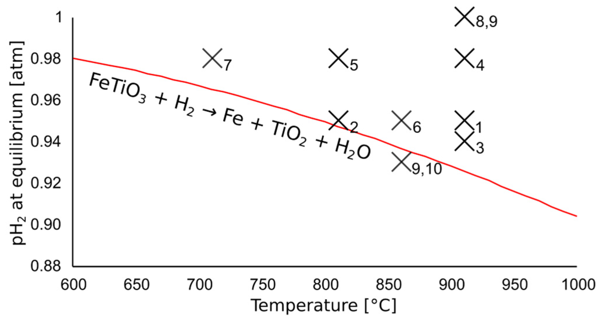
FactSage 8.0 was used to calculate the equilibrium partial pressure of hydrogen for the reduction reactions given in Equations (2) and (3) [25]. The two reactions require contrasting equilibrium partial pressures of hydrogen, the balance being water vapor. The equilibrium partial pressure for the metallization reaction (Equation (3)) is shown in Figure 3 with a red line. If, for an experiment, the temperature and incoming hydrogen content were placed below the red line, the metallization reaction was not expected to occur.
For pseudobrookite reduction to ilmenite, calculations using FactSage 8.0show that the equilibrium partial pressure of hydrogen was very low at any of the temperatures considered in this study: in the order of magnitude of 10−4 atm. In addition, experimentally, the hydrogen partial pressure in the incoming reacting gas was kept close to 1. Consequently, the dependence of the pseudobrookite reduction rate on the gas pressure was ignored for simplicity. Thus, R1 is approximated as follows:
R 1 k 1 p H 2 k 1
For the ilmenite reduction, however, the equilibrium partial pressure of hydrogen was much higher and closer to the pressures involved, and therefore the reaction rate could not be simplified as it was previously. The equilibrium values in Equation (13) correspond to that of ilmenite reduction.
R 2 = k 2 p H 2 p H 2 , eq p H 2 O , eq
The reduction rates were then related to the quantity of iron atoms in their respective valence state in the following way:
d [ Fe 3 + ] dt = R 1 · [ Fe 3 + ]
d [ Fe 2 + ] dt = R 1 · [ Fe 3 + ]     R 2 · [ Fe 2 + ]
d [ Fe ] dt = + R 2 · [ Fe 2 + ]
Finally, the Arrhenius equation was used to describe the temperature dependence of k1 and k2, as shown in Equations (17) and (18), where Ea1 and Ea2 are apparent activation energies for the two reactions studied.
k 1 T = k 0 , 1 · exp E a 1 8 . 31 · T
k 2 T = k 0 , 2 · exp E a 2 8 . 31 · T
The solutions to the differential equations were found using python and the SciPy module [26].

3. Results and Discussion

3.1. Reduction Degree as a Function of Time

The reduction degree was calculated based on the mass loss recordings for each experiment. A reduction degree of 100% corresponds to the full reduction and metallization of iron without any reduction of titanium oxide, although it is known that some reduction may occur when using pure hydrogen gas. Based on the analysis of the pellets given in Table 1, the reduction degree was calculated according to Equation (19):
Reduction   degree   ( % ) = 100 · Δ m m sample · w in   iron   oxides O
The reduction degree corresponds to the mass change upon reduction ∆m divided by the sample mass msample itself multiplied by the mass fraction of oxygen bound to iron w in   iron   oxides O . From the mass measurements recorded during reduction, the reduction degree can be plotted as a function of time for all ten experiments of the study. This is shown in Figure 4. Note that the experiment carried out with pure hydrogen exhibited a reduction degree over 100%. This may have been due to some titanium oxide reduction, as this was shown to occur for pure hydrogen gas [9], but other factors are also considered; they are detailed in the next section of this paper. Because of the presence of H2O in the other experiments, TiO2 reduction was avoided. This is explained by the high equilibrium partial pressure of hydrogen for the reduction of TiO2 to lower the Magnéli phases.
Figure 4 shows that after a quick start, corresponding to the straightforward reduction of pseudobrookite according to Equation (2), both temperature and water vapor content dictated the reduction rates; this was mainly because of the driving force as expressed in Equation (13). Because the equilibrium partial pressure of the hydrogen of the metallization reaction (Equation (3)) is high, a slight change in the gas purity has a large effect on the rate. Similarly, if the temperature is varied, the resulting change of the equilibrium partial pressure affects the driving force, and thus, the reduction rate.
The bottom curve of Figure 4 shows the reduction degree for an experiment where the gas and temperature conditions led to a negative driving force. The metallization reaction was not possible; the reduction degree curve stagnated after the reduction of pseudobrookite was complete. The sudden jump observed after 120 min resulted from the disturbance of the experimental set-up. Yet even before the jump, the plateau value of the reduction degree calculated from mass loss measurements appeared to be higher than the expected value corresponding to the reduction of pseudobrookite; a reduction degree of about 38% was observed while one of about 33% was expected. This also occurred in the other experiments; the quick reduction occurring when introducing the H2-H2O gas mixture seems to continue slightly over what is expected by pseudobrookite reduction. The possible causes for this discrepancy are discussed in the next section of this paper.

3.2. Uncertainties in the Mass Loss Measurements

As observed in Figure 4, there is a significant and consistent mismatch between the reduction degree calculated during the first minutes of reaction and what could be expected by the reduction of pseudobrookite. In this section, two possible explanations for this phenomenon are discussed, assuming that it is not related to a chemical reaction.
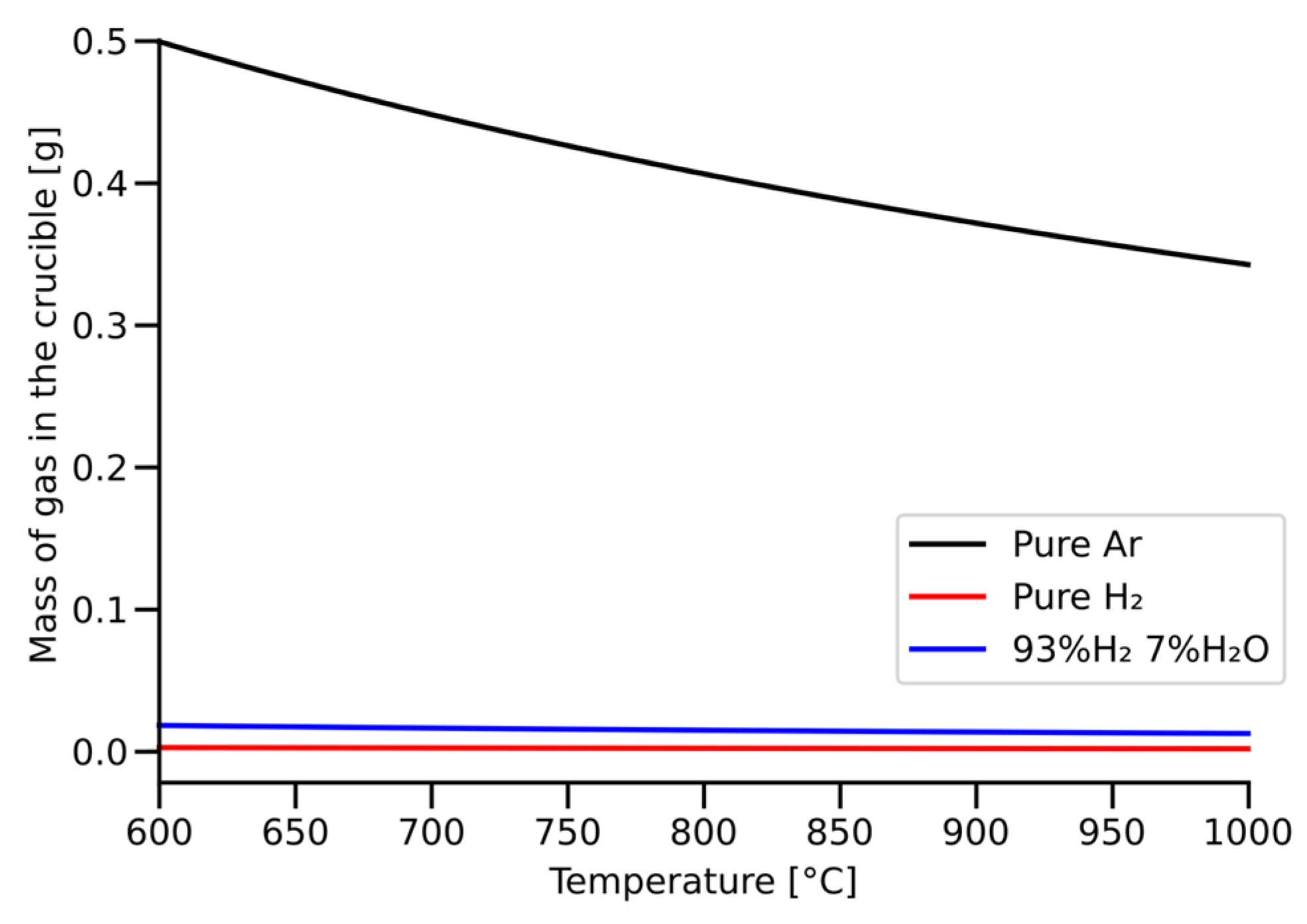
First, the mismatch observed in the reduction degree curve could be partly related to the weight of the gas atmosphere. The change of the gas atmosphere in the crucible has a non-negligible effect on the mass measurement; the replacement of argon (MAr = 39.948 g/mol) by lighter molecules of H2 or H2O (MH2 = 2.016 g/mol, MH2O = 18.015 g/mol) reduces the total mass of gas, thus causing a mass loss in the crucible. Based on the volume of the crucible estimated equal to V = 0.895·10−3 m3 [27], one can deduce the mass of gas as a function of temperature. This is shown in Figure 5. Assuming 0.4 g of mass loss due to the introduction of the process gas instead of argon, the phenomenon can cause an artificial increase of 1.5% to the reduction degree after conversion.
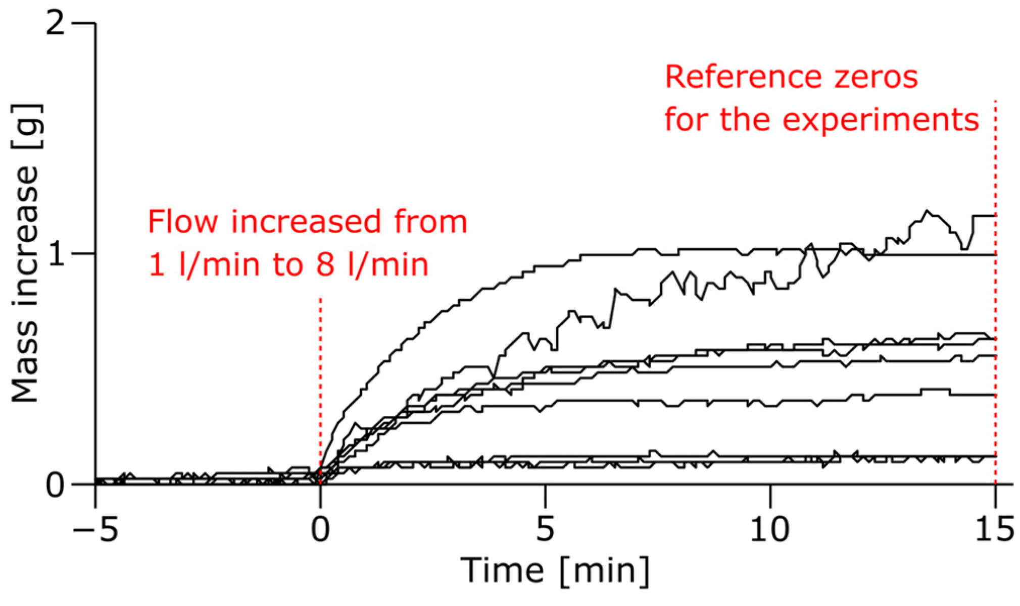
In addition to the nature of the gas atmosphere in the crucible, the gas flow also caused variations in the mass measurements. This was observed when increasing the argon flow from 1 L/min to 8 L/min and keeping the temperature and gas density equal. The corresponding mass increase measured is presented in Figure 6; significant mass changes were observed, being up to approximately 1 g. Converted to the degree of reduction, this would appear as a change of approximately 4%.
Due to the fast reactions occurring upon the introduction of the process gas, it was not possible from the present experiments to distinguish the contribution of gas and flow change to that of the reduction reactions. Nevertheless, the combined contributions of the two phenomena (weight and flow of the gas) on the weighting scale are considered to explain the difference between the measured and expected reduction degree in experiment 10 for which the metallization reaction was avoided.

3.3. Reoxidation of Iron by Water Vapor

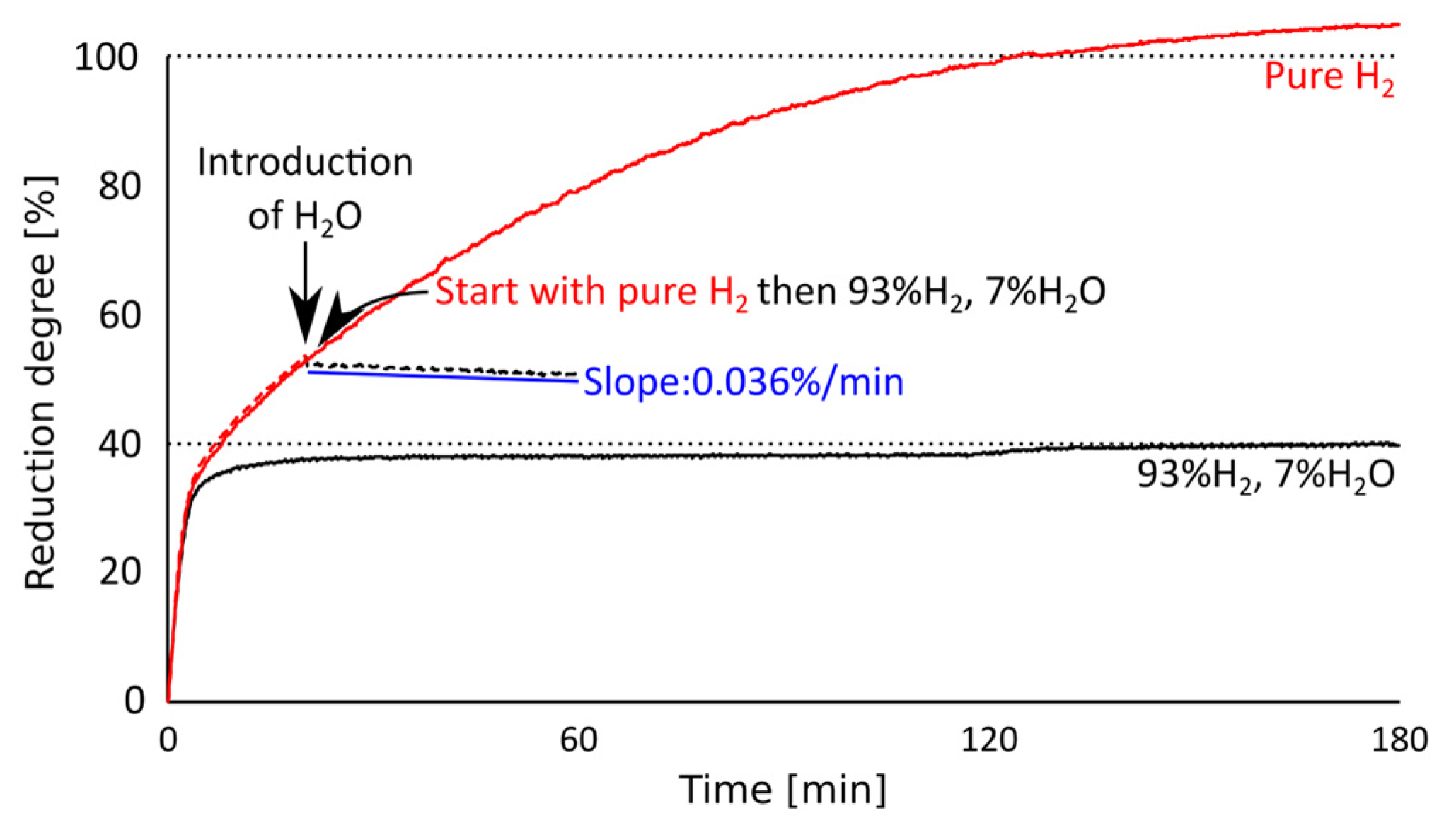
The experimental conditions of experiments 8, 9 and 10 made it possible to observe the occurrence of iron reoxidation. Experiment 10, shown with a black line in Figure 7, was carried out at conditions under which the metallization of iron is not thermodynamically possible. According to our expectations, the reduction degree was quickly capped when all the trivalent iron was reduced to the divalent state. Experiment 8, shown with a red line in Figure 7, was carried out with pure hydrogen for its whole duration. The pure H2 flow used corresponded to the amount of hydrogen contained in the flow of experiment 10, i.e., 7.44 L/min, in order to obtain similar rates for the first reduction stage. Experiment 9, shown with a dotted line, was carried out with the same experimental conditions as experiment 8 until about a 50% reduction degree was reached: at this stage, the first reaction was complete, and some metallization had occurred. Then, water vapor was added to the gas mixture to reach the conditions of experiment 10.
After the introduction of water vapor to the gas mixture, a gradual decrease in the reduction degree was observed. This corresponds to a mass intake, which can only be attributed to reoxidation by water vapor. Because the new gas mixture remained reductive for trivalent to divalent iron reduction, the gradual mass increase must have been due to the reoxidation of metallized iron, as was predicted by thermodynamic equilibrium calculations. These results show the risks of iron reoxidation when using hydrogen as a reductant: If an exhausted gas rich in water vapor comes in contact with reduced material in cooler regions of a furnace, then iron can readily oxidize to a divalent state.

3.4. XRD Analysis

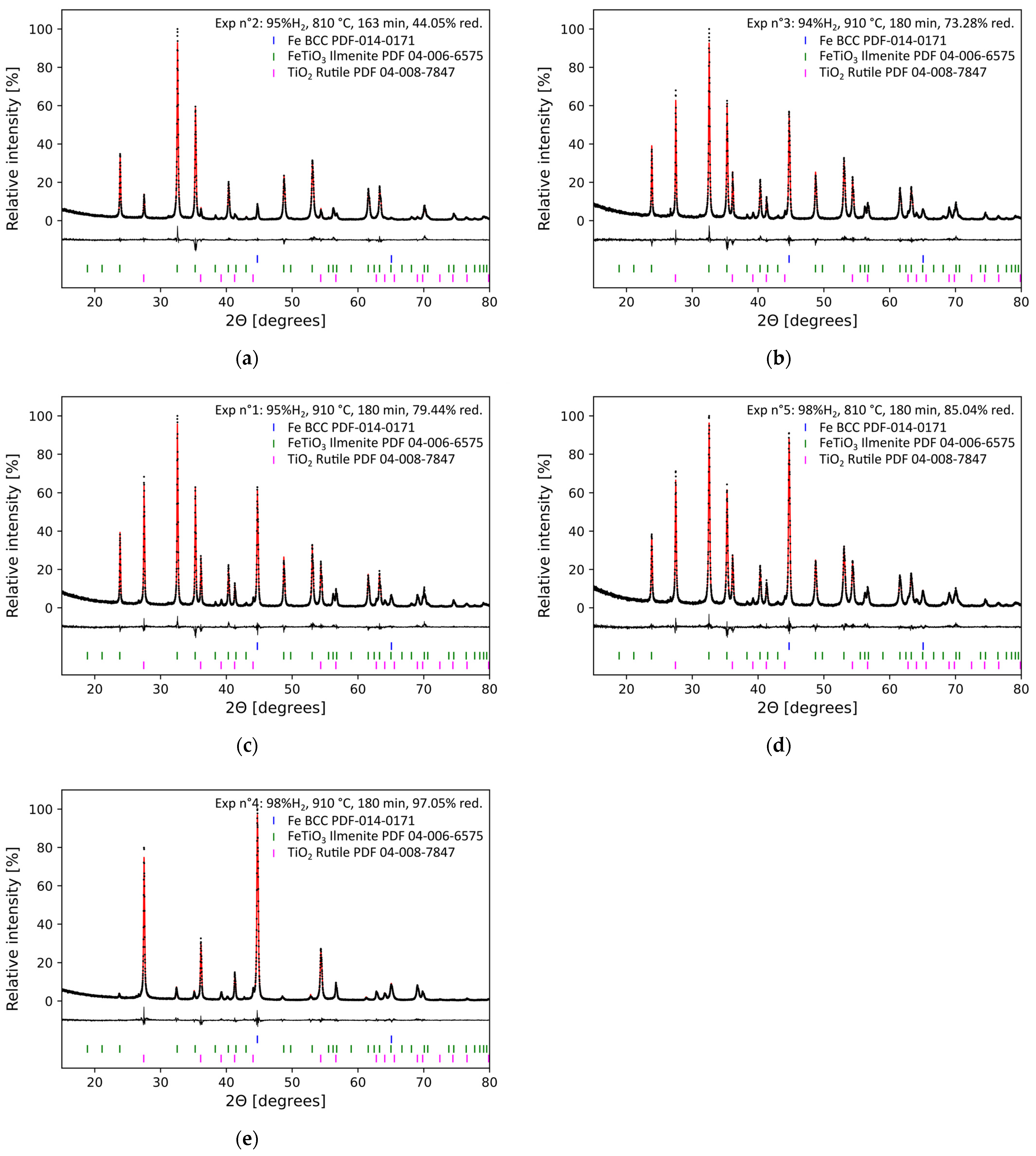
Experiments 1–5 were analyzed by x-ray diffraction. Figure 8 shows the resulting diffraction patterns for each experiment. In addition to quartz, a contamination likely added during milling, only three phases were identified: iron, ilmenite and rutile. In the figure, the pattern of the least reduced sample is placed on the top; the other patterns are placed in order of increasing reduction degree. While ilmenite, rutile and iron were each observed in all the experiments, the ilmenite peaks progressively declined to the benefit of rutile and iron. Pseudobrookite could not be seen in the XRD patterns; this was expected as the trivalent to divalent iron reduction was rapidly completed under the conditions of this study.

3.5. Electron Probe Microanalysis

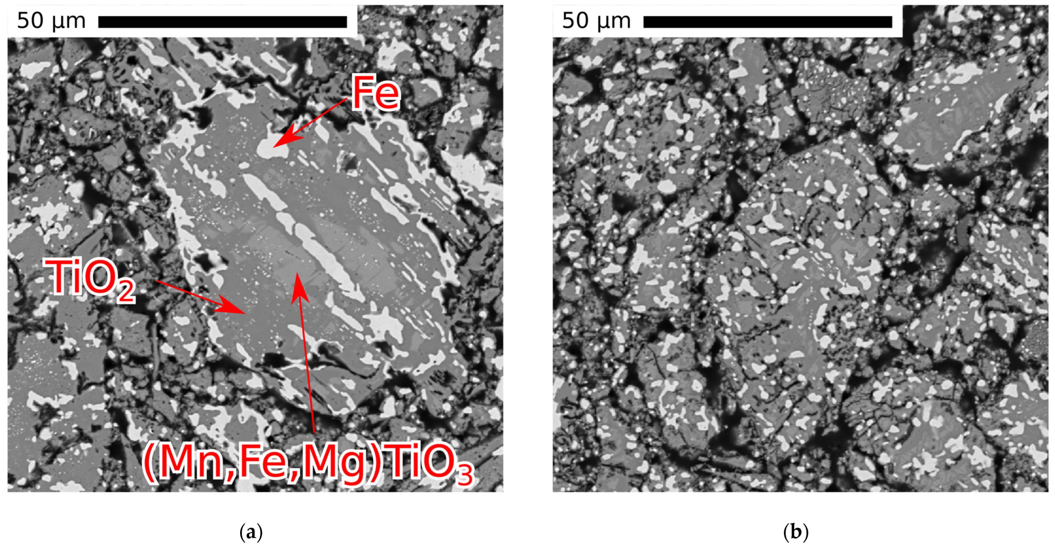
Several reacted pellets were analyzed using an electron probe microanalyzer. The micrographs revealed the formation of micron-sized iron particles deep in the grains of the pellets. Hydrogen is considered to favor nucleation compared with CO gas as the H2 molecules have higher diffusivity overall leading to the easier formation of small iron particles upon reduction [9,17]. Thus, the present work looked at the possible influence of the water content in the gas on the iron particle size with the hypothesis that a higher water content is detrimental to diffusivity and thus to nucleation, therefore promoting growth instead. However, no conclusive evidence was obtained. Figure 9 shows two micrographs of the reacted materials. The inner part of the pellet, shown in Figure 9a, exhibits some zoning phenomena where manganese and magnesium appear to have diffused inwards, while iron diffused outwards. Figure 9b, which depicts the same sample but in the outer part of the pellet, shows the large amount of small iron particles formed throughout the reacted grains.

3.6. Curve Fitting of the Reduction Degree

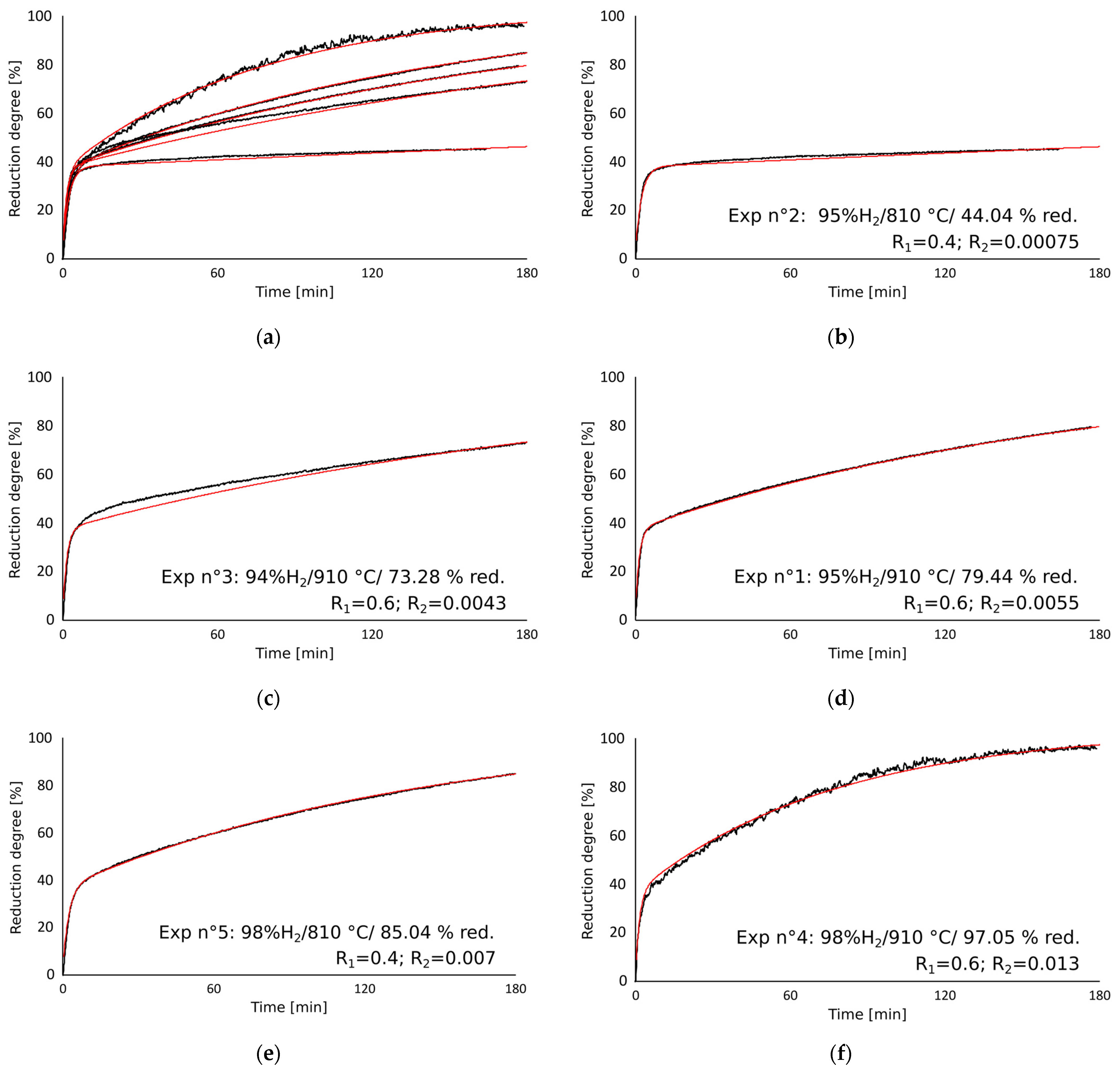
As a first step of the modeling work, R1 and R2, used as parameters in the rate Equations (14)–(16) were determined to fit the reduction degree curves. As the first reaction was not expected to depend significantly on the gas composition, R1 was chosen so that experiments at similar temperatures had the same R1 value. In addition, and as explained in the preceding sections of this work, an incongruity was observed in the curves; this was attributed to changes in the gas flow and composition. To compensate for this incongruity, the fitted curves were constructed with an additional 5% offset. The full reduction of iron can thus theoretically bring the curves to 105% given how the reduction degree is constructed. The results are shown in Figure 10, with the red curves corresponding to the model.
The best fits obtained by selecting the parameters R1 and R2 were very close to the experimental curves, except for experiment 3 at 1183 K (910 °C). This curve was further considered an outlier: The break in the curve, characteristic of the end of the first reaction stage, was found at a reduction degree significantly higher than in the other experiments. Note that experiments 6 to 10 were not fitted by this method.

3.7. Modeling of the Reduction Process with Calculations

After R1 and R2 were obtained by curve fitting for experiments 1–5, the rate constant was calculated based on Equation (13). The rate constant k2 should therefore not depend on the gas composition and should be equal for experiments carried out at the same temperatures.
Two strategies were used to determine k2 and the hydrogen equilibrium partial pressure. First, the equilibrium partial pressures of hydrogen were obtained via thermodynamic calculations at a given temperature using FactSage 8.0, and k2 was deduced at each temperature. Alternatively, the equilibrium partial pressure was determined using a solver to minimize the difference between the calculated k2 values. In this process, only experiments 1, 2, 4 and 5 were considered, 3 being considered an outlier. The results of the two methods are presented in Table 3. It should be noted that the equilibrium partial pressures calculated by FactSage 8.0 were close to those obtained by minimizing the difference between the k2 values. Further, it was considered that the values calculated using FactSage 8.0 were acceptable for the system studied.
Finally, apparent activation energies for the two reactions were determined from the experiments available using Equation (20). The calculated values for the apparent rate constant pre-exponential factors and activation energies are given in Table 4.
E a , i = Rln k i T 1 k i T 2 1 T 2 1 T 1
The non-isothermal nature of the experiments was accounted for by allowing the equilibrium partial pressure and the temperature to vary as a function of time. The experimental measurements of the temperature in the middle of the charge were used in this case. Small variations in the kinetic constants were necessary to maintain a good fit with the reduction degree. The new apparent rate constant pre-exponential factors and activation energies giving a good fit are reported in Table 5. The values for the trivalent to divalent state reduction were more affected as the changes in temperature coincided with the occurrence of the reaction.
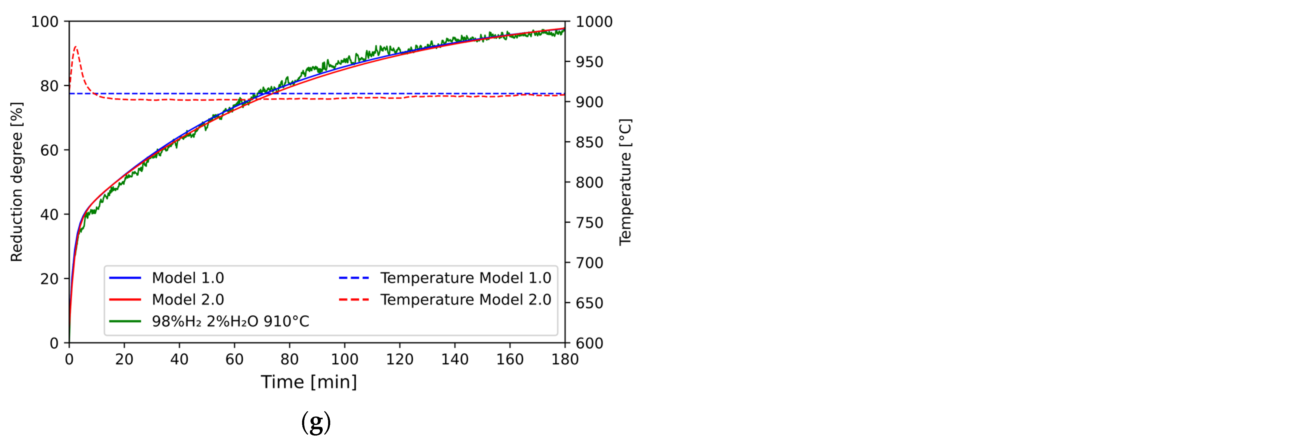
Figure 11 shows (in green) the reduction degree curves as obtained by weight measurements as well as (in blue) the modeled curve assuming isothermal conditions and (in red) non-isothermal conditions. The corresponding temperatures for the isothermal and non-isothermal cases are shown with dashed lines of similar colors. Both the isothermal and the non-isothermal models fit well with the reduction degree calculated from the weight changes, although some deviations can be observed in some cases. The kinetic values of the non-isothermal model are considered more accurate.

3.8. Predictive Reduction Heatmap

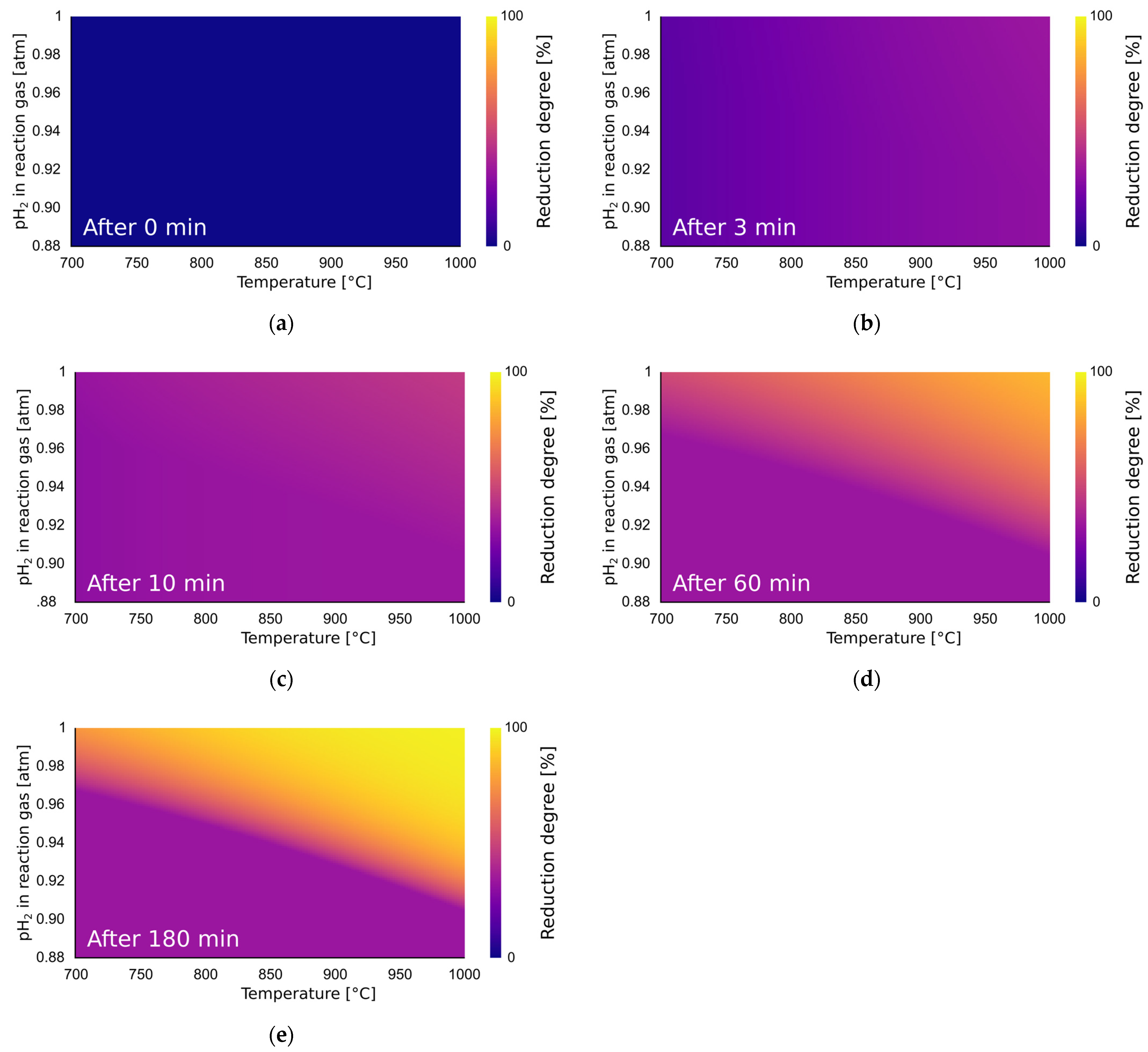
A reduction degree heatmap was calculated based on the kinetics parameters of Model 1.0. This allowed for the visualization of how temperature, hydrogen partial pressure and time interacted. Because this calculation is predictive, and based on the isothermal conditions, the kinetic parameters of Model 1.0 were preferred. The calculation method was analogous to what was performed in the previous section with python and the SciPy module [26] but applied to every (T; pH2) couple in a 151 × 121 grid for temperatures between 700 and 1000 °C and partial pressures of hydrogen between 0.88 and 1 atm. One notable difference is that the 5% mismatch that was introduced to fit the experimental curve was removed here; it is considered to have been linked to the gas flow rather than the reduction process.
Figure 12 shows selected timeframes of the heatmap at 0, 3, 10, 60 and 180 min after the introduction of the reducing gas mixture. At 0 min, no reduction had occurred. After 3 min, the reduction had already progressed significantly in all the conditions as can be observed by the change in color. This is because the first stage, the reduction of trivalent to divalent iron, was nearly not affected by the partial pressure of hydrogen in the given conditions (it is not affected at all in the model). Temperature was therefore the only parameter; this can be observed in Figure 12a, in which there is a slight gradient moving toward higher temperatures. After 10 min of reduction, the first stage of reduction was nearly finished at all the conditions considered, and the reduction degree was close to 30% even at 700 °C and 0.88 atm of hydrogen. For the most reducing conditions, in the top right corner, the second reduction stage had significantly progressed. After 60 min, as shown in Figure 12c, the equilibrium partial pressure for the metallization reaction could be recognized: below the line, the reduction degree is plateauing after the completion of the trivalent to divalent iron reduction. Above the line, the reduction continues; it is favored by the driving force (distance to the equilibrium partial pressure line) and temperature (towards the right side). Finally, 180 min after the introduction of the reaction gas, full or nearly full conversion was expected for the most reducing conditions (high temperature, low water vapor). To a certain extent, the reduction studied here is thus an optimization problem between temperature, time and gas purity: lowering one parameter can be compensated by the increase in another.

4. Conclusions

This study shows that a H2-H2O gas mixture can reduce pre-oxidized ilmenite and form metallic iron, even with 5–6% water vapor. The reduction proceeds in two stages, with a straightforward trivalent to divalent reduction, followed by a slower metallization reaction. The driving force for the metallization reaction is the main factor in determining the rate within the conditions studied. A kinetic model, Model 1.0 based on isothermal conditions, was proposed. The apparent activation energies Ea1 = 43.2 kJ/mol and Ea2 = 50.8 kJ/mol were obtained for the first and second reaction, respectively. From this model, predictive heatmaps of reduction degree as a function of temperature, gas composition and time were computed. A second model taking into account the variation in temperatures upon reduction, Model 2.0, was also proposed. The apparent activation energies Ea1 = 50 kJ/mol and Ea2 = 51 kJ/mol were obtained for the first and second reactions using this second model.

Author Contributions

Conceptualization, V.C. and E.R.; methodology, V.C.; software, V.C.; validation, V.C.; formal analysis, V.C.; investigation, V.C.; resources, E.R.; data curation, V.C.; writing—original draft preparation, V.C.; writing—review and editing, E.R.; visualization, V.C.; supervision, E.R.; project administration, E.R.; funding acquisition, E.R. All authors have read and agreed to the published version of the manuscript.

Funding

This research was funded by the Research Council of Norway, grant number 280968, with financial contributions from the Research Council and the industrial project partners Elkem, Eramet, Finnfjord, TiZir and Wacker.

Data Availability Statement

The data presented in this study are available on request from the corresponding author.

Acknowledgments

The authors gratefully acknowledge the financial support from the Research Council of Norway and the industrial partners Elkem, Eramet, Finnfjord, TiZir and Wacker.

Conflicts of Interest

The authors declare no conflict of interest.

References

  1. Patisson, F.; Mirgaux, O. Hydrogen Ironmaking: How It Works. Metals 2020, 10, 922. [Google Scholar] [CrossRef]
  2. Pei, M.; Petäjäniemi, M.; Regnell, A.; Wijk, O. Toward a Fossil Free Future with HYBRIT: Development of Iron and Steelmaking Technology in Sweden and Finland. Metals 2020, 10, 972. [Google Scholar] [CrossRef]
  3. Wang, R.R.; Zhao, Y.Q.; Babich, A.; Senk, D.; Fan, X.Y. Hydrogen Direct Reduction (H-DR) in Steel Industry—An Overview of Challenges and Opportunities. J. Clean. Prod. 2021, 329, 129797. [Google Scholar] [CrossRef]
  4. Cavaliere, P.D.; Perrone, A.; Silvello, A. Water Electrolysis for the Production of Hydrogen to Be Employed in the Ironmaking and Steelmaking Industry. Metals 2021, 11, 1816. [Google Scholar] [CrossRef]
  5. Spreitzer, D.; Schenk, J. Iron Ore Reduction by Hydrogen Using a Laboratory Scale Fluidized Bed Reactor: Kinetic Investigation—Experimental Setup and Method for Determination. Met. Mater. Trans. B 2019, 50, 2471–2484. [Google Scholar] [CrossRef]
  6. Scharm, C.; Küster, F.; Laabs, M.; Huang, Q.; Volkova, O.; Reinmöller, M.; Guhl, S.; Meyer, B. Direct Reduction of Iron Ore Pellets by H2 and CO: In-Situ Investigation of the Structural Transformation and Reduction Progression Caused by Atmosphere and Temperature. Miner. Eng. 2022, 180, 107459. [Google Scholar] [CrossRef]
  7. Metolina, P.; Ribeiro, T.R.; Guardani, R. Hydrogen-Based Direct Reduction of Industrial Iron Ore Pellets: Statistically Designed Experiments and Computational Simulation. Int. J. Miner. Metall. Mater. 2022, 29, 1908–1921. [Google Scholar] [CrossRef]
  8. TiZir Titanium & Iron, a Pioneer of Metallurgy in Norway. Available online: https://www.eramet.com/en/tizir-titanium-iron-pioneer-metallurgy-norway (accessed on 8 April 2022).
  9. Zhao, Y.; Shadman, F. Reduction of Ilmenite with Hydrogen. Ind. Eng. Chem. Res. 1991, 30, 2080–2087. [Google Scholar] [CrossRef]
  10. Briggs, R.A.; Sacco, A. Hydrogen Reduction Mechanisms of Ilmenite between 823 and 1353 K. J. Mater. Res. 1991, 6, 574–584. [Google Scholar] [CrossRef]
  11. Vijay, P.L.; Venugopalan, R.; Sathiyamoorthy, D. Preoxidation and Hydrogen Reduction of Ilmenite in a Fluidized Bed Reactor. Met. Mater. Trans. B 1996, 27, 731. [Google Scholar] [CrossRef]
  12. Donnely, R.P.; Brennan, L.J.; McMulan, W.; Rouiliard, A. Reduction of Iron Oxide in Ilmenite Beach Sands. Part II-by Gaseous and by Solid Carbon Reductants as a Preliminary Step in Beneficiation by Removal of the Reduced Iron Oxide. Aust. Min. 1970, 62, 52–59. [Google Scholar]
  13. Jones, D.G. Kinetics of Gaseous Reduction of Ilmenite. J. Appl. Chem. Biotechnol. 1975, 25, 561–582. [Google Scholar] [CrossRef]
  14. Sun, K.; Takahashi, R.; Yagi, J. Reduction Kinetics of Cement-Bonded Natural Ilmenite Pellets with Hydrogen. ISIJ Int. 1992, 32, 496–504. [Google Scholar] [CrossRef]
  15. Wang, Y.; Yuan, Z.; Matsuura, H.; Tsukihashi, F. Reduction Extraction Kinetics of Titania and Iron from an Ilmenite by H2–Ar Gas Mixtures. ISIJ Int. 2009, 49, 164–170. [Google Scholar] [CrossRef]
  16. Bardi, G.; Gozzi, D.; Stranges, S. High Temperature Reduction Kinetics of Ilmenite by Hydrogen. Mater. Chem. Phys. 1987, 17, 325–341. [Google Scholar] [CrossRef]
  17. Lobo, S.C. Experimental Investigations and Modelling of Solid-State Ilmenite Reduction with Hydrogen and Carbon Monoxide; NTNU: Trondheim, Norway, 2015; ISBN 978-82-326-1275-8. [Google Scholar]
  18. Sun, K.; Akiyama, T.; Takahashi, R.; Yagi, J. Hydrogen Reduction of Natural Ilmenite in a Fluidized Bed. ISIJ Int. 1995, 35, 360–366. [Google Scholar] [CrossRef]
  19. Kapilashrami, A.; Arvanitidis, I.; Sichen, D. Investigation of the Kinetics of Reduction of Iron Titanate (FeTiO3) by Hydrogen. High Temp. Mater. Process. 1996, 15, 73–82. [Google Scholar] [CrossRef]
  20. Zhang, G.-H.; Chou, K.-C.; Zhao, H.-L. Reduction Kinetics of FeTiO3 Powder by Hydrogen. ISIJ Int. 2012, 52, 1986–1989. [Google Scholar] [CrossRef]
  21. Dang, J.; Hu, X.; Zhang, G.; Hou, X.; Yang, X.; Chou, K.-C. Kinetics of Reduction of Titano-Magnetite Powder by H2. High Temp. Mater. Process. 2013, 32, 229–236. [Google Scholar] [CrossRef]
  22. Dang, J.; Zhang, G.; Chou, K. Kinetics and Mechanism of Hydrogen Reduction of Ilmenite Powders. J. Alloys Compd. 2015, 619, 443–451. [Google Scholar] [CrossRef]
  23. Lobo, S.C.; (Eramet Titanium and Iron). Personal communication, 2021.
  24. Hayes, P.C. Stability Criteria for Product Microstructures Formed on Gaseous Reduction of Solid Metal Oxides. Met. Mater. Trans. B 2010, 41, 19–34. [Google Scholar] [CrossRef]
  25. Bale, C.W.; Bélisle, E.; Chartrand, P.; Decterov, S.A.; Eriksson, G.; Gheribi, A.E.; Hack, K.; Jung, I.-H.; Kang, Y.-B.; Melançon, J.; et al. FactSage Thermochemical Software and Databases, 2010–2016. Calphad 2016, 54, 35–53. [Google Scholar] [CrossRef]
  26. Virtanen, P.; Gommers, R.; Oliphant, T.E.; Haberland, M.; Reddy, T.; Cournapeau, D.; Burovski, E.; Peterson, P.; Weckesser, W.; Bright, J.; et al. SciPy 1.0: Fundamental Algorithms for Scientific Computing in Python. Nat. Methods 2020, 17, 261–272. [Google Scholar] [CrossRef] [PubMed] [Green Version]
  27. Schanche, T.; (SINTEF, Trondheim, Norway). Personal communication, 2021.
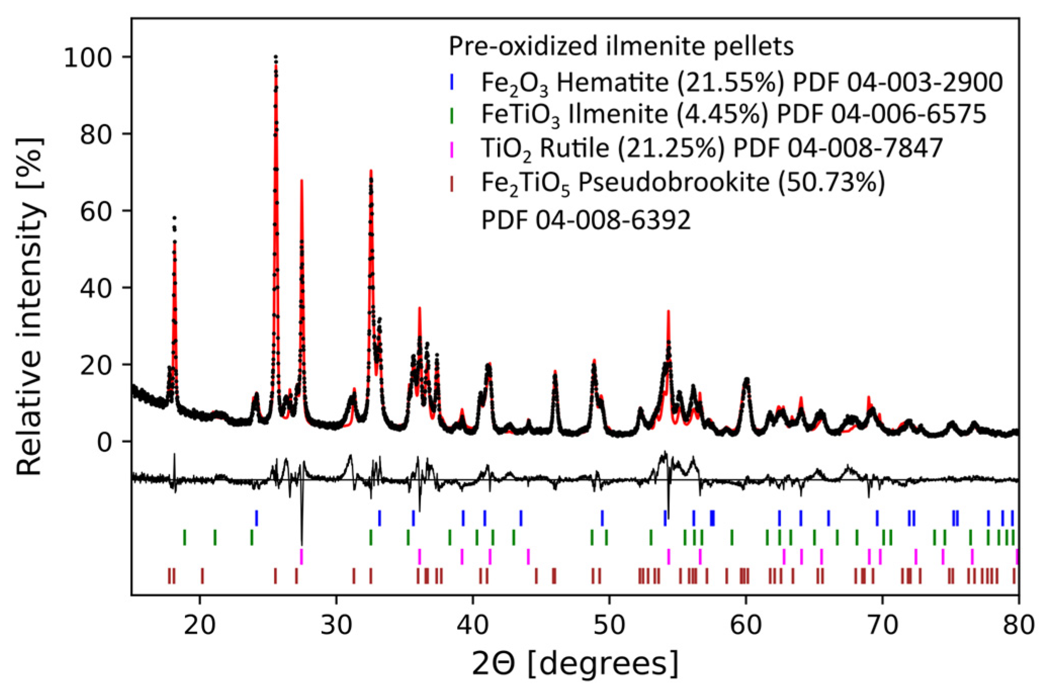
Figure 1. X-ray diffraction patterns for the pre-oxidized ilmenite pellets. The measured data are given as black dots and the fitted data are given as a red line. The difference between the fit and the measured pattern is plotted below the pattern. The estimate of each phase in wt.% based on Rietveld fitting is given in the legend, the balance being quartz.
Metals 13 00332 g001
Figure 2. Schematics of the thermogravimetric setup. The colored arrows illustrate how the gas travels down the double wall and heats up before it reaches the sample at the bottom.
Metals 13 00332 g002
Figure 3. Calculated equilibrium partial pressure for the metallization reaction in red. The black crosses and the experiment number show the conditions of temperature and gas composition for the experimental work. Experiment 9 appears twice as the gas mixture was shifted during the experiment.
Metals 13 00332 g003
Figure 4. Reduction degree as a function of time for the experiments of the study. ‡: (from 100/0 H2/H2O and 7.44 L/min to 93/7 H2/H2O and 8 L/min).
Metals 13 00332 g004
Figure 5. Mass of gas in the crucible as a function of gas mixture and temperature (from the ideal gas law).
Metals 13 00332 g005
Figure 6. Measured mass increase after flow change from 1 L/min to 8 L/min argon.
Metals 13 00332 g006
Figure 7. Reduction degree as a function of time for experiments 8 (pure H2), 9 (pure H2, then H2-H2O) and 10 (H2-H2O) all carried out at 860 °C. The introduction of H2O in experiment 9 led to the reoxidation of iron.
Metals 13 00332 g007
Figure 8. X-ray diffraction patterns for experiments 1–5. The graphs are presented from least to most reduced. The measured data are given as black dots and the fitted data are given as a red line. The difference between the fit and the measured pattern is plotted below the pattern. (a) Experiment at 810 °C and 95%H2; (b) experiment at 910 °C and 94%H2; (c) experiment at 910 °C and 95%H2; (d) experiment at 810 °C and 98%H2; (e) experiment at 910 °C and 98%H2.
Metals 13 00332 g008
Figure 9. Electron probe micrographs of a pellet reacted at 910 °C for 180 min with a gas containing 98%H2. (a) View of the inner part of the pellet; (b) view of the outer layer of the pellet.
Metals 13 00332 g009
Figure 10. Reduction degree as a function of time according to (in black) the experimental measurement and (in red) the model. (a) All the following curves are shown together; (b) experiment at 810 °C and 95%H2; (c) experiment at 910 °C and 94%H2; (d) experiment at 910 °C and 95%H2; (e) experiment at 810 °C and 98%H2; (f) experiment at 910 °C and 98%H2.
Metals 13 00332 g010
Figure 11. Reduction degree as a function of time according to (in green) the experimental measurement; (in blue) the isothermal model “Model 1.0”; and (in red) the non-isothermal model “Model 2.0”. Corresponding temperatures used are indicated with dashed lines of the same color. (a) Experiment at 860 °C and 93%H2; (b) experiment at 810 °C and 95%H2; (c) experiment at 710 °C and 98%H2; (d) experiment at 860 °C and 95%H2; (e) experiment at 910 °C and 95%H2; (f) experiment at 810 °C and 98%H2; (g) experiment at 910 °C and 98%H2.
Metals 13 00332 g011aMetals 13 00332 g011b
Figure 12. Reduction degree heatmap for temperatures between 973 and 1273 K (700–1000 °C) and hydrogen partial pressure between 0.88 and 1 atm. Images correspond to (a) 0 min of reaction; (b) 3 min of reaction; (c) 10 min of reaction; (d) 60 min of reaction; (e) 180 min of reaction.
Metals 13 00332 g012
Table 1. Composition (wt.%) of the investigated pellets. Most oxide content levels were based on XRF, while FeO was measured through wet chemistry techniques data from [23]. Fe2O3 was calculated from the other two methods.
Al2O3Fe(tot)MgOMnOSiO2TiO2V2O5FeOFe2O3
0.631.30.41.50.550.90.30.943.7
Table 2. Experimental parameters for this study.
Sample
Mass (g)
Control
Temperature (°C)
Expected Crucible Temperature a (°C)Holding Time
(min)
Gas Composition (%H2/%H2O)Gas Flow (L/min)
1201.4886091018095/58
2200.24760810163 b95/58
3200.2986091018094/68
4200.0586091018098/28
5200.0776081018098/28
6199.9681086018095/58
7200.0166071018098/28
8200.01810860180100/0 c7.44 c
9200.0181086060100/0→93/7 d7.44→8 d
10199.9581086018093/78
a, “expected crucible temperature” corresponds to an estimate based on the “control temperature”; b, experiment 2 was interrupted 17 min before planned stop; c, experiment was completed with pure hydrogen and a lower flow (7.44 L/min); d, experiment started with a pure flow of 7.44 L/min H2; then, water vapor was added to the mix at 8 L/min.
Table 3. Equilibrium partial pressure and k2 rate constants for experiments 1, 2, 4 and 5 according to the two methods employed, using FactSage or a solver.
T [°C]pH2pH2,eq
FactSage
k2pH2,eq
“Solver”
k2
“Solver”
58100.9800.9480.0110.9460.011
28100.9500.9480.0190.9460.011
49100.9800.9260.0180.9280.018
19100.9500.9260.0170.9280.018
Table 4. Apparent rate constant pre-exponential factors and activation energies according to the isothermal model (Model 1.0).
Reaction Fe3+→Fe2+Reaction Fe2+→Fe
k0,1
[min−1]
Ea1
[kJ/mol]
k0,2
[min−1]
Ea2
[kJ/mol]
48.4443.23.1750.8
Table 5. Apparent rate constant pre-exponential factors and activation energies according to the non-isothermal model (Model 2.0).
Reaction Fe3+→Fe2+Reaction Fe2+→Fe
k0,1
[min−1]
Ea1
[kJ/mol]
k0,2
[min−1]
Ea2
[kJ/mol]
72503.151
Disclaimer/Publisher’s Note: The statements, opinions and data contained in all publications are solely those of the individual author(s) and contributor(s) and not of MDPI and/or the editor(s). MDPI and/or the editor(s) disclaim responsibility for any injury to people or property resulting from any ideas, methods, instructions or products referred to in the content.