Abstract
Ultrasonic Joining (U-Joining) is a novel friction-based joining technique that produces through-the-thickness reinforced hybrid joints between surface-structured metals and thermoplastics. The process feasibility has been successfully demonstrated to join metals and unreinforced or fiber-reinforced polymer parts by applying horizontal vibration. However, intense tool wear was observed for the explored combinations of materials, which could diminish the mechanical performance of the produced joints and hinder the process application. These investigations left an unexplored field regarding the application of different vibration modes, which could represent good solutions to minimize the intense tool wear reported. Therefore, the present study aims to explore the application of vertical vibration and to identify possible advantages and disadvantages of this variation. The case-study combination of additively manufactured 316L stainless steel and 20%-short-carbon-fiber reinforced poly-ether-ether-ketone was selected for this purpose. Initially, a set of optimized joining parameters was obtained for the vertical variation following a one-factor-at-a-time approach. In a previous study, the joining parameters were already optimized for the horizontal mode, and the results were used for comparison purposes. Single-lap shear joints were produced using both optimized modes, and the process monitoring indicated that joints produced using vertical vibration reached a lower joining energy input for a given joining time. The produced joints were tested, and joints produced with the horizontal variation achieved higher ultimate lap shear forces than the ones achieved by the vertical ones: 3.6 ± 0.3 kN and 1.6 ± 0.3 kN, respectively. Microstructural investigations at the fractured surfaces showed that this difference is due to insufficient frictional heat generation at the metal-composite interface when vertical vibration is applied. Therefore, the temperatures reached during the joining cycle are not enough to melt the polymer completely at the interface, preventing a complete surface wetting of the metal and reducing the micromechanical interlocking and adhesion bond between the parts, thereby diminishing the mechanical performance of the produced joints.
1. Introduction
The development of lightweight structures represents one of the most viable and researched solutions for transportation industries seeking to comply with exigent greenhouse gas (GHG) emissions targets [1]. By applying the “the right material at the right place” concept, original equipment manufacturers (OEMs) successfully rely on the integration of metals with polymer composites into hybrid structures to reduce weight significantly and improve their vehicles’ energy efficiency [2]. Successful examples of the implementation of these hybrid structures are the Airbus A350 XWB and the Boeing 787 Dreamliner, whose structures are nearly 53% and 50%, respectively, made of CFRP, the rest being made of different metallic alloys [3,4].
Although promising, the metal-composite combination is a complex task, as each presents distinct physical and chemical properties, and this results in low miscibility and distortion of parts during thermal joining [5]. Consequently, traditional processes, such as adhesive bonding and mechanical fasteners, are the most commonly used assembly techniques for joining metals to composites. However, both adhesive bonding and mechanical fastening present limitations that hinder the application of hybrid structures. Adhesive joints can have long curing times and usually present brittle failure and limited load transferability due to their low out-of-plane strength. The installation of fasteners typically introduces stress concentration due to the presence of bolts or rivets. Therefore, new innovative joining techniques have been developed to fabricate metal-polymer or composite hybrid structures to overcome these limitations.
In this context, ultrasonic joining (U-Joining) was developed and introduced as an innovative friction-based joining technique capable of assembling surface-structured metallic parts with unreinforced and fiber-reinforced thermoplastics. By applying through-the-thickness reinforcement (TTR) structures to the metal surface, the process can produce strong hybrid joints with improved out-of-plane strength and loading capabilities and faster assembly cycles [6,7]. A previous study has already addressed the joinability of additively manufactured (AM) 316L stainless steel (316L SS) and unreinforced poly-ether-ether-ketone (PEEK) hybrid joints. This work demonstrated that joints with improved mechanical performance could be produced due to different bonding mechanisms: micro- and macromechanical interlocking, and adhesion forces—which are activated by ultrasonic frictional heating [8]. De Carvalho and Amancio-Filho [9] have also demonstrated that integrating complex AM components using U-Joining represents a new manufacturing route to produce stronger and lightweight hybrid structures. However, these published studies have only addressed joints produced with horizontal vibration, leaving an unexplored field regarding the application of different vibration modes. Therefore, the present study aims to explore the application of vertical vibration and to identify possible advantages and disadvantages of this variation. Here, the joining parameters for the vertical variant were optimized via a one-factor-at-a-time (OFAT) approach for the AM 316L SS and 20%-short-carbon-fiber reinforced PEEK (PEEK-20CF) base materials combination, which were produced via laser powder bed fusion (LPBF) and fused filament fabrication (FFF), respectively. The joining parameters for the same materials combination using horizontal mode were previously optimized and will be applied in the present manuscript. Finally, selected microstructural features and fractography analyses will be addressed to explain the correlation between the joining process, microstructural features, and mechanical performance of the produced hybrid joints.
Ultrasonic Joining (U-Joining)
The U-Joining process can be divided into three phases, independently of the vibration mode applied. Figure 1a,b illustrate the steps at which horizontal and vertical vibration are used, respectively. In Step 1, the parts are placed between the sonotrode and the anvil, with the structured surface of the metal facing the upper surface of the polymer or composite. In the case of horizontal welding, a sonotrode that allows the assembly of a replaceable tool can be used. For vertical joining, the sonotrode normally acts directly at the upper surface of the metallic connector. In Step 2, the sonotrode starts vibrating, and vertical pressure is applied against the parts. The principle of heat generation for both variants is based on the conversion of high-frequency mechanical vibration into heat through (i) combined contact surface at the metal-polymer interfaces, initially between the TTRs’ tips and the polymer surface, and then, after full insertion of the TTRs, between the metallic and polymer flat surfaces; and (ii) intermolecular friction (i.e., viscous dissipation) within the polymer or composite material [10,11,12]. Consequently, a portion of the polymer close to the interface melts or softens (depending on whether semi-crystalline or amorphous polymers are joined), allowing the TTRs insertion into the polymer or composite material. Step 3 is the consolidation phase. As soon as the TTRs are entirely inserted into the polymer, the vibration is interrupted and the pressure is kept constant until the softened or melted layer solidifies. At the end of the process, the sonotrode retracts and the joining cycle is concluded. The produced joints are held by the combined effects of three different mechanisms: macromechanical interlocking due to the presence of TTRs, micromechanical interlocking at the rough metal-polymer interface, and adhesive forces created by the consolidation of the molten layer [8].
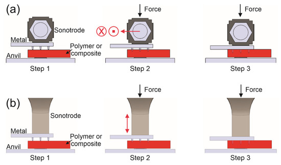
Figure 1.
Schematic representation of U-Joining process steps when using (a) horizontal (Adapted with permission from [8], Elsevier, 2022) and (b) vertical mechanical vibration.
2. Materials and Methods
2.1. Base Materials and Printing Processes
LPBF was used to print 15.5 × 35 × 3 mm surface-structured 316L SS connectors with a building angle of 45° (in relation to the building plate). Pre-alloyed and gas-atomized spherical powder supplied by Carpenter Additive (Philadelphia, PA, USA) was used, and the specimens were printed using a Creator RA (Coherent OR LASER, Dieburg, Germany) equipment. The applied LPBF parameters were previously optimized, resulting in parts with a density of 7.8 ± 0.05 g/cm3 or 98 ± 0.6% compared to bulk material (8 g/cm³ [13]). The density of the printed parts was measured using Archimedes’ principle according to the ASTM B962-15 [14]. Additionally, the average surface roughness (Sa) was evaluated for the same printed parts using a VHX6000 digital microscope (Keyence, Osaka, Japan), resulting in a Sa of 21 ± 2 µm. Table 1 presents the optimized parameters set used.

Table 1.
Optimized LPBF parameters for 316L SS.
The averaged chemical composition of printed parts was measured via optical emission spectroscopy (OES) using a Spectrolab M8 (SPECTRO Analytical Instrument, Kleve, Germany) equipment and the obtained values are listed in Table 2. The obtained values are in accordance with the typical values for this alloy [13].
Table 2.
Chemical composition of the printed 316L SS parts.
Figure 2 shows the dimensions of the connectors and a detailed view of one of the six round-tip conical TTRs used in this work, which was based on previous studies [6,7,8,9]. An undercut with a radius of 0.2 mm was applied at the base of the pins to shift the stress concentration from this region and improve the mechanical interlocking between the materials after the joining process.
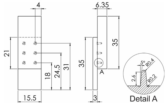
Figure 2.
Geometry dimensions of the single lap-shear specimens used in this work, including a detailed view of the TTR dimensions. All dimensions are given in mm. Adapted with permission from [8], Elsevier, 2022.
Figure 2 also presents the dimensions (15.5 × 35 × 6.35 mm) of the flat FFF PEEK-20CF samples applied in this study. A 1.75-mm-diameter filament supplied by 3DXTech (Grand Rapids, MI, USA) was used, and the samples were printed in a FUNMAT HT (Intamsys, Shanghai, China) FFF-3D-printer. The PEEK-20CF parts were printed with previously optimized parameters, which were identified by considering multiple loading conditions (tensile, bending and impact strength). The values used are listed in Table 3. The building plate surface was treated with polyvinylpyrrolidone (PVP) glue before every printing cycle, to enhance the adhesion of the part to the platform.
Table 3.
Optimized FFF parameters for PEEK-20CF.
2.2. U-Joining and Joints Characterization
The joining process was carried out using two ultrasonic machines: an Ultraweld L20 horizontal or lateral driven welder and a 921 AES vertical welder, both produced by Branson Ultrasonics (Brookfield, WI, USA). The two joining devices operate with a fixed sonotrode vibration frequency of 20 kHz, and have different maximum powers: 4 kW for the horizontal and 2 kW for the vertical welder. Additionally, both machines can be controlled by different modes: welding energy, time or position of the sonotrode. In the energy mode, the power supply monitors and integrates the power as a function of time until the preset energy value is reached. At this point, the power supply discontinues the vibration independently of the time. In the time mode, on the other hand, the vibration remains on for a predefined period, independently of the energy level reached. Finally, in the position control mode, the power supply monitors an encoder on the actuator and continues to apply ultrasonic energy to the parts until the preset displacement is reached (usually the distance between the sonotrode and the anvil).
Generally, the energy mode is more commonly used for process control in metal ultrasonic welding. As stated by Beyer [15], the ultrasonic welding of metals consists of interrelated and complex processes such as plastic deformation, work hardening, breaking of contaminant films, fatigue crack formation and propagation, fracture, generation of heat by friction and plastic deformation, re-crystallization, and interdiffusion. All these different phenomena result in barriers to process control to ensure that a proper energy input level is reached from weld to weld when the other two modes are used. On the other hand, Tao et al. [16] reported that, in plastic ultrasonic welding, the heat generation (mainly composed of interfacial and intermolecular friction–i.e., viscous dissipation) is steadier from weld to weld, compared to metal ultrasonic welding. Consequently, time mode is ideal for process control in polymer welding. Following this tendency, the U-Joining parameters using a horizontal welder had already been optimized in a previous study, using the energy mode for the proposed materials combination to maximize the achieved ultimate lap shear force (ULSF). The selected parameters are presented in Table 4. The produced joints achieved a ULSF of 3.6 ± 0.1 kN and a displacement at break (DaB) of 2.4 ± 0.1 mm. The resulting joining time for this condition was approximately 3 s.
Table 4.
Optimized U-Joining horizontal parameters for 316L SS/PEEK-20CF hybrid joints.
Initial tests were also performed using the energy control mode for the vertical ultrasonic; however, the results showed that the system could not reach the energy levels reached by the horizontal mode, even with longer joining cycles. Therefore, a one-factor-at-a-time (OFAT) approach was followed to investigate the correlation between joining energy and joining time using different periods: 1, 2, 3, 4 and 8 s. The booster and horn were kept constant for the vertical variant, resulting in an amplitude of approximately 60 µm. A fixed joining/cylinder pressure (JP) of 20 psi was used for this variant, as higher values resulted in the machine’s overloading, which will be addressed in detail later.
The produced single overlap specimens (presented in Figure 2) were tested under a quasi-static lap-shear condition. The tests were performed at room temperature, with a 1 mm/min crosshead speed, using a Zwick universal testing machine (Zwick/Roell Group, Ulm, Germany) equipped with a 100 kN load cell. Microstructural analyses of selected joined samples were performed by cutting the specimens, producing cross-sections near the center of one of the TTRs rows, and preparing the exposed surface by standard metallographic preparation. The interface between both materials was then examined by optical microscopy using an Axio Observer 7 (Zeiss, Oberkochen, Germany) microscope. Finally, the fractured surface of tested lap shear samples was analyzed via scanning electron microscopy (SEM) using a Tescan Mira 3 (TESCAN, Brno, Czech Republic).
3. Results and Discussion
As previously mentioned, the U-Joining parameters had already been optimized for horizontal welding using the selected material combination and the energy control mode (the selected parameters are presented in Table 4). As defined by Benatar [17], modern ultrasonic welders operate in a closed loop when using this mode, where the power dissipated in the ultrasonic transducer is measured and integrated along the joining cycle until the desired EJ is achieved (area under the time x power curve). The obtained curve for this optimized horizontal condition is presented in Figure 3. The curve also confirms that the joining cycle for the optimized condition is approximately 3 s, where the vibration is completely ceased.
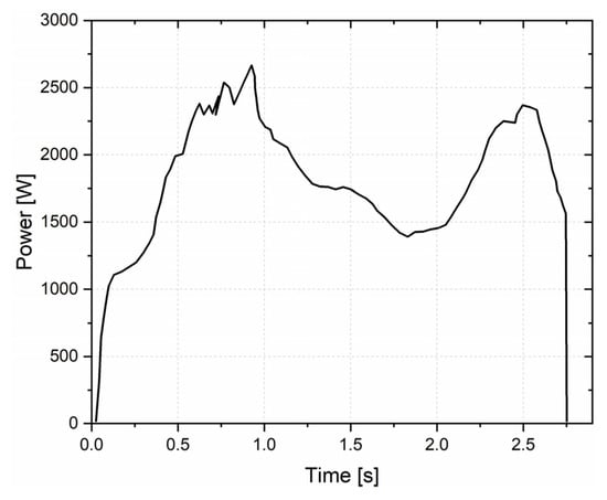
Figure 3.
Time x power curve for the optimized U-Joining process using horizontal vibration.
Figure 3 shows that, at the beginning of the ultrasonic process, a solid-solid system occurs, and an abrupt increase in the power level is observed due to the application of a normal force and vibration, reaching levels above 2500 W. Here, the primary heating mechanism is based on the Coulomb or solid friction phenomenon, where the surfaces from both materials are frictioned against each other, generating heat [18]. As the process advances, more heating is generated due to the friction between the parts and the polymeric chains (intermolecular friction), until the reached temperature is high enough to locally melt a small volume of the polymer matrix directly below the TTRs, decreasing the polymeric matrix viscosity and allowing the beginning of the TTR penetration [19]. After this initial phase, the process becomes more stable, resulting in a solid-molten state, as a more substantial molten PEEK volume is formed around the vibrating TTRs. Feistauer [18] assumed that heat input and heat outflow are equalized in these levels, as a balance between polymer melting and molten material outflow rates. This assumption explains the decrease in the power levels shown at the middle of the curve. When the TTRs are completely inserted into the composite, their vibrational motion is constrained by the adjacent volume of polymeric material. Therefore, to compensate for this resistance, the ultrasonic joining system increases the electrical power to keep the sonotrode vibration constant, as shown at the end of the curve. The combination of energy input and pressure forces the molten PEEK-20CF against the metallic surface, wetting the surface cavities of the rough LPBF 316L SS and improving the micromechanical interlocking and adhesive bonding mechanisms.
Once the joining conditions for the horizontal variant were defined, the tests applying vertical vibration started. Initial tests using the energy control mode with an EJ of 5000 J resulted in the early stoppage of the joining process due to the machine’s overloading warning signs. The overload sign is a protection mechanism of the machine, which indicates that the joining parameters used are too high and that the available power is no longer sufficient to generate or sustain the vibration during the given mechanical load. At this point, the power supply stops due to an overload [20]. This issue hints that the vertical variation cannot work with such high EJ for the material conditions and that lower levels should be used.
Further tests to reduce EJ using the energy mode resulted in poor process control, as large discrepancies were observed in the joining time when multiple joints were produced using the same EJ value. Additionally, other studies have reported that the time mode provides better process control when vertical vibration is used (as the process is less dependent on the surface condition due to lower friction between the sonotrode and the joining parts) [10]. Consequently, the time control mode was selected for the vertical variant to improve the process reliability. The joining time (JT) was optimized via OFAT analyses, in which its influence on the joint formation was assessed, aiming to compare the joint’s behavior and energy input along the joining cycle. The obtained time x power curves for five different JT values (1, 2, 3, 4 and 8 s) are presented in Figure 4. The EJ values (area under the curves) are also included for each condition.
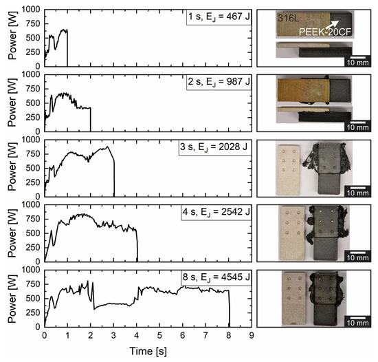
Figure 4.
Comparison between energy input along joining cycles for different JT values: 1, 2, 3, 4 and 8 s and overview of their respective produced joints.
All of the curves presented a similar profile to that of the curve for the horizontal variation (Figure 3), and the heating mechanisms and joint formation can be assumed to be similar to those previously described. It is possible to observe that by increasing JT, EJ is automatically increased as the vibration is applied for longer. The curves show that even when a JT of 8 s is used, an EJ of 5000 J is still not reached. These values indicate that the energy input in this variation is much lower for a given time due to the nature of the vertical motion and the lower JP used, which results in a lack of constant contact and pressure between the sonotrode and the metallic connector. The power levels reached (below 1000 W) are also much lower than those reached by the horizontal variation (below 2500 W). Additionally, overviews of produced representative joints with the different JT values analyzed are presented beside each curve. The photos were taken directly after each joining cycle, when the parts were removed from the sample holder. As one can see, the images demonstrate that for joints produced with a JT > 3 s, most of the TTRs are already damaged during the joining cycle, resulting in the total adhesive failure of the joints before any mechanical testing. Based on that, the optimized condition was fixed with a JT of 2 s, as lack of penetration or other visual defects were not identified for this condition.
Quasi-static lap shear tests were conducted with samples produced using the optimized conditions for both variants to compare their mechanical performance. Representative force x displacement curves are presented for both conditions in Figure 5a, as well as an overview of the produced horizontal (Figure 5b) and vertical (Figure 5c) joints. By analyzing the top view of the U-Joint presented in Figure 5b, one can observe that marks resembling the tool geometry are left on the surface of the metallic connector when horizontal vibration is used. On the other hand, Figure 5c indicates that such strong grooves are not produced in the vertical variant for a JT of 2 s. This difference indicates that the vertical mode represents a good solution to minimize the intense tool wear reported in the literature [8,18] when the horizontal mode is used.
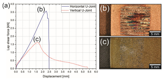
Figure 5.
(a) Comparison between the mechanical performance of optimized horizontal and vertical U-Joints, and (b,c) show an overview of each of them, respectively.
Additionally, the curves in Figure 5a indicate that the horizontal U-Joints achieved higher ULSFs than those achieved by the vertical joints: 3.6 ± 0.3 kN and 1.6 ± 0.3 kN (up to 2.25 times), respectively. On the other hand, the curves also indicate that the displacement at break (DaB) of vertical U-Joints is more than two times higher than those from the horizontal U-Joints. Since the TTRs were completely inserted into the composite part (macromechanical interlocking), one can assume that this difference might be related to lower micromechanical interlocking or adhesion bonding between the parts when vertical motion is applied. Therefore, microstructural analyses were performed for both conditions to understand the mechanical performance observed for these metal-composite hybrid joints. Firstly, optical microscopy investigations were performed at the metal-composite interface. Figure 6 shows a cross-sectional view of the optimized conditions and microstructural details of two different regions for each sample.
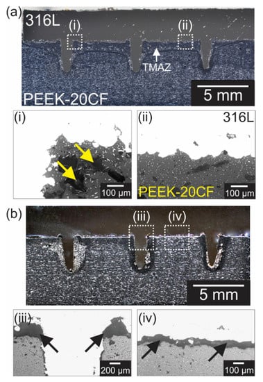
Figure 6.
Cross-sectional view of optimized 316L/PEEK-20CF hybrid joints, with detailed images of the metal-composite interface for (a) horizontal and (b) vertical U-Joints. (i–iv) show selected regions from both conditions.
Figure 6a and its respective detail images (i and ii) show that, for the horizontal variation, molten PEEK-20CF could flow around the rough surface produced by the LPBF process (average surface roughness of 21 ± 2 µm, as presented in Section 2.1) and penetrate the 316L SS surface cavities along the whole overlap area and TTRs region. These results indicate that strong micromechanical interlocking was achieved, contributing to additional adhesion forces at the interface and enhancing the mechanical performance of hybrid joints. The arrows in Figure 6a(i) indicate a minimum amount of voids inside the PEEK-20CF part, which can be associated with residual porosity of the FFF printed parts (intra and inter-bead voids) and thermal-induced defects, such as entrapped gases during the solidification of the polymer after the joining process [8,9,18]. Additionally, Figure 6a shows that the frictional heat combined with the TTR insertion created a thermo-mechanical affected zone (TMAZ) close to the metal-composite interface.
Figure 6b and its respective detail images (iii and iv) demonstrate that, for the vertical variation, the TTRs were also completely inserted. However, a proper micromechanical interlocking between the parts was not achieved, as almost the whole overlap area presents lack of filling of the metal surface cavities–indicated by the arrows in Figure 6b(iii),b(iv). This behavior indicates that the energy input reached in the vertical variation could not melt enough PEEK-20CF material to wet the whole metal surface. The low heat development was also not enough to create a visual TMAZ along the overlap area.
SEM analyses were performed on the fracture surface of selected specimens after the lap shear tests for both horizontal and vertical conditions. This investigation aimed to identify if micromechanical interlocking was achieved for each variant and in which regions it concentrated. The results are presented in Figure 7.
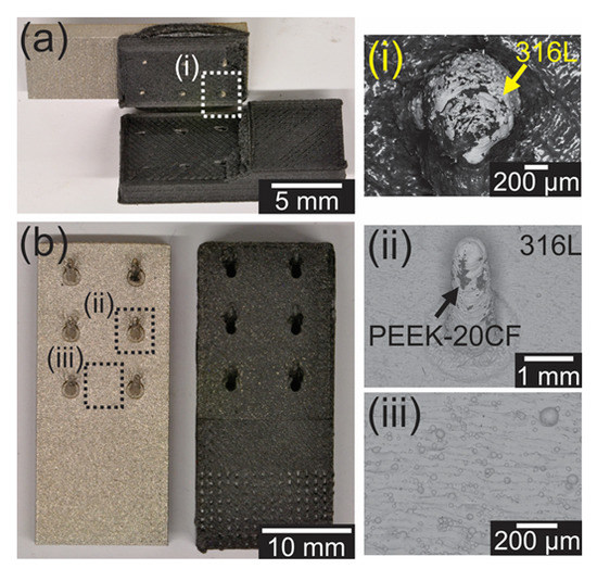
Figure 7.
(a) Horizontal and (b) vertical U-Joints tested under lap shear. (i–iii) show SEM analyses of selected regions on the fracture surfaces from both conditions.
Figure 7a,b show overviews of two samples produced with horizontal and vertical vibrations, respectively, as well as SEM analyses of selected regions from both of them. Figure 7a shows that most of the surface of the 316L SS connector is covered in PEEK-20CF and indicates that the composite part failed by net tension at the end of the overlap area and delamination in the overlap region. Additionally, the detailed view of the exposed TTRs surface (Figure 7a(i)) shows a mixture of cohesive and adhesive failure in that region. These results confirm, once again, that the composite had efficiently wetted out the 316L SS surface for the samples produced with horizontal vibration, forming strong bonds between both materials. On the other hand, Figure 7b indicates adhesive failure in almost the whole overlap area when vertical motion was used. Figure 7b(ii) indicates that a small portion of PEEK-20CF has adhered to the TTRs region, but Figure 7b(iii) shows that no polymer adhesion was identified on the flat region of the metallic connector. As demonstrated by De Carvalho and Amancio-Filho [8], the TTRs act as energy directors during the joining cycle, resulting in the development of frictional heat around them, which melts a portion of polymer in their surroundings, wetting the metal surface in the TTRs regions. Since additional energy directors were not added to the flat region of the overlap area, and since the vibration motion does not provide enough friction between both interfaces for the vertical variation, proper temperature development is not possible in these flat regions. Consequently, the polymer will not melt or fill the 316L SS surface cavities in those regions, as presented in Figure 7b(iii).
These results explain the low mechanical performance of vertical U-Joints when compared to the horizontal variation. In short, micromechanical interlocking and adhesion bonds could not be formed at the metal-composite interface due to the poor heat development in those regions when vertical motion is applied. Consequently, the vertical U-Joints produced are mostly held by the macrointerlocking effect of the TTRs insertion, while horizontal U-Joints benefit from the combination of micro- and macromechanical interlocking and adhesion bonding. Based on these results, one could estimate the contribution of macromechanical interlocking in about 44% of the produced U-Joints for the selected materials and TTRs geometry (as the ULSF values reached by the horizontal and vertical U-Joints were about 3.6 and 1.6 kN, respectively). The combination of micromechanical interlocking and adhesion bonding would account for the remaining 56%.
Moreover, using additional energy directors at the flat regions of the metallic connector would benefit heat generation and improve the mechanical performance of the joints produced with vertical motion. These connectors should be shorter and larger than the TTRs. Additionally, the possibility of preheating the polymer prior to the joining process using, for example, infrared or resistive heaters could reduce the necessary energy input levels and improve the formation of adhesive bonds between both parts. Both approaches are out of the scope of the present manuscript and will be explored in the future.
4. Conclusions
In the present study, the ultrasonic joining (U-Joining) process was successfully applied to fabricate additively manufactured 316L stainless steel and 20%-short-carbon-fiber reinforced poly-ether-ether-ketone (PEEK-20CF) hybrid joints using horizontal and vertical vibration modes. The process monitoring showed that the joining energy (EJ) levels reached in the vertical variation are much lower than in the horizontal one. By optimizing the joining parameters of the vertical variant via a one-factor-at-a-time approach, joints without visual defects could be produced using a joining time (JT) of 2 s, resulting in EJ of approximately 1000 J. Longer JT values resulted in the failure of the joints during the joining cycle. The joining parameters for the horizontal variation were previously optimized, where an EJ of 5000 J and a JT of 3 s were selected.
The overview of the produced joints indicated that joints produced using horizontal vibration present marks left by the tool on the surface of the metallic connector, indicating an intense tool wear that can diminish the mechanical performance of the produced joints and hinder the process application. On the other hand, vertical motion left almost no impressions on the metallic surface, indicating that tool wear could be minimized using this vibration mode. Quasi-static lap shear tests indicated that the horizontal U-Joints achieve higher ultimate lap shear forces than those achieved by the vertical ones: 3.6 ± 0.3 kN and 1.6 ± 0.3 kN (up to 2.25 times), respectively.
Finally, microstructural investigations via optical and scanning electron microscopy showed that due to the higher energy input in the horizontal variation, molten PEEK-20CF could flow around the metallic surface and penetrate its surface cavities, which improved the micromechanical interlocking and adhesion bonds between the parts. This behavior resulted in the strong mechanical performance observed in the lap shear tests. Contrarily, the same analyses showed that proper heat development at the metal-composite interface could not be achieved when vertical motion is applied. This behavior limited the metallic surface’s wetting process and avoided proper micromechanical interlocking and the formation of adhesive bonds between the parts. Consequently, most of the load distribution during the mechanical tests was borne exclusively by the TTRs (macromechanical interlocking), which explains the poor performance of these joints.
Author Contributions
Conceptualization, W.S.d.C.; methodology, W.S.d.C., N.F.C., A.B. and S.T.A.-F.; formal analysis, W.S.d.C.; investigation, W.S.d.C., N.F.C. and A.B.; resources, A.B. and S.T.A.-F.; writing—original draft preparation, W.S.d.C.; writing—review and editing, W.S.d.C., N.F.C., A.B. and S.T.A.-F.; supervision, A.B. and S.T.A.-F. All authors have read and agreed to the published version of the manuscript.
Funding
The authors gratefully acknowledge financial support from the Austrian aviation program “TAKEOFF” (PILOT, grant number 852796, 2018) and the BMK—The Austrian Ministry for Climate Action, Environment, Energy, Mobility, Innovation and Technology.
Institutional Review Board Statement
Not applicable.
Informed Consent Statement
Not applicable.
Data Availability Statement
Not applicable.
Acknowledgments
The authors would like to acknowledge Branson Ultrasonics for kindly making the Ultraweld L20 joining equipment available, and the Open Access Funding by the Graz University of Technology.
Conflicts of Interest
The authors declare no conflict of interest.
References
- Cui, X.; Zhang, H.; Wang, S.; Zhang, L.; Ko, J. Design of Lightweight Multi-Material Automotive Bodies Using New Material Performance Indices of Thin-Walled Beams for the Material Selection with Crashworthiness Consideration. Mater. Des. 2011, 32, 815–821. [Google Scholar] [CrossRef]
- Ramaswamy, K.; O’Higgins, R.M.; Corbett, M.C.; McCarthy, M.A.; McCarthy, C.T. Quasi-Static and Dynamic Performance of Novel Interlocked Hybrid Metal-Composite Joints. Compos. Struct. 2020, 253, 112769. [Google Scholar] [CrossRef]
- Marsh, G. Airbus Takes on Boeing with Reinforced Plastic A350 XWB. Reinf. Plast. 2007, 51, 26–29. [Google Scholar] [CrossRef]
- Marsh, G. Bombardier Throws down the Gauntlet with CSeries Airliner. Reinf. Plast. 2011, 55, 22–26. [Google Scholar] [CrossRef]
- Amancio-Filho, S.T.; Dos Santos, J.F. Joining of Polymers and Polymer–Metal Hybrid Structures: Recent Developments and Trends. Polym. Eng. Sci. 2009, 49, 1461–1476. [Google Scholar] [CrossRef]
- Feistauer, E.E.; dos Santos, J.F.; Amancio-Filho, S.T. An Investigation of the Ultrasonic Joining Process Parameters Effect on the Mechanical Properties of Metal-Composite Hybrid Joints. Weld. World 2020, 64, 1481–1495. [Google Scholar] [CrossRef]
- Feistauer, E.E.; Guimarães, R.P.M.; Ebel, T.; Dos Santos, J.F.; Amancio-Filho, S.T. Ultrasonic Joining: A Novel Direct-Assembly Technique for Metal-Composite Hybrid Structures. Mater. Lett. 2016, 170, 1–4. [Google Scholar] [CrossRef]
- de Carvalho, W.S.; Amancio-Filho, S.T. On the Feasibility of Joining Additively-Manufactured 316L Stainless Steel and Poly-Ether-Ether-Ketone by Ultrasonic Energy. Addit. Manuf. Lett. 2022, 3, 100098. [Google Scholar] [CrossRef]
- de Carvalho, W.S.; Amancio-Filho, S.T. Ultrasonic Joining of Additively Manufactured Metal-Polymer Lightweight Hybrid Structures. In Proceedings of the ANTEC 2022, Charlotte, NC, USA, 14–16 June 2022; Volume 1. [Google Scholar]
- Villegas, I.F.; Bersee, H.E.N. Ultrasonic Welding of Advanced Thermoplastic Composites: An Investigation on Energy-Directing Surfaces. Adv. Polym. Technol. 2010, 29, 112–121. [Google Scholar] [CrossRef]
- Balle, F.; Wagner, G.; Eifler, D. Ultrasonic Spot Welding of Aluminum Sheet/Carbon Fiber Reinforced Polymer–Joints. Materwiss. Werksttech. 2007, 38, 934–938. [Google Scholar] [CrossRef]
- Balle, F.; Wagner, G.; Eifler, D. Ultrasonic Metal Welding of Aluminium Sheets to Carbon Fibre Reinforced Thermoplastic Composites. Adv. Eng. Mater. 2009, 11, 35–39. [Google Scholar] [CrossRef]
- Washko, S.D.; Aggen, G. Wrought Stainless Steels, Properties and Selection: Irons, Steels, and High-Performance Alloys. Vol 1 ASM Handb. 1990, 1, 841–907. [Google Scholar] [CrossRef]
- ASTM B962-15 Standard Test Methods for Density of Compacted or Sintered Powder Metallurgy (PM) Products Using Archimedes’ Principle, American Society for Testing and Materials, Pennsylvania, United States. Available online: https://www.astm.org/b0962-15.html (accessed on 30 November 2022).
- Beyer, W. The Bonding Process in the Ultrasonic Welding of Metals. Schweisstech. 19 1969, 19, 16–20. [Google Scholar]
- Tao, W.; Su, X.; Wang, H.; Zhang, Z.; Li, H.; Chen, J. Influence Mechanism of Welding Time and Energy Director to the Thermoplastic Composite Joints by Ultrasonic Welding. J. Manuf. Process. 2019, 37, 196–202. [Google Scholar] [CrossRef]
- Benatar, A. Plastics Joining. Appl. Plast. Eng. Handb. Process. Mater. Appl. Second Ed. 2017, 575–591. [Google Scholar] [CrossRef]
- Feistauer, E.E. Ultrasonic Joining of Through-the-Thickness Reinforced Metal-Composite Hybrid Structures. Ph.D. Thesis, Hamburg University of Technology, Hamburg, Germany, 2019. [Google Scholar] [CrossRef]
- Tolunay, M.N.; Dawson, P.R.; Wang, K.K. Heating and Bonding Mechanisms in Ultrasonic Welding of Thermoplastics. Polym. Eng. Sci. 1983, 23, 726–733. [Google Scholar] [CrossRef]
- Bagyinszki, G.; Bitay, E. Application Features of Ultrasonic Welding. Műszaki Tudományos Közlemények 2018, 9, 31–34. [Google Scholar] [CrossRef]
Disclaimer/Publisher’s Note: The statements, opinions and data contained in all publications are solely those of the individual author(s) and contributor(s) and not of MDPI and/or the editor(s). MDPI and/or the editor(s) disclaim responsibility for any injury to people or property resulting from any ideas, methods, instructions or products referred to in the content. |
© 2023 by the authors. Licensee MDPI, Basel, Switzerland. This article is an open access article distributed under the terms and conditions of the Creative Commons Attribution (CC BY) license (https://creativecommons.org/licenses/by/4.0/).