Article

Experimental Evaluation of Mechanical and Tribological Properties of Segregated Al-Mg-Si Alloy Filled with Alumina and Silicon Carbide through Different Types of Casting Molds

by
Mohammed Y. Abdellah
1,2,*,
Bandar M. Fadhl
2,
H. M. Abu El-Ainin
3,
Mohamed K. Hassan
2,3,
Ahmed H. Backar
2,4 and
Ahmed F. Mohamed
2,5
1
Mechanical Engineering Department, Faculty of Engineering, South Valley University, Qena 83523, Egypt
2
Mechanical Engineering Department, College of Engineering and Islamic Architecture, Umm Al-Qura University, Makkah 21955, Saudi Arabia
3
Production Engineering & Design Department, Faculty of Engineering, Minia University, Minia 61111, Egypt
4
Production Engineering Department, Faculty of Engineering, Alexandria University, Alexandria 21544, Egypt
5
Mechanical Engineering Department, Faculty of Engineering, Sohag University, Sohag 82524, Egypt
*
Author to whom correspondence should be addressed.
Metals 2023, 13(2), 316; https://doi.org/10.3390/met13020316
Submission received: 12 January 2023 / Revised: 30 January 2023 / Accepted: 2 February 2023 / Published: 3 February 2023
(This article belongs to the Special Issue Solidification and Casting of Metals and Alloys)

Abstract

:
A 6061 aluminum alloy has almost 0.8–1.2 wt.% Mg and 0.4–0.8 wt.% Si content. These two components, along with other alloying elements, therefore, were characterized by high mechanical and abrasive strength. The aims of the present work were to understand the effect of different types of cooling rates through different molds materials and to investigate the effect of casting with ceramic additives on segregation of the aluminum alloy itself as a composite material forum. Therefore, a series of mechanical tests were conducted, such as compression test, Vickers hardness, and pin-on-disc wear test. The samples were cast at 650 °C and in electric furnaces for 2 h to ensure that the metal achieved adequate homogeneity and temperature. Then, abrasive macroparticles of Al2O3 and Sic with a size close to 40–60 µm were used. The particles were poured under constant stirring for 1 min. Then, they were cast in two types of molds: steel and graphite. The cast specimens were obtained as a reference without particles and with 0.5 wt.%, 1 wt.%, 2 wt.%, 3 wt.%, 4 wt.%, and 8 wt.%. The thermal effect and the heat due to conduction and radiation were calculated. The maximum compressive strength was found to increase by ≈21% with SiCp casted in graphite molds, and HV was found to increase by ≈29% with SiC casted in graphite molds. The same was found for wear resistance, which became good with SiC casted in graphite molds, and it was generally found that the cooling rate through the mold weakened the alloy due to the segregation effect. The presence of tough particulate through the aluminum matrix barrier created a number of loads. Additionally, the high specific heat of graphite, which plays a dominant role in the slaw cooling rate of casting, led to grain enlargement, whereas the higher cooling rate of steel led to grain refinement. These concepts are the main rules of heat treatments through the casting process itself, and they save time and effort.

Graphical Abstract

1. Introduction

Metal matrix composites (MMCs) are a strong competitor for other monotonic alloys [1]. They have a lot of widespread applications, in marine, automobile, and aircraft industries. However, the manufacturing techniques have some difficulties such as the high cost of equipment and tooling [2].
Many research works have dealt with the preparation and properties of metal matrix composites (MMCs), and a review of some of them is summarized herein. The wear behavior and lubrication of two metal matrix composites were examined by Caracostas, Constantinos A. et al. [3]. The authors evaluated the wear behavior of two MMCs manufactured using the 2024 T4-aluminum alloy as the matrix and titanium diboride (TiB2) particles as reinforcement while they were in sliding and rolling contact with 52,100 steel and hardened pearlitic nodular cast iron. According to the investigation, while in sliding contact, the 10 vol.% 0.3 μm TiB2-MMC exhibited marginally less wear than the 10 vol.% 1.3 μm MMC. The TiB2 particles on the wear track prevented spalling, and the MMC suffered no subsurface damage, according to the authors’ observations. In contrast, Run Geng et al. [4] studied the microstructure development of the Al-Mg-Si (6061) alloy after casting, cold rolling, and heat treatments with a minor addition of nanosized TiC particles (TiCp). TiCp inhibited recrystallization and grain development, refined grain structure, and enhanced tensile strength without decreasing ductility. The 1.0 wt.% TiCp/6061 composite had 330 MPa and 275 MPa in the T6 state and 438 MPa and 426 MPa in the as-rolled state, 42 MPa and 38 MPa, and 41 MPa and 52 MPa, higher than the matrix 6061 alloy, respectively. The researchers concluded that adding TiCp leads to grain refinement and increase in both ultimate tensile strength and yield. They stated that this is due to stress dislocation buildup and precipitate strengthening. Run Geng et al. [5] investigated the corrosion behavior of Al-Mg-Si alloys when adding nanosized TiC and TiB2 particles (TiCp, TiB2p) and concluded that the corrosion behavior of Al-Mg-Si alloys is improved by adding TiCp and worsened by adding TiB2p. This is due to grain refinement resulting from adding TiCp, whereas TiB2p was segregated at grain boundaries and sped up corrosion. Furthermore, Al-Mg-Si metal matrix composites were examined by D. Mummoorthi et al. [4] to study the effects of a stir-cast reinforced alloy with 5 wt.% Fe2O3 with 2%, 4%, and 6% weight of B4C. Al 6061 composites were examined for physical and mechanical parameters such density, hardness, impact strength, ultimate tensile and compressive strength, and microstructure with varied wt.% of reinforcement using optical microscopy. An SEM study showed muscular bonding between the matrix and reinforcements in freshly produced composites. They arrived at the conclusion that Fe2O3- and B4C-reinforced Al6061 show improved mechanical properties. Hence, the percentage of Fe2O3 and B4C particles increased microstructure uniformity and tensile strength of metal composites without decreasing elongation. On the other hand, Mummoorthi Duraipandian [6] examined aluminum Al6061 (Al-Mg-Si) alloy, 5 wt.% Fe2O3, and 2 wt.%, 4 wt.%, and 6 wt.% B4C-reinforced matrix composites. The researcher adopted stir-casting to produce the alloy. The researcher found that the mechanical characteristics of composites improved with weight %. He also examined the corrosion resistance of Fe2O3- and B4C-reinforced Al6061 metal matrix composites. Materials immersed in 3.5% brine solution were tested for corrosion resistance using different electrical test parameters. SEM showed composite corrosion before and after preparation. The study found that increasing reinforced composite wt.% increases corrosion resistance. In addition, the manufacturing process was investigated by Sunghak Lee et al. [7] as they examined the microstructure of squeeze-cast and permanent mold re-cast A356 Al-SiC particle composites. These composites were toughened by notched fractures to establish their critical fracture parameters using stress-modified critical-strain criteria. The composite microstructure has continuous networks of densely populated SiC and eutectic Si particles in intercellular zones. MMC wear behavior was also investigated by R. Auras and C. Shvezov [8], who they studied five zinc–aluminum (ZA)-based alloys with silicon, copper, and 8 and 16% volume of reinforcing silicon carbide (SiC) particles. SEM, EDXA, and X-ray diffraction were utilized to study the alloying characteristics, wear surface, and wear debris of cast samples. Pin-on-disc wear was adopted in both dry and lubricated forms, and 29.43 N (3 kg), 49.05 N (5 kg), 78.48 N (8 kg), and 250 rpm (2 m/s) were used. The researchers observed that SiC particles improved the matrix alloy wear, and the ZA alloy wear rate was non-linear based on the test load. Nonreinforced alloys lost material in dry conditions. They also observed that local plastic deformation and element transfer occurred in nonreinforced alloys. In another study by Kumar, G.B.Veeresh et al. [9] also studied physical, mechanical, and tribological characteristics of the Al 6063 alloy reinforced by silicon nitride powder via stir casting. Matrix reinforcement varied from 0 to 10% in 2-wt% increments. The authors found out that the reinforcing percentage greatly increased hardness and density and that the composite wore well. Since Al 6063 is soft, this work generated Al 6063–silicon nitride MMC with superior mechanical and tribological properties. The researchers used SEM to examine produced composites before and after wear test morphology and concluded that adding silicon nitride highly increases the wear resistance of the Al 6063-based MMC.
K.R.Padmavathia and Dr. R.Ramakrishnan [10] used stir casting after melting aluminum alloy in an electric furnace to study the wear and friction of Al 6061 (Al-Si-Mg) with varying percentage volumes of multiwall carbon nanotube and silicon carbide reinforcement. MWCNT and SiC, warmed at 620 °C, were mixed into the molten metal at 750 °C. To evenly incorporate SiC and MWCNT particles into the Al 6061 matrix, a twin-blade mild steel impeller stirred them at 450 rpm for 5 min. Nano SiC and MWCNT particles were used as reinforcement. The studies employed 0.5% and 1.0% MWCNTs and 15% SiC. The pin-on-disc apparatus was used to examine specimen wear. The researchers observed that under mild wear, the composite outperformed aluminum; meanwhile, under severe wear conditions, the composite showed a higher wear rate and friction coefficient, and it was found that the friction and wear behavior of the Al-SiC-MWCNT composite was greatly influenced by the applied load and that CNTs could negatively affect aluminum alloy wear resistance beyond a critical load, and reinforcement increased composite hardness. M.Vamsi Krishnaa and Anthony M. Xavior [11] also explored the Al6061-SiC/graphite hybrid composite’s mechanical properties. Their study employed Al 6061matrix, 37 μm silicon carbide, and 1 μm graphite reinforcement. Stir-casting composites employed 5–15% reinforcement in 5wt.% increments. The authors used an electric resistance furnace to heat the aluminum alloy at 450–800 °C for 2 h before melting. Reinforcing particles (SiC) and graphite particles were heated at 600 °C and 1100 °C for 2 h to increase wetness and remove adsorbed hydroxide and other gases. Heating the matrix over 750 °C melts the metal entirely. A semi-solid melt was cooled between liquidus and solidus points. Prior to adding the particles, magnesium powder was added to melt to maintain the wettability. Then, they added the preheated particles in three separate steps and then mixed them for 10–20 min at 200–400 rpm. The researchers also warmed molds at 250–350 °C for 2 h before pouring the melt, and then the 730–800 °C melt was poured into the mold. It was observed that the composite microphotographs demonstrated particle dispersion with few clusters. They also found that composite densities were below the theoretical values and concluded that dispersed graphite and SiC in Al6061 alloy strengthened composites. SEM scans indicated void-free matrix-reinforcing particle dispersion. In addition, Oyewusi Elijah Oyedeji et al. [12] studied aluminum metal matrix composite materials to determine the best composition of Al-Mg-Si alloy reinforced with palm kernel shell ash (PKSA) particles in terms of static and dynamic characteristics. The composites were made from powder. The SEM result indicated that recrystallization during ball milling of mixed powders resulted in increased dislocation density and tougher phases in the PKSA, which enhanced their thermal characteristics. The C4 sample (6:94 wt.%) had optimum characteristics since the modulus of rupture of the generated Al-Mg-Si-PKSA matrix composites was raised. Based on dynamic mechanical thermal analysis (DMTA), the developed composites’ storage modulus, loss modulus, and damping factor were found. Frequency and amplitude increased Tg. This study also found that the use of 6 wt.% PKSA on Al-Mg-Si powder is ideal for aeronautical research. Moreover, Madeva Nagral et al. [13] examined the effects of micron-sized graphite addition on the Al6061 alloy’s microstructure and tensile failure. The two-step stir casting approach improved the wettability of Al6061 alloy metal matrix composites enhanced with 6, 9, and 12 weight percentages of graphite particles. Microstructural, density, hardness, and tensile characteristics were tested on synthetic composites. SEM, EDS, and XRD patterns characterized samples’ microstructures. Graphite reinforcing lowered metal composite density and hardness while increasing ultimate tensile strength and yield strength. Reinforcement increased the Al6061 alloy composite elongation.
As shown above, most MMC composites are based on pure metal filled with additives. Few studies deal with the segregation effect caused by aluminum alloy; moreover, Al-Si-Mg alloy is the matrix material. Regarding our hypothesis, the Al-Si-Mg alloy is strengthened by ceramic additives [14] and enhances the compressive strength, but the strengthening mechanism varies with the position of the cast in the casting mold. Segregation effects were major factors in the variation in mechanical properties [15], which also reduced the micro-homogeny distribution of alloy elements through the cast. In addition to the molding effect [16], therefore, the novelty, which needs more study, was the effect of stir casting on the segregation of the alloy, as well as the heat treatment during casting, which saves effort and time for progressive sequences and operation. Hence, the present study has three main topics of investigation: (1) the fabrication technique using a special preparation stir-casting process, (2) the effect of mold types and different cooling rates, and (3) the tribological properties of MMC based on Al-Si-Mg/SiC, Al2O3 composites.
The paper is structured as follows: in the first section, the fabrication technique is explained, followed by the aspects of thermal analysis and cooling rate; in the second section, the mechanical and tribological tests are outlined; in the third section, the results and discussion are presented; and in the last section, the conclusions and remarkable concepts are summarized.

2. Material and Methodologies

The material was aluminum alloy 6061, which we sourced from the Aluminum Company of Egypt, i.e., Naga Hammadi, Egypt. This type of alloy is characterized by its high strength, good weldability, and high wear resistance, due to its particular chemical compositions, which are listed in Ref. [17]. It was found that the two main constituents of the alloying element of this aluminum alloy were magnesium, with a content of (0.8–1.2) wt.%, and silicon, with a content of (0.4–0.8) wt.%. Aluminum is distinguished by high fracture toughness [18]. This observable composition was the main reason for the attractive properties of this alloy and can therefore be described as such [19,20,21].

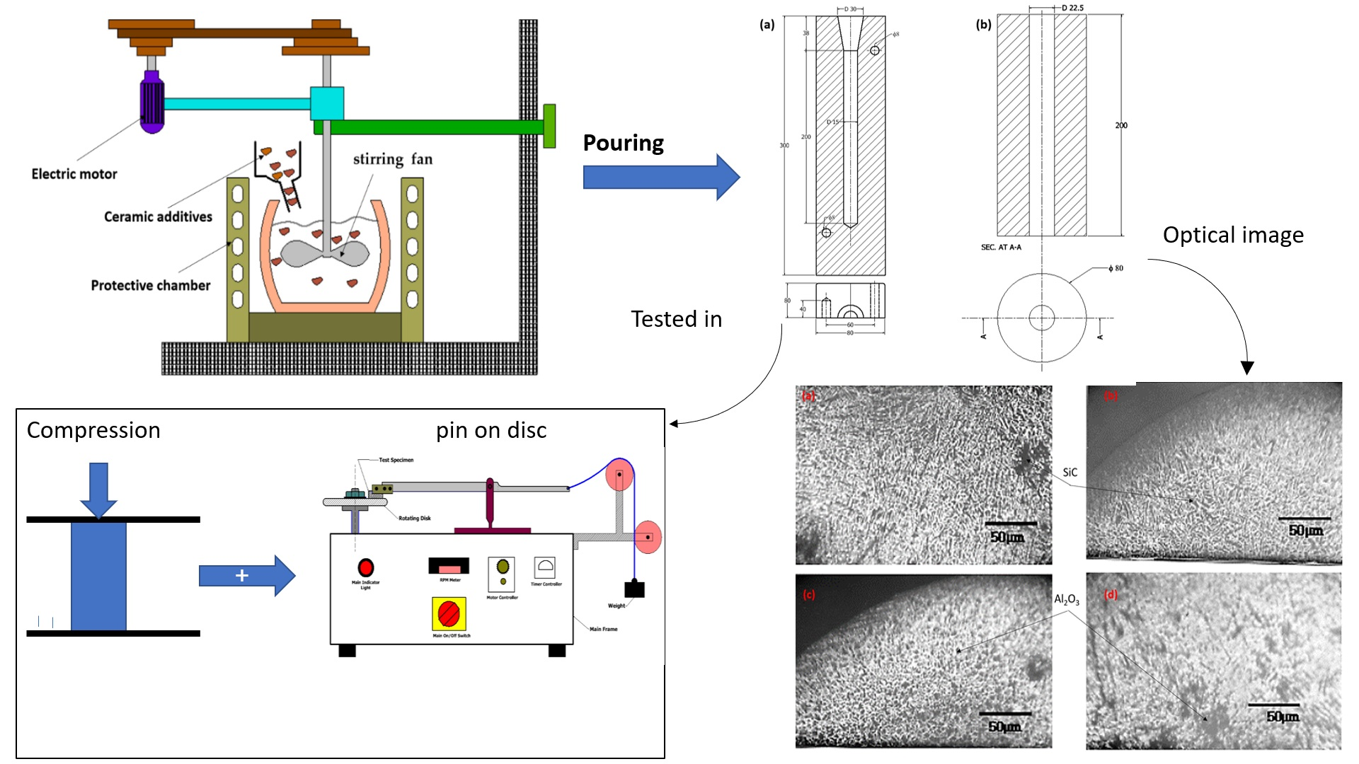
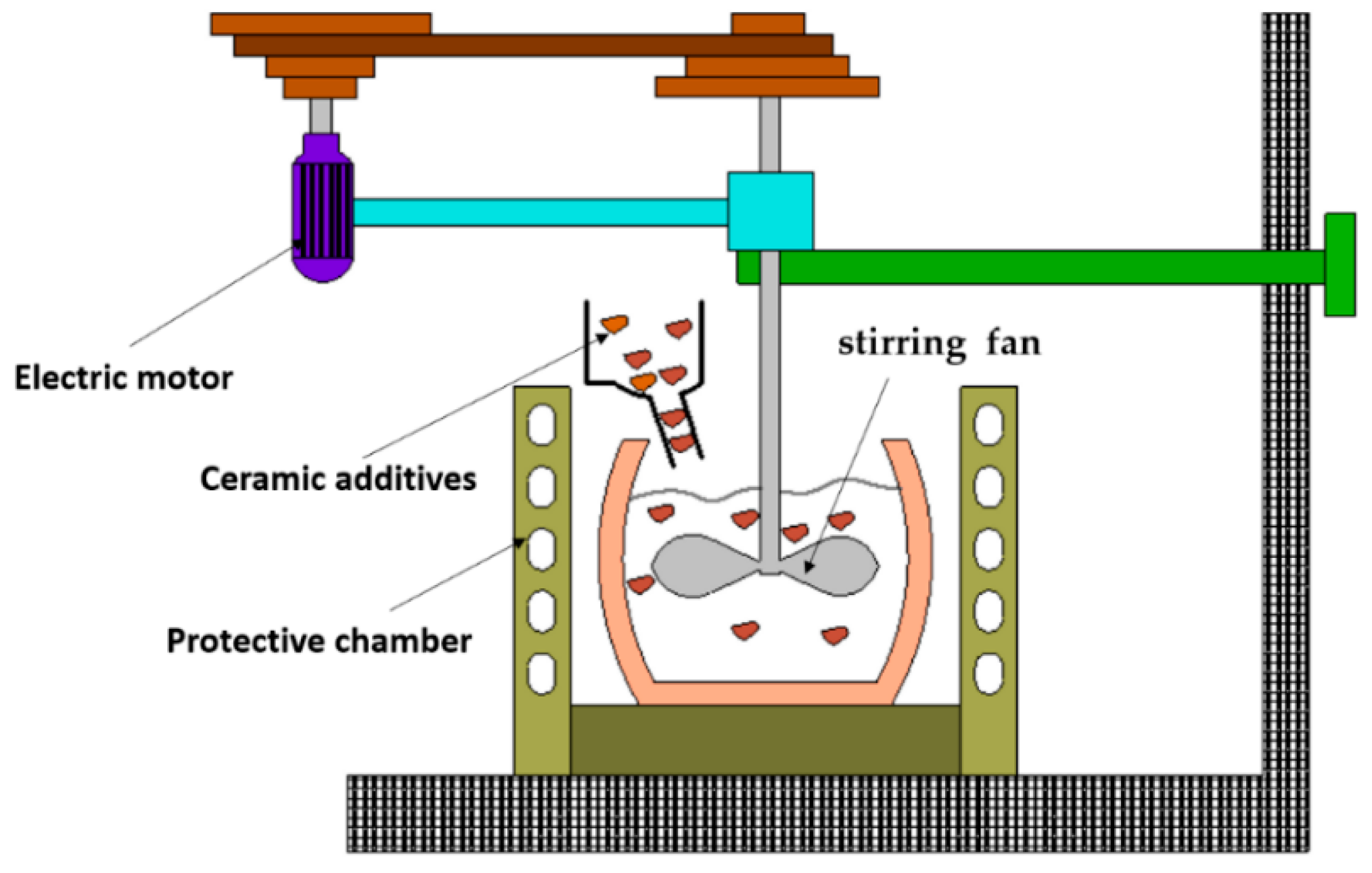
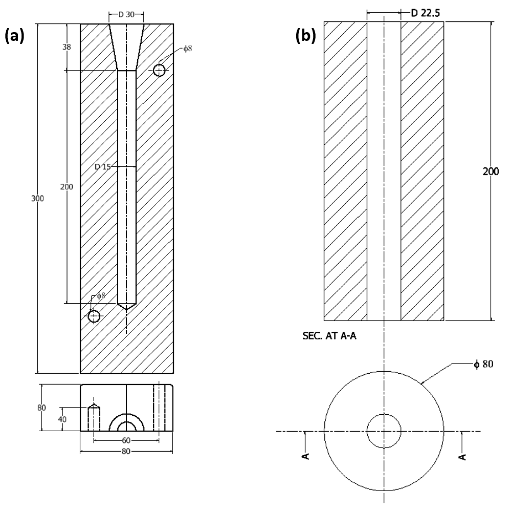
2.1. Stir Casting Process

The aluminum segments were placed in a small ceramic crucible and then placed in an electric furnace with a maximum heating temperature of 1500 °C. The metal was heated to 650 °C. The molten metal was kept at this temperature for 2 h to achieve sufficient homogeneity and solubility [22]. This temperature was above the melting temperature of 580 °C [23]. This temperature was chosen to allow enough time to mix the ceramic additives— alumina Al2O3 and silicon carbide SiCp particles (supplied by El-Gomhouria for Medicines and Medical Supplies, Cairo, Egypt) (Swith a size of almost 40–60 µm—based on heat and mass transfer criteria [24]. The crucible was then removed from the oven and placed in the chamber of the electric mixer (see Figure 1), and the agitator was switched on while the ceramic additives were poured in. The electric mixer was made so that the metal did not splash out during the mixing and stirring process. To prevent a large temperature loss, the ceramic fan was preheated to the same temperature, and the ceramic additives were added to the furnaces to achieve the same temperature of the molten metal. The stirring process took less than 30 s, and then the crucible was poured into the molds. There were two types of molds: H13 Steel alloy of 24.3 W/m.K thermal conductivity and of 0.460 J/g-°C specific heat [25] (Figure 2a) and synthetic graphite (petroleum coke, needle coke, coal pitch, etc.) of 121.1 W/m.k thermal conductivity [26] and of 1.732 J/g °C specific heat [27] (Figure 2b). The castings produced were like the aluminum alloy without any additives (0%), while the Al2O3 and SiC particles were added at 0.5 wt.%, 1 wt.%, 2 wt.%, 3 wt.%, 4 wt.%, and 8 wt.%. It is known that these ceramic additives do not dissolve in the aluminum matrix due to the large differences between melting temperature and density; therefore, the cast product can be called a metal matrix composite [14,28,29]. The cast products had a cylindrical shape of 238 mm × 15 mm for casting in a steel mold and 200 mm × 22.5 mm for casting in a graphite mold.

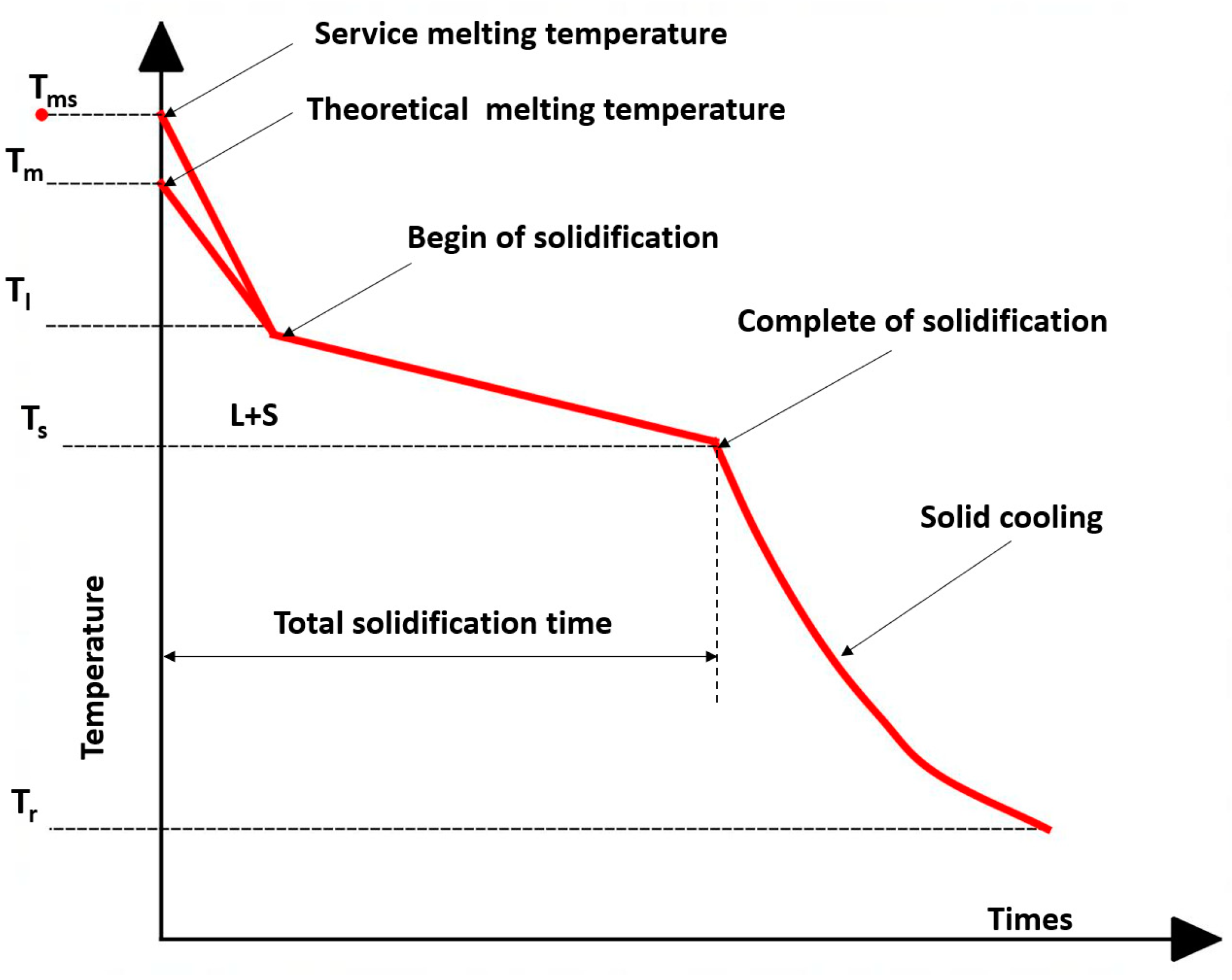
2.2. Heat Loss Analysis

The mechanism of heat transfer during casting depends on the solidification process, the cast metal, and the thermal radiation [30]. These dynamics can be explained by the cooling curve shown in Figure 3. The heat loss during the casting process up to Tl, known as the cooling temperature of the liquid or the beginning of solidification, is mainly due to the turbulent flow in the molten metal to compensate for the longer time needed for mixing the additives and the stirring process; this point is smaller than Tms. The rate of solidification in this range is linear, and the amount of heat is minimal. Solidification begins on contact with the molds at Tl, then continues gradually until it solidifies completely at temperature Ts. The castings are left in the molds until they have cooled completely to room temperature Tr. This normalizes the grain size of the product in the molds, and the boundary conditions are as homogeneous as possible. The solidification process progresses over time. The time at which the temperature of the molds rises significantly to the maximum temperature is the same as when the molten metal reaches the liquidus point. Therefore, a thin layer forms over the outer casting surface, and then the metal shrinks and an air gap is interrupted between the mold and the metal.

Thermal Analysis

Casting of aluminum involved moving the molten metal from the furnace to the mold through a refractory casting crucible; during this operation, the heat was lost into the atmosphere, the crucible during the stirring operation, and even through the casting mold [31]. The heat loss caused by contact with the crucible and the mold can be calculated using Fourier’s law in one dimension:
T t = α 2 T y 2
where T is the temperature in metal 650 °C and y isdisplacement through the mold depth. Using the boundary conditions on the inside of crucible and mold that are the same as the metal, therefore, we can set y = 0 and T (0, t) = T, y = − , T ( ) = Ts, whereas the heat flux at the interface between the wall of the crucible and mold [31] is
q 0 , t t = k T 0 ,   t y
By solving Equation (1) with respect to the derivation of Equation (2), the heat flux P can be calculated in watts using Equation (3) as follows:
P = k ρ c p π × t A T T s
where k is the thermal conductivity of the ceramic refractory for the crucible or for the mold material (graphite, or steel), and c p is specific heat. A is the surface area normal to the direction of heat transfer and can be calculated as follows:
A = s   2 h + b
where s is distance per second of metal flow (m), h is the metal depth, and b is crucible or mold width. For a mass m molten metal, the energy can be expressed by rewriting Equation (3) as follows:
P = m × c p × T
Hence, the temperature gradient or loss T in transferring the molten metal from furnaces to the crucible or mold cavity is as follows:
T = Pm × cp
For the heat reduction due to radiation, the temperature loss can be calculated using the radiation as follows [31]:
P = ε × σ × A T 4 T o 4
where ε is the emissivity (0.09 to 0.24) for the aluminum alloy 6061 [32] and σ is Stefan Boltzmans constant [33,34], 5.67 × 10⁻⁸ (W/mK). Then, the temperature loss can be calculated using Equation (8):
T = ε × σ × b T 4 T o 4 m × c p
where T is now the temperature reduction per meter due to radiation.

2.3. Sample Perspiration

The cast products taken from the molds were cut into nominal dimensions using the Turing process. The nominal dimensions were 12 mm × 200 mm for the specimens cast in steel molds, while they were 180 mm × 20 mm for those cast in graphite molds. These specimens were cut into three equal segments along the entire length of the specimen. This technique reduced the inhomogeneity and percentage error when repeating the test, as it was the same sample and the segregation effect was low, as cited in a previous study by Hassan et al. [14,29].

2.4. Compression Test

The compression test was carried out according to the ASTM E9 standard [35] at room temperature. This test is used to measure the compressive strength, Young’s modulus, and percentage deformation of the cast product. The test was conducted using a universal testing machine (Model WDW-100, Jinan Victory Instrument Co., Ltd., Jinan, China) [36] with a load capacity of 100 kN and a controlled speed of 5 mm/min. The load values were recorded with the load indicator, while the deformation was measured with a 0.005 mm dial gauge attached to the moving platen of the machine. The ends of the specimens were supported on two hardened parallel steel plates. These two parallel plates, conforming to the ASTM E9 standard [35], were used to ensure even distribution of the loads and to prevent tipping of the head, which can occur during the test. The test was performed dry and without lubrication between the plate and the specimen. The test was continued until the optical crack imitation appeared on the surface of the specimen. The sample height was measured before and after the test, with a 0.05 mm vernier. The test was performed on all samples with and without additives, cast in both molds. The specimens were, as mentioned above, short specimens with a high thickness ratio (h/d ≈ 0.8) according to the ASTM E9 standard [35].

2.5. Hardness Test

The Vickers hardness test was conducted in accordance with ASTM E384-10 [37]. The test was performed with a universal hardness testing machine (Zwick/ZHU 187.5, ZwickRoell, Ulm, Germany) [26]. A diamond-shaped, square, pyramid indenter was pressed into the surface under a uniform load. The load was maintained for (15) seconds to achieve a uniform condition, and then the indenter was removed. The surface of the specimen should be prepared by polishing in two steps before testing. The first step is polishing with medium-grit emery paper (1000) to remove all rough surface imperfections, and the second step is to use very fine silicon carbide emery paper (2000) to polish the surface like a mirror. Then, the surface is etched with sulphuric acid H2SO4 for about 1 min. After that, the samples are ready for the Vickers hardness test. The specimens taken from the three previously cut positions were 5 mm × 12 mm and 5 mm × 20 for the specimens cast in steel and graphite molds, respectively.

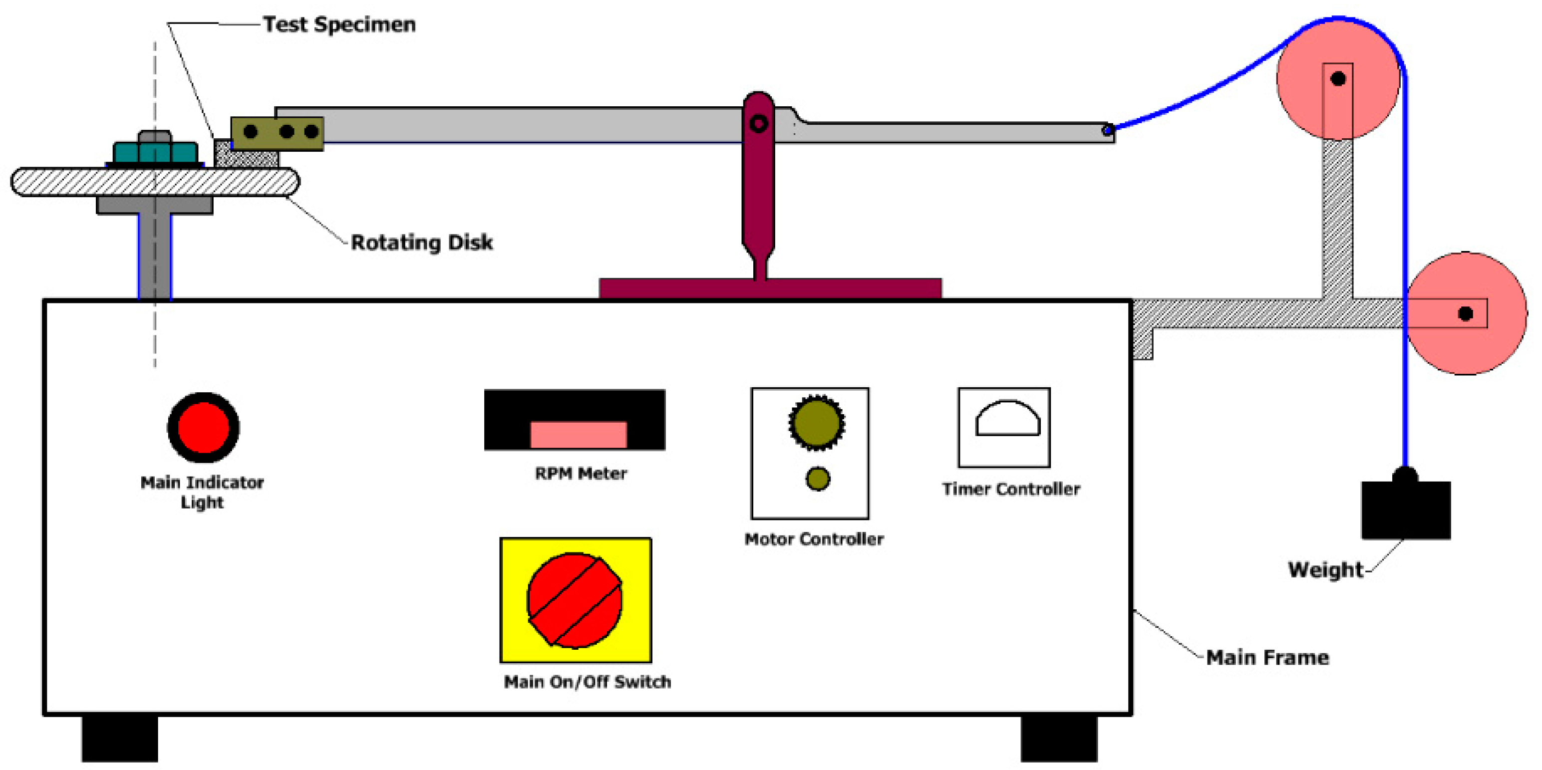
2.6. Pin-on-Disc Wear Test

The wear test is performed with a pin on a disc according to the ASTM G99-05 standard [38]. The test was performed on all cast products. Figure 4 shows a general view of the wear test machine (SSITOM-012-Pin On Disc Wear Apparatus, Saini Scientific Industry, Haryana, India) [14]. It consists of a horizontal steel disc with an inner diameter of 50 mm, an outer diameter of 100 mm, and a thickness of 2 mm, which rotates and is driven by a variable-speed motor. A specimen holder connected to the loading lever and pressed against the rough counter surface is used to hold the specimen. The load is applied with a dead weight of 1600 g at a 3.5 m/min and 5 m/min linear speed at 5 min contact time. The surface of the sample was polished with 1000-grit emery paper to remove any unevenness or impurities. The initial weight was then measured with an accuracy of 0.001 g, and the sample was fixed in the play as a 12 mm diameter pin. In addition, 80-grit emery paper with a surface roughness of 1.80 × 10⁻⁶ was glued to the opposite side of the steel disc with epoxy glue; then, the pin (the sample surface) was contacted in a dry state and not lubricated. The motor speed was 400 rpm.

3. Results and Discussion

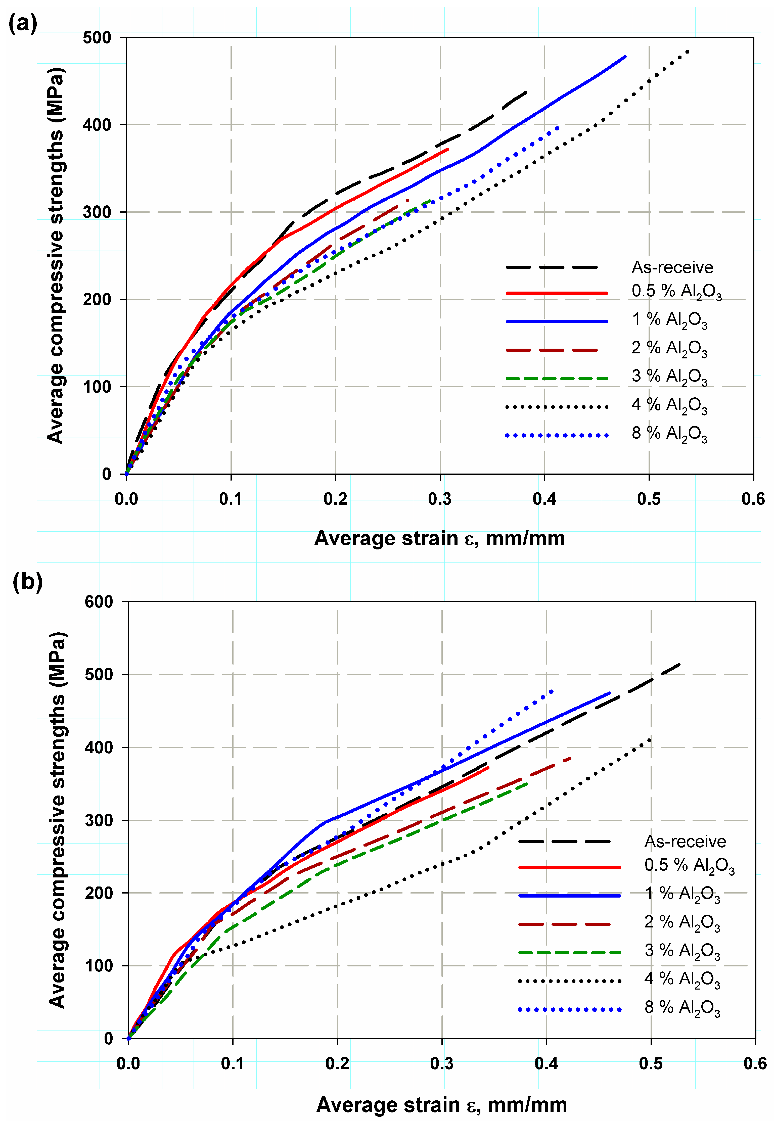
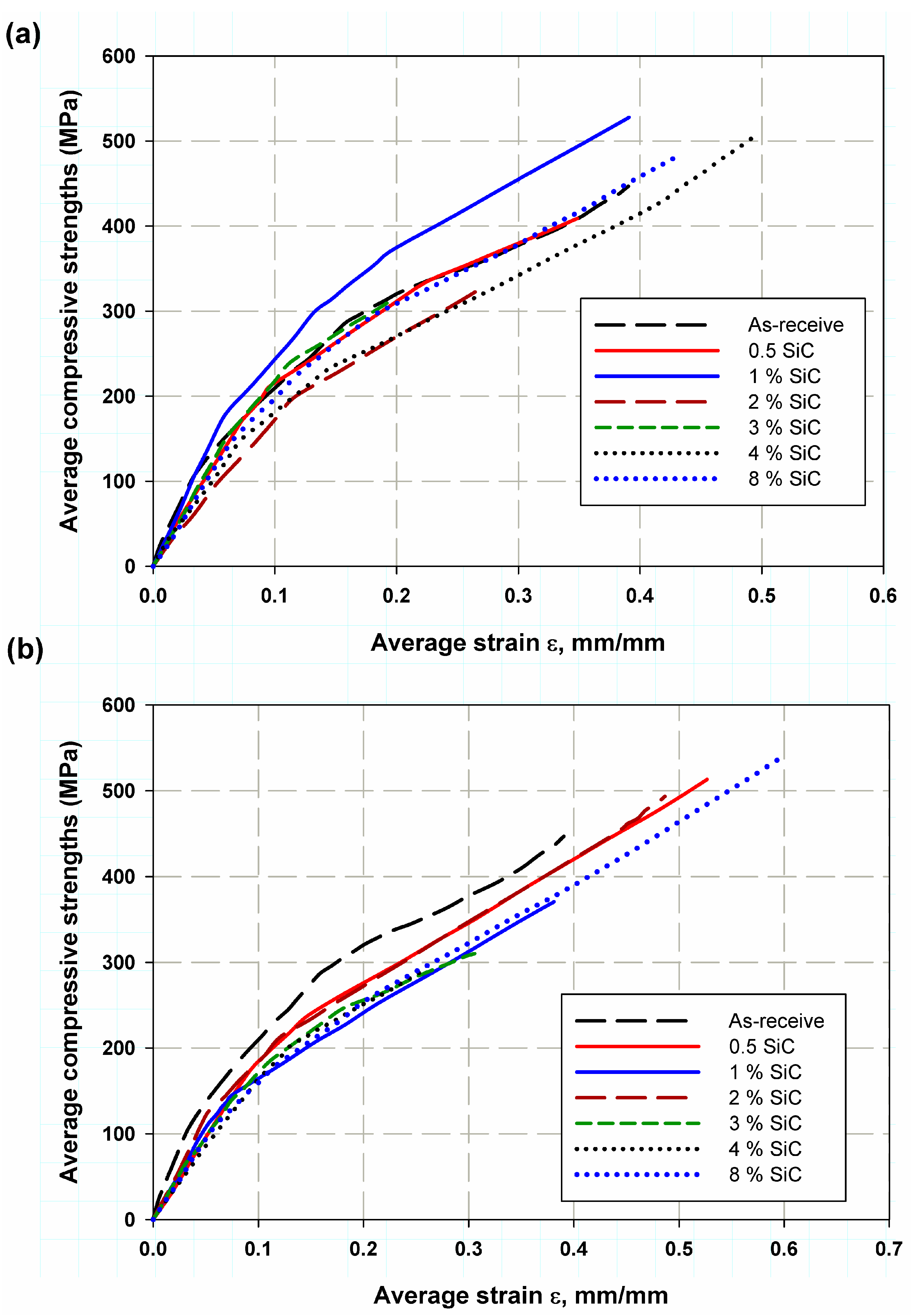
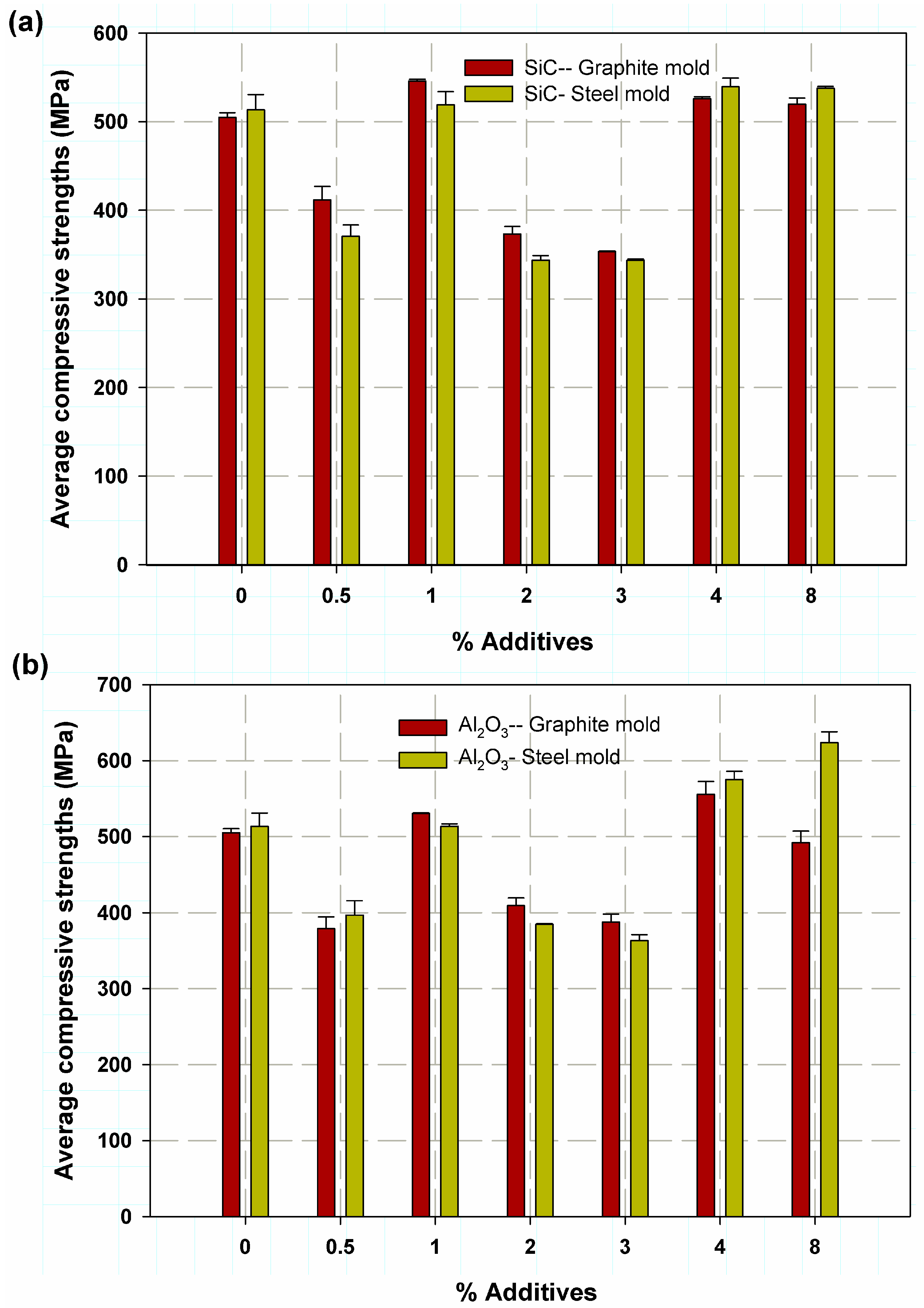
3.1. Compressive Strength
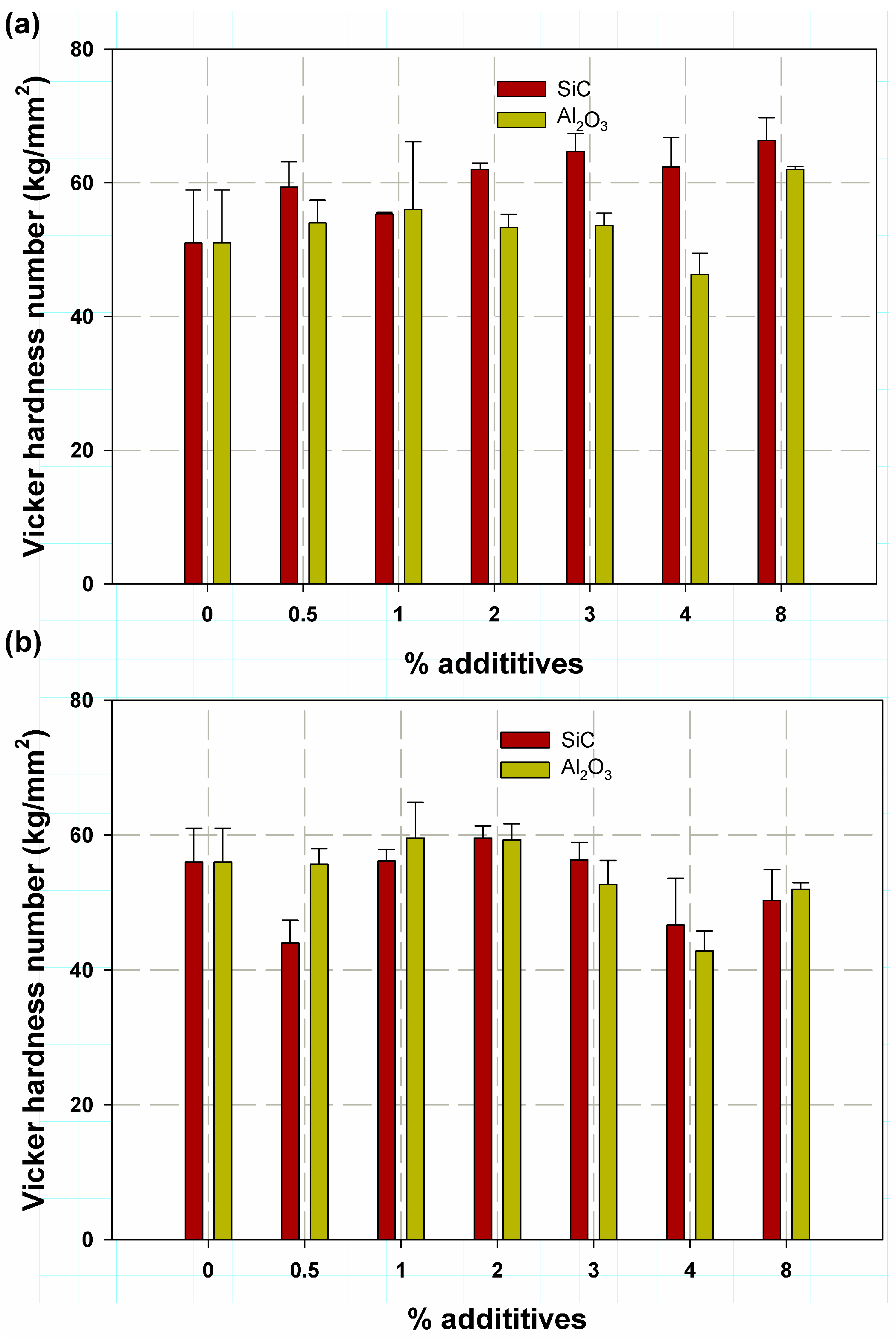
The average compressive strength as a function of deformation stress is shown in Figure 5 and Figure 6. It was found that the deformation strain increases with increasing additions for Al2O3 cast in graphite mold (Figure 5a). This was true for specimens with 1, 4, and 8 wt.% Al2O3. In addition, these three specimens had a higher compressive strength. The Young’s moduli are close to each other, the curve is almost smooth, and no catastrophic failure occurred. The strength reached almost the maximum values of over 500 MPa for the specimens without Al2O3, while it decreased with increasing Al2O3 content in the steel mold (see Figure 5b), which can be attributed to deformation. The values of the Young’s moduli were almost the same. This is because the alloy cast in a steel mold has a lower specific heat and a higher emission coefficient ε, so the heat transfer is higher and faster for steel castings than for samples cast in a graphite mold. The higher cooling rate resulted in refinement and smaller grain size [16], while in graphite molds and ceramic molds, which are characterized by higher specific heat and thus lower emission coefficient, heat transfer takes longer, resulting in the coarsening of the grains. A fine grain size is preferred to increase the strength and reduce voids and defects. Figure 6a shows the compressive strength of composite aluminum embedded with SiC particles casted in a graphite mold. The strength values and deformation strains for 0.5, 3, and 8 wt.% Si C were nearly the same; with the as-received aluminum alloy (without additives), the deformation strain reached a maximum of 0.5 for 8 wt.% SiC and a minimum for 2 wt.% SiC. For composite metal casted in steel mold (Figure 6b), it was found to increase in strength and deformation strain with the increase in the wt.% of SiC additives for the aluminum alloy matrix. However, the strength and deformation strain decreased for 1 wt.% and 3 wt.% Si C, due to segregation in the alloy, which cannot be eliminated completely in the casting production technique [14,29]. More concentration appears on the curve, and it was found that the curve has two sloped regions, an elastic slope followed by another slope over the plastic zone, as clearly seen in specimens of 1 wt.% and 4 wt.% Al2O3 casted in steel mold (see Figure 5b and Figure 6b). Table 1 and Table 2 list the exact values of the average of three compressive tests of Al-Mg-Si alloy composed of ceramic additives casted in graphite and steel molds, respectively. In Table 2, the specimens gave high average compressive values for 1 wt.% Al2O3 of 530.37 MPa with a standard Deviation SDV 1.06 and a maximization as 55.45 MPa with SDV 29.12 MPa at 4 wt.% Al2O3 when casted in the graphite mold. In addition, it was 525.98 MPa with SDV 3.37 MPa for 1 wt.% SiC and 545.92 MPa with SDV 3.7 MPa at 4 wt.% SiC when also casted in graphite molds. The lowest percentage error was 0.61 and 0.9 for specimens with 1 wt.% Al2O3 and 3 wt.% SiC, which indicates the stability of the test procedure and its repeatability. The highest value of the height reduction was 54.4% for the specimen containing 4 wt.% SiC particles; therefore, the ductility for this specimen and the deformation ability was increased and enhanced, which is the reason behind the higher compressive properties with a composite containing Si C and a symmetry between the alloy internal element over 0.5 wt.% Si (see Figure 7a,b). Table 2 lists the effect of the steel mold on the casting compressive strength; it was found that the maximum compressive strength was 623.53 MPa with an SDV of 24.99 MPa for 8 wt.% Al2O3 particles. Then, asecond degree was a specimen filled with 4 wt.% Al2O3 as 574.77 MPa with an SDV of 19.08 MPa, whereas for SiC particles, the reduction in strength in terms of the maximum values walso at 4 wt.% SiC with 539.46 MPa and an SDV of 16.3 MPa, whereas, in the second grade, the 8 wt.% SiC had an average value of compressive strength of 537.65 and an SDV of 3.59 MPa. The higher ductility was achieved with a 4 wt.% of SiC of 59%. Although the casting in steel mold was given higher values of compressive properties, the stability of the tests was smaller than that of casting in the graphite mold, because the % error of the specimen casted in steel had a higher value, and the minimum value was 1.04 for 4 wt.% Al2O3. Then, in the second grade, the value was 1.49 for 3 wt.% SiC particles (see Figure 7a,b). Figure 8 shows an optical image to illustrate the distribution of the particle through the Al-Si-Mg alloy matrix. It was observed that there was a region with a higher concentration than other regions. The surface patterns wer finer for the specimen casted in the steel mold, as shown in Figure 8a,c, whereas some coarsening was observed in the specimen casted in graphite molds, as shown in Figure 8b,d. The load was transmitted between the MMC by the interfacial region between the Al-Si-Mg alloy and the SiC and Al2O3 additives [39,40]. Therefore, the increase in compressive strength with the additives occurs because these additives function as a secondary feature in the matrix phase, which resists the progressive deformation in the metal matrix [4,40]. While the separation at the interface between the Al-Si-Mg alloy and theceramic additives (SiC and Al2O3) was the major failure mechanism in the recasting methods [7], the failure mechanism related to the alloy without the additive depends on the Si element, which was homogeneously distributed in the aluminum matrix; therefore, it cleaved to form microcracks [35]. Therefore, the separation at the interfaces formed ductile cracks ahead of microcracks and then interconnected by localized shear bands deformed in the aluminum matrix. These results were similar to those of Nikhil et al. [41], where the graphite was used to strengthen the aluminum matrix composite. It was reported that the strength enhancement due to the reinforced phase acts as if they are a load barrier [7,13].

3.2. Hardness Test

The change in Vickers hardness at different Al2O3 weight percentages is shown in Figure 9a. It was found that there are two factors. The first factor, Vickers hardness, was higher for 0 wt.%, 0.5 wt.%, 1 wt.% and 2 wt.%, and 1 wt.% and 2 wt.% Al2O3 cast in steel molds, while for the second issue, for 3 wt.%, 4 wt.% and 8 wt.% Al2O3, the trend was towards higher hardness. For the % Al2O3, the trend changed: the hardness was higher for Al2O3 cast in a graphite mold. This is because a cooling rate in the graphite mold is allowed due to the higher specific heat of graphite and the increasing amount of alumina, which has a lower density and takes more time to segregate through the molten metal, so it is deposited more on the surface, whereas with the small amount, it is not saturated over the entire surface of the samples [21] (see Figure 8a). The maximum Vickers hardness was 62 kg/mm2 with an SDV of 0.81 kg/mm2 and a % error of 0.47 for 8 wt.% Al2O3 cast in a graphite mold, and 59.5 kg/mm2 with an SDV of 9.25 kg/mm2 and a standard % error of 5.33 for 1 wt.% Al2O3 cast in a steel mold. In general, the standard % errors were low; therefore, the test stability was acceptable and good [42]. On the other hand, the effect of SiC particles on Vickers hardness is shown with the mold in Figure 8b. Two observations were made: first, the increase in SiC particles increased the Vickers hardness for 1 wt.% to 8 wt.%, and second, the hardness in the graphite mold was higher than that in the steel mold for all wt.%. This is due to the homogeneity of the Si addition in the Al-Si-Mg alloy, but also due to the graphite mold with SiC, as the carbon combined with graphite increased the grain size due to the low cooling rate. The maximum Vickers hardness was 66 kg/mm2 for a composite with 8 wt.% SiC cast in a graphite mold with an SDV of 5.9 kg/mm2 and a minimum standard error of 3.4. The maximum hardness was 56.33 kg/mm2 for a composite with 3 wt.% SiC cast in a steel mold with an SDV of 4.49 kg/mm2 and a lower standard error of 2.59, again indicating the reliability of the test procedures. The ceramic additives give some shielding to the aluminum matrix from plastic deformation; therefore, the strain energy stored increased, and the hardness improved [43,44]. However, the specimens casted in graphite with Al2O3 reinforcement decreased as in Seah et al. [45]. This could be attributed to the graphite molds, permitting graphite elements to diffuse through the aluminum matrix and therefore causing the material ductility to increase [46]; therefore, it was easily deformed with the hardness indentor [13], whereas with the SiC particles, it was a little higher.

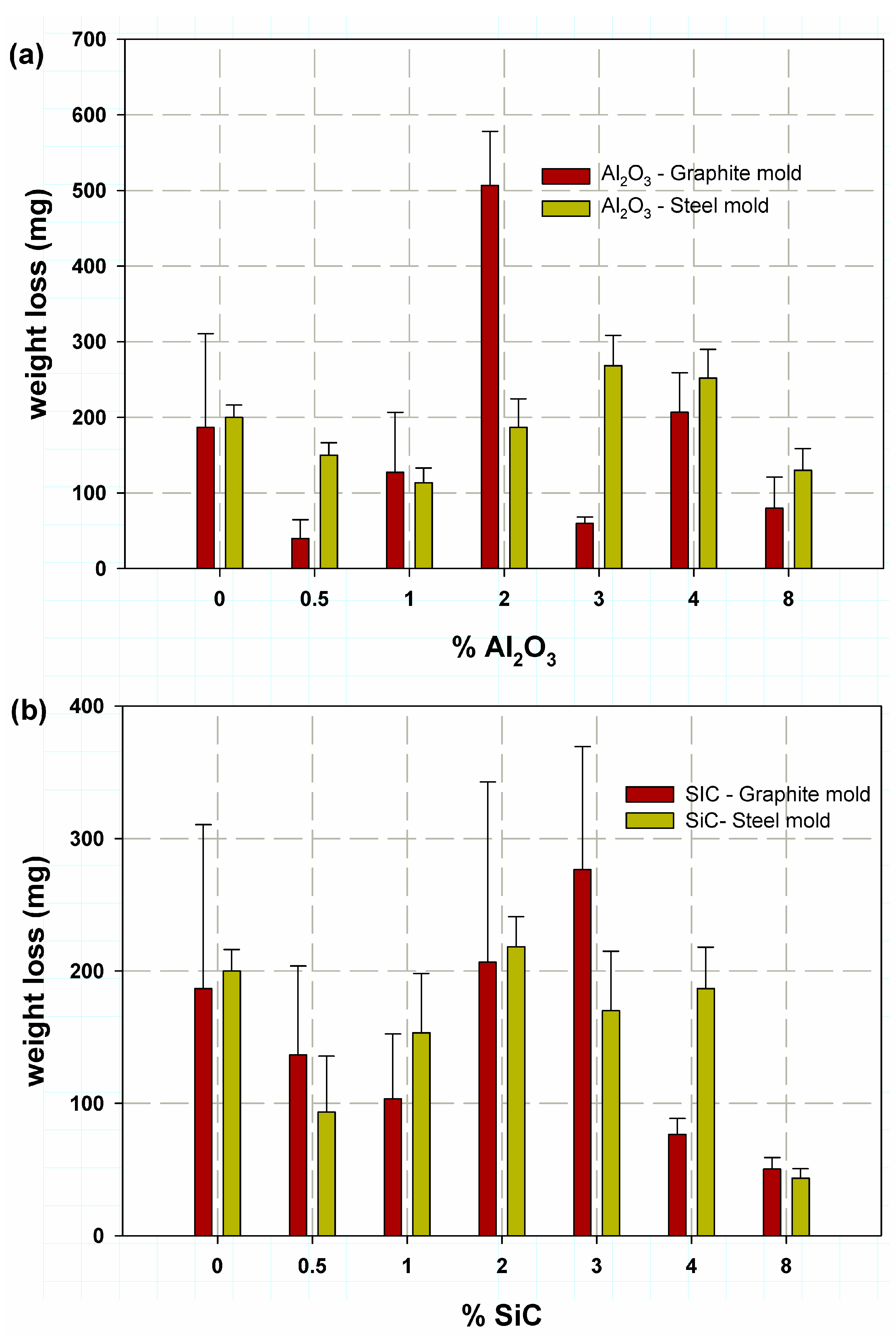
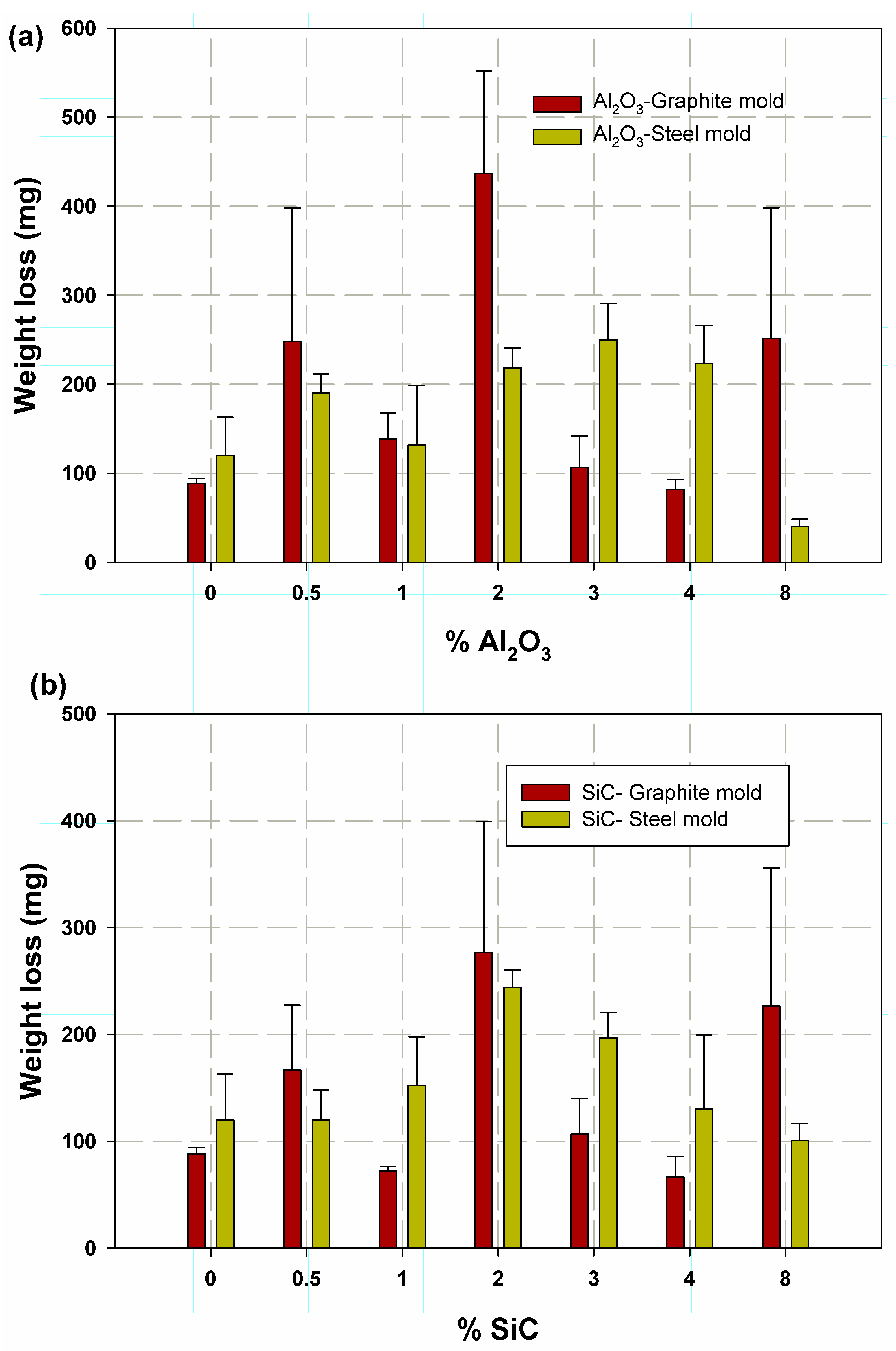
3.3. Wear Properties

First of all, it is well-known that wear tests involve a variety of individual concepts, and many factors can influence material performance [47]. Therefore, various trends were observed. In general, it was found that most percentage standard errors were high because many factors affect the wear test, such as the type of interfaces, surface finish of the material, types of material, machine speed, vibration-specific heat, and thermal conductivity of the material. It was found that, in general, casting in a steel mold at a sliding speed of 3.5 m/min (see Figure 10) and 5 m/min (see Figure 11) resulted in a higher wear rate than casting in a graphite mold. This was attributed to the fact that when casting in a graphite mold, a graphite element diffuses through the Al alloy matrix, as high temperatures and good contact favor the diffusion and wettability of the aluminum [48], so graphite acts as a solid lubricant that reduces the effects of wear. In addition, the low cooling rate in graphite molds was the main reason for the coarsening of the grain size of the Al-Si-Mg alloy so that it absorbed some of the shear stress such as dumpers, resulting in a reduction in the wear loss. In contrast, when casting in steel molds, the heat loss is higher due to the higher heat transfer from radiation and the lower specific heat of the steel mold. This higher cooling rate resulted in grain refinement, especially near the mold wall [16]. In Figure 10a and Figure 11a,b, it can be found that the 2 wt.% Al2O3 and SiC almost gave a maximum average weight loss. It was 506.66 mg with an SDV of 123.5 mg and a minimum standard error of 71% for the Al-Si-Mg alloy cast in a graphite mold filled with Al2O3 at a sliding speed of 3.5 m/min (Figure 10a), while it was 436 mg with an SDV of 200 mg and an error of 115.5% error for the alloy filled with Al2O3 also cast in a graphite mold but at a sliding speed of 5 m/min (see Figure 11a). Furthermore, the SiC at 2 wt.% shows the same trend, as the average wear loss was 776.6 mg with an SDV of 212 mg and 122% error, even when cast into a graphite mold. In contrast, the addition of 3 wt.% SiC to the Al-Si-Mg alloy increased the weight loss to a maximum value of 276 mg with an SDV of 160 mg and 92% error when also cast in a graphite mold and at a sliding speed of 3.5 m/min. It was also observed that most Al-Si-Mg alloys filled with SiC particles had a weight loss of less than 200 mg, as SiC reacts with the aluminum according to the reaction shown below, resulting in wettability of the aluminum and an increase in the amount of Si in the aluminum matrix itself [48], while Al4C3 increased the amount of carbon, which acts as a solid lubricant.
3 SiC + 4 Al                                                         Al 4 C 3 + 3 [ Si ]
It was observed generally that the Al-Si-Mg alloy matrix gave higher wear resistance, which was due to the strong bonding between the ceramic additives and the aluminum matrix, which led to less third-body wear during the wear process, as reported in [3,49]. The same results were reported for ceramic particulates inserted through an aluminum matrix carrying most of the shear load of wear action; hence, it effectively protects the matrix alloy matrix from extreme wear loss. It was also similar to that reported with other ceramic additives such as Fe2O3 and B4C, where the wear resistance improves and increases with the ceramic additives. As cited before, the SiC particles and Al2O3 strengthen the aluminum matrix failure due to the separation at the interfaces, which needed larger shear forces due to homogeneity and higher dependability. On the other hand, the wear loss mechanism may be due to the oxide layer formed around the ceramic additives at the interfaces, which may lead to the formation of MgO, which weakens the bonding, as it was not coherent with the matrix phase [50]. Increasing wear loss in the Al2O3 was observed due to a tribo-chemical reaction between alumina particulates and the steel of the machine disc [3], similarly to the study performed by Brown et al. using X-ray diffraction of the wear aspartates generated during wear action [51].

4. Conclusions

Nowadays, metal matrix composites are setting the standard in the majority of industrial sectors. Due to its strength and high corrosion and wear resistance, the Al-Si-Mg alloy has been a competitive and alternative material in the aerospace and automotive industries. With the notably inexpensive stir-casting method, an Al-Si-Mg alloy composite material with various weight percentages of SiC and Al2O3 particles was prepared. The aluminum alloy loaded with 8 percent Al2O3 by weight showed a maximum compressive strength of 623.53 MPa. The compressive strength of the alloy with the added Al2O3 particles cast in a steel mold was 21% higher than that of the Al-Si-Mg alloy. Additionally, the aluminum alloy loaded with 8 percent SiC particles by weight and cast in a graphite mold increased the Vickers hardness by 29% to a maximum value of 66 kg/mm2. However, casting in graphite mold with SiC particles was favored and is recommended owing to the involvement of Si from the SiC, graphite production from the graphite mold, and segregation of the alloy itself. Additionally, wear resistance was typically boosted by the inclusion of particles. When cast in a graphite mold, the particles in the Al-Si-Mg alloy were more evenly dispersed. On the other hand, because of the rapid cooling, the compressive strength rose when the material was cast in a steel mold. The present hypotheses were achieed through the ability to apply heat treatments to casting products during the casting process, which reduced time and expenses. An MMC with ceramic additives may be formed from an Al-Si-Mg alloy using the suggested stir-casting sequence method with a lower segregation percentage. Additionally, it had a limitation whereby MgO, the primary cause of material embrittlement, formed as a result of the creation of an oxidation layer surrounding the ceramic additions that reacted with the alloy’s Mg. It is suggested that future research thoroughly examine the impact of ceramic additives at the micro-structure level using the wet wear test, SEM, and EDX analysis.

Author Contributions

Conceptualization, M.Y.A., M.K.H., and A.F.M.; methodology, M.Y.A. and A.F.M.; software, M.Y.A. and M.K.H.; validation, A.H.B. and M.K.H.; formal analysis, M.Y.A., M.K.H., and A.H.B.; investigation, M.Y.A., M.K.H., and A.F.M.; resources, A.H.B.; writing—original draft preparation, M.Y.A., M.K.H., B.M.F., H.M.A.E.-A., and A.F.M.; writing—review and editing, M.Y.A. and A.F.M.; supervision, M.K.H., B.M.F., H.M.A.E.-A., and M.Y.A.; project administration, M.Y.A. and A.H.B.; Editing, A.H.B. All authors have read and agreed to the published version of the manuscript.

Funding

This research received no external funding.

Institutional Review Board Statement

Not applicable.

Informed Consent Statement

Not applicable.

Data Availability Statement

The data presented in this study are available on request from the corresponding author.

Conflicts of Interest

The authors declare no conflict of interest.

References

  1. Biswal, S.R.; Sahoo, S. A Comparative analysis on physical and mechanical properties of aluminum composites with alo and ws reinforcement. In Recent Advances in Mechanical Engineering; Springer: Berlin/Heidelberg, Germany, 2023; pp. 597–603. [Google Scholar]
  2. Sujatha, S. Valuation of Strength Enhancement in Heat Treated SiC Nanoparticles Reinforced 2024 Aluminum Alloy Metal Matrix Composites Using FEA. Ph.D. Thesis, College of Engineering, JNT University, Hyderabad, India, 2005. [Google Scholar]
  3. Caracostas, C.A.; Chiou, W.A.; Fine, M.E.; Cheng, H.S. Tribological properties of aluminum alloy matrix TiB2 composite prepared by in situ processing. Metall. Mater. Trans. A 1997, 28, 491–502. [Google Scholar] [CrossRef]
  4. Mummoorthi, D.; Rajkumar, M.; Kumar, S.G. Advancement and characterization of Al-Mg-Si alloy using reinforcing materials of Fe 2 O 3 and B 4 C composite produced by stir casting method. J. Mech. Sci. Technol. 2019, 33, 3213–3222. [Google Scholar] [CrossRef]
  5. Geng, R.; Jia, S.Q.; Qiu, F.; Zhao, Q.L.; Jiang, Q.C. Effects of nanosized TiC and TiB2 particles on the corrosion behavior of Al-Mg-Si alloy. Corros. Sci. 2020, 167, 108479. [Google Scholar] [CrossRef]
  6. Duraipandian, M. Effects of Fe 2 O 3 and B 4 C Addition on the Mechanical Properties and Corrosion Resistance of Al–Mg–Si Alloy in 3.5% Brine Solution. Met. Mater. Int. 2021, 27, 1506–1518. [Google Scholar] [CrossRef]
  7. Lee, S.; Suh, D.; Kwon, D. Microstructure and fracture of SiC-particulate-reinforced cast A356 aluminum alloy composites. Metall. Mater. Trans. A 1996, 27, 3893–3901. [Google Scholar] [CrossRef]
  8. Auras, R.; Schvezov, C. Wear behavior, microstructure, and dimensional stability of as-cast zinc-aluminum/SIC (metal matrix composites) alloys. Metall. Mater. Trans. A 2004, 35, 1579–1590. [Google Scholar] [CrossRef]
  9. Kumar, G.V.; Panigrahy, P.P.; Nithika, S.; Pramod, R.; Rao, C.S. Assessment of mechanical and tribological characteristics of Silicon Nitride reinforced aluminum metal matrix composites. Compos. Part B: Eng. 2019, 175, 107138. [Google Scholar] [CrossRef]
  10. Padmavathi, K.; Ramakrishnan, R. Tribological behaviour of aluminium hybrid metal matrix composite. Procedia Eng. 2014, 97, 660–667. [Google Scholar] [CrossRef]
  11. Krishna, M.V.; Xavior, A. An investigation on the mechanical properties of hybrid metal matrix composites. Procedia Eng. 2014, 97, 918–924. [Google Scholar] [CrossRef]
  12. Oyedeji, O.E.; Dauda, M.; Yaro, S.A.; Abdulwahab, M. Characterization of Al-Mg-Si Alloy Reinforced with Optimum Palm Kernel Shell Ash (PKSA) Particle and its Consequence on the Dynamic Properties for Aerospace Application. 2021. Available online: https://assets.researchsquare.com/files/rs-795334/v1/7d9afc38-d01a-4da0-baf7-0beb6f35b473.pdf?c=1631888198 (accessed on 12 January 2023).
  13. Nagaral, M.; Auradi, V.; Bharath, V.; Patil, S.; Tattimani, M.S. Effect of micro graphite particles on the microstructure and mechanical behavior of aluminium 6061 (Al-Mg-Si) alloy composites developed by novel two step casting technique. J. Met. Mater. Miner. 2021, 31, 38–45. [Google Scholar] [CrossRef]
  14. Mohamed, K.; Hassan, Y.M. Abu El-Ainin H, Improvement of Al-6061 alloys mechanical properties by controlling processing parameters. Int. J. Mech. Mechatron. Eng. IJMME-IJENS 2012, 12, 14–18. [Google Scholar]
  15. Seong, H.; Lopez, H.; Rohatgi, P. Microsegregation during solidification of graphitic fiber-reinforced aluminum alloys under external heat sinks. Metall. Mater. Trans. A 2007, 38, 138–149. [Google Scholar] [CrossRef]
  16. Liang, G.; Ali, Y.; You, G.; Zhang, M.X. Effect of cooling rate on grain refinement of cast aluminium alloys. Materialia 2018, 3, 113–121. [Google Scholar] [CrossRef]
  17. Emrani, V.; Zandi, M.; Asadollahzadeh, H. The Inhibitory Effect of Amoxicillin on Aluminum Corrosion in a Gel Electrolyte. Int. J. Electrochem. Sci. 2022, 17, 2. [Google Scholar] [CrossRef]
  18. Abdellah, M.Y. Essential work of fracture assessment for thin aluminium strips using finite element analysis. Eng. Fract. Mech. 2017, 179, 190–202. [Google Scholar] [CrossRef]
  19. Cheng, J.; Zhang, Z.; Dong, X.; Song, G.; Liu, L. A novel post-weld composite treatment process for improving the mechanical properties of AA 6061-T6 aluminum alloy welded joints. J. Manuf. Process. 2022, 82, 15–22. [Google Scholar] [CrossRef]
  20. Gao, J.; Cao, Y.; Lu, L.; Hu, Z.; Wang, K.; Guo, F.; Yan, Y. Study on the interaction between nanosecond laser and 6061 aluminum alloy considering temperature dependence. J. Alloys Compd. 2022, 892, 162044. [Google Scholar] [CrossRef]
  21. Abdellah, M.Y. Ductile Fracture and S–N Curve Simulation of a 7075-T6 Aluminum Alloy under Static and Constant Low-Cycle Fatigue. J. Fail. Anal. Prev. 2021, 21, 1476–1488. [Google Scholar] [CrossRef]
  22. Anyalebechi, P.N. Analysis of the effects of alloying elements on hydrogen solubility in liquid aluminum alloys. Scr. Metall. Et Mater. 1995, 33, 1209–1216. [Google Scholar] [CrossRef]
  23. Kaufman, J.G. Introduction to Aluminum Alloys and Tempers; ASM International: Almere, The Netherlands, 2000. [Google Scholar]
  24. Middleman, S. An introduction to Mass and Heat Transfer: Principles of Analysis and Design; John Wiley & Sons: Hoboken, NJ, USA, 1997. [Google Scholar]
  25. Material Properties Data. Available online: https://www.matweb.com/search/datasheet_print.aspx?matguid=e30d1d1038164808a85cf7ba6aa87ef7 (accessed on 12 January 2023).
  26. Available online: http://www.newmaker.com/product-1000-Hardness-Testing-Instrument-Zwick-ZHU-187,5.html (accessed on 12 January 2023).
  27. Available online: https://www.matweb.com/search/DataSheet.aspx?MatGUID=3f64b985402445c0a5af911135909344 (accessed on 30 January 2023).
  28. Kaczmar, J.; Pietrzak, K.; Włosiński, W. The production and application of metal matrix composite materials. J. Mater. Process. Technol. 2000, 106, 58–67. [Google Scholar] [CrossRef]
  29. EI-Aini, H.A.; Mohammed, Y.; Hassan, M. Effect of mold types and cooling rate on mechanical properties of Al alloy 6061 within ceramic additives. In Proceedings of the Second International Conference of Energy Engineering, ICEE-2, Aswan, Egypt, 27–29 December 2010. [Google Scholar]
  30. Gowsalya, L.A.; Afshan, M. Heat transfer studies on solidification of casting process. In Casting Processes and Modelling of Metallic Materials; IntechOpen: London, UK, 2021. [Google Scholar]
  31. Kastebo, J.; Carlberg, T. Temperature measurements and modeling of heat losses in molten metal distribution systems. In Proceedings of the Light Metals 2004: Technical Sessions Presented by the TMS Aluminum Committee at the 133rd TMS Annual Meeting, Charlotte, NC, USA, 14–18 March 2004. [Google Scholar]
  32. Infrarde, E.A.Z.Z.U.; Termografije, E. Emissivity of aluminium alloy using infrared thermography technique. Mater. Tehnol. 2018, 52, 323–327. [Google Scholar]
  33. Kalinin, M.; Kononogov, S. Boltzmann’s constant, the energy meaning of temperature, and thermodynamic irreversibility. Meas. Tech. 2005, 48, 632–636. [Google Scholar] [CrossRef]
  34. Landsberg, P.T.; De Vos, A. The Stefan-Boltzmann constant in n-dimensional space. J. Phys. A Math. Gen. 1989, 22, 1073. [Google Scholar] [CrossRef]
  35. ASTM E9-09; Standard Rest Methods of Compression Testing of Metallic Materials at Room Temperature. ASTM International: West Conshohocken, PA, USA, 2000; pp. 98–105.
  36. Available online: http://www.victorytest.com/products/wdw-100e-computerized-electromechanical-universal-testing-machine-100kn-vts-brand/ (accessed on 12 January 2023).
  37. ASTM E384-10; Standard Test Method for Knoop and Vickers Hardness of Materials. ASTM International: West Conshohocken, PA, USA, 2010.
  38. ASTM G99-05; Standard test method for wear testing with a pin-on-disk apparatus. ASTM International: West Conshohocken, PA, USA, 2010.
  39. Bhansali, K.J.; Mehrabian, R. Abrasive wear of aluminum-matrix composites. JOM 1982, 34, 30–34. [Google Scholar] [CrossRef]
  40. Kumar, N.M.; Kumaran, S.S.; Kumaraswamidhas, L. Aerospace application on Al 2618 with reinforced–Si3N4, AlN and ZrB2 in-situ composites. J. Alloys Compd. 2016, 672, 238–250. [Google Scholar] [CrossRef]
  41. Santosh, R.N.; Sarojini, J.; Lakshmi, V. Enhancing the Mechanical Properties of Metal Matrix Composite by Reinforcing Aluminium 6063 with Sic & Graphite. Int. J. Eng. Res. Technol. (IJERT) 2018, 6, IJERTCONV6IS16014. [Google Scholar]
  42. Hassan, M.K.; Redhwi, A.M.; Mohamed, A.F.; Backar, A.H.; Abdellah, M.Y. Investigation of Erosion/Corrosion Behavior of GRP under Harsh Operating Conditions. Polymers 2022, 14, 5388. [Google Scholar] [CrossRef] [PubMed]
  43. Chen, H.S.; Wang, W.X.; Li, Y.L.; Zhang, P.; Nie, H.H.; Wu, Q.C. The design, microstructure and tensile properties of B4C particulate reinforced 6061Al neutron absorber composites. J. Alloys Compd. 2015, 632, 23–29. [Google Scholar] [CrossRef]
  44. Kanth, U.R.; Rao, P.; Krishna, M. Mechanical behaviour of fly ash/SiC particles reinforced Al-Zn alloy-based metal matrix composites fabricated by stir casting method. J. Mater. Res. Technol. 2019, 8, 737–744. [Google Scholar] [CrossRef]
  45. Seah, K.; Sharma, S.; Girish, B. Effect of artificial ageing on the hardness of cast ZA-27/graphite particulate composites. Mater. Des. 1995, 16, 337–341. [Google Scholar] [CrossRef]
  46. Baradeswaran, A.; Perumal, A. Study on mechanical and wear properties of Al 7075/Al2O3/graphite hybrid composites. Compos. Part B Eng. 2014, 56, 464–471. [Google Scholar] [CrossRef]
  47. Abdellah, M.Y.; Hassan, M.K.; AlMalki, A.A.; Mohamed, A.F.; Backar, A.H. Finite Element Modelling of Wear Behaviors of Composite Laminated Structure. Lubricants 2022, 10, 317. [Google Scholar] [CrossRef]
  48. Sarina, B.A.; Kai, T.A.; Kvithyld, A.; Thorvald, E.N.; Tangstad, M. Wetting of pure aluminium on graphite, SiC and Al2O3 in aluminium filtration. Trans. Nonferrous Met. Soc. China 2012, 22, 1930–1938. [Google Scholar]
  49. Allison, J.E.; Cole, G. Metal-matrix composites in the automotive industry: Opportunities and challenges. JoM 1993, 45, 19–24. [Google Scholar] [CrossRef]
  50. Dhingra, A.K.; Fishman, S. Interfaces in Metal-Matrix Composites. In Proceedings of the Symposium, New Orleans, LA, USA, 4–6 March 1986; Metallurgical Society, Inc.: Warrendale, PA, USA, 1986. [Google Scholar]
  51. Brown, W.; Eiss, N., Jr.; McAdams, H. Chemical Mechanisms Contributing to Wear of Single-Crystal Sapphire on Steel. J. Am. Ceram. Soc. 1964, 47, 157–162. [Google Scholar] [CrossRef]
Figure 1. Stirring process with protective chamber.
Metals 13 00316 g001
Figure 2. Casting molds: (a) steel, (b) graphite.
Metals 13 00316 g002
Figure 3. Theoretical solidification curve of the alloy.
Metals 13 00316 g003
Figure 4. Pin-on-disc machine.
Metals 13 00316 g004
Figure 5. Average stress and strain relation for the Al-Si-Mg alloy filled with Al2O3 in (a) graphite mold, (b) a steel mold.
Metals 13 00316 g005
Figure 6. Average stress and strain relation for the Al-Si-Mg alloy filled with SiC in (a) graphite mold, (b) a steel mold.
Metals 13 00316 g006
Figure 7. Average stress variation for the Al-Si-Mg alloy filled with (a) SiC and (b) Al2O3 particles.
Metals 13 00316 g007
Figure 8. Optical microscopy images: (a) steel mold, (b) graphite mold for 1 wt.% SiC particles, and (c) steel, (d) graphite mold for 8 wt.% Al2O3 particles.
Metals 13 00316 g008
Figure 9. Vicker’s hardness variation with different ceramic additives: (a) graphite mold, (b) steel mold.
Metals 13 00316 g009
Figure 10. Average weight loss variation at 3.5 m/min velocity for Al-Si-Mg alloy filled with (a) Al2O3, (b) SiC.
Metals 13 00316 g010
Figure 11. Average weight loss variation at 5 m/min velocity for Al-Si-Mg alloy filled with (a) Al2O3, (b) SiC.
Metals 13 00316 g011
Table 1. Compression test results for the (Al2O3 and SiC)/Al-Si-Mg composite casted in a graphite mold.
wt.% AdditivesCompressive Strength σ, MPa% Height Reduction
Al2O3SDV% ErrorSiCSDV% ErrorAl2O3SiC
Without additives504.889.065.23504.885.235.233939
0.5 wt.%378.8727.0715.62411.7226.3215.1930.734.8
1 wt.%530.371.060.61545.923.371.9547.739
2 wt.%409.3017.279.97373.3614.548.3926.826.8
3 wt.%387.6918.310.50353.610.90.522919.7
4 wt.%555.4329.1216.81525.983.72.1354.449.7
8 wt.%491.85 26.415.29519.6112.37.1041.943.1
Table 2. Compression test results for (Al2O3 and SiC)/Al-Si-Mg casted in a steel mold.
wt.% AdditivesCompressive Strength σ, MPa% Height Reduction
Al2O3SDV% ErrorSiCSDV% ErrorAl2O3SiC
Without additives513.330.0717.36513.3130.0717.3652.652.6
0.5 wt.%396.8532.6418.82370.5722.3112.8834.338.1
1 wt.%513.295.913.42519.12 25.7314.864648.6
2 wt.%384.731.811.04343.669.185.304230.5
3 wt.%363.2913.567.80343.502.581.493825.8
4 wt.%574.7719.0811.02539.4616.939.775059.8
8 wt.%623.5324.9914.42537.653.592.074134.4
Disclaimer/Publisher’s Note: The statements, opinions and data contained in all publications are solely those of the individual author(s) and contributor(s) and not of MDPI and/or the editor(s). MDPI and/or the editor(s) disclaim responsibility for any injury to people or property resulting from any ideas, methods, instructions or products referred to in the content.

