Design Optimization and Finite Element Model Validation of LPBF-Printed Lattice-Structured Beams
Abstract
1. Introduction
2. Experimental Methods
2.1. LPBF Process Parameters
2.2. BESO-Optimised Lattice Unit Module
2.3. Bending Test
3. BESO-Topology-Optimised Design Variations
3.1. Topology Optimisation of a Beam
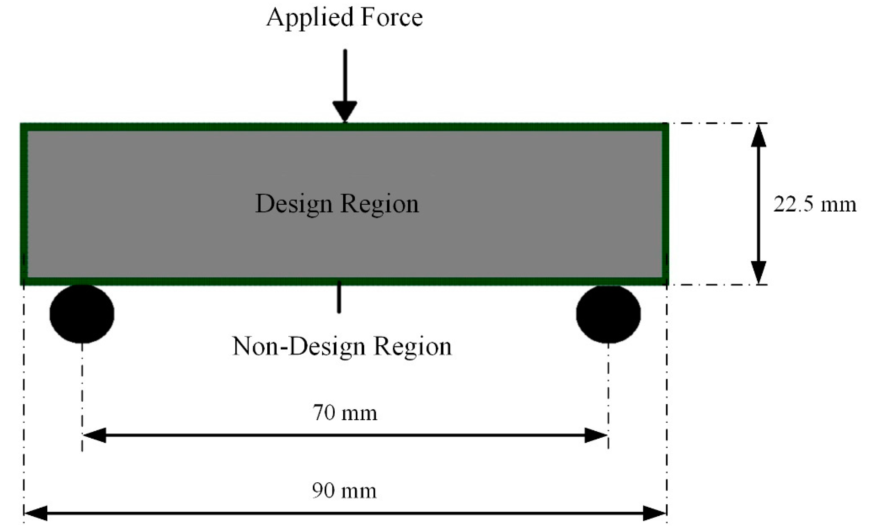
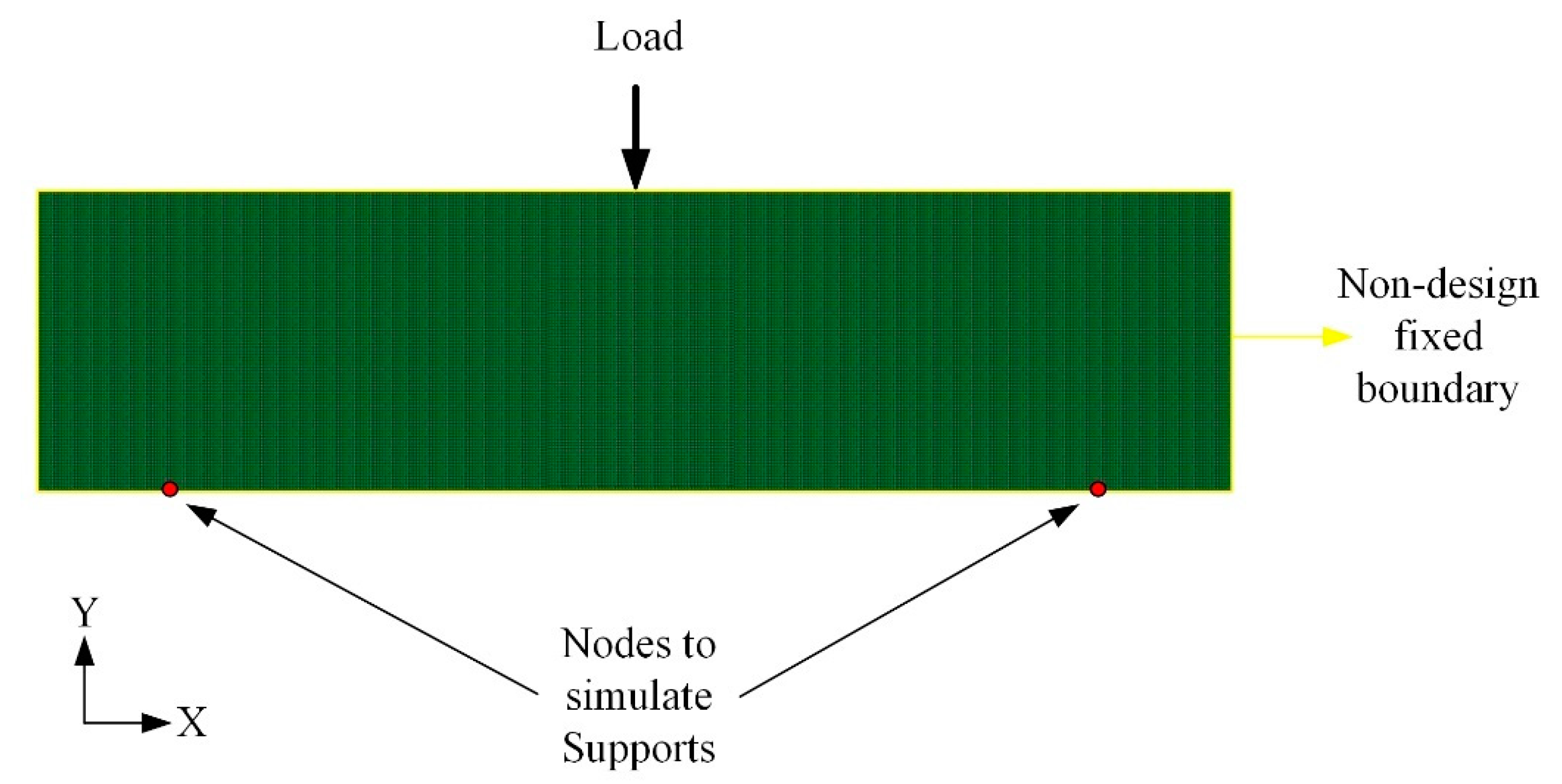
- In order to simplify the computational time, the beam was divided into plain strain quad elements.
- In order to improve the resolution of the design iterations, the computation of the beam was performed by considering the length and the width of the beam to be 180 mm × 50 mm (more than twice of the considered beam dimensions).
- The element size was 0.5 mm × 0.5 mm.
- An arbitrary load of 100 N was applied centrally, acting in the downward direction.
- Two nodes (140 mm) apart from each other were fixed to simulate the simply supported bending beam.
- The material property considered for the design optimisation was an isotropic material with a Young’s Modulus of 1 GPa and a Poisson’s ratio of 0.3.
- The optimisation was performed to maximise the stiffness of the beam while reducing the volume of the beam to 50%.
3.2. Topology-Optimised Lattice Units
3.3. LPBF Printing of the Beams
4. Results
5. Inverse Material Modelling for Solid Beam
5.1. Simulation of Solid Beam under Bending
5.2. Mesh Convergence for 3D Solid Beam under Three-Point Bending Test
5.3. Validation of 3D Finite Element Contact Modelling
5.4. Validation of Quarter Beam Model for Inverse Material Modelling
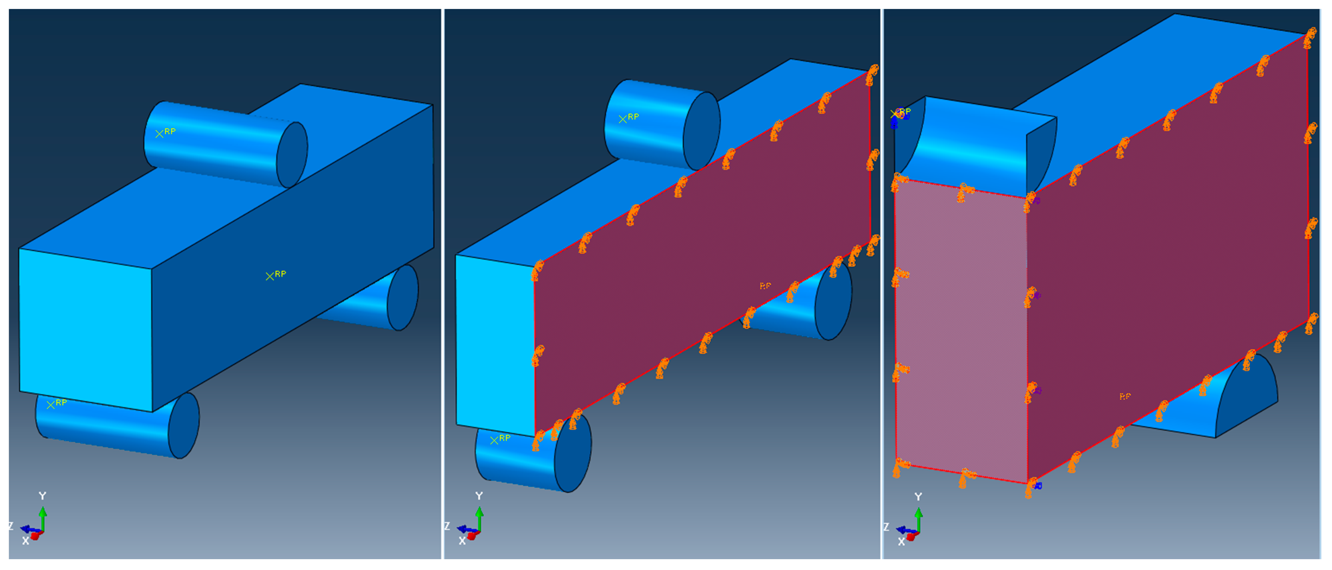
- For half and quarter model of the solid beam, the highlighted face of the beam parallel to the XY plane was constrained for translation in Z and rotation in X and Y directions.
- For the quarter of the solid beam, the highlighted face of the beam parallel to the XY plane was constrained for translation in X and rotation in Y and Z directions.
5.5. Solid-Beam Material Modelling
6. Simulation of BESO-Topology-Optimised Beams
- The quarter beam was selected for FE model setup.
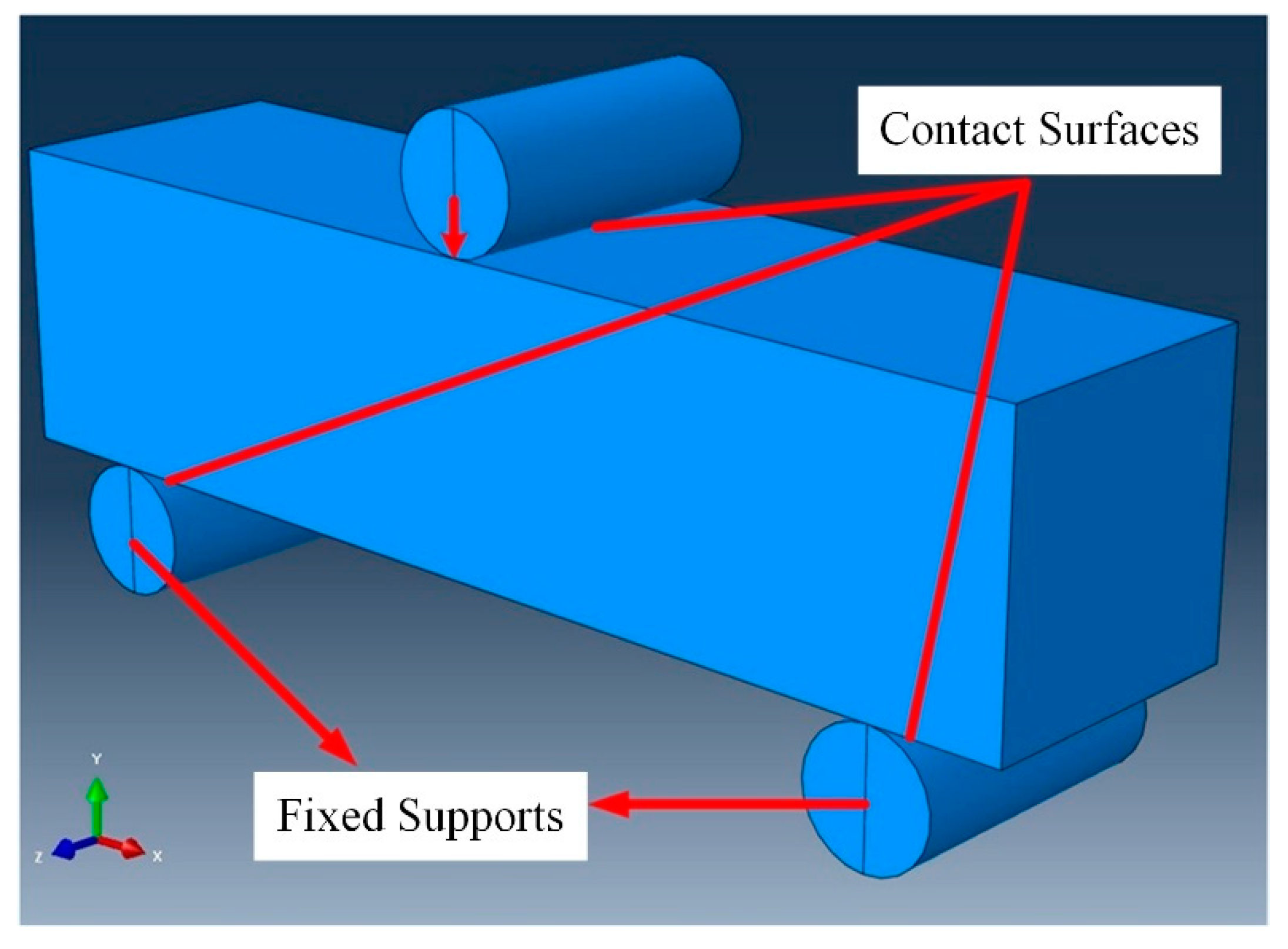
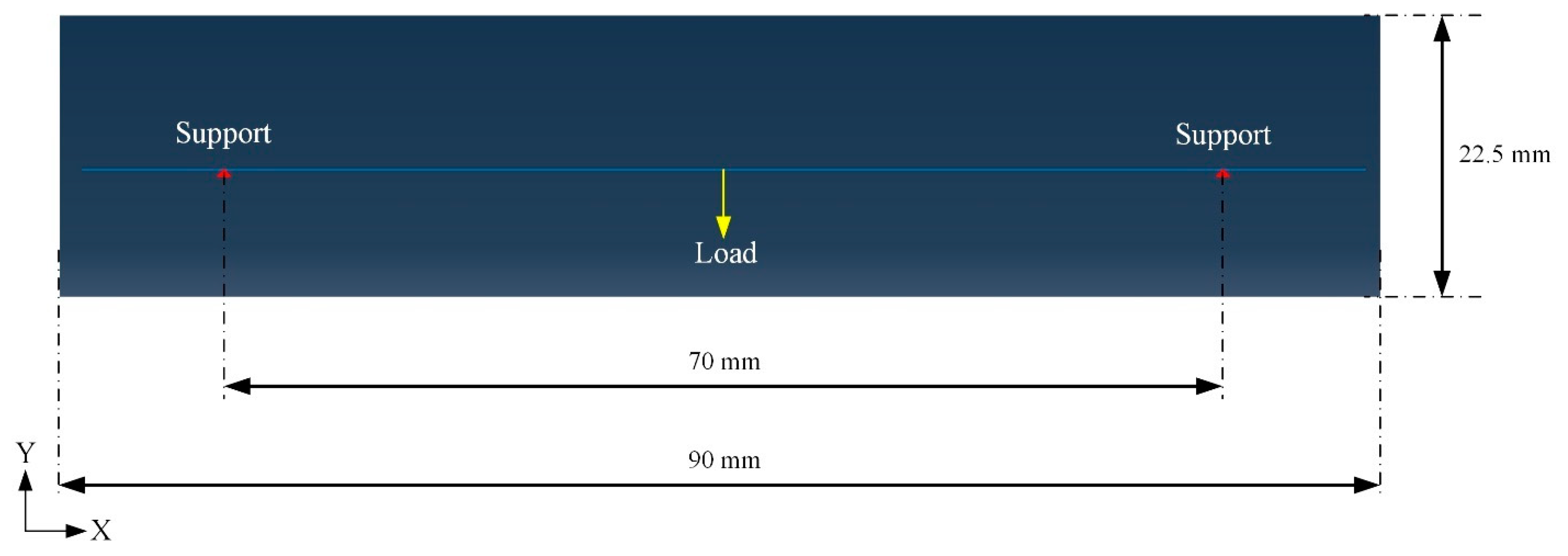
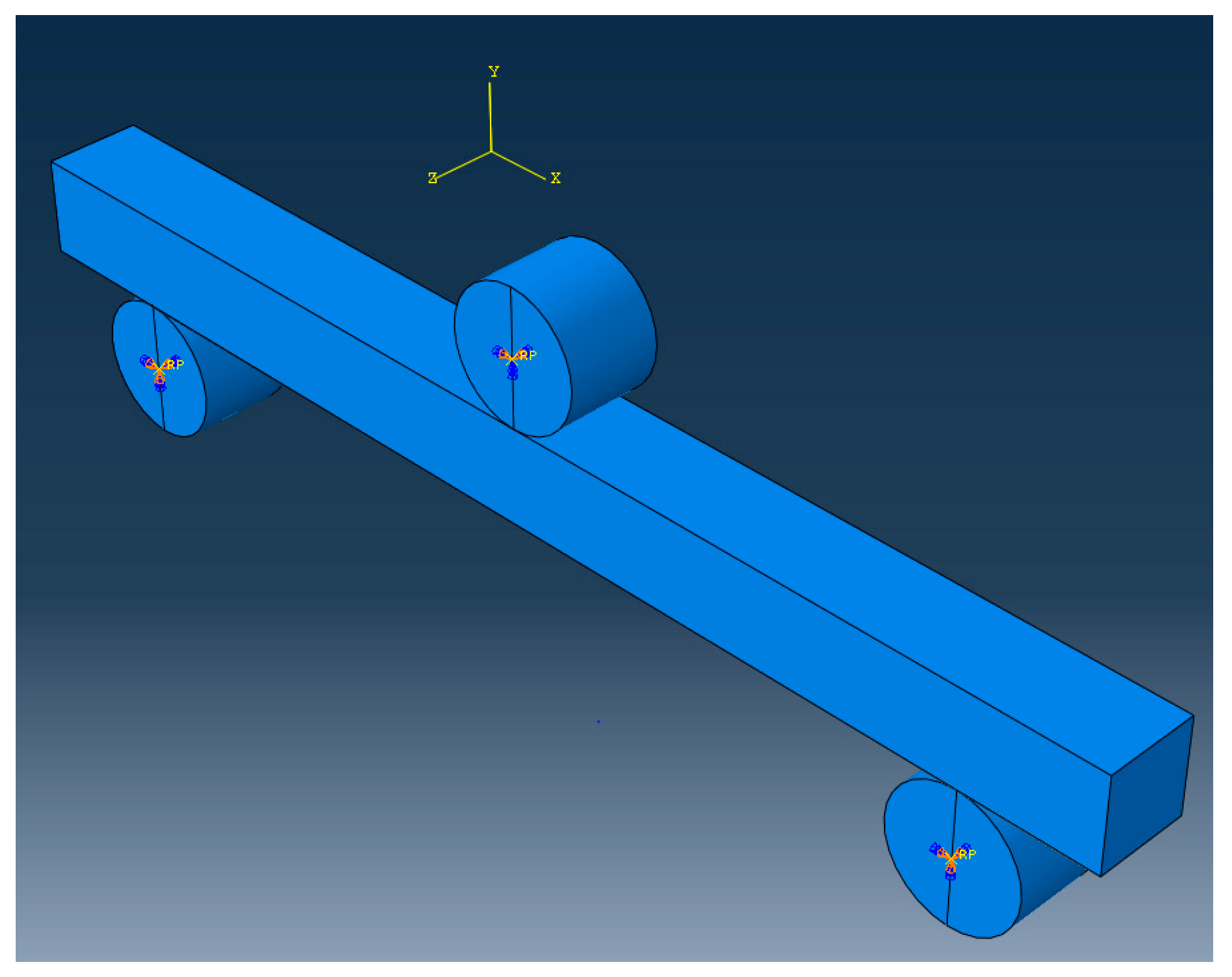
- The positions of the indenter and roller were as per the experimental setup (explained in Section 5.1).
- The indenter and roller were set up as discrete rigid parts, while the beam was set as a deformable part.
- Eight-node brick element was selected for the beams.
- The material model defined was as per the inverse material model of the LPBF-printed solid beam under the three-point bend test, as mentioned in Table 4.
- Contact interaction was set up as per the validated contact modelling described in Section 5.3.
- Displacement boundary conditions applied to indenter to mimic experimental setup.
- Planes of symmetries’ boundary conditions were applied as described in Section 5.4.
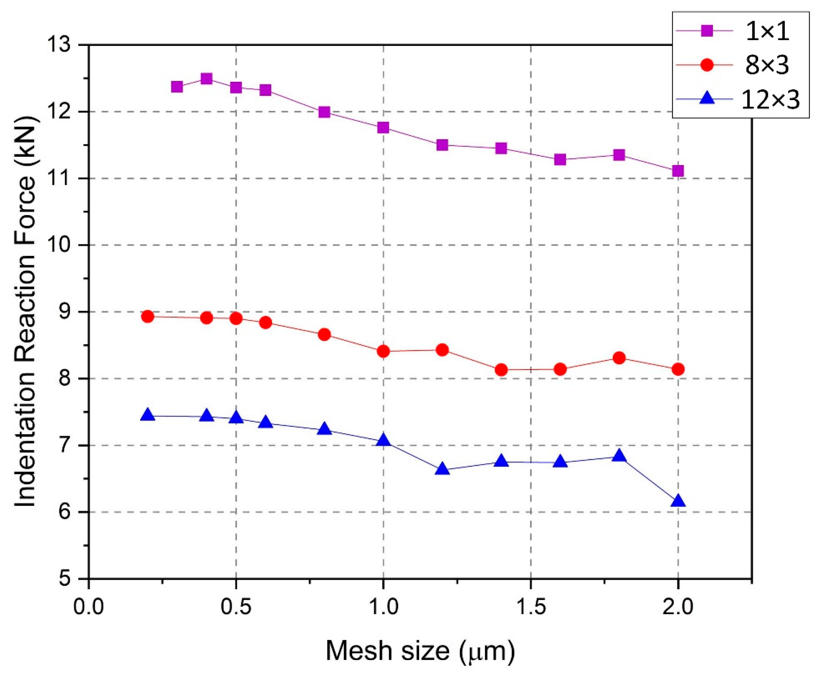
- Mesh-convergence study was carried out for the three BESO-optimised beams as described in Section 6.1.
- The reaction force and displacement of the reference point on the indenter were extracted to plot force vs. beam deflection from the FE output file, as described in Section 5.2.
6.1. Mesh Convergence for BESO-Optimised Beams
6.2. Comparison of Experimental Data with Simulation Results of BESO-Optimised Beams
7. Material Models for BESO Design Beams
8. Conclusions
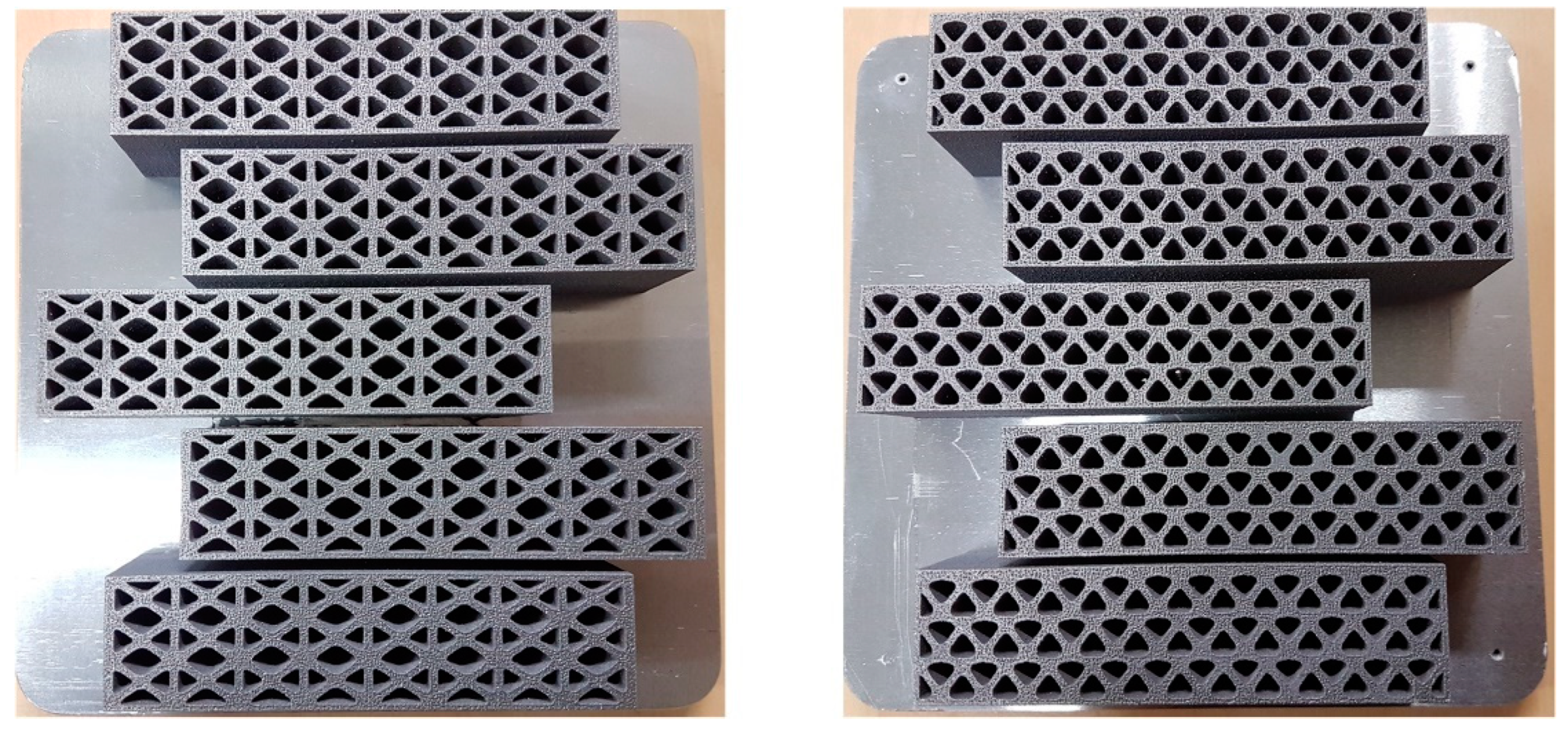
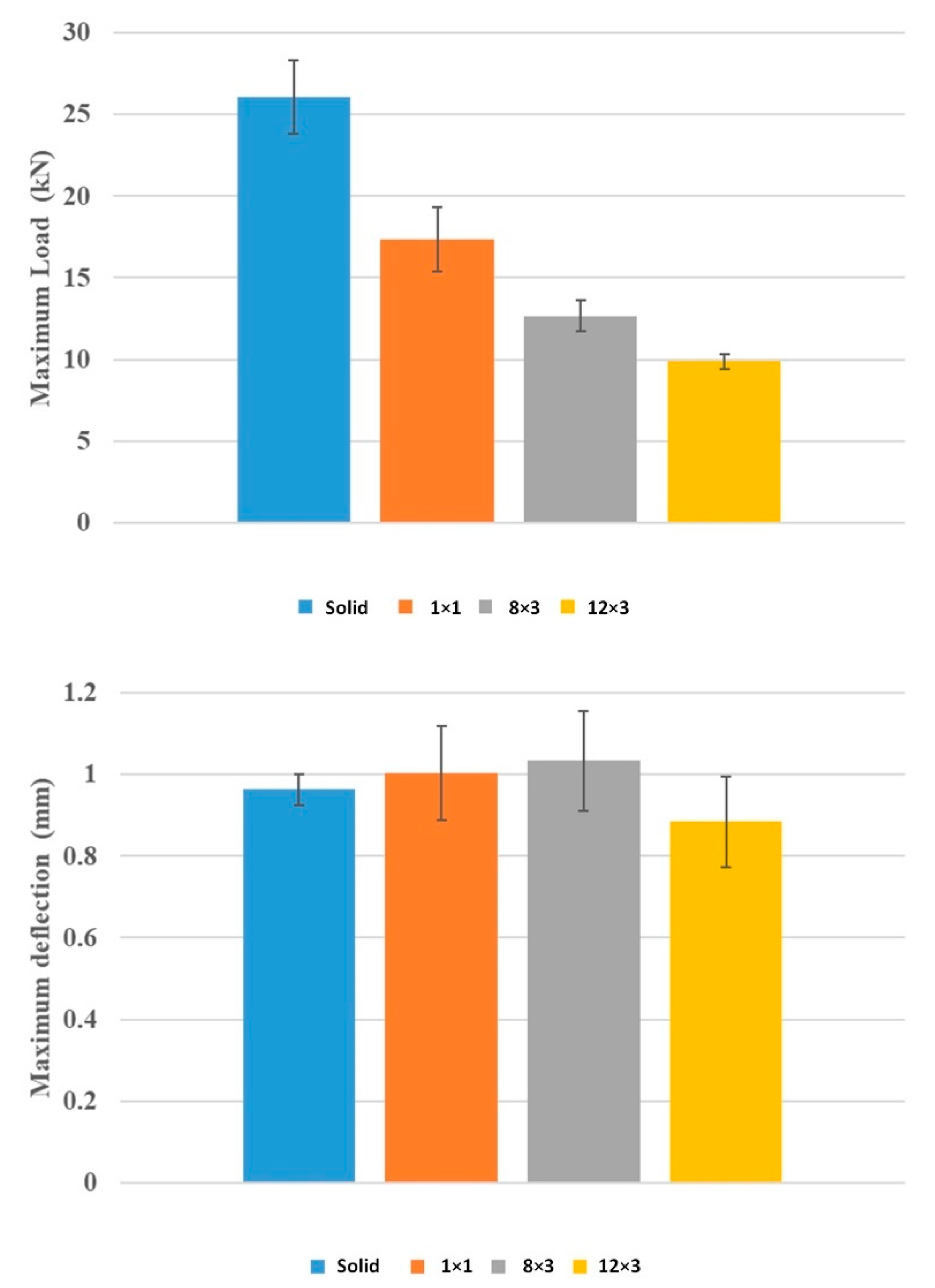
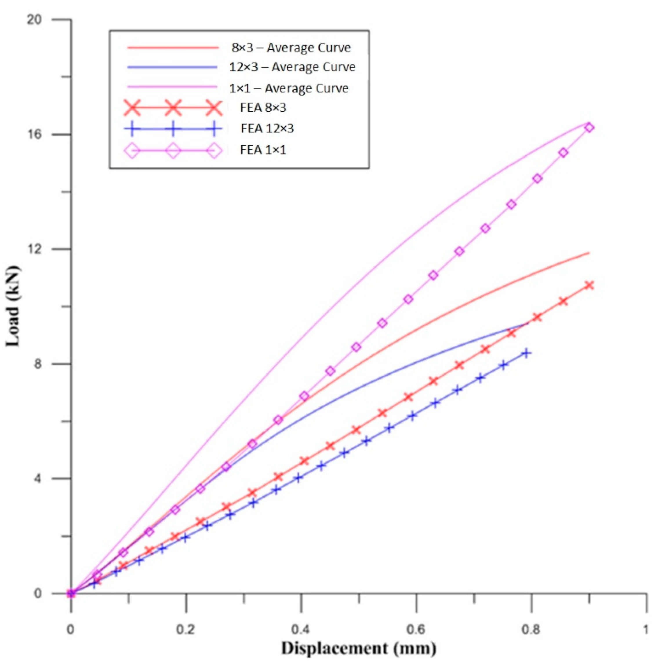
- The LPBF-printed beams were subjected to standard three-point bending, and a comparison of load–deflection curves of the three types of topology-optimised (TO) beams was made and compared with LPBF-printed solid beam. Out of the three TO lattice beams, the 1 × 1 lattice beam exhibited the best load-bearing capacity at 17 ± 2 kN, followed by the 8 × 3 lattice beam at 13 ± 1 kN and then the 12 × 3 lattice beam at 10 ± 1 kN.
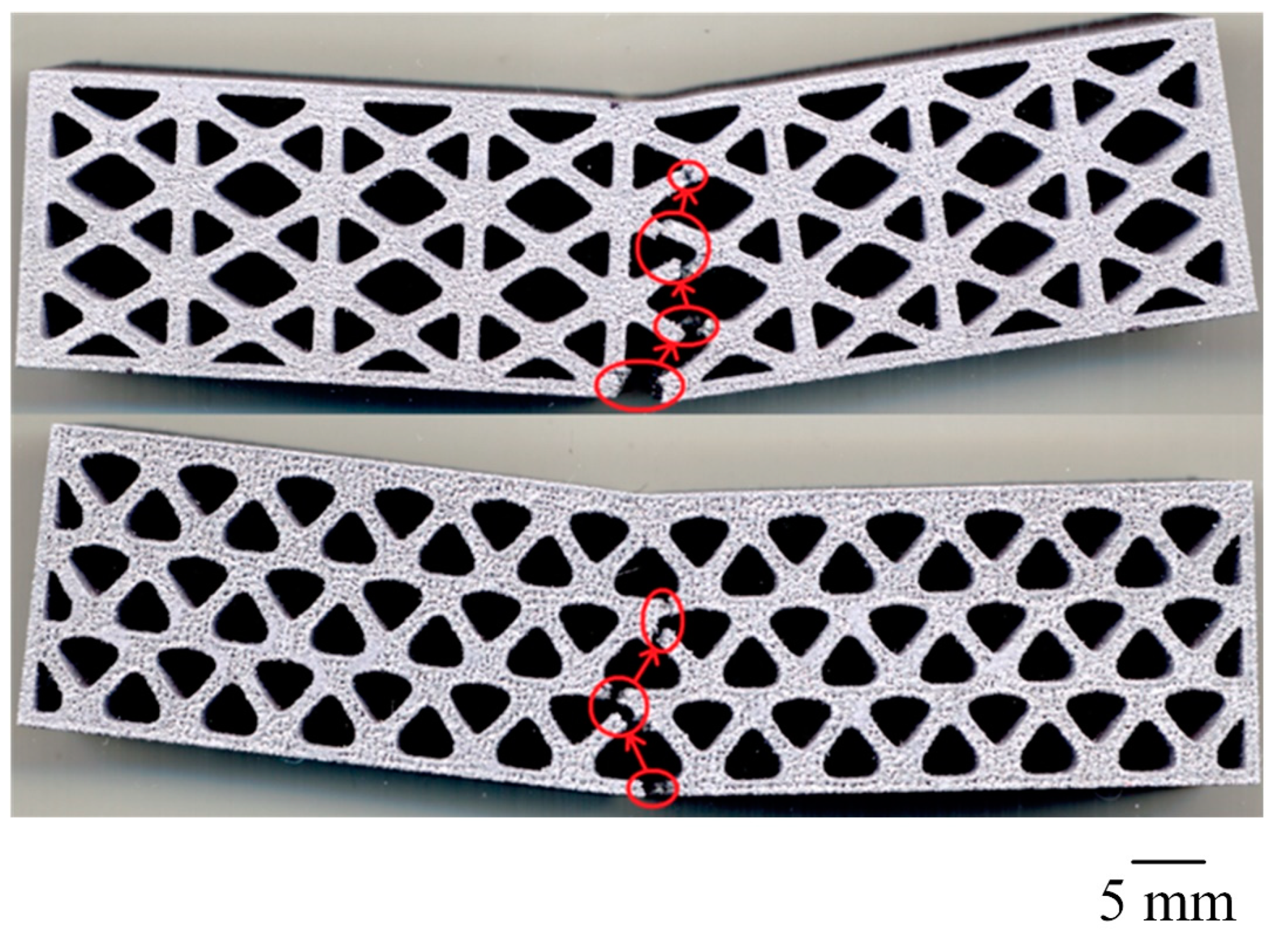
- The BESO-optimised beams had a lower load-bearing capacity with a similar beam deflection to the solid beam prior to failure, and they all failed in a brittle manner.
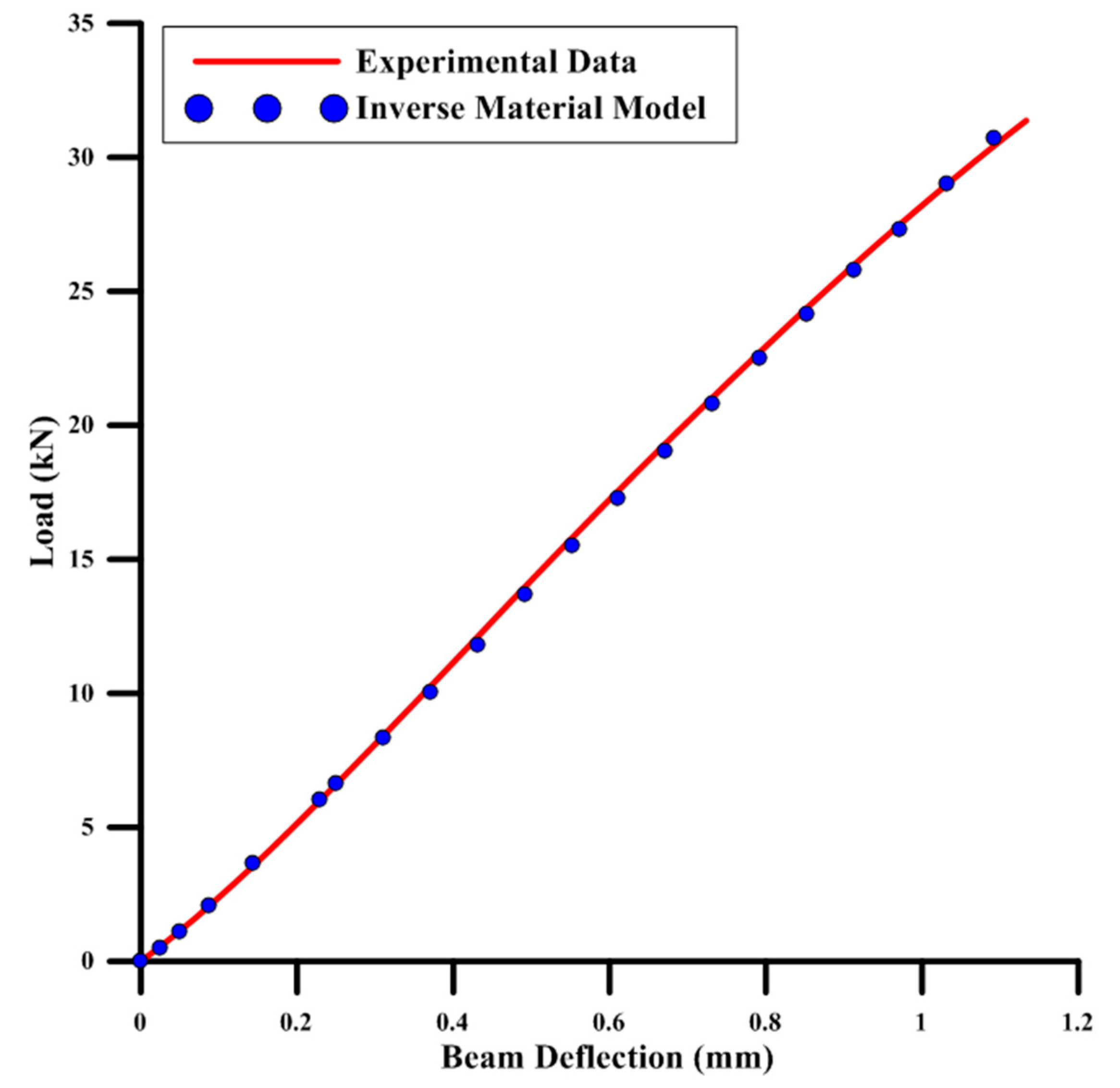
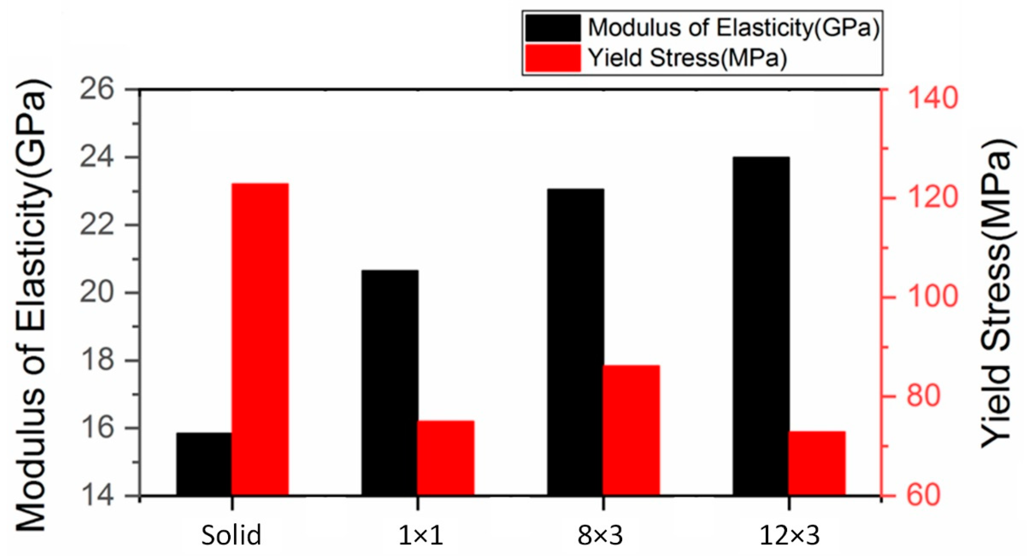
- The 3D FE model was compared against Timoshenko’s beam theory, as well as a 1D FE beam model, and the 3D FE model was found to be comparable with theoretical calculations. With the help of the Isight parameter-optimisation tool, along with the 3D FE model, the elastic–plastic material model of the solid LPBF-printed AlSi12 beam was developed. For this study, the material model of the solid LPBF-printed AlSi12 beam was used to predict the bending behaviour of the three BESO-optimised beams. It was found that the experimental bend curves of the three BESO beams were significantly different when compared to their respective FE simulation. It was hypothesised that the LPBF-printed AlSi12 material property depended on the design of the beams, as well as the other LPBF process parameters. This was further investigated by identifying the material models of the three BESO beams with the inverse material modelling technique (similar to the one used for identifying the material model for the solid LPBF-printed AlSi12 beam). It was found that the four material models of LPBF-printed AlSi12 beams (i.e., solid, 1 × 1, 8 × 3, and 12 × 3 beams) showed different yield stresses. The BESO-optimised beams tend to yield earlier when compared to the solid beam.
- Therefore, it is not possible to accurately simulate the mechanical performance of TO lattice-structured LPBF-printed parts under bending load by using the material properties of an anisotropic LPBF-printed solid component of the same material. Moreover, it can also be concluded that elastic regime properties of anisotropic LPBF-printed material cannot be used for lattice-structured parts since these parts exhibit plastic behaviour upon contact with bending loads.
- In the future, a new material model or simulation technique needs to be developed that can account for the changes in material behaviour after/during topology optimisation.
Author Contributions
Funding
Data Availability Statement
Acknowledgments
Conflicts of Interest
References
- Kladovasilakis, N.; Tsongas, K.; Karalekas, D.; Tzetzis, D. Architected Materials for Additive Manufacturing: A Comprehensive Review. Materials 2022, 15, 5919. [Google Scholar] [CrossRef] [PubMed]
- Rashid, R.; Masood, S.H.; Ruan, D.; Palanisamy, S.; Huang, X.; Rahman Rashid, R.A. Topology Optimisation of Additively Manufactured Lattice Beams for Three-Point Bending Test. In Proceedings of 2018 International Solid Freeform Fabrication Symposium, Austin, Austin, TX, USA, 13–15 August 2018. [Google Scholar]
- Sigmund, O.; Maute, K. Topology optimization approaches. Struct. Multidiscip. Optim. 2013, 48, 1031–1055. [Google Scholar] [CrossRef]
- Liu, J.; Zhu, N.; Chen, L.; Liu, X. Structural Multi-objective Topology Optimization in the Design and Additive Manufacturing of Spatial Structure Joints. Int. J. Steel Struct. 2022, 22, 649–668. [Google Scholar] [CrossRef]
- Aremu, A.; Ashcroft, I.; Hague, R.; Wildman, R.; Tuck, C. Suitability of SIMP and BESO Topology Optimization Algorithms for Additive Manufacture. In Proceedings of 21st Annual International Solid Freeform Fabrication Symposium, Austin, TX, USA, 9–11 August 2010; pp. 679–692. [Google Scholar]
- Sigmund, O. A 99 line topology optimization code written in Matlab. Struct. Multidiscip. Optim. 2001, 21, 120–127. [Google Scholar] [CrossRef]
- Ntintakis, I.; Stavroulakis, G.E. Infill Microstructures for Additive Manufacturing. Appl. Sci. 2022, 12, 7386. [Google Scholar] [CrossRef]
- Dassault Systems Simulia. TOSCA Optimization Technology. Available online: https://www.3ds.com/products-services/simulia/products/tosca/ (accessed on 10 October 2022).
- VR&D. GENESIS Structural Optimization Extension for ANSYS® Mechanical. Available online: http://www.vrand.com/products/gsam-gtam/ (accessed on 10 October 2022).
- Altair. Altair® Inspire™. Available online: https://www.altair.com/inspire (accessed on 10 October 2022).
- Huang, X.; Xie, M. Evolutionary Topology Optimization of Continuum Structures: Methods and Applications; Wiley: Hoboken, NJ, USA, 2010. [Google Scholar]
- Spear, D.G.; Lane, J.S.; Palazotto, A.N.; Kemnitz, R.A. Computational based investigation of lattice cell optimization under uniaxial compression load. Results Mater. 2022, 13, 100242. [Google Scholar] [CrossRef]
- ISO/ASTM International 52900; Additive Manufacturing—General Principles—Fundamentals and Vocabulary. ISO: Geneva, Switzerland, 2021.
- Ponnusamy, P.; Rahman Rashid, R.A.; Masood, S.H.; Ruan, D.; Palanisamy, S. Mechanical Properties of SLM-Printed Aluminium Alloys: A Review. Materials 2020, 13, 4301. [Google Scholar] [CrossRef]
- Xiao, Z.; Yang, Y.; Xiao, R.; Bai, Y.; Song, C.; Wang, D. Evaluation of topology-optimized lattice structures manufactured via selective laser melting. Mater. Des. 2018, 143, 27–37. [Google Scholar] [CrossRef]
- Wang, X.; Qin, R.; Chen, B. Mechanical properties and energy absorption capability of a topology-optimized lattice structure manufactured via selective laser melting under axial and offset loading. Proc. Inst. Mech. Eng. Part C J. Mech. Eng. Sci. 2022, 236, 10221–10236. [Google Scholar] [CrossRef]
- Zhang, B.; Pei, X.; Zhou, C.; Fan, Y.; Jiang, Q.; Ronca, A.; D’Amora, U.; Chen, Y.; Li, H.; Sun, Y.; et al. The biomimetic design and 3D printing of customized mechanical properties porous Ti6Al4V scaffold for load-bearing bone reconstruction. Mater. Des. 2018, 152, 30–39. [Google Scholar] [CrossRef]
- García-Moreno, F. Commercial Applications of Metal Foams: Their Properties and Production. Materials 2016, 9, 85. [Google Scholar] [CrossRef] [PubMed]
- nTopology. nTopology. Available online: https://ntopology.com/ (accessed on 10 October 2022).
- Autodesk. Netfabb. Available online: https://www.autodesk.com.au/products/netfabb/ (accessed on 10 October 2022).
- Rezaie, R.; Badrossamay, M.; Ghaie, A.; Moosavi, H. Topology Optimization for Fused Deposition Modeling Process. Procedia CIRP 2013, 6, 521–526. [Google Scholar] [CrossRef]
- Castilho, M.; Dias, M.; Gbureck, U.; Groll, J.; Fernandes, P.; Pires, I.; Gouveia, B.; Rodrigues, J.; Vorndran, E. Fabrication of computationally designed scaffolds by low temperature 3D printing. Biofabrication 2013, 5, 035012. [Google Scholar] [CrossRef] [PubMed]
- Gardan, N. Knowledge Management for Topological Optimization Integration in Additive Manufacturing. Int. J. Manuf. Eng. 2014, 2014. [Google Scholar] [CrossRef]
- Brandt, M.; Sun, S.J.; Leary, M.; Feih, S.; Elambasseril, J.; Liu, Q.C. High-Value SLM Aerospace Components: From Design to Manufacture. Adv. Mater. Res. 2013, 633, 135–147. [Google Scholar] [CrossRef]
- Ponnusamy, P.; Masood, S.H.; Ruan, D.; Palanisamy, S.; Rashid, R.A.R.; Mukhlis, R.; Edwards, N.J. Dynamic compressive behaviour of selective laser melted AlSi12 alloy: Effect of elevated temperature and heat treatment. Addit. Manuf. 2020, 36, 101614. [Google Scholar] [CrossRef]
- Rashid, R.; Masood, S.H.; Ruan, D.; Palanisamy, S.; Rahman Rashid, R.A.; Elambasseril, J.; Brandt, M. Effect of energy per layer on the anisotropy of selective laser melted AlSi12 aluminium alloy. Addit. Manuf. 2018, 22, 426–439. [Google Scholar] [CrossRef]
- Huang, X.; Xie, Y.M. Optimal design of periodic structures using evolutionary topology optimization. Struct. Multidiscip. Optim. 2008, 36, 597–606. [Google Scholar] [CrossRef]
- ASTM International E290-14; Standard Test Methods for Bend Testing of Material for Ductility. West Conshohocken: Montgomery County, PA, USA, 2014.
- Rahman Rashid, R.A.; Mallavarapu, J.; Palanisamy, S.; Masood, S.H. A comparative study of flexural properties of additively manufactured aluminium lattice structures. Mater. Today Proc. 2017, 4, 8597–8604. [Google Scholar] [CrossRef]
- Da, D.; Xia, L.; Li, G.; Huang, X. Evolutionary topology optimization of continuum structures with smooth boundary representation. Struct. Multidiscip. Optim. 2018, 57, 2143–2159. [Google Scholar] [CrossRef]
- Siddique, S.; Imran, M.; Walther, F. Very high cycle fatigue and fatigue crack propagation behavior of selective laser melted AlSi12 alloy. Int. J. Fatigue 2017, 94, 246–254. [Google Scholar] [CrossRef]
- Lanoue, F.; Vadean, A.; Sanschagrin, B. Finite element analysis and contact modelling considerations of interference fits for fretting fatigue strength calculations. Simul. Model. Pract. Theory 2009, 17, 1587–1602. [Google Scholar] [CrossRef]
- Underwood, J.H.; Kapp, J.A.; Witherell, M.D. Fracture Testing with Arc Bend Specimens. In US Army Armament Research and Development Center Large Caliber Weapon Systems Laboratory; US Army ARDC: Watervliet, NY, USA, 1985. [Google Scholar]
- Roark, R.J. Formulas for Stress and Strain; R. R. Donnelley & Son: Chicago, IL, USA, 1965; pp. 286–323. [Google Scholar]
- Strek, T.; Michalski, J.; Jopek, H. Computational Analysis of the Mechanical Impedance of the Sandwich Beam with Auxetic Metal Foam Core. Phys. Status Solidi (B) 2019, 256, 1800423. [Google Scholar] [CrossRef]
- Roy, S.; Gebert, J.-M.; Stasiuk, G.; Piat, R.; Weidenmann, K.A.; Wanner, A. Complete determination of elastic moduli of interpenetrating metal/ceramic composites using ultrasonic techniques and micromechanical modelling. Mater. Sci. Eng. A 2011, 528, 8226–8235. [Google Scholar] [CrossRef]
- Alomarah, A.; Zhang, J.; Ruan, D.; Masood, S.; Lu, G. Mechanical Properties of the 2D Re-entrant Honeycomb Made via Direct Metal Printing. IOP Conf. Ser. Mater. Sci. Eng. 2017, 229, 012038. [Google Scholar] [CrossRef]
- Ono, K. Strain-Hardening equations and uniform strain. Metall. Mater. Trans. B 1972, 3, 749–751. [Google Scholar] [CrossRef]
- Calleja-Ochoa, A.; Gonzalez-Barrio, H.; López de Lacalle, N.; Martínez, S.; Albizuri, J.; Lamikiz, A. A New Approach in the Design of Microstructured Ultralight Components to Achieve Maximum Functional Performance. Materials 2021, 14, 1588. [Google Scholar] [CrossRef]










| Material | Laser Power (W) | Scan Speed (mm/s) | Layer Thickness (μm) | Hatch Distance (μm) | Defocus Distance (mm) | Scan Strategy | Chamber Gas |
|---|---|---|---|---|---|---|---|
| AlSi12 | 285 | 2500 | 40 | 100 | −4 | Scan ‘H’ * | Argon |
| Beam Type | Maximum Bending Load (kN) | Deflection at Maximum Bending Load (mm) | Deflection at Complete Failure (mm) |
|---|---|---|---|
| Solid | 26.08 ± 2.27 | 0.96 ± 0.04 | 0.96 ± 0.04 |
| 1 × 1 | 17.38 ± 1.98 | 1.00 ± 0.12 | 1.00 ± 0.12 |
| 8 × 3 | 12.67 ± 0.95 | 1.03 ± 0.12 | 1.22 ± 0.09 |
| 12 × 3 | 9.87 ± 0.46 | 0.86 ± 0.11 | 1.13 ± 0.17 |
| Mesh Size (mm) | Number of 8 Node Brick Elements | Indenter Reaction Force (kN) | Change in Indenter Reaction Force (%) |
|---|---|---|---|
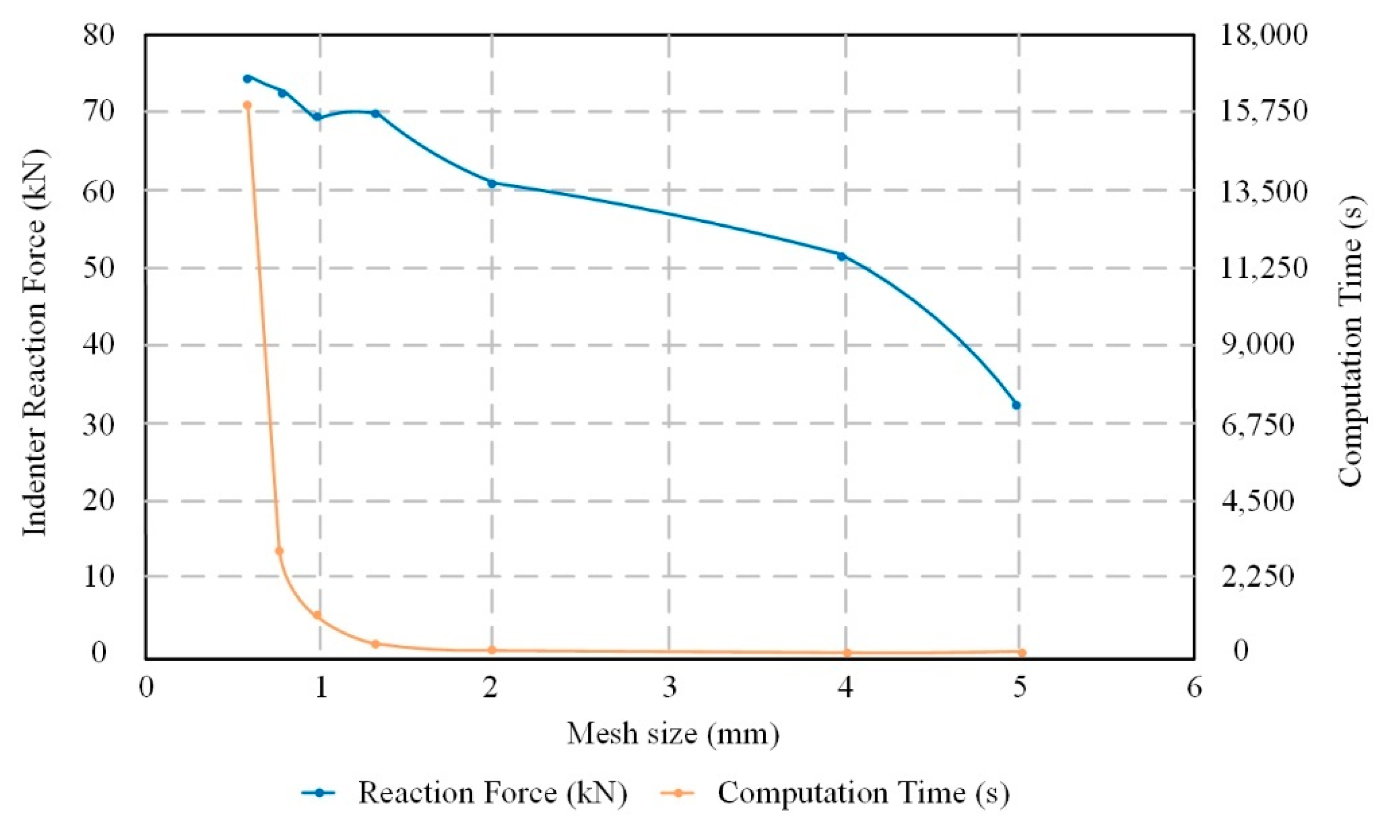
| 5 | 450 | 32.41 | - |
| 4 | 864 | 51.37 | 58.50 |
| 2 | 5445 | 60.94 | 18.63 |
| 1.33 | 19,941 | 69.81 | 14.55 |
| 1 | 47,610 | 69.26 | −0.79 |
| 0.8 | 89,376 | 72.44 | 4.59 |
| 0.6 | 218,044 | 74.27 | 2.53 |
| Material Parameter | Inverse Material Model Value |
|---|---|
| Modulus of Elasticity (E) | 15.85 GPa |
| Yield Strength (σ0) | 122.88 MPa |
| Ludwig’s Strength Coefficient (K) | 718.77 MPa |
| Ludwig’s Strain Hardening Index (n) | 0.43 |
| Mesh Size (μm) | Number of 8-Node Brick Elements | Indentation Reaction Force (kN) | Change in Indenter Reaction Force (%) |
|---|---|---|---|
| 2 | 5178 | 11.11 | - |
| 1.8 | 5598 | 11.35 | 2.16 |
| 1.6 | 6958 | 11.28 | −0.62 |
| 1.4 | 8152 | 11.45 | 1.51 |
| 1.2 | 11,088 | 11.5 | 0.44 |
| 1 | 15,378 | 11.76 | 2.26 |
| 0.8 | 26,054 | 11.99 | 1.96 |
| 0.6 | 44,555 | 12.32 | 2.75 |
| 0.5 | 84,732 | 12.36 | 0.32 |
| 0.4 | 131,012 | 12.49 | 1.05 |
| 0.3 | 338,352 | 12.37 | −0.96 |
| Mesh Size (μm) | Number of 8-Node Brick Elements | Indentation Reaction Force (kN) | Change in Indenter Reaction Force (%) |
|---|---|---|---|
| 2 | 10,422 | 8.14 | - |
| 1.8 | 10,290 | 8.31 | 2.09 |
| 1.6 | 12,243 | 8.14 | −2.05 |
| 1.4 | 15,448 | 8.13 | −0.12 |
| 1.2 | 19,611 | 8.43 | 3.69 |
| 1 | 26,191 | 8.41 | −0.24 |
| 0.8 | 36,848 | 8.66 | 2.97 |
| 0.6 | 69,331 | 8.84 | 2.08 |
| 0.5 | 100,648 | 8.9 | 0.68 |
| 0.4 | 152,292 | 8.91 | 0.11 |
| 0.2 | 990,024 | 8.93 | 0.22 |
| Mesh Size (μm) | Number of 8-Node Brick Elements | Indentation Reaction Force (kN) | Change in Indenter Reaction Force (%) |
|---|---|---|---|
| 2 | 7422 | 6.15 | - |
| 1.8 | 7920 | 6.83 | 11.06 |
| 1.6 | 9716 | 6.74 | −1.32 |
| 1.4 | 12,320 | 6.75 | 0.15 |
| 1.2 | 14,787 | 6.63 | −1.78 |
| 1 | 18,568 | 7.06 | 6.49 |
| 0.8 | 27,944 | 7.23 | 2.41 |
| 0.6 | 49,989 | 7.33 | 1.38 |
| 0.5 | 79,327 | 7.4 | 0.95 |
| 0.4 | 137,844 | 7.43 | 0.41 |
| 0.2 | 959,000 | 7.44 | 0.13 |
| Material Parameter | Inverse-Material-Model Values | |||
|---|---|---|---|---|
| Solid Beam | 1 × 1 Beam | 8 × 3 Beam | 12 × 3 Beam | |
| Modulus of Elasticity (E, GPa) | 15.14 | 20.74 | 23.06 | 24.01 |
| Yield Stress (σ0, MPa) | 218.68 | 75.06 | 86.23 | 72.91 |
| Ludwig’s Strength Coefficient (K, MPa) | 718.77 | 718.77 | 718.77 | 718.77 |
| Ludwig’s Strain Hardening Index (n) | 0.43 | 0.43 | 0.43 | 0.43 |
Disclaimer/Publisher’s Note: The statements, opinions and data contained in all publications are solely those of the individual author(s) and contributor(s) and not of MDPI and/or the editor(s). MDPI and/or the editor(s) disclaim responsibility for any injury to people or property resulting from any ideas, methods, instructions or products referred to in the content. |
© 2023 by the authors. Licensee MDPI, Basel, Switzerland. This article is an open access article distributed under the terms and conditions of the Creative Commons Attribution (CC BY) license (https://creativecommons.org/licenses/by/4.0/).
Share and Cite
Rashid, R.; Masood, S.; Ruan, D.; Palanisamy, S.; Huang, X.; Rahman Rashid, R.A. Design Optimization and Finite Element Model Validation of LPBF-Printed Lattice-Structured Beams. Metals 2023, 13, 184. https://doi.org/10.3390/met13020184
Rashid R, Masood S, Ruan D, Palanisamy S, Huang X, Rahman Rashid RA. Design Optimization and Finite Element Model Validation of LPBF-Printed Lattice-Structured Beams. Metals. 2023; 13(2):184. https://doi.org/10.3390/met13020184
Chicago/Turabian StyleRashid, Riyan, Syed Masood, Dong Ruan, Suresh Palanisamy, Xiaodong Huang, and Rizwan Abdul Rahman Rashid. 2023. "Design Optimization and Finite Element Model Validation of LPBF-Printed Lattice-Structured Beams" Metals 13, no. 2: 184. https://doi.org/10.3390/met13020184
APA StyleRashid, R., Masood, S., Ruan, D., Palanisamy, S., Huang, X., & Rahman Rashid, R. A. (2023). Design Optimization and Finite Element Model Validation of LPBF-Printed Lattice-Structured Beams. Metals, 13(2), 184. https://doi.org/10.3390/met13020184


