Article

Effects of Furnace Length on the Thermal Performance of a Walking Beam Reheating Furnace

The State Key Laboratory of Refractories and Metallurgy, Wuhan University of Science and Technology, Wuhan 430081, China
*
Author to whom correspondence should be addressed.
Metals 2023, 13(12), 1946; https://doi.org/10.3390/met13121946
Submission received: 16 October 2023 / Revised: 3 November 2023 / Accepted: 22 November 2023 / Published: 28 November 2023

Abstract

:
The influence of furnace length on several key performance indicators of a reheating furnace such as the fuel consumption, thermal efficiency and through-thickness temperature uniformity of a discharged slab was investigated. Energy balance equations of radiation set up by the zone method were solved by coupling them with the heat conduction equations of the slab. The zone model was validated by actual data collected during an instrumented slab trial. The simulation results showed that the model predictions were in good agreement with actual measurements. Under the premise that the throughput rate and the total fuel consumption were fixed, every additional meter of the preheating zone length increased the slab discharge temperature by about 10.75 °C and decreased the exhaust temperature by about 13.29 °C, but made no change in the section temperature difference in the slab at discharge; every additional meter of the soaking zone length decreased the section temperature difference in the slab at discharge by about 2.88 °C, but made a somewhat gentle change in the slab discharge temperature and exhaust temperature. For the existing furnace, the actual length was not suitable to be changed, so the relative length was defined as representing the actual length, which could be indirectly changed by adjusting the current fuel consumption. After optimization, the relative lengths of the preheating zone and soaking zone increased by five meters and one meter, respectively, while the relative lengths of the first and second heating zones decreased by five meters and one meter, respectively, and the section temperature difference in the slab at discharge, exhaust temperature and fuel consumption simultaneously decreased.

1. Introduction

With the proposals of “carbon peaking and carbon neutrality”, reducing fuel consumption has become an urgent task for industrial technological innovation. In China, the industrial furnace bears the brunt of reduction in fuel consumption owing to its only 30% thermal efficiency but almost 1/4 of the total energy consumption of the country [1,2,3]. As an important equipment prior to hot rolling, the main function of a reheating furnace is to raise the temperature of a slab to the softening point as high as 1200–1350 °C. In order to improve the thermal efficiency of a furnace, reduce its fuel consumption and improve the heating quality of a slab, the temperature and temperature uniformity of the slab and the temperature of the exhaust gas must be effectively controlled [4].
Because slab temperatures cannot be measured directly in most control systems, the heating quality of a slab is often too difficult to control. In the past decades, mathematical models have been developed to predict the temperature field within a furnace and a slab. In general, the convection heat transfer between gas and slab is much smaller than the radiative heat transfer in a reheating furnace with high temperatures of 1200–1350 °C, and thus the former is often omitted in simplified simulations. As a consequence, establishing a radiative heat transfer model has become the key step to understanding the temperature field within a reheating furnace.
KIM JG et al. [5,6] conducted steady-state calculations on the turbulent and radiative heat transfer in a heating furnace and analyzed the factors affecting the heat transfer of steel billets; HARRISH J et al. [7,8] studied the temperature distribution of steel billets in different areas of a heating furnace; CUI M et al. [9] established a modified mathematical model to study the factors affecting the total heat transfer coefficient over the length of a heating furnace; JANG J Y et al. [10,11,12] used optimization algorithms to obtain the optimal heating method for steel billets, reducing energy consumption and improving the temperature uniformity of the billets; TANG G W et al. [13,14] compared the steel billet results obtained from three-dimensional and two-dimensional simulations of a heating furnace and verified the feasibility of the two methods; Wang Zisong et al. [15,16,17] established a fully coupled three-dimensional model of a walking beam heating furnace and analyzed the factors affecting the temperature distribution of steel billets; WANG J Y et al. [18,19] established a heat transfer model for an I-beam walking beam heating furnace and studied the heating process of the I-beam in the furnace; and LI PJ et al. [20] studied the effects of rotational conditions, tooth slot temperature and steel pipe size on the temperature uniformity of steel pipes by establishing conduction and radiative heat transfer models between steel pipes, tooth slots, furnace gas and furnace walls. However, the influence of structural parameters is seldom reported in the literature, especially the effect of a water-cooled beam on the heat balance of a furnace. In fact, structural parameters not only relate directly to the thermal efficiency and energy consumption [21], but also affect the heating quality of a slab.
Hence, the present work aims to clarify the influence of furnace length on the thermal performance of a reheating furnace. The mathematical model of a walking beam reheating furnace considering a water-cooled beam was established to predicate the exhaust gas temperature and temperature uniformity of the slab at discharge and various other positions along the furnace length. The zone method [22,23] was adopted to analyze convection and radiation interchanges between the hot furnace gases and the refractory and slab surface within the model. The influences of the lengths of the preheating section and the soaking zone on the temperatures of the slab and flue gas based on the simulation results were discussed.

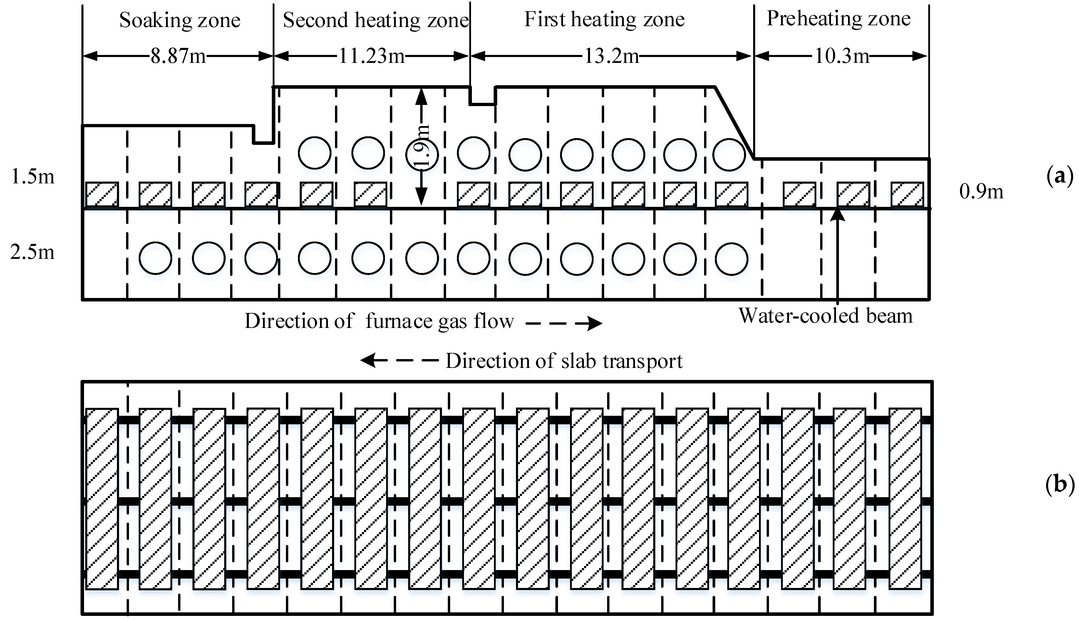
2. Furnace Details and Zoning Arrangement

Figure 1 illustrates the walking beam reheating furnace used with dimensions of 43.59 m in length, 11.7 m in width and 3.4~4.0 m in height. There were nine horizontal water-cooled beams 2.5 m away from the furnace bottom, but only three are shown in Figure 1 for clarity. The overall furnace chamber was divided into upper and lower chambers by beams. The furnace was equipped with a total of 21 burners, in which a mixed coke oven and blast furnace gas with a low calorific value of 8778 kJ/m3 were used as fuel. In accordance with the zone method, the furnace was evenly split into 44 sections in length, 2 sections of upper and lower chambers in height and 1 section across its width. Note that the numbers of zone divisions were essentially determined by the relative positions of the burner arrangement within the furnace, and in this case, no burner fired into more than one zone.
In order to verify the validity of the zone model, an instrumented trial was beforehand conducted to investigate the actual slab heating profile and furnace gas temperature in the reheating furnace. In this trial, the temperature profiles along the slab thickness relied on the limited K-type armored thermocouples uniformly embedded along the slab width direction. During the trial period, the furnace was operating at a throughput rate of 300 t/h, and the total fuel input of each zone (from left to right in Figure 1) was 4681, 16,632, 14,112 and 0 m3/h, respectively. Meanwhile, the proportion of volume space for the upper and lower furnace chambers at the heating zone accounted for 45% and 55%, respectively. Each slab with dimensions of 9600 × 1200 × 230 mm was heated to a target drop-out temperature between 1220 and 1250 °C within 150 min.

3. Zone Model and Solution

The zone method for radiation analysis splits a furnace chamber into finite numbers of isothermal volume and surface zones. For these zones, energy balances were formulated, which could be solved to yield the transient temperature and heat flux at each zone. A system of the zone method for radiation analysis includes the volume zones N g , surface zones N s of the slab and surface zones N w of the furnace wall, and the following energy balance equations are proposed in the present study.
For the i-th volume (gas) zone:
σ j = 1 , j i N g G j G i ¯ ( T g j 4 T g i 4 ) + σ j = 1 N w W j G i ¯ ( T w j 4 T g i 4 ) + σ j = 1 N s S j G i ¯ ( T s j 4 T g i 4 ) + Q c o m , i + Q f , i + Q a , i + Q m o v , i Q c , i = 0
Likewise, for the i-th surface (furnace wall) zone:
σ j = 1 N g G j S i ¯ ( T g j 4 T s i 4 ) + σ j = 1 N w W j S i ¯ ( T w j 4 T s i 4 ) + σ j = 1 N s S j S i ¯ ( T s j 4 T s i 4 ) + Q c 1 , i = Q s , i
For the i-th surface (slab) zone:
σ j = 1 N g G j W i ¯ ( T g j 4 T w i 4 ) + σ j = 1 , j i N w W j W i ¯ ( T w j 4 T w i 4 ) + σ j = 1 N s S j W i ¯ ( T s j 4 T w i 4 ) + h g w i F w i ( T g j T w i ) = T w i T 1 h + d w i λ i F w i
The radiation terms in these energy balance equations are written in terms of exchange factors, known as total flux areas, which are denoted by G j G i ¯ , W j G i ¯ ( G j W i ¯ ), S j G i ¯ ( G j S i ¯ ), W j W i ¯ , W j S i ¯ ( S j W i ¯ ) and S j S i ¯ for gas–gas, wall–gas, surface–gas, wall–wall, wall–surface and surface–surface, respectively. These total exchange areas allow for the effects of surface emissivity and the non-gray behavior of the radiant interchange within the furnace chamber.
The time-dependent internal node temperatures of the slab were solved by using the transient heat conduction model. In the slab’s interior zone, the temperature gradient along the movement direction of the slab was much smaller than that along the thickness direction, so the temperature distribution along the slab width was considered to be uniform. Although previous 3D simulations reported in the literature for similar problems have shown that the temperature at the corners of slabs decreases, these corners would ultimately be removed in actual production, so the significance of 3D simulation on the transient conduction of the slab is not as large as imagined [24]. For the above reasons, the one-dimensional heat conduction equation for the slab’s interior zone is written as the following:
ρ c T τ = y ( λ T y )
The furnace gas in the upper and lower furnace chambers was assumed to be independent, so the energy balance equations of the furnace gas in the two parts may have been different because the heat sink item in the lower furnace gas involved the radiation and convection exchange between the hot furnace gas and water-cooled beam, which equaled the heat conduction of the water-cooled beam along the radial direction in the steady state. Therefore, the energy balance of heat conduction along the thickness direction and the total energy taken away by cooling can be written as the following:
Q g l i = Q o u t i i n i = Q z i
The outer surface and inner surface temperatures of a water-cooled beam are usually unknown, so in this case, they were considered to be equal to the temperatures of the inner and outer surfaces of the furnace wall, respectively. The heat loss of each water-cooled beam can be described as the following:
2 π l ( T w o u t T w i n ) ln ( d 1 d 2 ) λ 1 + ln ( d 2 d 3 ) λ 2 + ln ( d 3 d 4 ) λ 3 = Q z L
In order to improve the model’s accuracy, the physical property parameters of the slab and gas emissivity due to varying temperatures were supposed to be modified. The slab chosen in this work was Q235 carbon steel, and its thermal conductivity [25] and specific heat capacity can be described as the following:
λ t = λ 0 + K 1 t 100 K 2 c h t t 0 / 100
c t = c 0 + a 1 t / 1000 n + a 2 a 3 t t 0
When a heating furnace burns gas fuel, the effect of the furnace’s temperature on its gas emissivity is greater and can be modified according to the following equations [26,27].
ε g = 1 e K q r n P s
K q = 0.78 + 1.6 r H 2 O s P n / P 0 0.1 1 0.00037 T g × 10 5
s = 3.6 V A
where εg is the emissivity of the furnace gas; γH2O is the volume fraction of water in the furnace gas; γn is the shared triatomic gas in the furnace gas (H2O and CO2); P0 is the atmospheric pressure; P is the total pressure of the gas; Pn is the partial pressure of the triatomic gas; s is the average ray stroke length; V is the gas volume; and A is the wall area.
In this paper, the three-dimensional steady-state simulation of thermal radiative exchange among the hot furnace gases and the refractory and slab surfaces was coupled with the transient simulation of heat conduction of the slab via cyclic iterations of the slab’s surface temperature. The energy balance equations of radiation were solved by the principal variable correction method, in which the direct exchange area was calculated using the number theory grid method [28]. The heat conduction equation of the slab was solved by the full implicit finite difference [29,30].
The specific algorithm is as follows. At first, an initial value of the slab surface temperature was given. Hence, the corresponding temperatures of the furnace gas and furnace wall were obtained by the energy balance equations of thermal radiative exchange. Then, the heat fluxes of the upper and lower surfaces of the slab were obtained, which were used as the boundary conditions of the heat conduction equation at the slab’s interior zone. Thus, the temperature field including all nodes of the slab was attained. Thirdly, the values of the slab surface temperatures calculated by the energy balance equations were compared to those obtained from the heat conduction equation. If the two values were not equal, the temperature value of the slab surface obtained by the heat conduction equation was used in the energy balance equations, and this cyclic iteration continued until the two values were equal. Finally, the temperature field of the slab and furnace was established.
In this paper, the heat exchange in the furnace was analyzed by the segment method, and the energy balance equations of the furnace gas section, the furnace enclosure section and the surface section of the billet were coupled with the internal heat conductivity equation of the billet to solve iteratively. The principal variable correction method was used to solve the energy balance equation, and the thermal conductivity equation of the billet was implicitly finitely differential. Using MATLAB R2018b software to write a program code, this method has the advantages of being faster, more convenient and easier to modify compared with traditional research simulations.

4. Results and Analysis

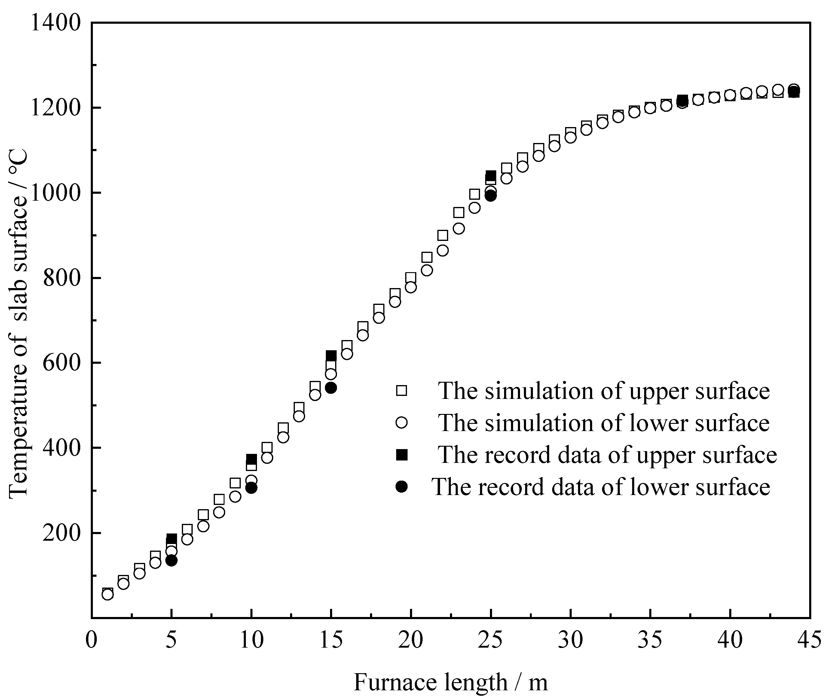
4.1. Validity of the Zone Model

Two sets of temperature data were supplied to verify the validity of the zone model. The first set of data is the predictions from the zone model during which the furnace was operating at 300/h (see Figure 2). In the preheating zone, the section temperature difference in the slab was small and the mean temperature of the furnace gas was not high. This was due to the lack of heat input from the burners and the effect of heat absorption of the cold slab. In the heating zone, the mean temperature of the furnace gas increased with the heat input from fuel, and the section temperature difference in the slab increased. In the soaking zone, the variation in gas temperature along the furnace length and the section temperature difference in the slab were much smaller than those in the heating zone with the decrease in fuel consumption. The second set of data is the temperature values of the upper and lower surfaces of the slab from an instrumented slab trial, as shown in Figure 3. The data were used to verify the simulation results of the zone model, and the simulation results show that there was only 5.9% maximum error. Based on this comparison, the predictions from the zone model proved to perfectly agree with actual measurements, suggesting that the zone model is feasible.

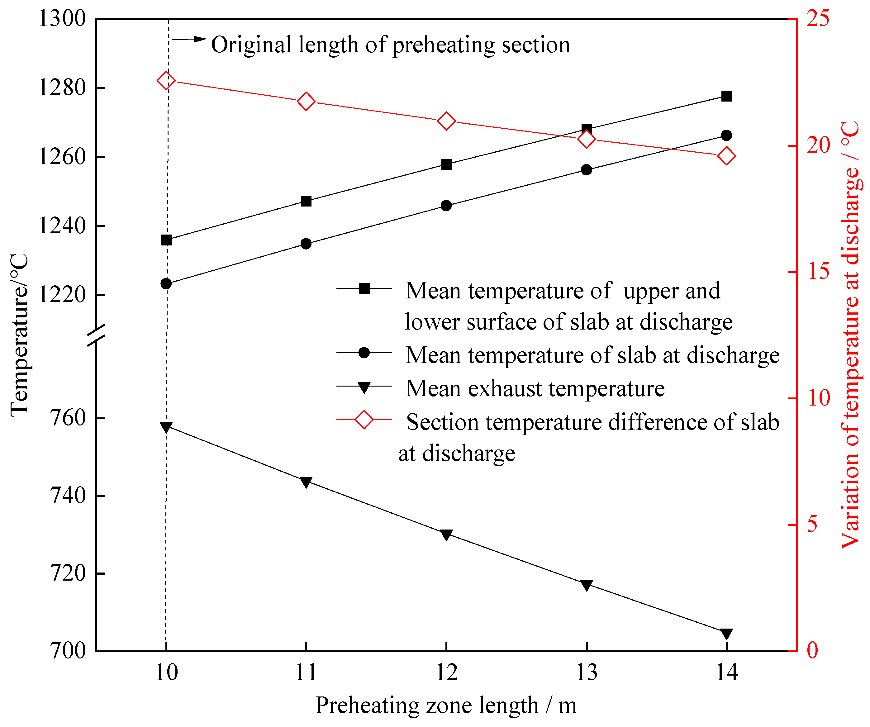
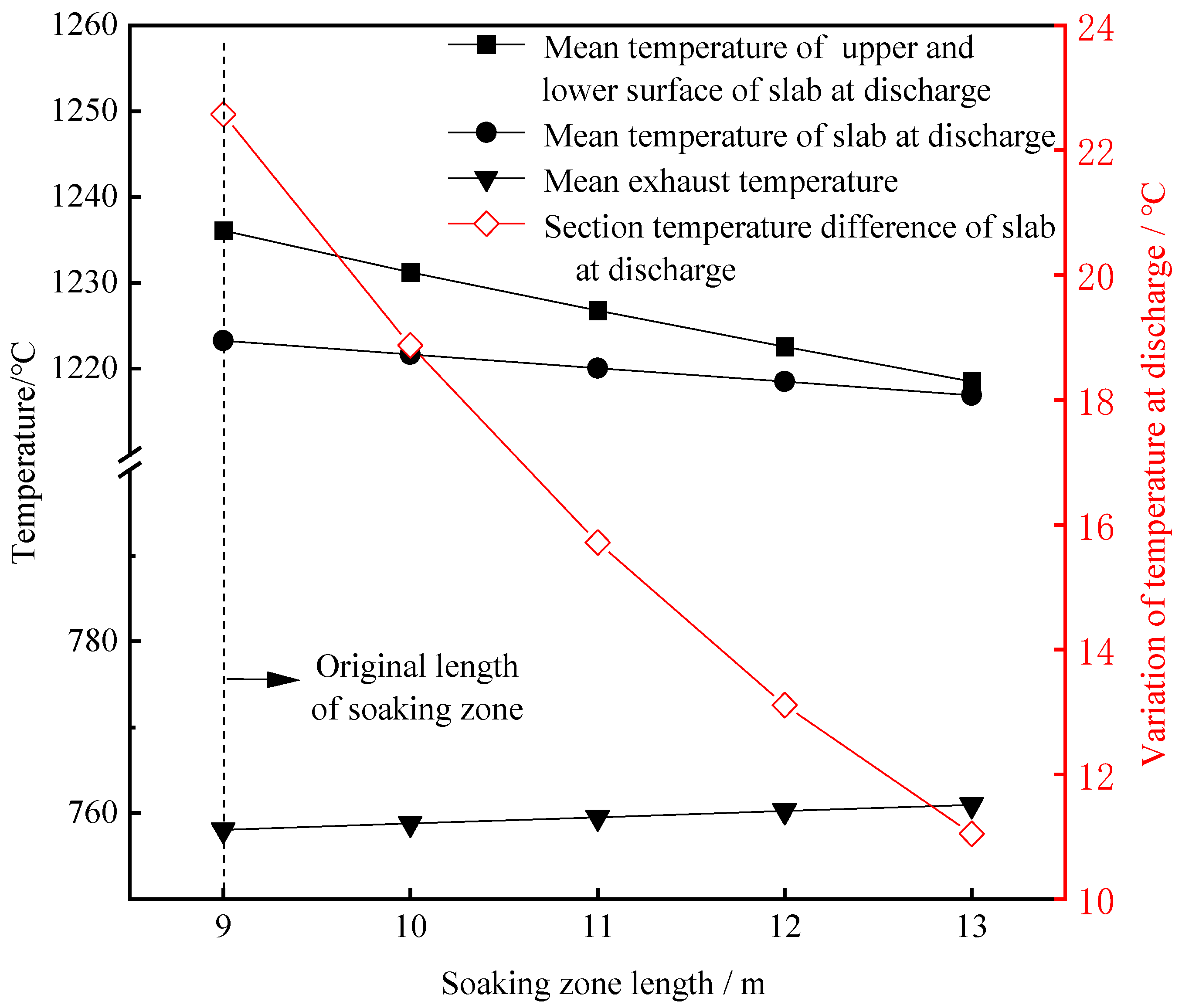
4.2. Influence of the Lengths of the Preheating Zone and Soaking Zone

The influences of the lengths of the preheating zone and soaking zone on the slab heating quality and the exhaust temperature at a throughput rate of 300 t/h are shown in Figure 4 and Figure 5, respectively. It can be seen from Figure 4 that when the length of the preheating zone increased by one meter, the slab discharge temperature increased by about 10.75 °C and the exhaust temperature decreased by about 13.29 °C, and the change in the section temperature difference in the slab at discharge can be almost ignored. This indicates that prolonging the length of the preheating zone can reduce heat loss, owing to hot exhaust gas, and hence improve the utilization efficiency of fuel, but cannot effectively reduce the section temperature difference in the slab. Figure 5 shows that the changes in the slab temperature and exhaust temperature were very small with the increase in the soaking zone length, while the section temperature difference in the slab decreased obviously. More specifically, when the length of the soaking zone increased by one meter, the section temperature difference in the slab was reduced by about 2.88 °C.
In summary, in order to reduce the exhaust temperature while minimizing the section temperature difference in the slab for the existing furnace, the preheating zone, soaking zone and heating zone should be lengthened appropriately, and the heating zone should shorten accordingly. The details will be discussed in the following subsection.

4.3. Influence of the Relative Lengths of the Preheating Zone and First Heating Zone

For actual industrial production lines, due to a comprehensive consideration of cost and other related factors, it was suitable to directly increase or shorten the length of the existing reheating furnace. In this case, the “relative length” is defined as the actual length of the furnace zones, which could be changed by adjusting the burning state of the burners. For example, under the premise of guaranteeing a throughput rate and total fuel consumption, when the total length of the preheating zone and first heating zone was fixed, the burners in part of the first heating zone near the preheating zone were turned off or turned down, and then part of the heating zone was transformed into the preheating zone. In this way, the relative length of the preheating zone increased and the relative length of the first heating zone decreased. After this adjustment, the slab temperature and exhaust temperature predicted by the zone model are shown in Figure 6.
When the relative length of the preheating zone increased by one meter on the basis of an original length of 10.3 m, the mean temperature of the slab at discharge increased by about 1.04 °C, the change in the section temperature difference in the slab at discharge was not obvious and the average flue gas temperature decreased by about 1.21 °C. When the relative length of the preheating zone increased, the length of the heating zone relatively decreased. Because of the fixed fuel consumption, the fuel distribution was more concentrated and the heat exchange time of the hot gas with the slab increased compared with that before adjustment, leading to the increasing slab temperature and decreasing exhaust temperature.
When the throughput rate was constant and the total lengths of the preheating zone and first heating zone were fixed, the length of the preheating zone increased and the length of the first heating zone shortened, the relative lengths of the preheating zone and the first heating zone were adjusted to observe the fuel consumption and exhaust temperature, and the specific setting is shown in Table 1. The fuel consumption and exhaust temperature decreased as the relative length of the preheating zone increased. In summary, increasing the length of the preheating zone and simultaneously shortening the length of the first heating zone are beneficial to improving the thermal efficiency of a furnace and saving fuel consumption.

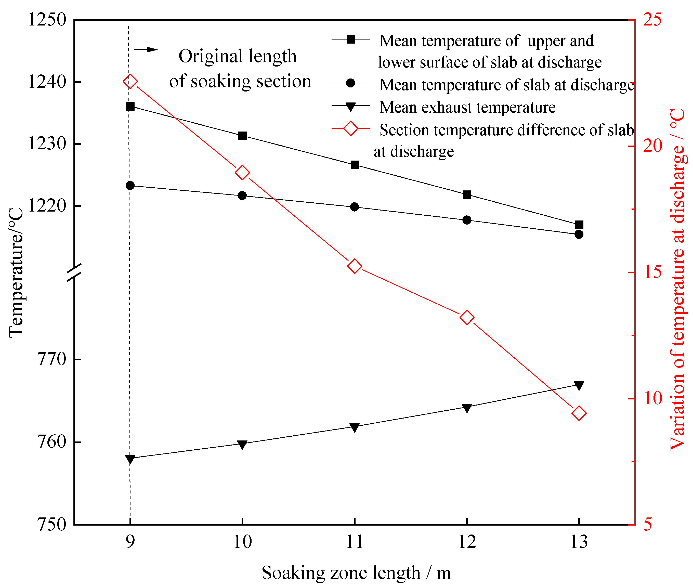
4.4. Influence of the Relative Lengths of the Second Heating Zone and Soaking Section

Likewise, when the throughput rate and total fuel consumption were fixed, the total length of the soaking zone and the second heating zone was fixed, the length of the soaking zone increased and the length of the second heating zone shortened. The zone model predictions of the slab temperature and exhaust temperature after adjusting the relative lengths of the soaking zone and second heating zone are shown in Figure 7.
From Figure 7, when the total length of the soaking zone and second heating zone were fixed, as the relative length of the soaking section increased by one meter, the mean slab temperature decreased by 1.97 °C and the section temperature difference in the slab decreased by 3.29 °C, while the exhaust temperature increased by 2.23 °C. In the reheating furnace, the soaking zone maintained the mean temperature of the slab and reduced the section temperature difference. It did not have the effect of heating it up, however, which is the role of the heating zone. Therefore, after the increase in the soaking section and the shortening of the heating section, although the temperature difference in the slab section was reduced, the furnace length was shortened in disguise, resulting in the motion of the heat source toward the exhaust port. Afterward, the heat exchange duration between the hot furnace gas and slab in the furnace shortened, so it is not surprising that the slab discharge temperature decreased while the exhaust temperature increased. In summary, increasing the relative length of the soaking zone and simultaneously shortening the relative length of the second heating zone favor the reduction in the section temperature difference in a slab, but are harmful to the reduction in exhaust temperature.

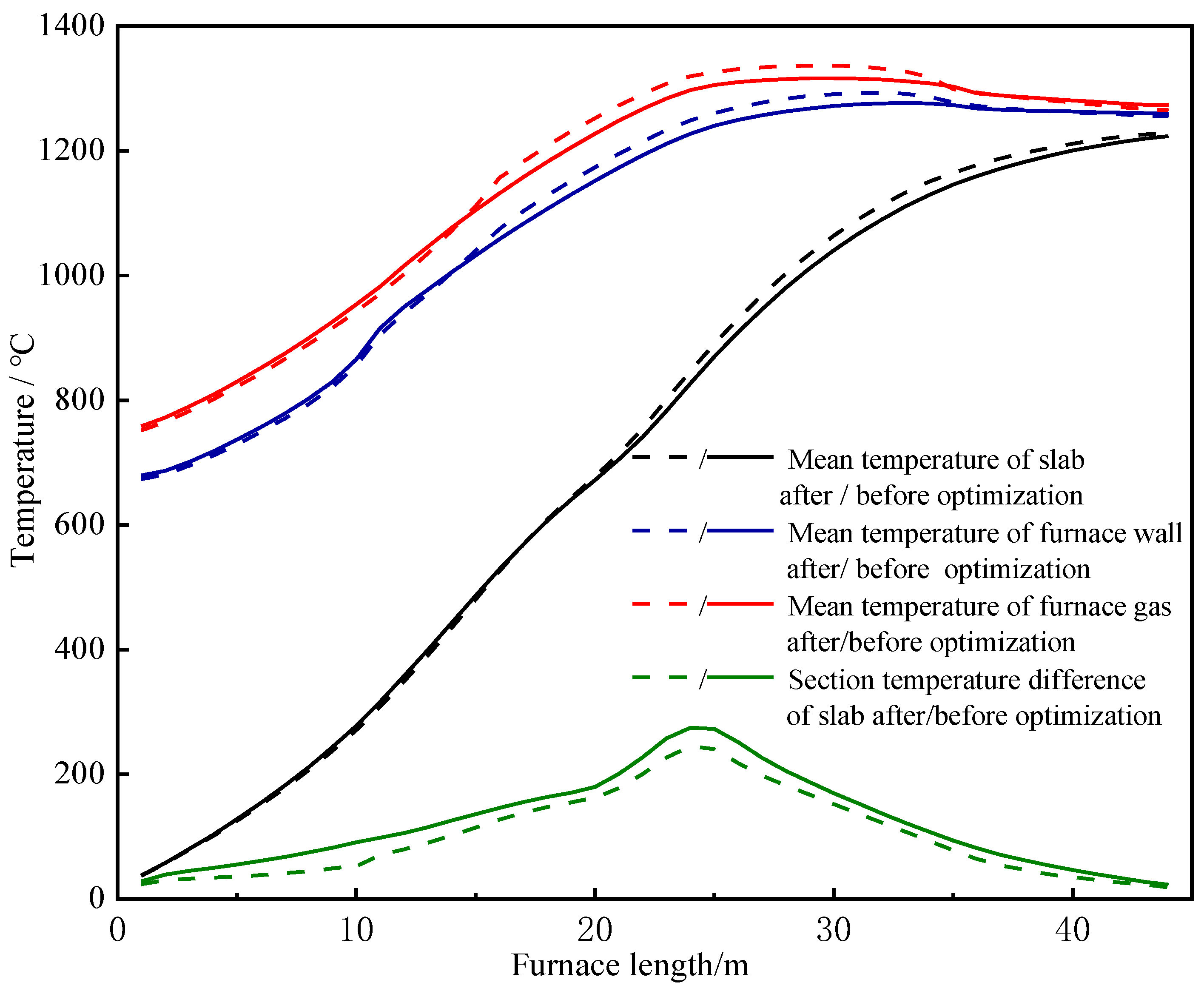
4.5. Optimization of the Lengths of Each Zone in the Reheating Furnace

As mentioned above, increasing the length of the preheating section reduced the exhaust temperature, while increasing the length of the soaking zone reduced the section temperature difference in the slab. Therefore, a reasonable arrangement of the preheating zone length and soaking zone length in a reheating furnace can significantly both improve the thermal performance of the furnace and the heating quality of the slab. For this aim, the following optimization was implemented.
When the throughput rate and total fuel consumption were fixed, optimization was fulfilled by increasing five meters of the relative length of the preheating zone and one meter of the relative length of the soaking zone; the preheating zone length was therefore increased by 2.5 m, first heating zone was shortened by 2.5 m, the immersion zone length was increased by 0.5 m and the second heating zone was shortened by 0.5 m. The simulative temperature profiles of each section before and after optimization are shown in Figure 8.
From Figure 8, it can be seen that the temperatures of the furnace gas and furnace wall surface increased in the heating zone and soaking zone but slightly decreased in the preheating section and first heating zone after optimization. The mean temperature of the slab decreased slightly in the preheating zone, but increased in the heating zone and soaking zone. The section temperature difference in the slab decreased in all zones. A detailed comparison of the data before and after optimization is shown in Table 2. It can be seen that after optimization, the mean flue gas temperature decreased by 6.71 °C, the mean temperature of the slab at discharge increased by 57 °C and the section temperature difference in the slab decreased by 3.93 °C.
On the basis of the above optimization, in order to further reduce fuel consumption under the premise of guaranteeing the throughput rate, the following optimization was performed: the relative length of the preheating zone was increased by five meters and the relative length of the soaking zone was increased by one meter, while the relative lengths of the first heating zone and second heating zone were decreased by five meters and one meter, respectively. The simulation results of this optimization are shown in Table 3.
In summary, after this optimization, the mean slab temperature remained unchanged, while the section temperature difference in the slab at discharge decreased by 3.7 °C, the exhaust temperature decreased by 10.64 °C and fuel consumption decreased by 0.7%. Compared with the former optimization, it can be seen that the reheating furnace was more energy-efficient and the heating quality of the slab was higher after optimization.

5. Conclusions

Based on the energy balance equations of the furnace gas section, the furnace circumference and the slab surface, the zone model was used to describe the radiative heat transfer in the furnace. The main variable correction method was utilized to solve the problem. The main conclusions of this paper are the following:
(1)
Increasing the relative length of the preheating section reduced the exhaust temperature but could not effectively reduce the section temperature difference in the slab. Increasing the relative length of the soaking zone reduced the section temperature difference in the slab but could not effectively change the slab temperature and exhaust temperature.
(2)
Increasing the length of the preheating zone and shortening the length of the first heating zone were favorable to save fuel consumption.
(3)
Increasing the relative length of the soaking section was favorable for the reduction in the section temperature difference in the slab, but harmful to the reduction in exhaust temperature.
(4)
When the length of the preheating zone increased by five meters, the length of the soaking zone increased by one meter, the length of first heating zone decreased by five meters and the length of the second heating zone decreased by one meter. The reheating furnace was more energy-efficient and the heating quality of the slab was higher after this optimization.

Author Contributions

Conceptualization, F.D. and T.L.; methodology, F.D. and T.L.; software, T.L. and H.L.; validation, W.Z. and S.Z.; formal analysis, T.L. and Y.G.; investigation, T.L., Y.G. and S.Z.; resources, F.D. and Y.G.; data curation, Y.G., H.L. and S.Z.; writing—original draft preparation, H.L. and S.Z.; writing—review and editing, F.D., T.L., H.L., W.Z., S.Z. and Y.G.; visualization, F.D., T.L. and Y.G.; supervision, W.Z. and H.L.; project administration, W.Z. and T.L.; funding acquisition, W.Z. and F.D. All authors have read and agreed to the published version of the manuscript.

Funding

This research was funded by the National Key R&D Program of China (2018YFB0605900).

Data Availability Statement

The authors confirm that the data supporting the findings of this study are available within the article.

Conflicts of Interest

The authors declare no conflicts of interest.

References

  1. Song, Z.P.; Shi, J. Discussion on Industrial Furnace Energy Saving and Environmental Protection in China. Ind. Furn. 2014, 36, 1–8. [Google Scholar]
  2. Wei, X.L.; Huang, J.Q.; Li, S.; Pan, L.S.; Chen, L.X.; Tan, H.Z.; Yang, F.X. Research Progress and Development Direction of Energy Conservation and Emission Reduction in Industrial Furnace Combustion Process. Therm. Sci. Technol. 2021, 20, 1–13. [Google Scholar]
  3. Wang, Q.; Zhang, H.F.; Yu, H.X.; Wang, Y.Y. Research on the structure of heat carrier heating furnace and energy saving and emission reduction measures. Shanghai Energy Conserv. 2020, 10, 1135–1140. [Google Scholar]
  4. Wu, Y.H. Theoretical analysis of fuel consumption of stepper beam heating furnace. Ind. Furn. 2022, 44, 51–55. [Google Scholar]
  5. Kim, J.G.; Huh, K.Y. Prediction of transient slab temperature distribution in the re-heating furnace of a walking-beam type for rolling of steel slabs. ISIJ Int. 2000, 40, 1115. [Google Scholar] [CrossRef]
  6. Kim, J.G.; Huh, K.Y.; Kim, I.T. Three-dimensional analysis of the walking-beam-slab reheating furnace in a hot strip mills. Numer. Heat Transf. Part A Appl. 2000, 38, 589. [Google Scholar]
  7. Harish, J.; Dutta, P. Heat transfer analysis of pusher type reheat furnace. Ironmak. Steelmak. 2005, 32, 151. [Google Scholar] [CrossRef]
  8. Wang, B. Analysis of Water Beam Fixed Beam in Stepping Beam Heating Furnace Using Finite Element Method. Ind. Heat. 2020, 49, 22. [Google Scholar]
  9. Cui, M.; Chen, H.G.; Xu, L.; Wu, B. Total heat exchange factor based on non-gray radiation properties of gas in reheating furnace. J. Iron Steel Res. 2009, 16, 27. [Google Scholar] [CrossRef]
  10. Tian, H.; Wei, X.S.; Ma, T.; Yang, M.R. Design of Stepper Beam Heating Furnace Control System Based on Multi-level Network. Autom. Instrum. 2021, 42, 46–51. [Google Scholar]
  11. Jang, J.Y.; Huang, J.B. Optimisation of a slab heating pattern with various skid button heights in a walking-beam-type reheating furnace. Ironmak. Steelmak. 2018, 45, 793. [Google Scholar] [CrossRef]
  12. Liu, Y.P. Numerical Simulation of Flow Field Distribution and Heat Transfer Process in Regenerative Pusher Heating Furnace. Master’s Thesis, Yanshan University, Qinhuangdao, China, 2022. [Google Scholar]
  13. Tang, G.; Wu, B.; Bai, D.; Wang, Y.; Bodnar, R.; Zhou, C.Q. Modeling of the slab heating process in a walking beam reheating furnace for process optimization. Int. J. Heat Mass Transf. 2011, 13, 1142. [Google Scholar] [CrossRef]
  14. Sun, J.B.; Lu, L.L.; Li, C.X.; Wei, W.F.; Luo, G.M. Analysis of the actual operation of steel rolling furnace using black box test curve. Metall. Energy 2020, 39, 36–39. [Google Scholar]
  15. Yan, H.B.; Tang, G.T.; Li, L.J.; Wang, C.Y.; Li, X.; Yan, X.P.; Li, Z.C.; Lou, C. New Progress in Thermal Radiation Imaging Algorithm for Measuring Three-dimensional Temperature Field in Large Furnaces. Clean Coal Technol. 2022, 28, 97–108. [Google Scholar]
  16. Jiang, Y.J. Three-dimensional Numerical Simulation of Heat Transfer in Roller Hearth Furnace Heated by Radiant Tube. Metall. Energy 2020, 39, 13–19. [Google Scholar]
  17. Wang, Z.S.; Qi, F.S.; Li, B.K. Numerical study on combustion and flow in multi-stage stepper heating furnace with hybrid burner. Metall. Energy 2017, 36, 39. [Google Scholar]
  18. Qi, F.S.; Wang, Z.S.; Li, B.K. Heating uniformity of slab based on multi-field coupled heat transfer in heating furnace. J. Northeast. Univ. (Nat. Sci. Ed.) 2019, 40, 1413. [Google Scholar]
  19. Wang, J.; Li, G.; Wei, L.; Yi, Z.; Wang, X. Investigation on thermal characteristics of walking reheating furnace for beam blank. Int. Commun. Heat Mass Transf. 2021, 128, 105646. [Google Scholar] [CrossRef]
  20. Li, P.; Li, G.; Wei, L.; Yi, Z. Study on dynamic thermal behavior of the steel pipes in walking beam quenching furnace. Case Stud. Therm. Eng. 2022, 33, 101997. [Google Scholar] [CrossRef]
  21. Li, H.; Dai, F.Q.; Ding, C.J.; Guo, Y. Effect of Furnace Height on Performance of Walking-beam Reheating Furnace. Chin. J. Process Eng. 2018, 18, 551–556. [Google Scholar]
  22. Hu, Y.; Tan, C.K.; Broughton, J.; McGee, E.; Matthew, A.; Roach, P.A. Development of Transient Mathematical Models for a Large-scale Reheating Furnace Using Hybrid Zone-CFD Methods. Energy Procedia 2015, 75, 3076–3082. [Google Scholar] [CrossRef]
  23. Zhou, W.; Qiu, T. Zone Modeling of Radiative Heat Transfer in Industrial Furnaces Using Adjusted Monte-Carlo Integral Method for Direct Exchange Area Calculation. Appl. Therm. Eng. 2015, 81, 161–167. [Google Scholar] [CrossRef]
  24. Rafflesiank, M. Control Algorithm of Heating Furnace; Metallurgical Industry Press: Beijing, China, 1985; pp. 7–8. [Google Scholar]
  25. Zhao, H. Study of the Mathematical Model for Regenerative Reheating Furnace. Ph.D. Thesis, Northeastern University, Shenyang, China, 2001; pp. 49–52. [Google Scholar]
  26. Duan, Z.J.; Yang, F.Q.; Ma, X.R. Coupled heat transfer and optimization design of microchannel heat sink. J. Xianyang Norm. Univ. 2021, 36, 1–6. [Google Scholar]
  27. Incropera. Fundamentals of Heat and Mass Transfer; Chemical Industry Press: Beijing, China, 2007; p. 517. [Google Scholar]
  28. Ye, G. Monte-Carlo and Number Theory Grid Method for Calculating Multiple Integrals. J. Dalian Univ. Technol. 2001, 41, 20–23. [Google Scholar]
  29. Yang, N.B. Non-steady State Numerical Solution about One-dimensional Heat Transmition. J. Qinghai Norm. Univ. Nat. Sci. 2006, 2006, 24–26. [Google Scholar]
  30. Zhang, Y.G.; Ma, Y.F. High Order Compact Difference Scheme for Solving the Unsteady Convection Diffusion Reaction Equation. Math. Pract. Theory 2017, 47, 263–270. [Google Scholar]
Figure 1. Outline of the furnace zone divisions: (a) elevation view; (b) overhead view.
Metals 13 01946 g001
Figure 2. Temperature profile along the furnace length.
Metals 13 01946 g002
Figure 3. Comparison of simulative values and trial data.
Metals 13 01946 g003
Figure 4. Changes in the slab temperature and flue gas temperature after prolonging the length of the preheating zone.
Metals 13 01946 g004
Figure 5. Changes in the slab temperature and flue gas temperature after prolonging the length of the soaking zone.
Metals 13 01946 g005
Figure 6. Changes in the slab temperature and exhaust temperature with increased preheating zone length and a simultaneously decreased first heating zone (the total length of the two zones was fixed).
Metals 13 01946 g006
Figure 7. Changes in the slab temperature and exhaust temperature with increased soaking zone length and a simultaneously decreased second heating zone (the total length of the two zones was fixed).
Metals 13 01946 g007
Figure 8. The temperature profiles along the furnace length before and after optimization.
Metals 13 01946 g008
Table 1. Thermal performance of the furnace after changing the relative lengths of the preheating zone and first heating zone.
Temperature and Fuel ConsumptionTsupper surface/°CTslower surface/°CTs
average/°C
Tg exhaust/°CB
/m3·h−1
Length of original preheating zone1236.631235.561223.27758.0534,575.12
First heating zone shortens by 1 m, preheating zone extends by 1 m
First heating zone shortens by 2 m, preheating zone extends by 2 m
1236.86
1236.66
1235.58
1235.58
1223.40
1223.32
754.86
750.60
34,507.08
34,404.26
Table 2. Comparison of the slab temperature and exhaust temperature before and after optimization.
Mean Temperature of Slab at Discharge/°CSection Temperature Difference in Slab at Discharge/°CMean Exhaust Temperature/°C
Before optimization1223.2722.57758.05
After optimization1228.8418.64751.34
Table 3. Comparison of the slab temperature, exhaust temperature and fuel consumption before and after optimization.
Mean Temperature of Slab at Discharge/°CSection Temperature Difference in Slab at Discharge/°CMean Exhaust Temperature/°CFuel Consumption/m3·h−1
Before optimization1223.2722.57758.0534,575.12
After optimization1223.2818.87747.4134,334.06
Disclaimer/Publisher’s Note: The statements, opinions and data contained in all publications are solely those of the individual author(s) and contributor(s) and not of MDPI and/or the editor(s). MDPI and/or the editor(s) disclaim responsibility for any injury to people or property resulting from any ideas, methods, instructions or products referred to in the content.

