Abstract
Laser Powder Bed Fusion (L-PBF) is one of the most widespread, versatile, and promising metal Additive Manufacturing (AM) techniques. L-PBF allows for the manufacturing of geometrically complex parts with good surface characteristics. In this process, in order to minimize the heat loss in the first layers of printing, the building platform is preheated to a temperature ranging between 80 and 250 °C. This aspect turns out to be very critical, and further investigation is needed for situations where the part to be printed is only a few layers high, as is the case in sensor printing. This work aims to investigate the melt pool stability under a variation in the preheating temperatures. We investigate the distance from the building platform, considering the number of layers printed. This is where the melt pool reaches its stability in terms of depth and width. This aspect turns out to be of remarkable importance for ensuring the structural integrity of parts with a few layers of height that are processed through L-PBF, such as sensors, which are proliferating in different industries. Thus, two case studies were carried out on IN718 superalloys at 40 and 60 microns of layer thickness and a preheating temperature of 170 °C on the machine. The results obtained show that after 1.2 mm of distance from the building platform, the melt pool reached its stability in terms of width and depth dimensions and consequently for the melting regime.
1. Introduction
Additive Manufacturing (AM) is a technology that uses layer-by-layer deposition to fabricate parts with highly complex geometries and near-net-shape parts [1,2,3,4,5,6,7,8,9,10]. Compared with conventional and subtractive machining methods, AM results in almost no waste of material, does not require the use of expensive tooling or dies (significantly reducing the lead time for manufactured components), and intricate parts can be made in one step [11].
Laser Powder Bed Fusion (L-PBF) is considered the most widespread, versatile, and promising of the AM techniques [12]. As defined in the standard ISO/ASTM 52900, L-PBF (referred as Powder Bed Fusion–Laser Melting, PBF-LM) is an AM process in which thermal energy, provided by a laser source, selectively melts regions of a powder bed. Moreover, several advantages have been identified for this technique [13,14,15], such as its low heat generation, which results in lower distortion and higher dimensional precision for the final component [12]; the printability of a lot of engineering metal superalloys using this method; and the possibility of reaching very high scanning speeds with lower material costs.
The L-PBF process can be used to rapidly produce near-net-shape components with good surface integrity and complex geometry [16,17]. These aspects are very important for nickel-based superalloys, such as Hastelloy X or Inconel 718, which are difficult to be fabricated and machined using conventional machining techniques due to their low thermal conductivity and high hardness [1,18,19].
In recent years, due to the technological advancements in metal superalloy printing, the L-PBF AM technique has been implemented in many industrial sectors such as energy, oil and gas, aviation, aerospace, and medical.
In the aerospace and aviation industry [20], the use of L-PBF is becoming increasingly widespread, as this AM technique allows for the fabrication of lightweight metal components while maintaining mechanical and performance requirements.
Moreover, L-PBF allows for the fabrication of turbomachinery components, such as blades, burners, and nozzles, using metal superalloys resistant to high temperatures that are difficult to manufacture and machine with conventional subtractive techniques [21].
This AM technique allows for the possibility of producing very complex lattice structures and customizing implants for patient-specific anatomies, making it vital to develop and implement L-PBF parts in the biomedical industry [22].
In addition, the possibility of manufacturing micrometer-sized components with high resolution and precision with L-PBF has enabled the proliferation of this technique to produce sensors for components used in robotics, biomedical, and aerospace applications. Despite these advantages, the fabrication of components that are only a few layers high could be critical, as the first few layers of consolidated material may not be as high as the desired layer thickness due to the difference in density between deposited powder and consolidated material. This could be affected by the preheating temperature of the building platform.
The number of layers required to have a consolidated layer of material equal to the layer of deposited powder is easily calculated based on the layer thickness value and density of powder and melted material. In contrast, the calculation of the number of layers at which the material is no longer affected by the preheating temperature of the building platform is not yet well known; it remains unclear whether it depends on layer thickness, the material investigated, or on the distance from building platform [23,24].
During the L-PBF process, it is necessary to preheat the building platform, usually to a temperature range of 80 to 250 °C, to avoid heat loss in the first few layers due to the high thermal conductivity of the building platform itself. However, to minimize the high thermal gradients characteristic of this type of melting process, the preheating temperature would have to be kept at higher values; however, this would result in a very long machine cooling time that is difficult to sustain from an industrial perspective.
Moreover, it has been observed [23] that a preheating temperature in the range of 150–250 °C significantly reduces distortion for aluminum components. Also, for components fabricated in Ti-6Al-4V with a preheated building platform, a reduction in residual stress, and, subsequently, a reduction in cracking and delamination has been reported. On the other hand, previous studies [25] highlight how the preheating process can affect the microstructure and phase composition of the alloys. In fact, with a preheating temperature over 600 °C, it is possible to obtain an in situ heating temperature that promotes the formation of some intermetallic phase that results in the improvement of some mechanical properties, such as microhardness or tensile strength. However, this topic is outside of the scope of this work.
This work is focused on determining how many layers are necessary to create a consolidated substrate that is unaffected by preheating temperature for the nickel-based superalloy Inconel 718. This aspect has not been extensively studied in the literature, but it is crucial for the design of components with a few layers, like sensors, that are increasingly being fabricated using the L-PBF process. Two case studies have been carried out, considering two different levels of layer thickness (40 and 60 μm). All the results are evaluated through the melt pool analysis [10,18,26,27] of several single and multi-tracks [28,29,30,31,32]. In particular, we will evaluate whether the preheating temperature influences the shape of the melt pool and the powder melting regime depending on the specimen’s substrate height. A variation of the melting regime could promote the formation of some peculiar defects, such as the keyhole [33,34,35,36,37,38,39,40] and lack of fusion [35,36,37,38] porosity that could affect the microstructural and mechanical properties of the material.
The structure of the paper is as follows. Section 2 describes the procedure used for the experimentation, specifying the levels tested for each case study. Section 3 presents the results of melt pool analysis of the test made on Inconel 718 alloy specimens in terms of single and multi-tracks. Section 4 determines the critical distance from the building platform from which the effect of preheating temperature is negligible. Finally, Section 5 presents the conclusions as a summary of the results and suggests possible further research.
2. Materials and Methods
Inconel 718, one of the most commonly utilized nickel-based superalloys for the L-PBF process, was utilized in the case study. Inconel 718’s main chemical, mechanical and thermal characteristics are summarized in Table 1 (chemical composition) and Table 2 (mechanical and thermal characteristics) [39,41].

Table 1.
Inconel 718 chemical composition, data from [38,40].
Table 2.
Main properties of Inconel 718 considering both mechanical and thermal behaviors, data from [38,40].
The specimens are built using two different levels of layer thickness (40 and 60 μm), with 20 to 63 μm particle size of the powder obtained through a gas atomization process. The L-PBF machine used is a Renishaw AM500Q, which is provided with four ytterbium fiber lasers characterized by a minimum spot size for the laser beam of 82 μm and a beam wavelength of 1070 nm. The maximum power available for each laser is 500 W. The building platform used for the case study is made of C40 steel, and it is characterized by the following dimensions: 250 mm × 250 mm × 15 mm (thickness). An argon gas flow was used to maintain oxygen content inside the building chamber under 100 ppm. The temperature of the building platform is kept constant at 170 °C during the entire printing process. A current-crossed resistor located below the platform provides the heat required to preheat the printing platform. All lasers provided in the machine are utilized to accurately reproduce the printing conditions of components.
Table 3 shows the process parameters used to print all the tested specimens; these printing conditions have been widely investigated in previous literary studies as a function of the layer thickness to be melted [42,43].
Table 3.
Process parameters set used to print the specimens, data from [41,42].
The presented analysis investigates the effect of the preheating temperature of the building platform on melt pool stability, evaluating through the analysis of the shape of several single and multi-tracks (40 and 60 microns of layer thickness) printed on a consolidated substrate material. More specifically, a consolidated material substrate with height range between 20 and 160 layers, with 20 layers increments for each configuration, is being investigated. An additional auxiliary level was added in the area between 0.8 and 1.6 mm of substrate height in the first case study (i.e., 30 layers with 40 microns of layer thickness). The level was added because some preliminary tests showed that this configuration is of great interest for the characterization of the phenomenon being studied.
The specimens are modeled as parallelepipeds with a square base (dimension 15 mm × 15 mm) of varying substrate heights of consolidated material to be investigated. Thus, 17 specimens are made to test all the configurations listed in Table 4.
Table 4.
Substrate height expressed in terms of number of layers for the printed specimens.
Moreover, ten single tracks and twenty multi-tracks were made on each specimen’s top surface (Figure 1). The purpose of these features is to investigate the effect of the Preheating Temperature’s on the melt pool morphology and evaluate the melting regime of powder for different substrate heights.
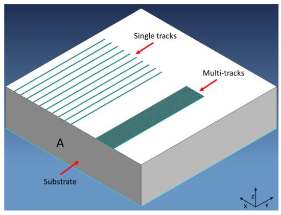
Figure 1.
Specimen geometry and features.
Additional thermal effects related to the heat induced by the preheating temperature due to the presence of a support structure or a change in cross-section during component printing that can result in weakening and imbalance of thermal conduction are not investigated in this work. In fact, the specimens used for both case studies have constant cross-sectional area and consequently no variation in the thermal history of the part during the printing process.
A Renishaw Quantam Software (Version 5.3.0.7105, Wotton-under-Edge, UK) is used to create the build file considering the process parameters and the laser assignment.
A wire EDM machine (ECUT EU MS Genesi, Desio, Italy) is used to detach the specimens from the building platform. Each specimen is prepared for micrographic analysis through the following steps according to ASTM E407-07 and ASTM E3-11 [44,45]: each specimen is cut along face A (Figure 1) at a distance from the edge (A) of 4 mm using a Struers Secotom-20 machine (Struers, Ballerup, Denmark) to obtain a proper section to be analyzed. This operation turns out to be necessary in order to avoid edge effects and to analyze a melt pool in its steady-state condition. The specimen section is then embedded in a conductive resin using a Struers CitoPress-30 machine. In the next step the specimen’s surface is polished using a Struers Tegramin-30 machine. Finally, in order to highlight the melt pool boundaries, the specimens were etched with oxalic acid.
The following melt pool shape analysis is carried out using a Leica Leitz DMRME optical microscope (Leica Microsystems GmbH, Wetzlar, Germany) following the indications and procedure defined in [38]:
- -
- The single tracks analysis is performed through the measurement in five random tracks of the melt pool width and depth;
- -
- The multi-tracks analysis is performed by measuring the overlap depth and width of five random tracks.
3. Results
3.1. Study of Preheating Temperature Effect on 40 Microns Layered Specimens
Figure 2 shows the specimens after the printing before the detachment from the building platform.
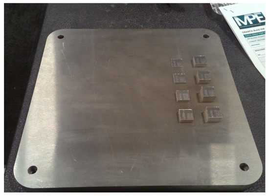
Figure 2.
Printed specimens and their position on the base plate.
3.1.1. Single Tracks Analysis
Table 5 and Figure 3 and Figure 4 show the results of the melt pool analysis of the single tracks in terms of depth, width, and of the ratios width/depth and depth/thickness.
Table 5.
Melt pool analysis tracking table.
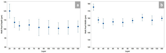
Figure 3.
Melt pool analysis of single tracks in terms of depth (a) and width (b).
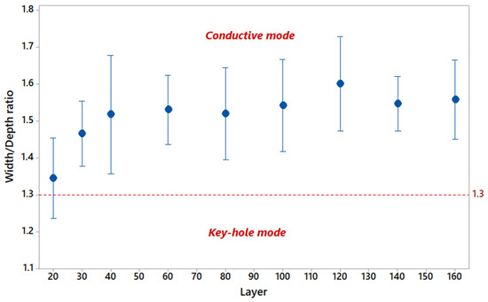
Figure 4.
Width/depth ratio as a function of the number of layers. The red dotted line identifies the threshold value of the width/depth ratio; below that value, the melt pool formation is considered governed by the keyhole melting mode.
Figure 5 shows the change in the melt pool as a function of the distance of single tracks from the building platform.
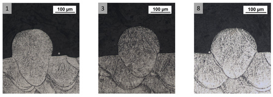
Figure 5.
Melt pool shape variation as a function of the number of layers. Specimen (1) is characterized by an elongated melt pool shape peculiar of the keyhole melting regime, while the melt pool of specimens (3) and (8) has a semi-elliptical shape indicating that the melt pool formation is governed by conduction.
3.1.2. Multi-Tracks Analysis
Table 6 shows the results of measuring the overlap area and of the analyzed multi-tracks.
Table 6.
Multi-tracks analysis tracking table of 40 Microns Layered Specimens.
Figure 6 and Figure 7 plot the results of the melt pool analysis of multi-tracks in terms of overlap depth, width and width tracks average.
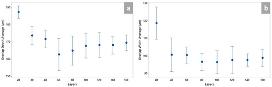
Figure 6.
Melt pool analysis of the multi-tracks in terms of overlap depth (a) and width (b) as a function of number of layers.
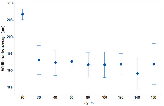
Figure 7.
Width track average of multi-tracks as a function of the number of layers.
Figure 8 shows the overlap region shape variation as a function of the distance of multi-tracks from the building platform.
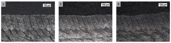
Figure 8.
Width of multi-tracks as a function of the number of layers. Specimen (1) is characterized by wide and depth melt pools confirming the contribution of the keyhole regime during the melt pool formation. On the other hand, by the evaluation of the melt pool shape for specimen (3) and specimen (8), it is possible to rule out that this melting regime contributes to these configurations.
3.2. Study of Preheating Temperature Effect on 60 Microns Layered Specimens
Table 7.
Melt pool depth, width, width/depth and depth/thickness tracking table.
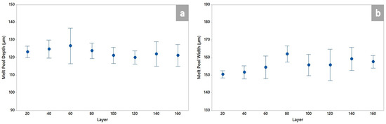
Figure 9.
Melt pool depth (a) and width (b) as a function of the number of layers.
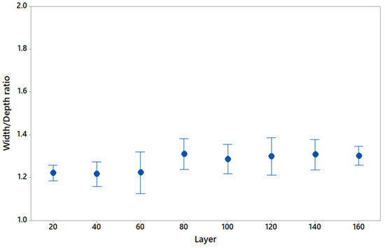
Figure 10.
Width/depth ratio as a function of the number of layers.
Figure 11 shows the melt pool shape variation as a function of the distance of single tracks from the building platform.
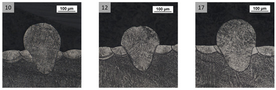
Figure 11.
Melt pool shape as a function of the number of layers. The melt pool shape analyzed for each specimen is similar in shape for all the configurations; no remarkable differences are observed between specimens 10, 12 and 17.
Table 8 presents the results of the measurement of the overlap region and widths of the analyzed multi-tracks.
Table 8.
Multi-tracks analysis tracking table of 60 Microns Layered Specimens.

Figure 12.
Overlap depth (a) and width (b) as a function of the number of layers.
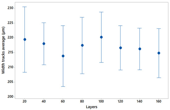
Figure 13.
Width of multi-tracks as a function of the number of layers.
Figure 14 shows the overlap region shape as a function of the distance of multi-tracks from the building platform.
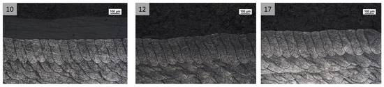
Figure 14.
Multi-tracks shape as a function of the number of layers. No remarkable differences are appreciated in melt pools shape as a function of the analyzed specimen except for the overlap width that in the specimen (10) turns out to be quite larger compared to the other configurations (12 and 17).
4. Discussion
4.1. Study of Preheating Temperature Effect on 40 Microns Layered Specimens
After evaluating the results of the melt pool analysis for single tracks shown in Table 5 and Figure 4 and Figure 5, it is possible to observe that Sample 1 has a deeper melt pool than the other configurations. In particular, the melt pool depth of configuration 1 is 15% larger than the average of the other configurations. In addition, the analysis of the width/depth ratio shows that the formation of the melt pool in this configuration is not entirely governed by conduction, but there is also a contribution of the keyhole melting regime. Moreover, this theory is confirmed by the images of the melt pool shape shown in Figure 6, where it can be seen that the melt pool shape of Sample 1 is quite far from the semi-elliptical shape associated with the conductive melting regime.
Furthermore, it can be observed from the multi-tracks analysis results, which are tracked in Table 6 and shown in Figure 6, Figure 7 and Figure 8, that configuration 1 has a significantly larger overlap region in terms of depth and width than the other configurations. In fact, in terms of overlap depth, width and multi-tracks width, this configuration results are greater by 12%, 20% and 7%, respectively, compared to the average of the other configurations.
These findings lead to the printing of a specimen with a substrate height of 30 layers in order to investigate the range of 20 to 40 layers. This configuration, in terms of melt pool depth and width, is aligned with the configurations with a substrate height over 40 layers, as shown in Table 5. This trend is also confirmed by melt pool analysis of multi-tracks.
Consequently, it is feasible to conclude that the preheating temperature of the building platform has an impact on the melt pool formation in configuration 1 based on a thorough review of the single and multi-tracks analysis results.
As a result of the existence of keyhole porosity defects in the layers before those evaluated for configuration 1—that is, at a distance of 30 layers from the building platform—is possible because the melt pool formation is not completely governed by conduction. Therefore, with the studied material and layer thickness, it is recommended to avoid making components with fewer than 30 layers of powder.
4.2. Study of Preheating Temperature Effect on 60 Microns Layered Specimens
The evaluation of the results of the melt pool analysis for single tracks, shown in Table 7 and Figure 9, Figure 10 and Figure 11, indicates that there are no significant differences in melt depth and width between the tested configurations. Even if the conduction does not entirely govern the melt pool formation, this is probably due to the high-energy process parameters used for this case study (Table 3).
In addition, considering the results of the analysis of multi-tracks, as shown in Table 8 and Figure 12, Figure 13 and Figure 14, no appreciable variation in terms of overlap depth and width and in terms of melt pool width are observed.
Thus, based on these results, it can be concluded that the melt pool in the range of layers investigated in this case study is not affected by the effects of the preheating temperature, and the results are stable.
This outcome is very interesting for a proper Design for Additive Manufacturing because it highlights how the minimal distance from the building platform necessary to avoid any effect of preheating temperature is independent on the layers’ thickness used to build the component.
In particular, by evaluating the results of the 40- and 60-micron case studies discussed previously, it is possible to determine that the instability of the melt pool is not found at a substrate height greater than 1.2 mm. Consequently, it is recommended to print a few layers of height parts with a sacrificial substrate of at least 1.2 mm height.
5. Conclusions
This paper investigates the effect of the preheating temperature on the stability of the melt pool. The results show how the number of layers has an important role in obtaining the melt pool’s stability in both depth and width. The overall analysis of the results of the two case studies carried out in this paper shows and highlights, in particular, that the first layers of the printing material are affected by the effects of the preheating temperature of the building platform. The effect of preheating temperature on the material microstructure is evaluated by the analysis of the melt pool, which shows that the melt pool in both case studies reaches its stability after a distance of 1.2 mm from the building platform. The results obtained also show that this effect is independent of the layer thickness used during the printing process, but it depends only on the distance from the building platform.
These results are of great importance, as they allow the identification of an internal process criticality, the knowledge of which enables the correct design of components with a size of a few hundred microns, which is becoming increasingly important for industries working in the micrometer-sized components market.
Based on the findings presented in this paper, it is possible to summarize that the use of a thin sacrificial substrate (at least 1.2 mm height in our case study) will help ensure a stable powder melting regime and, as a result, an adequate material microstructure on IN718 components manufactured through the L-PBF process.
Author Contributions
Conceptualization, N.B., A.G., M.P. and P.C.; Data curation, N.B. and A.G.; Formal analysis, N.B. and A.G.; Funding acquisition, I.G. and P.C.; Investigation, N.B. and A.G.; Methodology, N.B., A.G. and M.P.; Project administration, I.G.; Resources, M.P.; Software, N.B. and A.G.; Supervision, I.G., G.A. and P.C.; Validation, M.P. and I.G.; Visualization, N.B. and A.G.; Writing—original draft, N.B., A.G. and M.P.; Writing—review and editing, N.B., A.G., M.P. and G.A. All authors have read and agreed to the published version of the manuscript.
Funding
This research received no external funding.
Data Availability Statement
Not applicable.
Conflicts of Interest
The authors declare no conflict of interest.
References
- Wang, Z.; Guan, K.; Gao, M.; Li, X.; Chen, X.; Zeng, X. The microstructure and mechanical properties of deposited-IN718 by selective laser melting. J. Alloys Compd. 2012, 513, 518–523. [Google Scholar] [CrossRef]
- Das, S. Physical aspects of process control in selective laser sintering of metals. Adv. Eng. Mater. 2003, 5, 701–711. [Google Scholar] [CrossRef]
- Osakada, K.; Shiomi, M. Flexible manufacturing of metallic products by selective laser melting of powder. Int. J. Mach. Tools Manuf. 2006, 46, 1188–1193. [Google Scholar] [CrossRef]
- Kruth, J.P.; Mercelis, P.; Van Vaerenbergh, J.; Froyen, L.; Rombouts, M. Binding mechanisms in selective laser sintering and selective laser melting. Rapid Prototyp. J. 2005, 11, 26–36. [Google Scholar] [CrossRef]
- Yadroitsev, I.; Gusarov, A.; Yadroitsava, I.; Smurov, I. Single track formation in selective laser melting of metal powders. J. Mater. Process. Technol. 2010, 210, 1624–1631. [Google Scholar] [CrossRef]
- Gu, D.D.; Meiners, W.; Wissenbach, K.; Poprawe, R. Laser additive manufacturing of ceramic components: Materials, processes, and mechanisms. Laser Addit. Manuf. Mater. Des. Technol. Appl. 2016, 6608, 163–180. [Google Scholar]
- Smith, J.; Xiong, W.; Yan, W.; Lin, S.; Cheng, P.; Kafka, O.L.; Wagner, G.J.; Cao, J.; Liu, W.K. Linking process, structure, property, and performance for metal-based additive manufacturing: Computational approaches with experimental support. Comput. Mech. 2016, 57, 583–610. [Google Scholar] [CrossRef]
- Metelkova, J.; Kinds, Y.; Kempen, K.; De Formanoir, C.; Witvrouw, A.; Van Hooreweder, B. On the influence of laser defocusing in Selective Laser Melting of 316L. Addit. Manuf. 2018, 23, 161–169. [Google Scholar] [CrossRef]
- Ceccanti, F.; Giorgetti, A.; Arcidiacono, G.; Citti, P. Laser Powder Bed Fusion: A Review on the Design Constraints. IOP Conf. Ser. Mater. Sci. Eng. 2021, 1038, 012065. [Google Scholar] [CrossRef]
- Singh, S.N.; Chowdhury, S.; Nirsanametla, Y.; Deepati, A.K.; Prakash, C.; Singh, S.; Wu, L.Y.; Zheng, H.Y.; Pruncu, C. A Comparative Analysis of Laser Additive Manufacturing of High Layer Thickness Pure Ti and Inconel 718 Alloy Materials Using Finite Element Method. Materials 2021, 14, 876. [Google Scholar] [CrossRef] [PubMed]
- Yadroitsev, I.; Yadroitsava, I. A step-by-step guide to the L-PBF process. In Fundamentals of Laser Powder Bed Fusion of Metals; Elsevier: Amsterdam, The Netherlands, 2021. [Google Scholar]
- Ciappi, A.; Giorgetti, A.; Ceccanti, F.; Canegallo, G. Technological and economical consideration for turbine blade tip restoration through metal deposition technologies. Proc. Inst. Mech. Eng. Part C J. Mech. Eng. Sci. 2021, 235, 1741–1758. [Google Scholar] [CrossRef]
- Cobbinah, P.V.; Nzeukou, R.A.; Onawale, O.T.; Matizamhuka, W.R. Laser Powder Bed Fusion of Potential Superalloys: A Review. Metals 2021, 11, 58. [Google Scholar] [CrossRef]
- Abd-Elaziem, W.; Elkatatny, S.; Abd-Elaziem, A.; Khedr, M.; El-baky, M.A.A.; Hassan, M.A.; Abu-Okail, M.; Mohammed, M.; Järvenpää, A.; Allam, T.; et al. On the current research progress of metallic materials fabricated by laser powder bed fusion process: A review. J. Mater. Res. Technol. 2022, 20, 681–707. [Google Scholar] [CrossRef]
- Ceccanti, F.; Giorgetti, A.; Citti, P. A support structure design strategy for laser powder bed fused parts. Procedia Struct. Integr. 2019, 24, 667–679. [Google Scholar] [CrossRef]
- Khan, H.M.; Karabulut, Y.; Kitay, O.; Kaynak, Y.; Jawahir, I.S. Influence of the post-processing operations on surface integrity of metal components produced by laser powder bed fusion additive manufacturing: A review. Mach. Sci. Technol. 2021, 25, 118–176. [Google Scholar] [CrossRef]
- Mostafaei, A.; Zhao, C.; He, Y.; Ghiaasiaan, S.R.; Shi, B.; Shao, S.; Shamsaei, N.; Wu, Z.; Kouraytem, N.; Sun, T.; et al. Defects and anomalies in powder bed fusion metal additive manufacturing. Curr. Opin. Solid State Mater. Sci. 2022, 26, 100974. [Google Scholar] [CrossRef]
- Makona, N.W.; Yadroitsava, I.; Moller, H.; Tlotleng, M.; Yadroitsev, I. Evaluation of single tracks of 17-4PH steel manufactured at different power densities and scanning speeds by selective laser melting. S. Afr. J. Ind. Eng. 2016, 27, 210–218. [Google Scholar] [CrossRef][Green Version]
- Liu, X.; Wang, K.; Hu, P.; He, X.; Yan, B.; Zhao, X. Formability, Microstructure and Properties of Inconel 718 Superalloy Fabricated by Selective Laser Melting Additive Manufacture Technology. Materials 2021, 14, 991. [Google Scholar] [CrossRef] [PubMed]
- Blakey-Milner, B.; Gradl, P.; Snedden, G.; Brooks, M.; Pitot, J.; Lopez, E.; Leary, M.; Berto, F.; Du Plessis, A. Metal additive manufacturing in aerospace: A review. Mater. Des. 2021, 209, 110008. [Google Scholar] [CrossRef]
- Bidulsky, R.; Gobber, F.S.; Bidulska, J.; Ceroni, M.; Kvackaj, T.; Grande, M.A. Coated Metal Powders for Laser Powder Bed Fusion (L-PBF) Processing: A Review. Metals 2021, 11, 1831. [Google Scholar] [CrossRef]
- Mahmoud, D.; Magolon, M.; Boer, J.; Elbestawi, M.A.; Mohammadi, M.G. Applications of Machine Learning in Process Monitoring and Controls of L-PBF Additive Manufacturing: A Review. Appl. Sci. 2021, 21, 11910. [Google Scholar] [CrossRef]
- Chen, Q.; Zhao, Y.; Strayer, S.; Zhao, Y.; Aoyagi, K.; Koizumi, Y.; Chiba, A.; Xiong, W.; To, A.C. Elucidating the effect of preheating temperature on melt pool morphology variation in Inconel 718 laser powder bed fusion via simulation and experiment. Addit. Manuf. 2021, 37, 101642. [Google Scholar] [CrossRef]
- Panahi, N.; Åsberg, M.; Oikonomou, C.; Krakhmalev, P. Effect of preheating temperature on the porosity and microstructure of martensitic hot work tool steel manufactured with L-PBF. Procedia CIRP 2022, 111, 166–170. [Google Scholar] [CrossRef]
- Polozov, I.; Sufiiarov, V.; Kantyukov, A.; Razumov, N.; Goncharov, I.; Makhmutov, T.; Silin, A.; Kim, A.; Starikov, K.; Shamshurin, A. Microstructure, densification, and mechanical properties of titanium intermetallic alloy manufactured by laser powder bed fusion additive manufacturing with high-temperature preheating using gas atomized and mechanically alloyed plasma spheroidized powders. Addit. Manuf. 2020, 34, 101374. [Google Scholar] [CrossRef]
- Ahmadi, M.; Tabary, S.B.; Rahmatabadi, D.; Ebrahimi, M.S.; Abrinia, K.; Hashemi, R. Review of Selective Laser Melting of Magnesium Alloys: Advantages, Microstructure and Mechanical Characterizations, Defects, Challenges, and Applications. J. Mater. Res. Technol. 2022, 19, 1537–1562. [Google Scholar] [CrossRef]
- Li, S.; Xiao, H.; Liu, K.; Xiao, W.; Li, Y.; Han, X.; Song, J.M.L. Melt-pool motion, temperature variation and dendritic morphology of Inconel 718 during pulsed- and continuous-wave laser additive manufacturing: A comparative study. Mater. Des. 2017, 119, 351–360. [Google Scholar] [CrossRef]
- Childs, T.H.C.; Hauser, C.; Badrossamay, M. Mapping and Modelling Single Scan Track Formation in Direct Metal Selective Laser Melting. CIRP Ann. 2004, 53, 191–194. [Google Scholar] [CrossRef]
- Guo, Y.; Jia, L.; Kong, B.; Wang, N.; Zhang, H. Single track and single layer formation in selective laser melting of niobium solid solution alloy. Chin. J. Aeronaut. 2018, 31, 860–866. [Google Scholar] [CrossRef]
- Shrestha, S.; Chou, K. Single track scanning experiment in laser powder bed fusion process. Procedia Manuf. 2018, 26, 857–864. [Google Scholar] [CrossRef]
- Yadroitsava, I.; Els, J.; Booysen, G.; Yadroitsev, I. Peculiarities of single track formation from Ti6AL4V alloy at different laser power densities by selective laser melting. S. Afr. J. Ind. Eng. 2015, 26, 86–95. [Google Scholar] [CrossRef]
- Zheng, H.; Wang, Y.; Xie, Y.; Yang, S.; Hou, R.; Ge, Y.; Lang, L.; Gong, S.; Li, H. Observation of Vapor Plume Behavior and Process Stability at Single-Track and Multi-Track Levels in Laser Powder Bed Fusion Regime. Metals 2021, 11, 937. [Google Scholar] [CrossRef]
- Johnson, L.; Mahmoudi, M.; Zhang, B.; Seede, R.; Huang, X.; Maier, J.T.; Maier, H.J.; Karaman, I.; Elwany, A.; Arróyave, R. Assessing printability maps in additive manufacturing of metal alloys. Acta Mater. 2019, 176, 199–210. [Google Scholar] [CrossRef]
- Tenbrock, C.; Fischer, F.G.; Wissenbach, K.; Schleifenbaum, J.H.; Wagenblast, P.; Meiners, W.; Wagner, J. Influence of keyhole and conduction mode melting for top-hat shaped beam profiles in laser powder bed fusion. J. Mater. Process. Technol. 2020, 278, 116514. [Google Scholar] [CrossRef]
- King, W.A.; Barth, H.D.; Castillo, V.M.; Gallegos, G.F.; Gibbs, J.W.; Hahn, D.E.; Kamath, C.; Rubenchik, A.M. Observation of keyhole-mode laser melting in laser powder-bed fusion additive manufacturing. J. Mater. Process. Technol. 2014, 214, 2915–2925. [Google Scholar] [CrossRef]
- Tian, Y.; Tomus, D.; Rometsch, P.; Wu, X. Influences of processing parameters on surface roughness of Hastelloy X produced by selective laser melting. Addit. Manuf. 2017, 13, 103–112. [Google Scholar] [CrossRef]
- Ning, J.; Wang, W.; Zamorano, B.; Liang, S.Y. Analytical modeling of lack-of-fusion porosity in metal additive manufacturing. Appl. Phys. 2019, 125, 797. [Google Scholar] [CrossRef]
- Mukherjee, T.; DebRoy, T. Mitigation of lack of fusion defects in powder bed fusion additive manufacturing. J. Manuf. Process. 2018, 36, 442–449. [Google Scholar] [CrossRef]
- Giorgetti, A.; Baldi, N.; Palladino, M.; Ceccanti, F.; Arcidiacono, G.; Citti, P. A Method to Optimize Parameters Development in L-PBF Based on Single and Multitracks Analysis: A Case Study on Inconel 718 Alloy. Metals 2023, 13, 306. [Google Scholar] [CrossRef]
- Baldi, N.; Giorgetti, A.; Palladino, M.; Giovannetti, I.; Arcidiacono, G.; Citti, P. Study on the Effect of Inter-Layer Cooling Time on Porosity and Melt Pool in Inconel 718 Components Processed by Laser Powder Bed Fusion. Materials 2023, 16, 3920. [Google Scholar] [CrossRef] [PubMed]
- Altin, A.; Nalbant, M.; Taskesen, A. The effects of cutting speed on tool wear and tool life when machining Inconel 718 with ceramic tools. Mater. Des. 2007, 28, 2518–2522. [Google Scholar] [CrossRef]
- Watring, D.S.; Carter, K.C.; Crouse, D.; Raeymaekers, B.; Spear, A.D. Mechanisms driving high-cycle fatigue life of as-built Inconel 718 processed by laser powder bed fusion. Mater. Sci. Eng. A 2019, 761, 137993. [Google Scholar] [CrossRef]
- Balbaa, M.; Mekhiel, S.; Elbestawi, M.; McIsaac, J. On Selective laser melting of Inconel 718: Densification, surface roughness, and residual stresses. Mater. Des. 2020, 193, 108818. [Google Scholar] [CrossRef]
- ASTM E407-07; Standard Practice for Microetching Metals and Alloys. ASTM International: West Conshohocken, PA, USA, 2015; p. e1.
- ASTM E3-11; Standard Guide for Preparation of Metallographic Specimens. ASTM International: West Conshohocken, PA, USA, 2017.


Disclaimer/Publisher’s Note: The statements, opinions and data contained in all publications are solely those of the individual author(s) and contributor(s) and not of MDPI and/or the editor(s). MDPI and/or the editor(s) disclaim responsibility for any injury to people or property resulting from any ideas, methods, instructions or products referred to in the content. |
© 2023 by the authors. Licensee MDPI, Basel, Switzerland. This article is an open access article distributed under the terms and conditions of the Creative Commons Attribution (CC BY) license (https://creativecommons.org/licenses/by/4.0/).