Abstract
Additive manufacturing (AM) processes are playing a significant role in several industrial sectors such as construction and machine building industries, involving a wide variety of metallic materials. Among these, the AM of aluminium alloys has developed significantly over the last decade, mainly through Powder Bed Fusion (PBF) and Directed Energy Deposition (DED) processes. Despite the many advantages of AM technology, some large or complex products cannot be produced entirely without the use of conventional manufacturing and joining processes, generally for financial or operational reasons. In this way, the ability to join conventionally and additively manufactured components or parts represents a crucial step towards their future use and the consolidation of conventional and additive manufacturing technologies. Despite the growing interest in AM technologies, there is still a significant lack of information on the joining of conventionally and additively manufactured components. The present work proposes a first review of the literature evaluating the weldability of AM aluminium alloys. The focus is on the use of fusion and solid-state welding processes and analysing the achieved microstructural evolution and mechanical properties. A clear relationship is observed between the AM technology used to produce the part, and the physical principles of the joining process. In addition, the gaps in the literature are highlighted to enable focused future work.
1. Introduction
Additive manufacturing (AM) technology has evolved steadily over the last decade to overcome the challenges and operational and financial drawbacks associated with conventional manufacturing processes. AM is a tool-less, near-net-shape production technology, based on three-dimensional (3D) model data [1]. This new type of processing has provided industries with unprecedented opportunities to produce metal components with complex free-form geometries, where such geometries are not achievable using conventional manufacturing techniques [2,3].
Among the various types of AM processes for manufacturing metallic components, two groups are highlighted as the most promising for industrial applications: Powder Bed Fusion (PBF) and Directed Energy Deposition (DED) processes. Although there may be similarities between the two groups, such as the possibility of using powder as feedstock material, and although some processes of both groups can use the same heat source, such as a laser or an electron beam, there are clear advantages and limitations associated with this division.
On the one hand, PBF processes are well known for their ability to produce extremely complex parts with high geometric accuracy but are limited in size by the build chamber. On the other hand, DED produces parts that are virtually unlimited in size, as the manufacturing process can still be mounted on a moving rail, but DED is limited regarding the geometrical complexity.
However, despite the many advantages of AM technology, it is not always feasible to produce a large or complex product without conventional manufacturing or joining processes, either for financial or operational reasons. In this way, the ability to join conventionally and additively manufactured components or parts represents a crucial step towards their future use and consolidation of conventional and additive manufacturing technologies. Despite the growing interest in AM technologies, there is still a significant lack of knowledge on the joining of conventionally and additively manufactured components.
This review reports on the weldability of additively manufactured Al alloys by fusion and solid-state welding processes, providing an overview of the relevant AM processes. The challenges for the weldability of conventionally and additively manufactured Al alloys will be addressed in the next sections. This work provides an overview of the advantages and limitations of each group of welding processes and highlights the gaps in the literature.
2. Additive Manufacturing Processes and Microstructures
ASTM has standardised and categorised metal AM processes according to feedstock, state of material during processing, material distribution, and basic technology principles (e.g., heat source) in ISO/ASTM 529000:2021 [4]. As this article focuses on the weldability investigation of AM aluminium alloys, only AM processes based on Laser Powder Bed Fusion (PBF-LB) and Arc Wire Directed Energy Deposition (DED-Arc) will be considered. The PBF process using an electron beam (PBF-EB) is not used for manufacturing parts made of Al alloys, and therefore it will not be addressed in this work.
PBF produces parts by fusion of powder feedstock using a laser beam (PBF-LB) as a heat source. The beam melts or sinters the material according to a defined scan strategy, to create features within a discrete layer. The chamber is purged and a recoater arm provides a new layer of powder to be fused in a layer-by-layer process to create the final part. PBF-LB is also known as selective laser melting (SLM™) [5], direct metal laser sintering (DMLS™) [6], and direct metal laser melting (DMLM) [7].
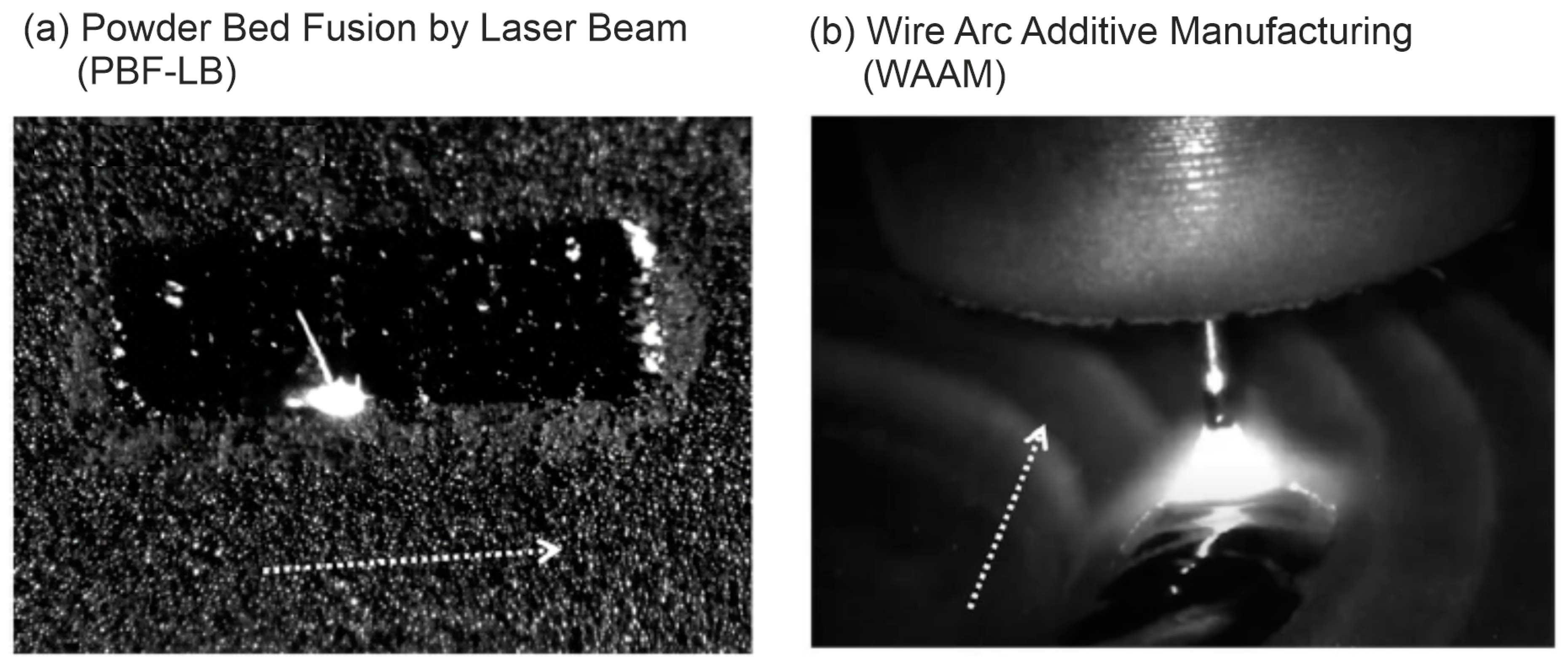
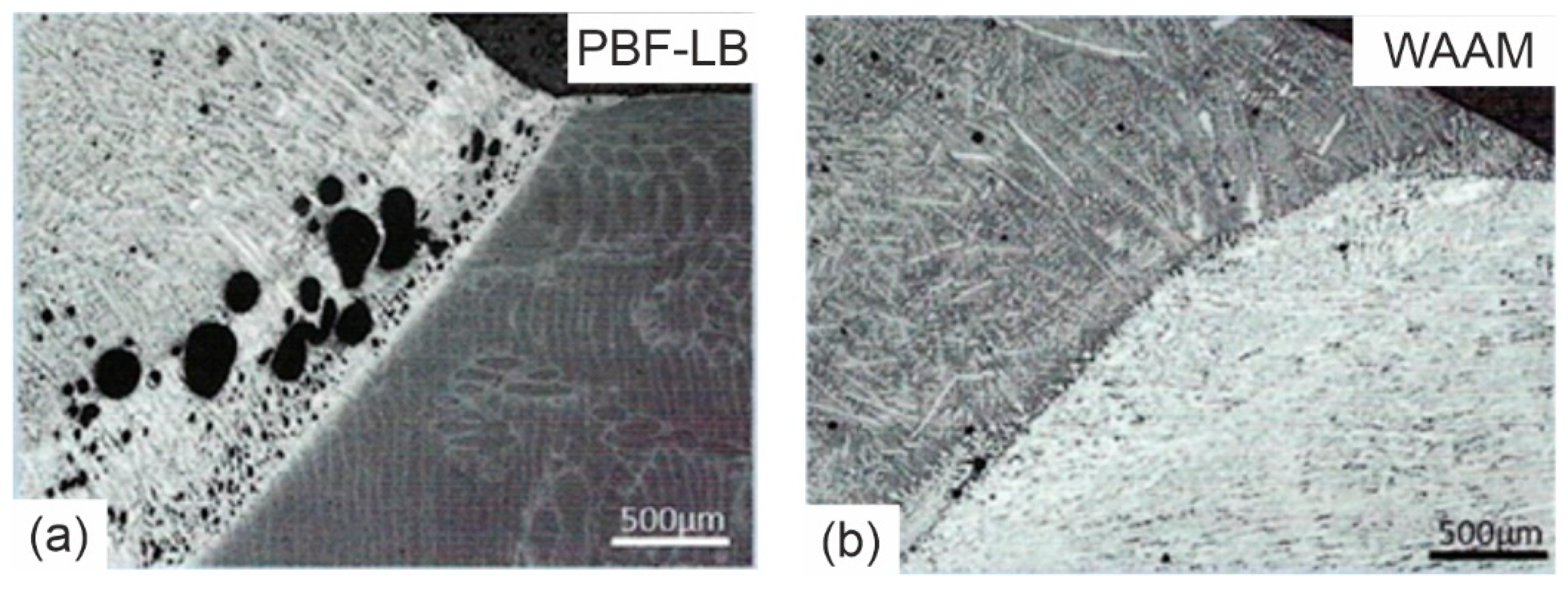
Directed Energy Deposition (DED) processes, as the name suggests, use directed energy in combination with a directed feed of material to be melted and solidified according to a specific deposition path strategy. In this case, the feed materials are usually in powder or wire form. DED-Arc is most referred to by academia and industry as Wire Arc Additive Manufacturing (WAAM). Due to common usage, this nomenclature will be adopted for this work. However, WAAM is not a single process, but a group of AM processes that use an electric arc as the heat source and wire as feedstock. In this sense, four individual WAAM processes are reported in the literature. More specifically, the processes based on gas metal arc welding (WAAM-GMAW), gas tungsten arc welding (WAAM-GTAW), plasma arc welding (WAAM-PAW), and submerged arc welding (WAAM-SAW) [8]. WAAM-GMAW is the most widely used; WAAM-SAW is only seen in very specific applications. Visuals of the two AM processes considered in this paper, PBF-LB and WAAM, are shown in Figure 1.

Figure 1.
Close-up images of PBF-LB (a) and WAAM (b) processes along with the deposition direction (adapted from [9]).
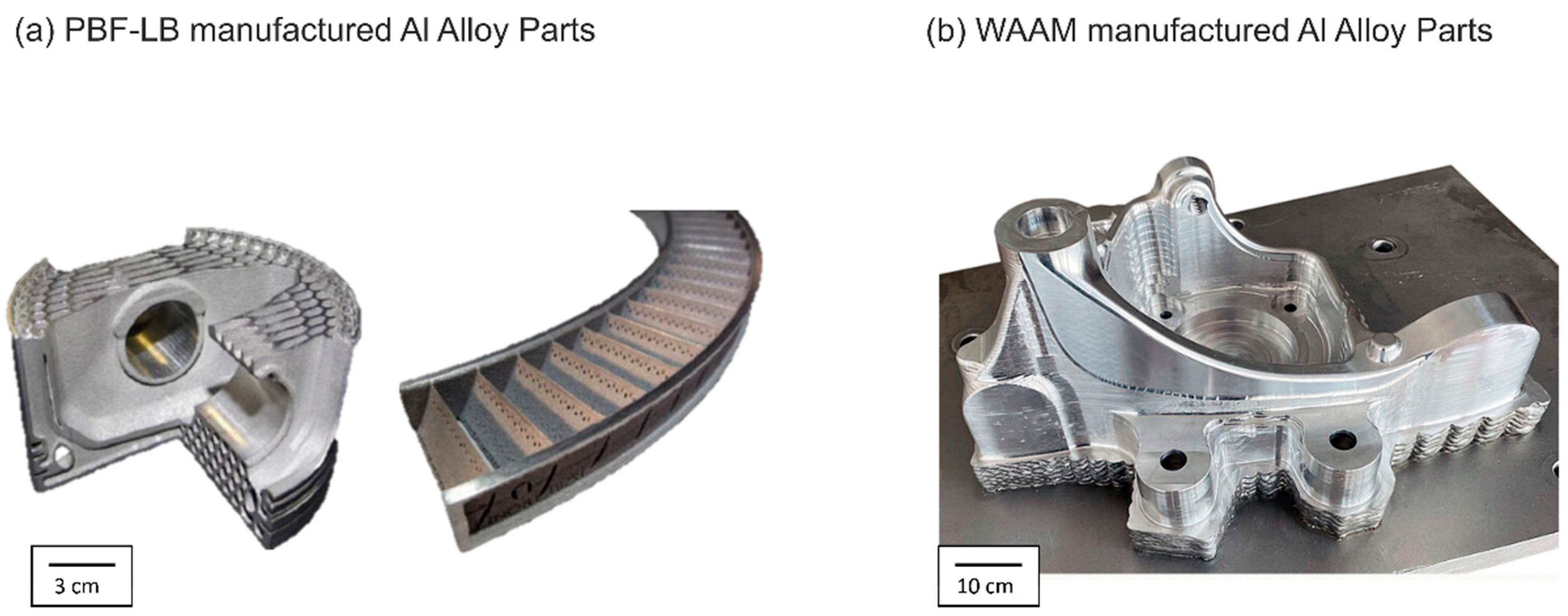
Although there are several advantages and limitations associated with these two major AM groups (PBF and DED), such as the cost of equipment and raw materials and the level of industrial maturity, the most important selection criteria for the manufacturing of Al parts are the dimensional printing limitations and the complexity of the desired part, as illustrated in Figure 2.
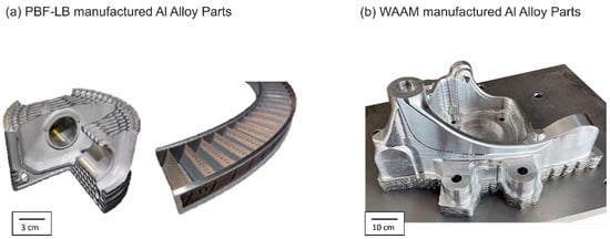
Figure 2.
Aluminium parts manufactured by PBF-LB (a) and WAAM (b) processes. At the left, ER 2024 and ER 6061 aluminium parts manufactured by Elementum 3D (adapated from [10]). At the right, an ER 5183 aluminium part manufactured by Migal (adapated from [11]).
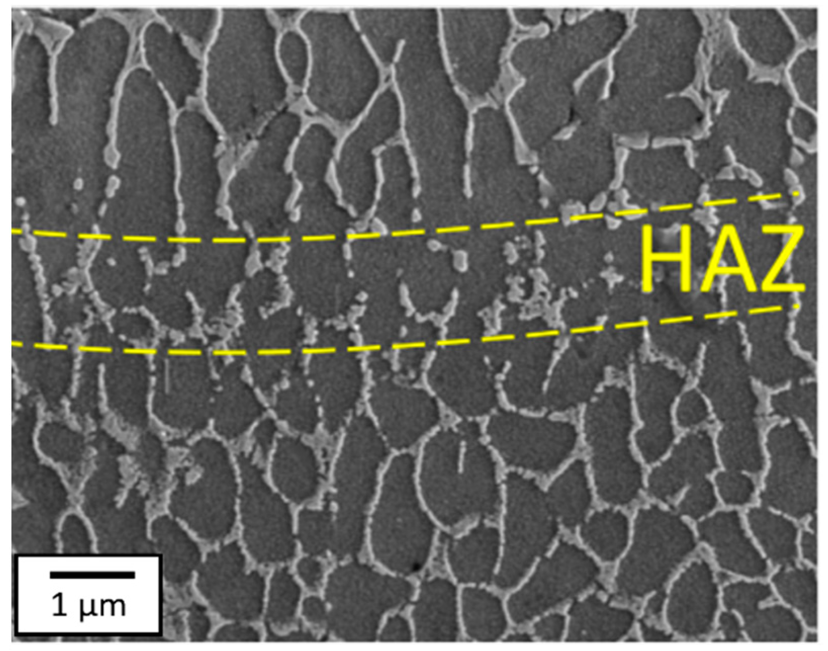
The microstructure of PBF-LB manufactured Al alloys generally consists of elongated and equiaxed grains, the size of which depends on the cooling rate during the process. A higher cooling rate means rapid solidification and therefore small grains. The cooling rate of AM processes, such as PBF-LB, is generally much higher than that of casting processes [12] and can be controlled by changing the process parameters. The direction of the cooling rate also influences the directional growth of the elongated particles [13,14]. The most common imperfections in the finished material are inclusions and porosity. Porosity can be the result of gas inclusions or lack of fusion due to insufficient melting [15]. The microstructure of PBF-LB AlSi10Mg is shown in Figure 3 where zones of coarse and fine grains are found due to different cooling rates.

Figure 3.
Scanning Electron Microscope (SEM) micrographs of the HAZ zone (in between the two yellow dashed lines) of a PBF-LB AlSi10Mg alloy (adapted from [15]).
Due to the very different thermal cycles in the WAAM process, there are limited similarities between the microstructures produced by WAAM and PBF-LB. Figure 4 shows the microstructure found in the inlayer regions of alloy ER 5356 produced by WAAM. The interlayer, which is the interface region between two deposited layers, is mainly composed of finely structured equiaxed grains, and micropores are often distributed near these grains. These micropores play a significant role in reducing the mechanical properties of the material near the interlayer as compared to the inner layer [16]. It is worth mentioning that the manufacturing shown in Figure 4 did not produce the same width for all layers. This aspect will have a significant influence on the cooling behaviour, which will affect the formed microstructure as well.
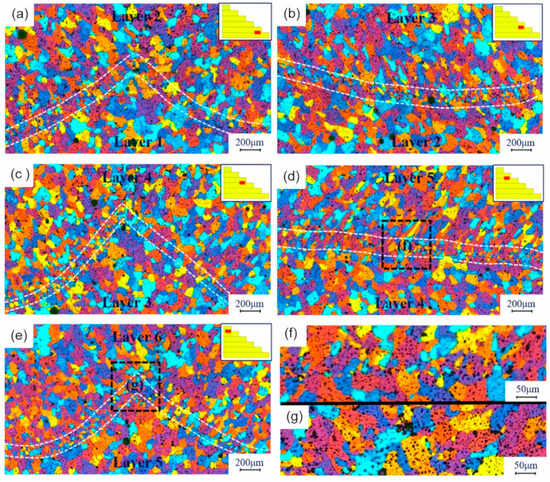
Figure 4.
Interlayer microstructures of a WAAM ER 5356 component: (a) 1st interface, (b) 2nd interface, (c) 3rd interface, (d) 4th interface, (e) 5th interface, (f) flat interlayer morphology, and (g) curved interlayer morphology [16].
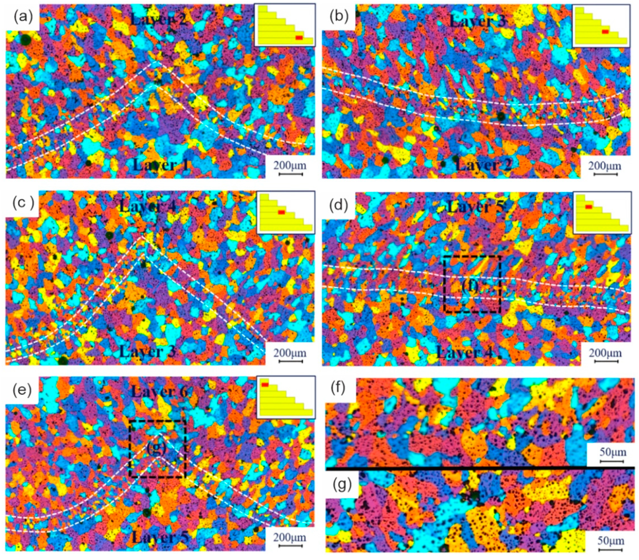
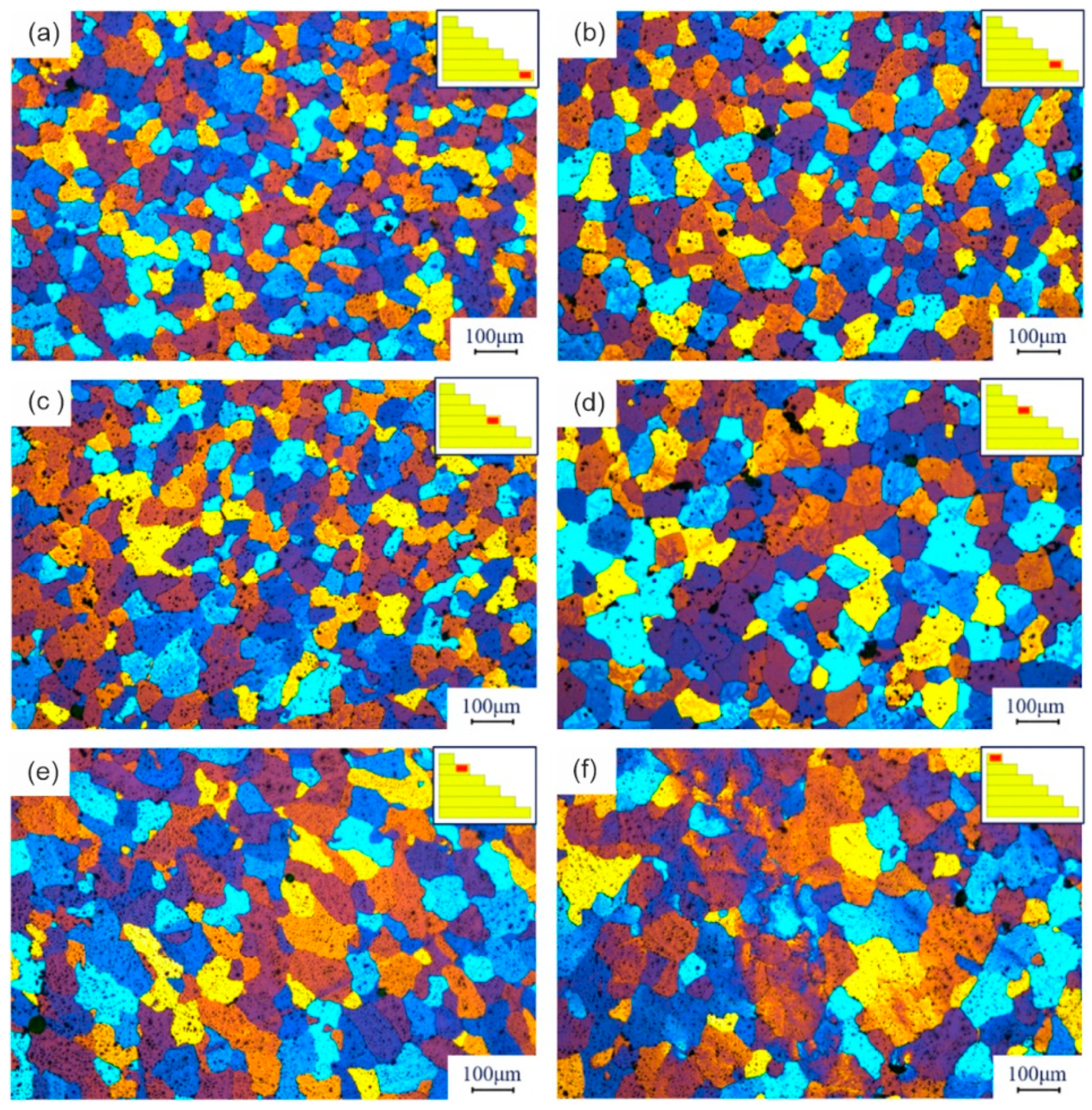
Figure 5 reveals that the microstructure of the lower region (region of the first 6 deposited layers) is dominated by equiaxed grains with small diameters. The microstructure of the middle region is also dominated by elongated grains along the thermal gradient. The number of columnar grains and the size of the elongated grains are larger in the middle area than in the bottom area. The microstructure of the upper zone is significantly different from that of the lower zone. The grains are much larger, and the elongated grains grow into columnar grains, that grow towards the upper region [16]. Those differences in the microstructure are mainly due to the different heat dissipation during manufacturing.

Figure 5.
Inner layer grain structure of a WAAM AA5356 component: (a) 1st layer, (b) 2nd layer, (c) 3rd layer, (d) 4th layer, (e) 5th layer, and (f) 6th layer [16].
3. Challenges in Welding Aluminium Alloys
In this work, aspects of the microstructural and mechanical properties of aluminium parts produced by the above-mentioned AM processes are addressed, in order to understand their influence on the weldability and properties of the joint.
Aluminium alloys are well known for their welding challenges [14]. These challenges are mainly related to the thermal properties and the presence of some alloying elements that might evaporate during welding.
Aluminium has a high thermal conductivity (237 W(m∗K)). This property mainly affects fusion welding processes, where longer weld beads are produced [17]. At the start of welding, the material is cold, and due to its high thermal conductivity, the entire part is rapidly heated. During welding, if the process parameters are maintained, the previously satisfactory weld bead will exhibit excessive heating, resulting in extreme penetration and possibly burn-through [18]. To overcome this challenge, it is possible to pre-heat the material to be welded and control the electrical parameters during fusion welding.
In addition, aluminium’s high coefficient of thermal expansion can be associated with the formation of solidification cracks in the melt zone caused by the contraction of the solidifying liquid metal [17]. As the melt solidifies, the metal undergoes significant contraction. Meanwhile, in the adjacent regions (heat-affected zone and base metal), contraction is reduced because the temperatures reached are not as high, not even reaching liquid-solid transformation. As a result of these factors, tensile stresses develop in the weld metal, the magnitude of which increases with several factors, such as the thickness of the parts and the joint configuration. This defect, known as hot cracking, occurs in intergranular form at the end of solidification when the stresses are acting on the remaining liquid melt pool [17].
A defect that drastically reduces the weld quality is porosity, which is mainly due to the modification of the solubility of hydrogen in aluminium when melted (Figure 6). Indeed, when reaching the melting point of aluminium, the hydrogen solubility reaches 0.7 cm3/100 g, which is 19.4 times higher than the solubility in solid aluminium [19]. With rapid cooling of the melt during solidification, the now insoluble hydrogen cannot escape the melt pool in time and remains trapped, forming pores in the part. To avoid this defect, it is advisable to use controlled cooling after the welding process has been completed [20]. In addition, excellent part cleaning from any moisture might decrease the hydrogen content after conventional and additive manufacturing [21].
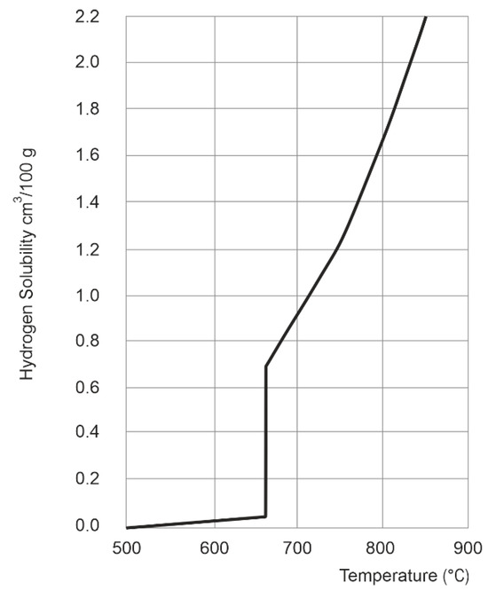
Figure 6.
Solubility of hydrogen in aluminium at varying temperatures.
Perhaps one of the most critical properties of aluminium with respect to welding processes is the presence of a passivation layer, consisting of an oxide on the surface of the aluminium alloy. This layer is characterized by low electrical conductivity and a high melting temperature [22]. Aluminium in its pure state has a melting point of 660 °C, while its oxide, alumina Al2O3, has a melting point of 2072 °C. This large difference necessitates prior cleaning of the surface to be welded to remove the excess of oxide present. The oxide layers can be removed in different ways depending on the type of welding process. In arc welding, for example, it is highly recommended to use the reversing polarity or alternating current to carry out the cathodic cleaning during the process itself [23].
Even when joining conventionally produced aluminium alloys, porosity is considered to be the most critical challenge, and techniques to reduce the porosity level and to improve the mechanical properties of joints have been reported in the literature, such as heat input control [24], use of dynamic wire feeding techniques for fusion welding processes [25], pre-heating [26], optimised process parameters [27,28], use of CO2 and He in the shielding gas mixture [29,30,31,32], higher quality control of the filler material [33] and laser cleaning of the parts to be welded prior to welding [34].
4. General Overview of the Reviewed Literature
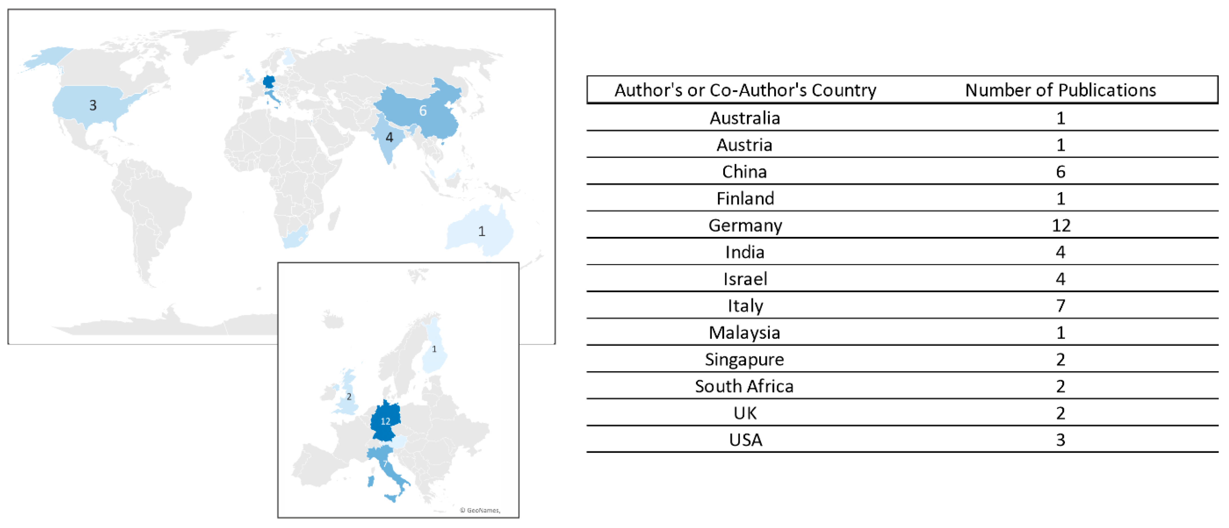
Although the joining of additively manufactured Al alloys is crucial to increase the use of these manufactured components in industrial applications, there is an obvious lack of information in the literature. At the time of writing, the authors retrieved only 39 articles published on the topic, in peer-reviewed journals, conference proceedings, and technical magazines. The literature review was conducted based on the “Web of Science” and “ScienceDirect” databases. Geographically, authors and co-authors are located in only 12 countries (Figure 7).
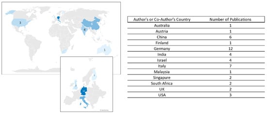
Figure 7.
Geographic distribution of author’s country of published articles evaluating the weldability of AM Al alloys.
To constrain the focus of this work to the welding between similar or dissimilar Al parts (involving at least one part manufactured by AM), the articles related to material processing, e.g., laser processing or friction stir processing, were excluded from this review.
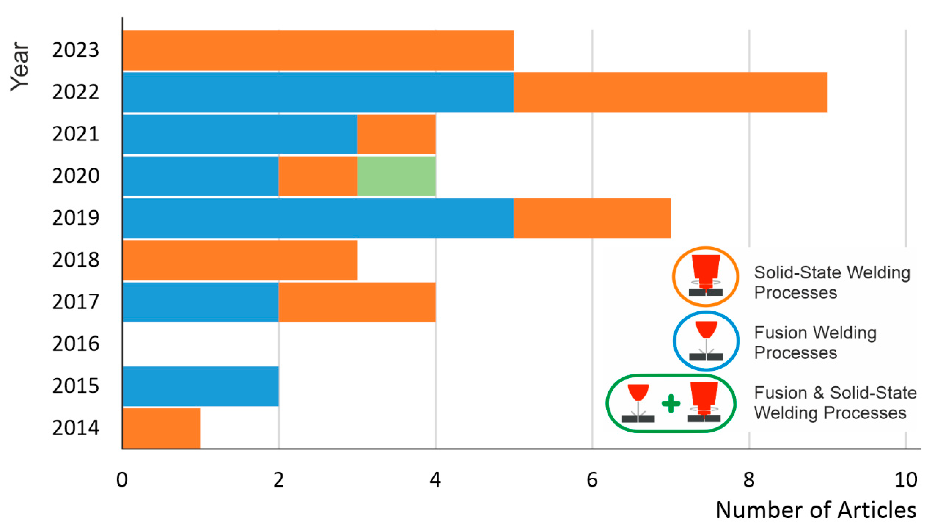
The aluminium alloys produced by AM show very different weldability when joined by fusion or solid-state welding processes. The general aspects related to the evolution of the microstructure and microhardness profile, mechanical properties, and typical challenges are presented in the following sections. However, only 1 article deals with a comparison between the two groups of welding processes. Figure 8 shows the evolution of the number of publications for the two groups of welding processes mentioned.
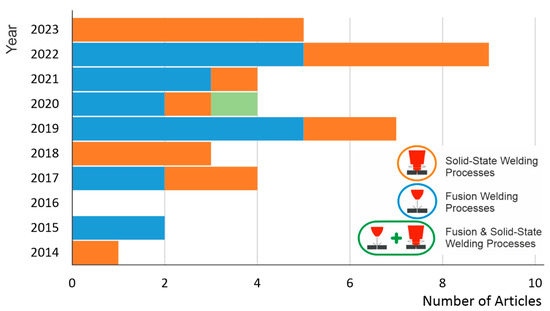
Figure 8.
Yearly evolution of published articles evaluating the weldability of AM Al alloys, for each group of welding processes.
Figure 8 reveals the same number of articles related to the applicability of fusion and solid-state welding processes, confirming the interest from academia and industry for both groups of welding processes.
A summary of the main aspects of the reviewed articles can be found in Table 1. It can be seen that most of the literature works examine the weldability of aluminium produced by the PBF-LB process, while only one also examines parts produced by the WAAM process and compares them with the weldability of the PBF-LB parts.

Table 1.
Overview of available research performed on the evaluation of the weldability of additively manufactured Al alloys [35,36,37,38,39,40,41,42,43,44,45,46,47,48,49,50,51,52,53,54,55,56,57,58,59,60,61,62,63,64,65,66,67,68,69,70,71,72,73].
For a clear understanding of the metallurgical and mechanical consequences of the joining conditions, a division based on the joining process used will be addressed in the discussion of the correlation between the joining process, additive manufacturing technology, and weldability.
5. Fusion Welding Processes
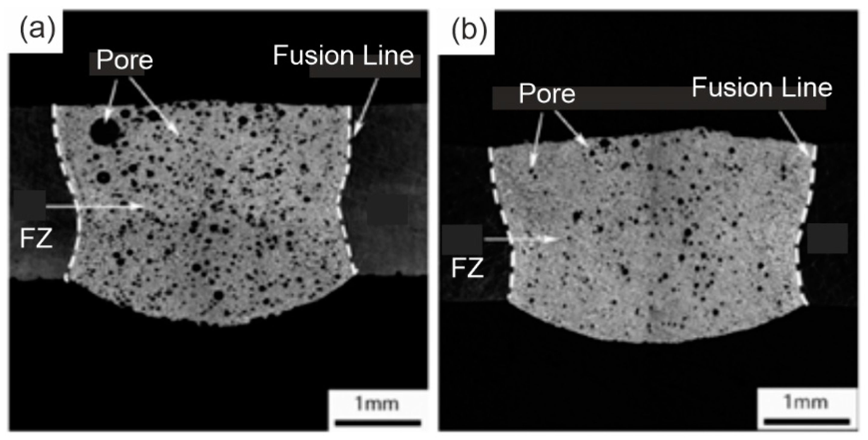
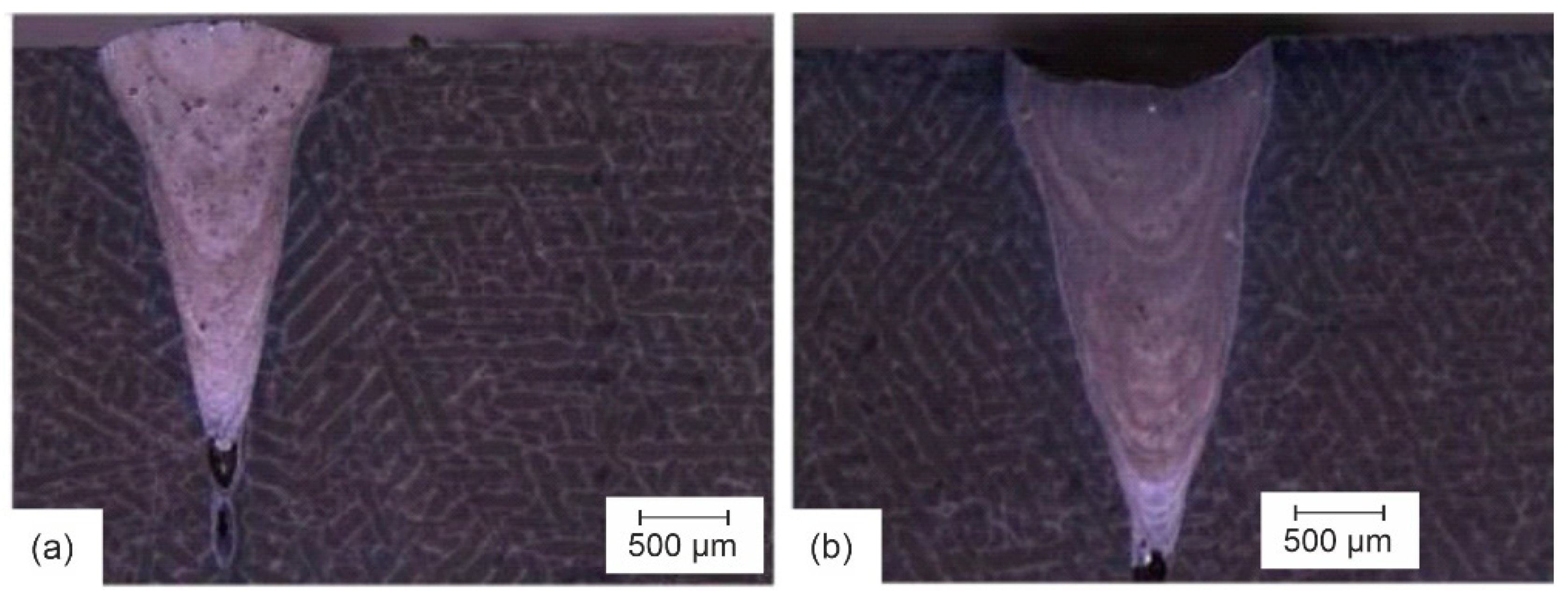
In 2020, Griffiths et al. [35] proposed an evaluation of the GTAW process applied to two components produced by different AM processes. In this case, the weldability of PBF-LB AlSi10Mg and WAAM AlSi12 was evaluated. Figure 9 shows a clear difference in the level of porosity in the welds of the PBF-LB and WAAM parts.
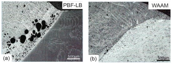
Figure 9.
Cross-sections of welded PBF-LB (a) and WAAM (b) manufactured Al parts, evidencing the formation of a pore belt region in the PBF-LB weld (adapted from [35]).
A critical region is observed in the welds of PBF-LB parts. This pore-rich region is observed in the weld zone (WZ) near the fusion line in the PBF-LB parts. This critical and weak region, which has also been observed by other authors [35,36,37,39,43,44,45,52] and affects the quality of the joint itself, will be referred to as a pore belt for future reference.
Similar results were also found by Zhang et al. [36], who evaluated the difference in weldability of PBF-LB AlSi10Mg alloys using two different fusion welding processes: laser beam welding (LBW) and GTAW processes. The results show a clear difference in porosity location and size distribution in the two welds. The pores in the LBW weld are more homogeneously distributed in the WZ, whereas the pores in the GTAW weld are concentrated in the pore belt region.
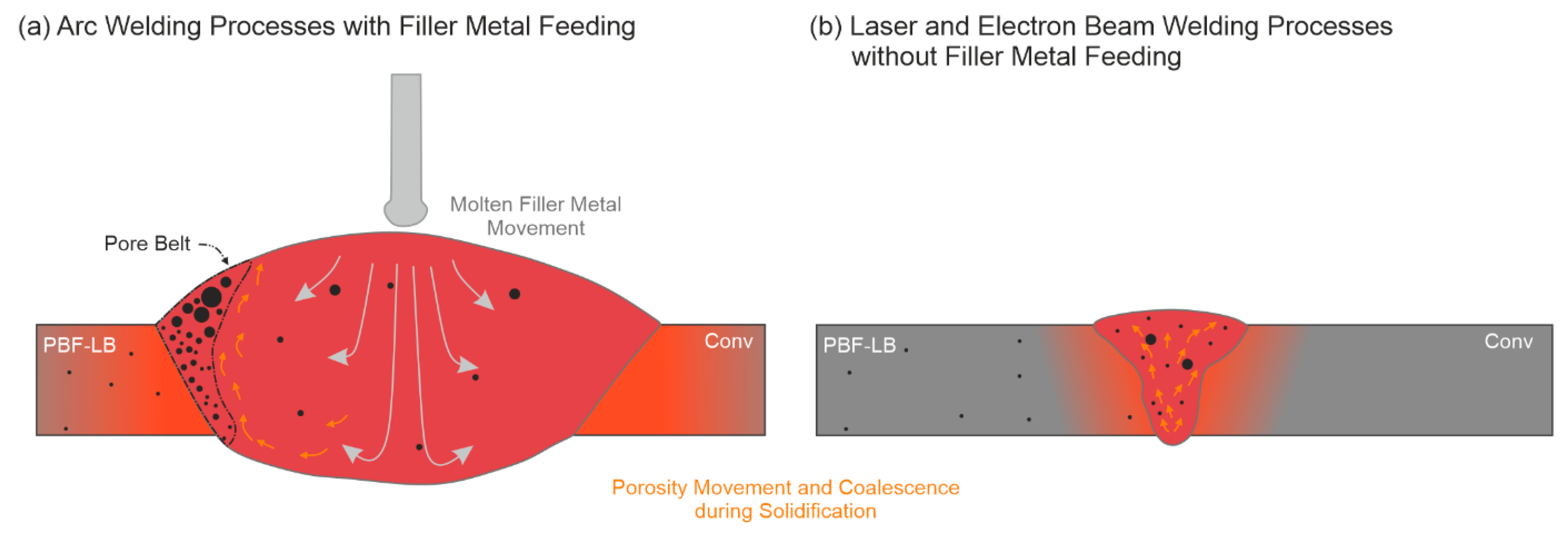
Due to their low energy density compared to LBW, arc welding processes generate a wider molten pool and higher heat dissipation to the surrounding region. Consequently, this results in a longer solidification time, which allows the gas bubbles to rise and coalesce as they move upwards in the molten pool.
In addition to thermal behaviour, most of the work evaluating the LBW process has used the autogenous form of the process, i.e., without the use of filler metal. Even when LBW is used with filler metal, the deposition rates are significantly lower than those possible with arc welding. The filler metal feed acts to push the porosity out, creating a denser region in the centre of the WZ. In other words, it assists in the creation of the pore belt region. This behaviour is also observed in dissimilar welding involving PFB-LB manufactured Al alloy parts [35,36], where the pore belt is formed in the FZ between the WM and the PBF-LB base metal. The described pore movement and coalescence can be observed in Figure 10.

Figure 10.
Mechanism of pore movement and coalescence in the welds of PBF-LB manufactured Al alloy by arc welding (a), and laser and electron beam (b) welding processes.
The LBW process and its particularities will be addressed in the next section.
The central region of the WZ is formed not only by the molten filler metal but also by mixing with both base metals (BM), to an extent that depends on the welding parameters and conditions, as well as the internal forces acting in the melt pool.
Although the formation of pore belts is more evident in arc welding processes, it can also be observed in other fusion welding processes. This topic will be discussed in the following sections.
The results reported in [35] clearly show a significant level of porosity in the welds involving the PBF-LB AlSi10Mg material. Hydrogen measurements showed that the PBF-LB material had a very high hydrogen concentration of 4.3 mL/100 g, compared to a relatively low hydrogen concentration in the WAAM material of 0.5 mL/100 g. Although both values are high compared to typical hydrogen concentrations found in wrought alloys, reported to be 0.05–0.5 mL/100 g [35], the high hydrogen concentration creates an optimized condition for the formation of the pore belt, as shown in Figure 9.
Consistent with the heat input levels of both welding processes, the microstructure in the centre of the weld zone of the LBW weld showed a finer structure than that of the GTAW weld. In the GTAW weld, a large Si-rich eutectic network can be observed (Figure 11a).
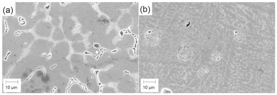
Figure 11.
Typical microstructure of PBF-LB manufactured Al alloy welded by GTAW (a) and LBW (b) welding processes (adapted from [36]).
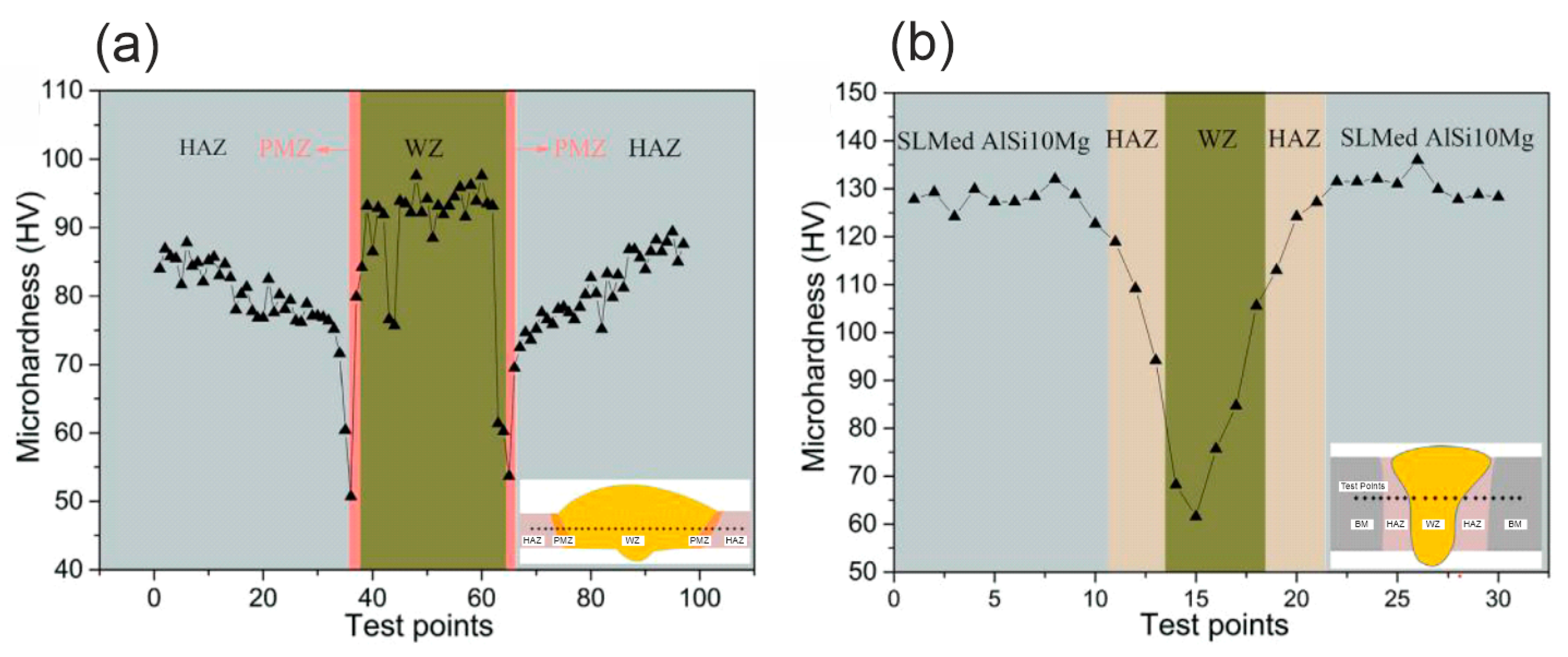
Figure 12 shows the influence of the welding process on the mechanical properties. A higher hardness is found in the WZ of the GTAW weld, whereas in the LBW weld, the hardness in this region is much lower than in the HAZ and BM. This contrast can be attributed to the use of the ER 5183 filler metal during welding. This material contains Mg and Mn which cause the formation of hard solid solution (Mg-Al), precipitates (Mg2Al), and Mn-containing dispersoids. In addition, the Mn-containing dispersoids work in the grain size control and avoid hot cracking during solidification.
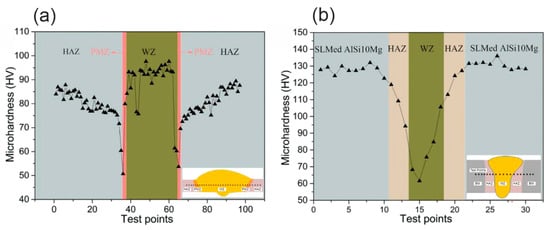
Figure 12.
Microhardness evolution of PBF-LB manufactured Al alloy welded by GTAW (a) and LBW (b) welding processes (adapted from [36]).
The large Si eutectic network size in the GTAW welds resulted in a much lower ultimate tensile strength (UTS) of 120 MPa compared to 210 MPa for the LBW welded specimen. As a result of the GTAW welding process, hardening was observed in WZ. This phenomenon, due to the presence of α-Al cells surrounded by Si-rich eutectic phases, is mainly determined by the PBF-LB AlSi10Mg chemical composition and is common to arc welding processes of this class of materials [12]. This behaviour is similar to what is observed in its cast counterpart, except for the creation of ultrafine eutectic dendrites enclosing the α-Al phase due to the higher cooling rate of the PBF-LB process.
There is also a softening between the fusion line and the PBF-LB BM. This reduction in hardness is due to spheroidization of the Si-rich network within the microstructure [74,75]. This microstructural spheroidization is characterized by an interconnected structure (i.e., network) which breaks down and becomes spherical under the influence of heat. As the influence of the welding heat decreases further away from the WZ, the hardness gradually increases [76].
In their study, Gill et al. [37] compared fusion and solid-state welding processes by evaluating the mechanical properties of the as-built PBF-LB AlSi10Mg BM, GTAW welds, and friction stir welds. As has been shown in detail previously, porosity is highlighted as the major challenge for the GTAW process [35,36]. Although no porosities were found in the FSW welds, softening in the HAZ also reduced the UTS of the joints. The UTS of the as-built BM was equal to 297 MPa; for the GTAW and FSW welds, the UTS was equal to 194 and 200 MPa. The FSW process will be discussed in the following sections.
Several researchers have evaluated the use of the LBW process alone for welding additive-manufactured Al alloys [36,38,39,40,41,42,43,44,45,46,47,48,49,50]. The general and consistent results indicate that porosity is the main defect in these welds [36,38,39,40,41,42,43,44,45,46,47,48,49,50]. According to Emmelmann et al. [38], pores are formed during the welding process of aluminium alloys by a process known as heterogeneous nucleation. This means that pore formation starts from pre-existing surfaces in the melt pool such as refractory phases, nitrides, and oxides. In addition to the high porosity level, Biffi et al. [39] also concluded that LBW of AM Al alloys is feasible, but some challenges such as high energy requirement due to the high reflectivity and the high thermal conductivity still require further research and development. Note that this last aspect is not specific to welding AM parts by LBW but concerns the welding of aluminium in general.
Several authors suggest that the high porosity levels found in welds in PBF-LB are related to its higher hydrogen concentration in the BM, generated by the higher surface area ratio between powder and wire. In addition, the common practice of recycling powder in PBF-LB is altering the laser absorption by the powder and higher oxidation levels during PBF-LB process [77], which will affect the weldability of such materials [40].
In the literature, only one study evaluated the applicability of the LBW welding process to Al plates manufactured by WAAM [41], which will be discussed in the next paragraphs.
Several techniques have been tested with the aim of achieving a lower porosity level and, consequently a higher weld quality and strength. These techniques ranged from parameter optimisation [42], the addition of powder of high quality [40,43], the addition of powder with specific chemical composition variations [44], and pressure environment [45,46,47], to thermal and mechanical post-processing of the PBF-LB material prior to welding [48,49,50].
The optimization of parameters is always an essential method to be used for the improvement of the porosity level for any fusion welding process. Emmelmann et al. [42] evaluated several techniques to increase the melt pool size with the aim of increasing the solidification time, resulting in a longer time for pore movement in the liquid metal. Among the results obtained, the use of a higher welding speed and the multi-mode LBW process showed a lower porosity content [42], especially when using small amplitude values for transversal oscillation of the beam.
By adding powder feeding to the LBW process of PBF-LB AlSi10Mg parts, some authors have observed the positive influence of this technique on the porosity level and mechanical properties [40,43,44]. Through the comparison between autogenous and powder-fed LBW processes, Cui et al. [43] found an increase in the UTS from 169 to 184 MPa. Although there is a significant improvement in UTS compared to autogenous welding, the value shows a dramatic reduction in strength compared to the PBF-LB BM. In a similar way to powder feeding, Pen et al. [44] evaluated the addition of elements Er and Zn to the LBW AlSi10Mg powder, achieving an increase in UTS from 209 to 232 MPa and a reduction in porosity level from 11.8 to 8.1%, see Figure 13. The additions of Er and Zr in the filler metal greatly reduce the size of α-Al cells and Si-rich phases in the WZ. In addition, the additions of the Er and Ze in the filler metal increase the Si precipitates and the dislocation density in the α-Al cells of the WM. Precipitates of Si, Mg2Si, and Al3(Er, Zr) phases were identified within the α-Al cells of the WZ.

Figure 13.
Cross-sections of welded PBF-LB manufactured Al alloys, produced by LBW using filler metal: (a) without Er and Zr addition; (b) with Er and Zr addition [44].
The control of the powder used in the PBF-LB process can help to reduce the porosity of the welds as shown by Beckman et al. [40]. The use of recycled powder in PBF-LB resulted in an increase in the porosity level from 11.0 to 27.0%.
The influence of the pressure environment in laser welding of PBF-LB Al alloys has been investigated in [45,46,47]. By performing laser welding in a vacuum combined with beam oscillation, Schwarz et al. [46] observed a very significant reduction in the porosity from 1.2 to 0.3%. The weld depth was increasing from 1.6 to 2.3 mm. On the contrary, another study concluded that increasing the ambient pressure positively affects the reduction of the porosity level from 10.2 to 2.3% [47], as can be observed in Figure 14. This perspective raises the question regarding the role of laser beam oscillation and low pressure/vacuum.
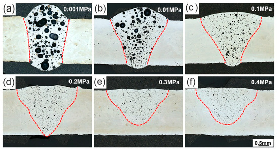
Figure 14.
Cross-section images of welded PBF-LB manufactured Al alloy by LBW process, under ambient pressure of: (a) 0.001 MPa, (b) 0.01 MPa, (c) 0.01 MPa, (d) 0.2 MPa, (e) 0.3 MPa, and (f) 0.4 MPa [47].
Based on a critical analysis of the test results, Möller et al. [50] concluded that no improvement is achieved using inert gas as shielding gas in LBW.
Post PBF-process treatment did not present positive consequences [42,48]. Although the application of heat treatment prior to the welding presented a reduction in the porosity level from 19.0 to 12.5% when pre-heated at 200 °C [40], another study observed a reduction in the UTS from 163 to 144 MPa when welding heat-treated PBF-LB samples [48].
Dimatteo et al. [49] also observed that post-weld heat treatment of PBF-LB sheets has a very significant influence on the mechanical properties of the weld, with the full T6 heat treatment providing the highest mechanical properties. Based on the achieved results, the porosity level in the PBF-LB parts is positively affected by the heat treatment, but the porosities are not completely removed.
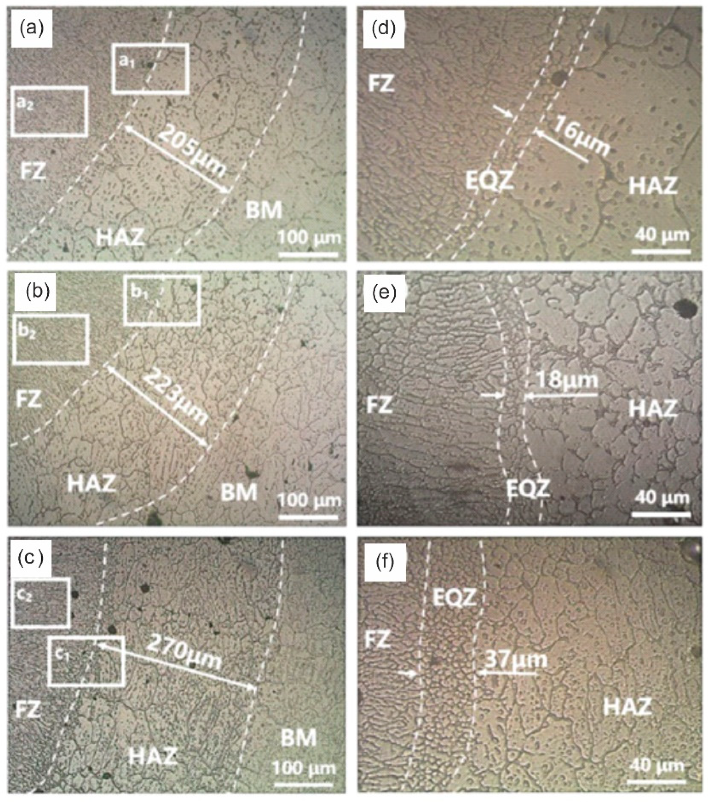
As mentioned before, to the best knowledge of the authors, there is only one study evaluating the weldability of Al parts manufactured by WAAM. In this study, Shi et al. [41] observed the good weldability of WAAM-manufactured 2319 Al alloy, by realising a nearly-free of defects LBW joint. The microstructures of the laser-welded joint consisted of columnar and fine equiaxed grains. However, the heat distribution in both materials during LBW is not uniform. The temperature gradient and grain growth rate are different, so various forms of grain morphologies are generated (Figure 15).
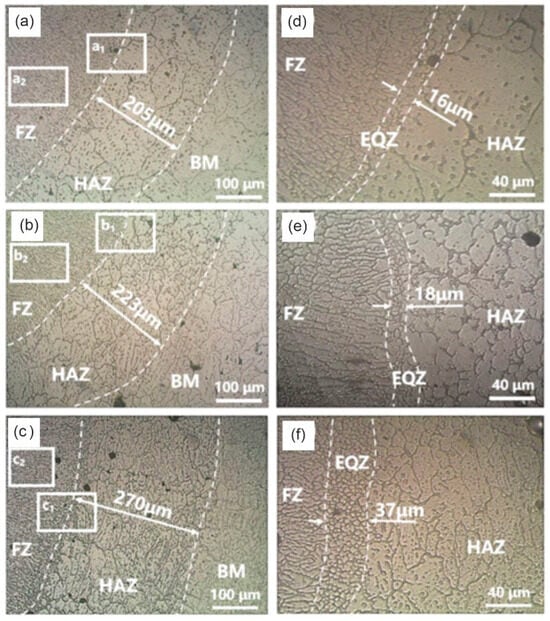
Figure 15.
Microstructure morphology of WAAM 2319 alloy, near the weld fusion line using a laser power of (a,d): 3000 W, (b,e): 3500 W, (c,f): 4000 W. (a–c) microstructure morphology of FZ, HAZ, and BM, (d–f) microstructure morphology of EQZ (adapted from [41]).
The microstructure at the weld edge is shown in Figure 15 from right to left consisting of the BM, HAZ, equiaxed crystal zone (EQZ), and FZ. Notably, the structure and morphology of the HAZ exhibit significant changes compared to the base metal. There is a noticeable occurrence of grain coarsening and an uneven morphology in the microstructure of the HAZ.
In Figure 15d–f, it can be observed that the fusion line serves as a boundary between the HAZ and FZ. Between the HAZ and FZ, there are small crystal bands with a balanced shape. When the molten pool of liquid metal begins to solidify, the process of heterogeneous nucleation becomes more feasible than spontaneous nucleation. This is particularly true for liquid metals with similar chemical compositions and lattice types. Consequently, the area near the fusion line becomes a location where the liquid metal initiates nucleation and grows [41].
As the laser welding speed and the degree of supercooling of the liquid metal increase, the rate of solid phase nucleation near the fusion line also increases. Consequently, the nucleation of liquid metal is encouraged, and the stirring action resulting from the laser oscillation leads to the disruption of larger grains [41]. This, in turn, causes the appearance of fine and compact equiaxed grains in the vicinity of the fusion line region.
In three works from the same team, Nahmany et al. [51,52,53] evaluated the optimisation of the EBW process parameters to reduce the porosity level. Relatively deep and narrow welds were produced and no HAZ was observed. Some pores were found within the WZ, which were attributed to hydrogen blistering. By reducing the welding speed, a wider and deeper weld was achieved, see Figure 16.
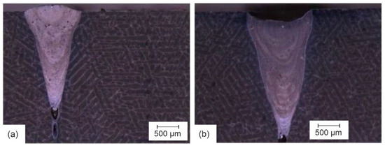
Figure 16.
Macrostructure of EBW welds of PBF-LB manufactured Al alloys using different welding speeds: (a) 1000 mm/min, and (b) 500 mm/min (adapted from [53]).
Similar to what was observed for the laser welding process, the keyhole formation drastically increases the movement of mass and heat within the melt pool, creating a higher probability of porosity formation. The difference in cooling rate at different depths in the weld resulted in different microstructures being present. At the bottom of the WZ (high cooling rate), the eutectic Si-rich network is very thin. It becomes larger at higher positions in the weld, due to the decrease of the cooling rate, see Figure 17. This lower cooling rate gives more time for the eutectic phase to grow [51].
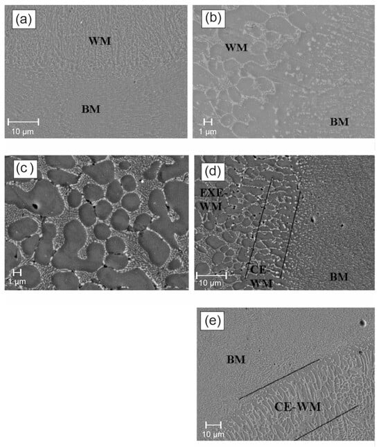
Figure 17.
SEM characterization of an EBW weld of a PBF-LB manufactured Al alloy: (a) weld root; (b) weld material WM/WZ-BM interface, showing a very thin HAZ, with high welding speed: 750 mm/min; (c) typical eutectic microstructure inside the WZ; (d) transition from narrow (∼10 µm) columnar-eutectic (marked as CE-WM) to equiaxed-eutectic (marked as EXE-WM) microstructure, with high welding speed: 750 mm/min; (e) Transition from a wide (~40 µm) columnar-eutectic to an equiaxed-eutectic microstructure, with low welding speed: 240 mm/min [51].
The mechanical tests showed a clear influence of the process parameters and the anisotropy of the BM. Tensile tests showed that the UTS of specimens produced at higher welding speeds was slightly lower than that of specimens produced at lower welding speeds, the reason being the high cooling rate and rapid solidification favouring a fine second-phase structure. The rapid solidification gave less time for the pores in the molten WZ to escape, i.e., they were trapped. It was noted that at high heat input, i.e., at a lower welding speed, the fractures occurred in the BM rather than in the weld, indicating the higher strength of the welded material.
In addition to the need to adjust the welding parameters from conventional cast Al welding to AM Al welding, Michler et al. [54] observed that the electron beam three-spot welding technique achieved a significant porosity reduction in joints made by electron beam welding.
Although the formation of the pore belt region is more pronounced in arc-welded specimens [35,36,37], it has also been observed in LBW-welded specimens [39,43,44,45] and in EBW-welded specimens [52].
Based on the reported ultimate tensile strength values of the welds made by fusion welding processes, the EBW process appears to be the most suitable for welding Al alloys produced by additive PBF-LB (Figure 18). It is not possible to draw any conclusions about the weldability of the Al alloys produced by WAAM, since there is only one work evaluating this class of materials without reporting tensile test results.
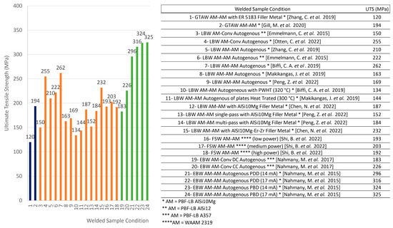
Figure 18.
Ultimate tensile strength of PBF-LB manufactured Al alloys welded by fusion welding processes: GTAW, LBW, and EBW processes. All AM samples are manufactured with PBF-LB AlSi10Mg powder, except samples 3 and 6 which are manufactured with PBF-LB AlSi12 powder, and samples 16 and 17 which were manufactured with PBF-LB A357 powder. (Data analysis from [36,37,38,39,41,44,45,47,48,51,52]).
6. Solid State Welding Processes
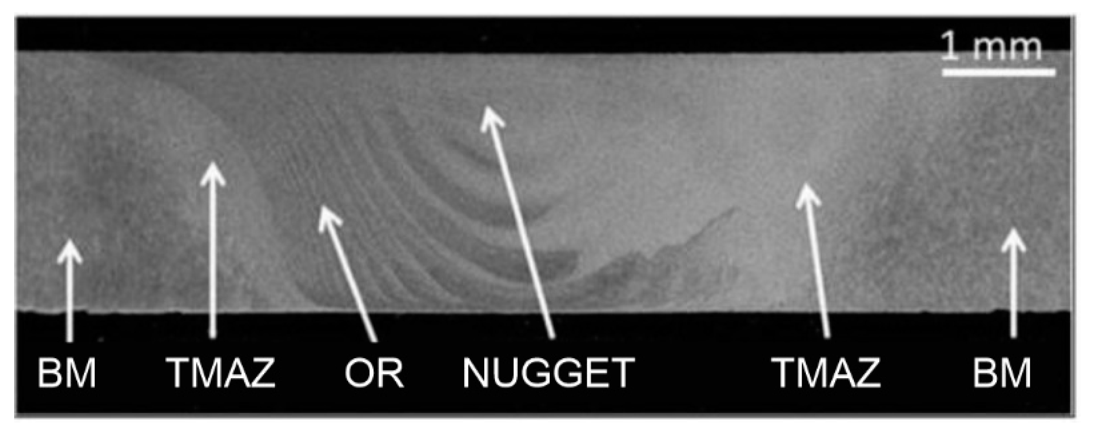
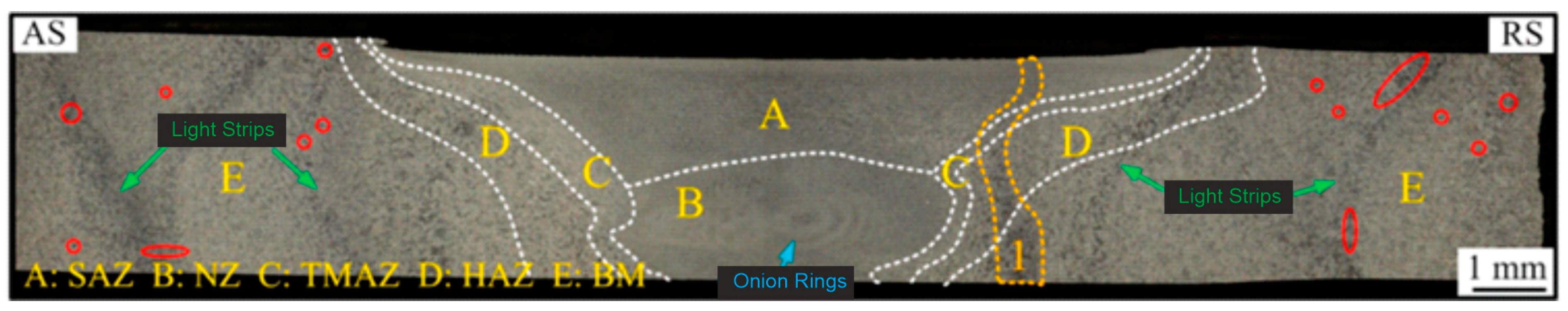
Of all the solid-state welding processes evaluated, FSW is by far the most widely used process for joining AM-manufactured Al alloys [37,55,56,57,58,59,60,61,62,63,64,65,66,67,68,69,70]. For this process, only studies were found evaluating the weldability of parts produced by the PBF-LB process. The typical microstructure of the final product can be divided into 4 different zones: the base or parent material (BM), the thermo-mechanically affected zones (TMAZ), the onion rings (OR), and the weld nugget (WN), see Figure 19. Most of the available work has observed the formation of a softened region in the weld nugget and the thermo-mechanically affected zone. As a first clear difference to the welds produced by fusion welding processes, the FSW welds of PBF-LB Al alloys show virtually no porosity.

Figure 19.
Macrograph of a typical FSW weld of a PBF-LB manufactured Al alloy, highlighting the different zones (adapted from [56]).
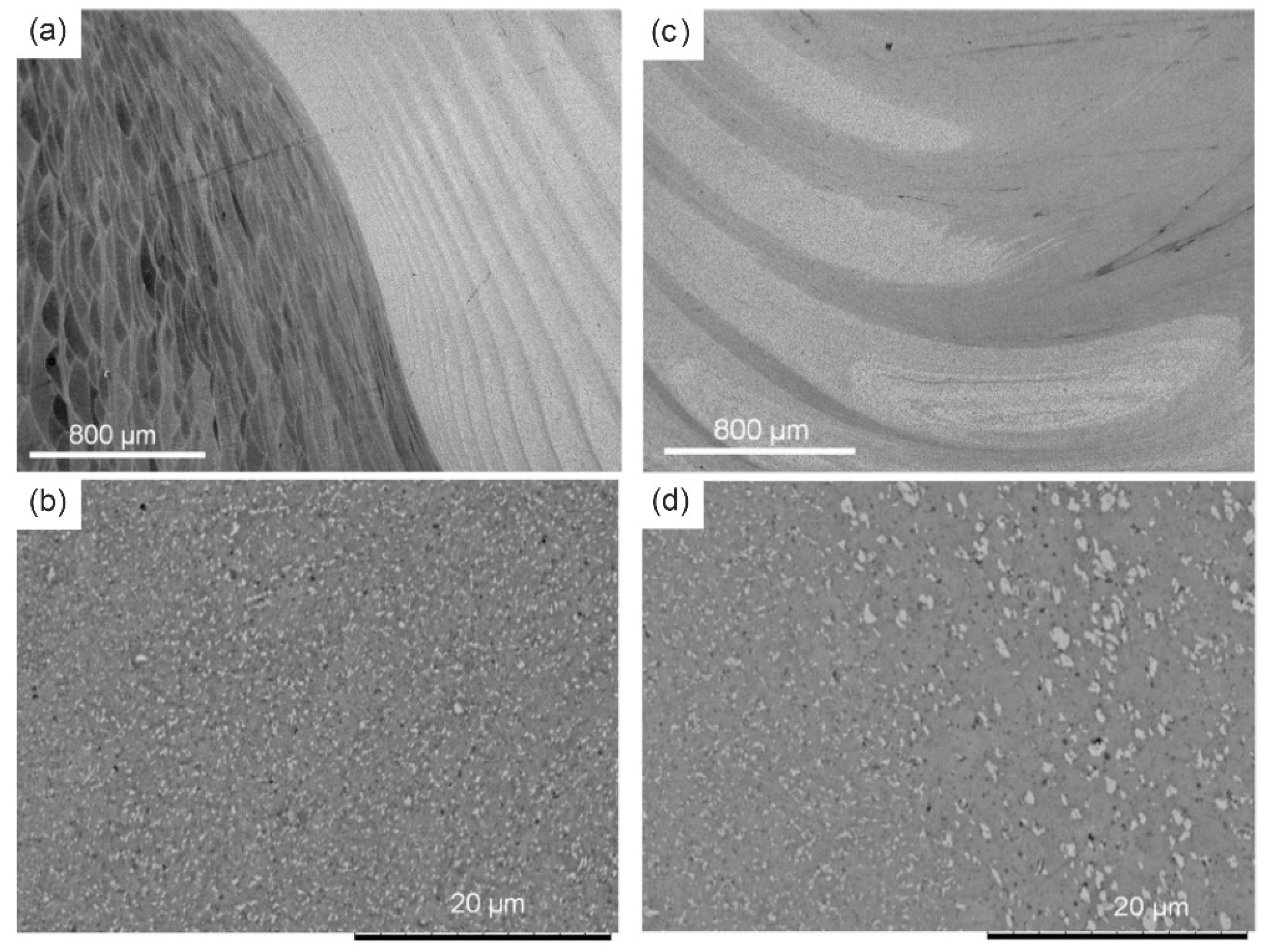
As can be seen in Figure 20, the weld nugget is characterised by the highly deformed structure of the TMAZ, located between the base material and the nugget zone (Figure 20a). The TMAZ exhibits distinct features when subjected to elevated temperatures and deformation. It displays a significantly deformed structure, with grains elongated in an upward-flowing pattern, compressed around the nugget zone due to the tool’s forging action. In this region, recrystallization and grain coarsening are absent, likely because of insufficient deformation strain.

Figure 20.
Micrograph of different zones in the FSW weld of a PBF-LB manufactured Al alloy: (a) boundary between the TMAZ and the OR, (b) TMAZ, (c) nugget zone, and (d) boundary between TMAZ and nugget zone (adapted from [56]).
Figure 20c illustrates the morphology of the nugget zone. The nugget zone is made of fine grains resulting from the significant plastic deformation, frictional heating, and subsequent dynamic recrystallization processes that the material undergoes during FSW [48,50]. Figure 20c shows the distinct onion ring structures are visible, with a more pronounced presence on the advancing side. This heightened presence is attributed to the expectedly greater plastic deformation on the advancing side during the welding process [56].
The influence of the addition of 2 wt% nAl2O3 to the AlSi10Mg during the PBF-LB manufacturing process was evaluated by two studies [58,59]. The obtained results show an increase in the porosity level from 0.07 to 0.10% at low heat input and from 0.06 to 0.16% at high heat input [58]. The microhardness was also affected by the change in the chemical composition of the powder and showed an increase from 68 to 75 HV at low heat input and from 67 to 74 HV at high heat input [58]. Manipulation of the chemical composition had a negative effect on the mechanical strength of the welds, resulting in a decrease of the UTS from 238 to 146 MPa at low heat input and from 240 to 135 MPa at high heat input [58].
In terms of parameter optimisation, some studies evaluated the influence of the heat input on the microstructure and mechanical properties, by varying welding speed, downforce, tool rotational speed, tool transversal speed, and tool tilt angle. From one perspective, two studies concluded that a higher heat input has a positive effect on the weldability of those materials. Du et al. [60] also reported that by using a higher heat input, the UTS increased from 132 MPa at a low heat input to 236 MPa at a high heat input and to 240 MPa at an even higher heat input. In their work, the authors varied the heat input by changing the welding speed (3 mm/s—low heat input, 1 mm/s—high and higher heat input) and the downforce (3.75 kN—low heat input, 1.57 kN—high heat input, 4.00 kN—higher heat input). In terms of process parameters optimization, Minhas et al. [61] performed an extensive set of experiments, finding that the joint quality is significantly influenced by the tool rotational speed with a contribution of 48.2%, followed by the tool tilt angle, and the tool transverse speed. The highest UTS (234 MPa) was achieved by using a tool rotational speed of 984 RPM, and a transversal speed of 63 mm/min. This behaviour can be explained by the increased heat input associated with the higher rotational speed. From a surface quality point of view, Thakur et al. [62] pointed out another consequence of using high heat input in the FSW process. By increasing the rotational speed, the surface texture of the weld bead is significantly changed, from a highly rough surface with tool marks and embedded plastically deformed chips, to a nearly smooth surface.
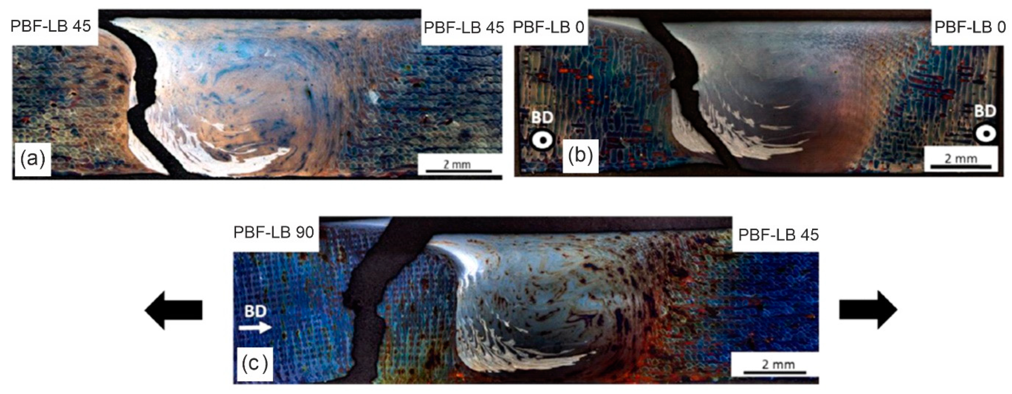
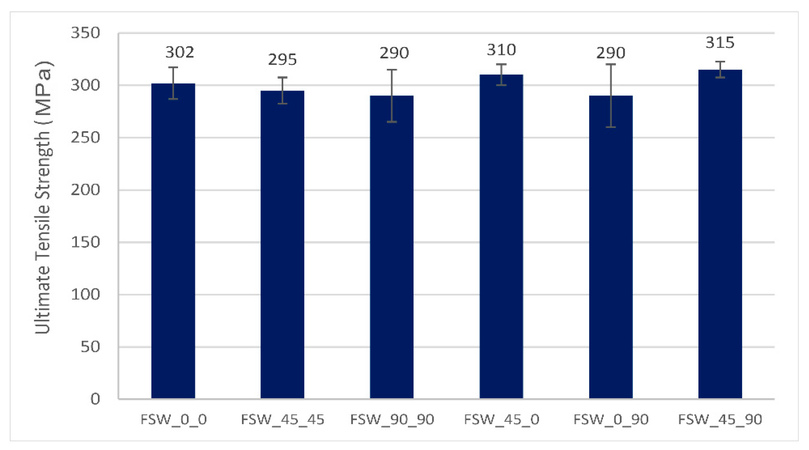
As with any AM process, the printing/built direction affects the microstructural evolution, the mechanical properties, and consequently the weldability of the material. Moeini et al. [63] evaluated the influence of the build-up direction on the weldability for FSW, see Figure 21. A slight difference in UTS is observed, with values ranging from about 295 MPa (FSW_90_90 sample) to 315 MPa (FSW_45_90 sample, shown in Figure 21c), see Figure 22. The label of samples is related to the build orientation of the welded samples, see Figure 23.

Figure 21.
Failure path following tensile testing, highlighted on the cross-section of FSW weld of PBF-LB manufactured AlSi10Mg alloys in different build directions: between sheets manufactured with similar build directions 45° and 45° (a), and 0° and 0° (b), and with dissimilar build directions 90° and 45° (c) (adapted from [63]).

Figure 22.
Ultimate tensile strength of PBF-LB manufactured AlSi10Mg parts welded by FSW process in different build directions (adapted from [63]).
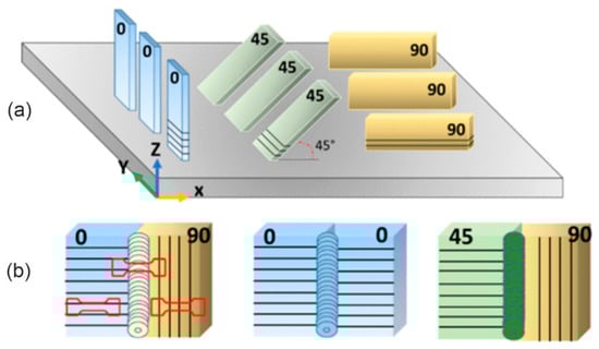
Figure 23.
(a) Schematic illustration of the AM samples processed by PBF-LB at different build orientations, and (b) exemplary samples with similar and dissimilar build orientations joint by FSW (adapted from [63]).
As with fusion welding processes, the vast majority of studies assessing the weldability of Al parts fabricated with PBF-LB compared to other AM (e.g., WAAM) manufactured samples. By performing FSW on 205A (high-strength cast aluminium alloy) samples manufactured by WAAM, Zhou et al. [70] achieved a satisfactory weld quality, detecting no welding defects. The pores, originally found in the WAAM samples, were almost eliminated in the FSW joint due to the locally severe plastic deformation. The pores in the WAAM BM are highlighted in red in Figure 24.

Figure 24.
Macrography of FSW joint for the WAAM 205A fabricated sample [64].
In each region of the FSW joint, different degrees of recrystallization occurred, where the highest degree of recrystallization was found in the SZ. The FSW joint not only maintained a high strength but also had improved ductility compared to the WAAM 205A base material. The UTS, YS, and elongation at fracture of the FSW joint were 224 MPa, 116 MPa, and 9%, respectively [70].
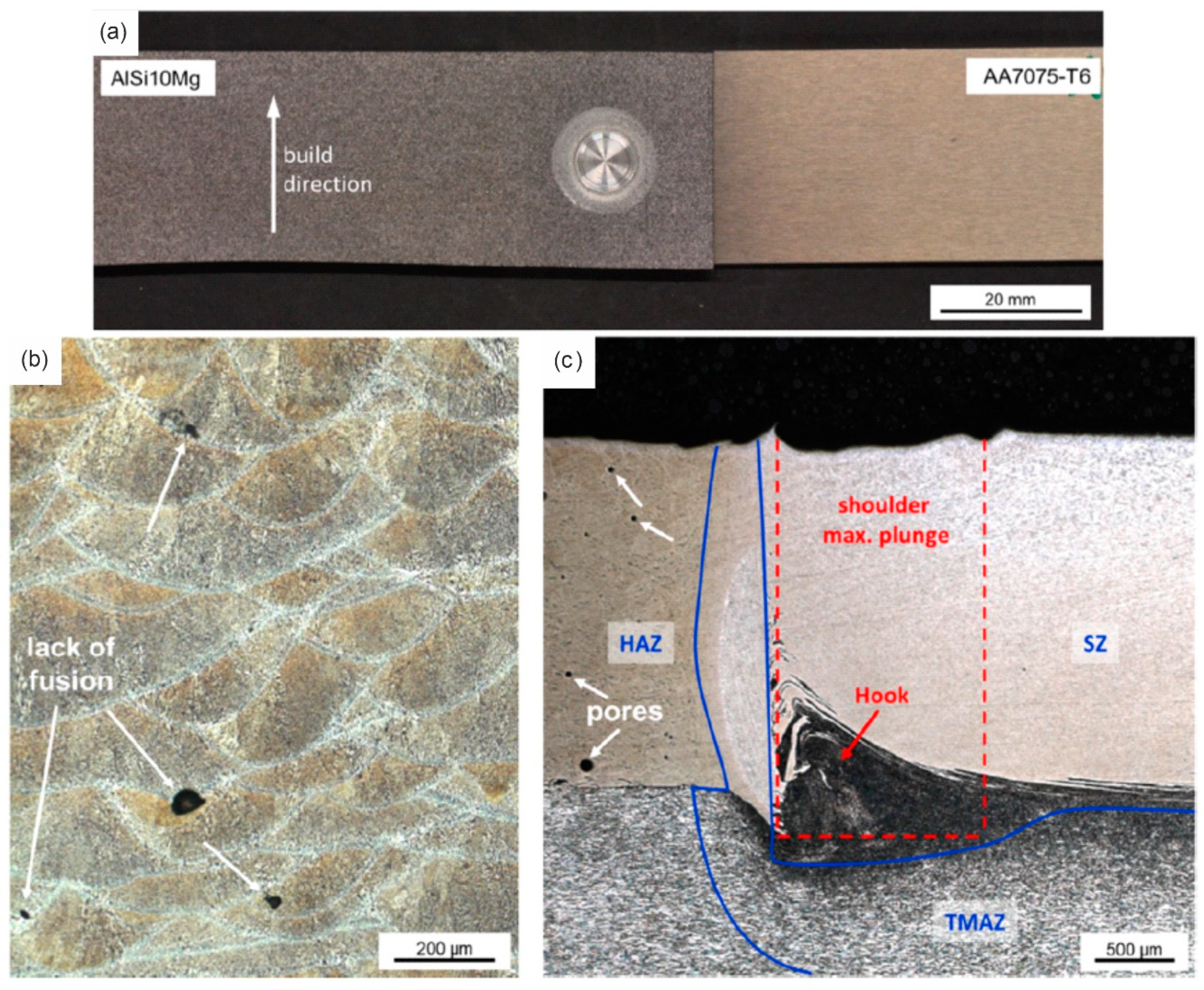
To the best knowledge of the authors, there is only one study evaluating the use of the RFSSW process for welding AM Al parts. In this study, Fritsche et al. [71] joined AlSi10Mg Al alloy produced by PBF-LB to wrought AA7075-T6. Although no joint defects were observed by metallographic examination (Figure 25), a significant softening effect was observed in the SZ and TMAZ zones. The highest Ultimate Lap Shear Force (ULSF) was found to be 9.16 kN.
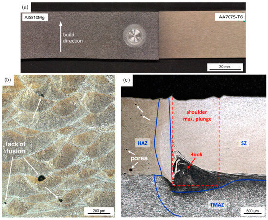
Figure 25.
RFSSW weld of PBF-LB manufactured AlSi10Mg: (a) top view of the weld, (b) microstructure of AlSi10Mg in as-built condition, and (c) the hook region [71].
The RFW joining of PBF-LB AlSi12 has been evaluated by Prashanth et al. [72]. A very significant softening in the WZ was evidenced. This observed phenomenon is due to the reduction of the Si content in Al in the WZ to about 1.5 wt%, with a relatively coarse grain size of Al and Si (190 nm and 90 nm, respectively). In addition, the morphology of Si changes from a continuous submicron Si network for the PBF-LB BM to micron-sized homogeneously distributed Si particles in the WZ. A UTS value of approximately 310 MPa was achieved in the evaluated welding condition.
Prashanth et al. observed the segregation of Si in certain areas of the RFW weld, particularly in the globular Si-rich phase [72]. Similar observations were made by Scherillo et al. in an FSW weld of PBF-LB-produced AlSi10Mg [56]. However, the weight fraction of the globular Si-rich phase differed significantly between the two welding processes, with 9% in the FSW weld [56] and 10.5% in the RFW weld [72].
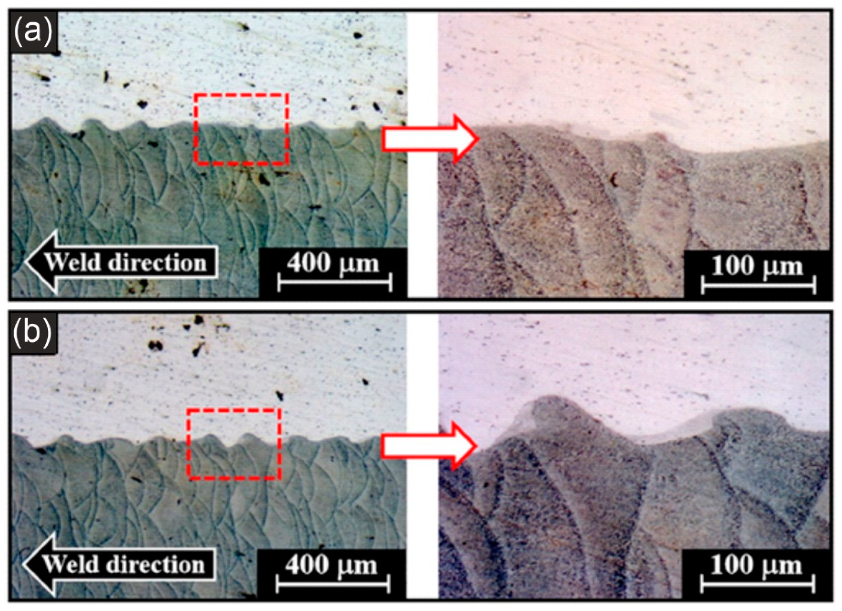
In what concerns Magnetic Pulse Welding (MPW) of AM parts, Shribman et al. [73] performed MPW of PBF-LB manufactured AlSi10Mg to wrought AA6060-T6 alloys. The MPW process resulted in relatively minor metallurgical modification in the workpieces, see Figure 26. Based on the microhardness profile evaluation, minor hardening in the regions adjacent to the joint was observed, which is typical for the MPW process and is expectedly due to the local severe plastic deformation.

Figure 26.
Macrography in the beginning region (a) and the centre region (b) of the MPW joint of PBF-LB AlSi10Mg fabricated sample. The last one (b) shows the formation of “regular” waves, slightly larger “peak-to-peak” than the beginning region of the weld seam.(adapted from [73]).
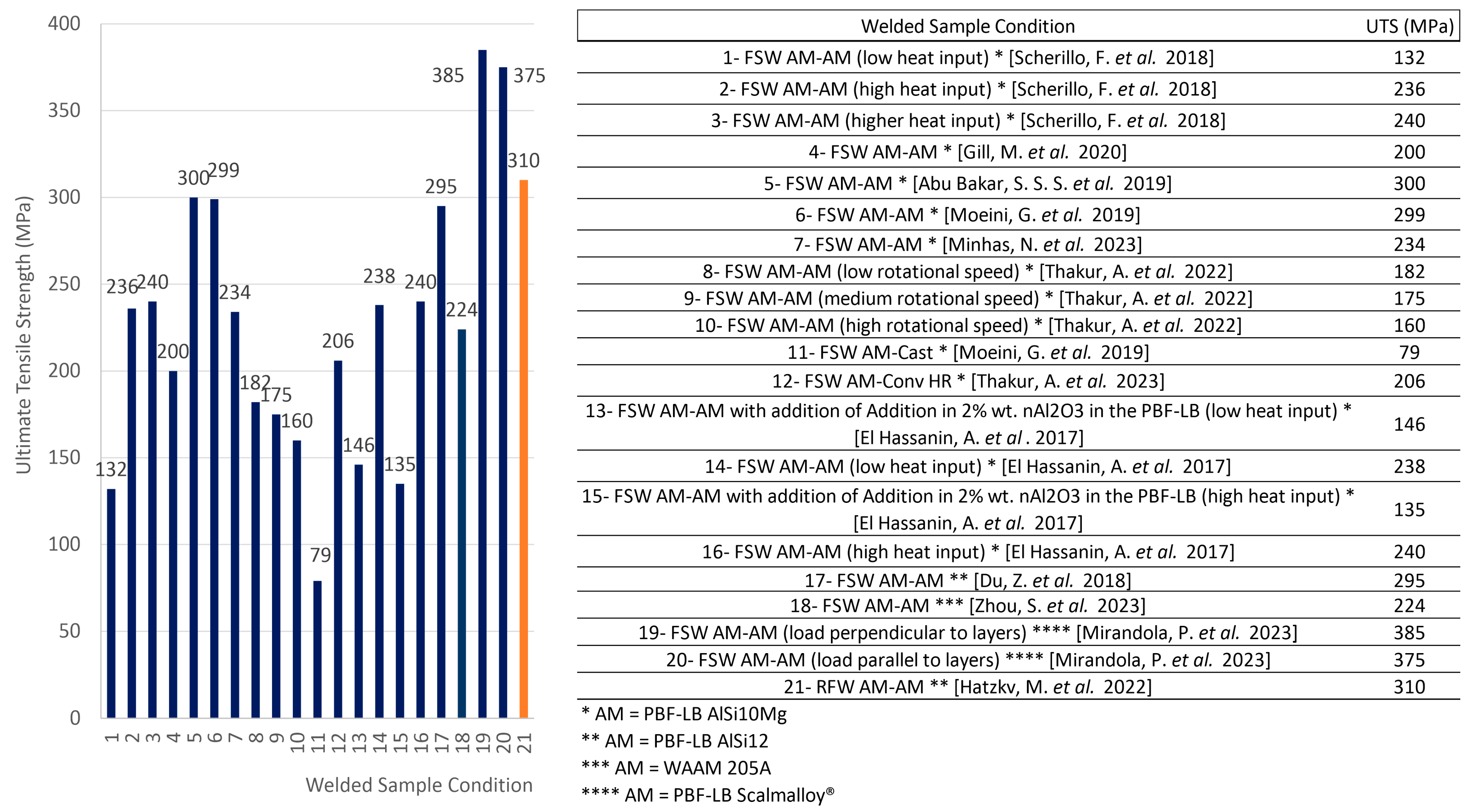
The reported ultimate tensile strength values of the welds performed using solid-state welding processes show a very similar average value compared to the values obtained by fusion welding processes (Figure 18). In addition, the high standard deviation is also highlighted by the discrepancy in the results Figure 27. The obtained UTS average and standard deviation were equal to 212 and 62 MPa for fusion welding processes, and 219 and 73 MPa for solid-state welding processes. The high standard deviation confirms the expected influence of the AM manufacturing process on the weldability.
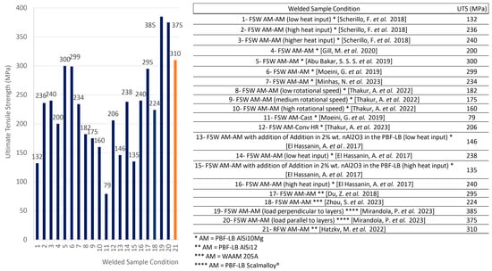
Figure 27.
Ultimate tensile strength of PBF-LB manufactured Al alloys welded by solid-state welding processes: FSW, and RFW processes. All AM samples are manufactured with PBF-LB AlSi10Mg powder, except samples 12 and 13, which are manufactured with PBF-LB AlSi12 (data analysis from [37,56,57,59,60,61,62,65,66,68,69,70]).
7. Final Considerations and Future Prospects
Even when considering the same (or very similar) chemical composition, the AM processes of aluminium parts influence the complexity of welding, in terms of repeatability, the window of parameters, and achievable weld quality. As different AM processes produce different microstructures and mechanical properties, the weldability of these materials is also different.
A common feature described by all authors who studied the fusion welding of aluminium parts produced by PBF-LB is the significantly higher pore susceptibility compared to conventional materials of the same alloy. A significantly high porosity content after fusion welding has been found for the two typical aluminium alloys used in PBF-LB, i.e., AlSi10Mg [35,36,37,39,42,43,44,45,46,47,48,49,50,51,52,53] and AlSi12 [35,38,40], especially in the WZ region near the PBF-LB BM, the so-called pore belt region.
However, differences in the mechanism of hydrogen pore formation have been reported. For example, the reason for the high porosity content of the welds was largely attributed to the inherent small pores present in the PBF-LB BM as a result of the floating and growth or coalescence of the tiny pores in the weld pool. However, several other studies found that the main reason for the high porosity content was not the presence of hydrogen in the microvoids, but a much higher amount of oxygen and hydrogen in the PBF-LB compared to WAAM Al alloy parts [35]. Beckmann et al. [40] reported that the hydrogen content in the AM components was seven times higher than in cast materials. Prashanth et al. [72] have proposed that the pre-existing oxide films may be the cause of pore formation in the WZ of the PBF-LB Al-Si alloys, as the dissolved hydrogen coming from the oxide films covering the powder or from moisture may recombine, resulting in spherical porosity. These observations indicate that the mechanism of increased pore formation in the welded joints of PBF-LB AlSi10Mg alloys is not yet well understood.
It is also suggested that the high porosity content is due to the raw material used in the PBF-LB process. Due to the drastically higher surface area to volume ratio of the powder compared to wire, the powder feedstock adsorbs a large amount of water vapour. It is also believed that most of the hydrogen is retained in solution in the PBF-LB material as a result of the faster cooling rates associated with the PBF-LB process, compared to conventional fusion welding used in the WAAM process. In this way, the reduced surface area to volume ratio of the wire consumables and the lower cooling rates during the WAAM process could combine to reduce the hydrogen concentration in the WAAM material and consequently in the welds.
In addition to that, the high standard deviation of mechanical values achieved in all presented studies, including fusion and solid-state welding processes, shows a clear correlation with the quality of the AM-manufactured Al part. The practice of powder recycling in the PBF-LB process, for example, is well-known as best practice varying from company to company. Based on that, in order to obtain optimized parameters for joining additively manufactured Al parts, a higher control of the manufacturing of the base materials is also necessary.
In parallel with the high complexity of the process, there is an apparent lack of information on specific aspects of the weldability of AM Al alloys. Since most of the available articles address a feasibility investigation, a lack of quantitative results is also present.
Indeed, future work should address this issue in a more complete and in-depth manner, evaluating the influence of the quality of the filler material, the shielding gas, the control of the heat input, and the different methods of cleaning the sheets before welding, using different fusion and solid state welding processes (GMAW, GTAW, LBW, PAW, FSW and RFW), in order to obtain a complete overview of the weldability of aluminium alloys produced by PBF-LB and WAAM processes.
Author Contributions
Conceptualization: R.N., K.F., W.V., W.D.W., A.S., M.L., W.S. and J.A.; Investigation: R.N.; Analysis of research: R.N., K.F., W.V., W.D.W., A.S., M.L., W.S. and J.A.; Writing—original draft preparation: R.N.; Review and editing: R.N., K.F., W.V., W.D.W., A.S., M.L. and J.A. All authors have read and agreed to the published version of the manuscript.
Funding
The presented comparison and discussions on the weldability of additively manufactured aluminium alloys were achieved during the COAMWELD project: “Advanced metal components through optimal combination of additive manufacturing and welding techniques”, funded by VLAIO (Flanders Innovation & Entrepreneurship) under Grant Agreement HBC.2020.2994.
Data Availability Statement
Data sharing not applicable. No new data were created or analyzed in this study. Data sharing is not applicable to this article.
Conflicts of Interest
The authors declare no conflict of interest.
Abbreviations
| Al | Aluminium |
| AM | Additive Manufacturing |
| BM | Base Material |
| DED | Directed Energy Deposition |
| DED-Arc | Directed Energy Deposition by Arc |
| DMLM | Direct Metal Laser Melting |
| DMLS | Direct Metal Laser Sintering |
| EBW | Electron Beam Welding |
| EQZ | Equiaxed Crystal Zone |
| FL | Fusion Line |
| FSW | Friction Stir Welding |
| FZ | Fusion Zone |
| GMAW | Gas Metal Arc Welding |
| GTAW | Gas Tungsten Arc Welding |
| HAZ | Heat Affected Zone |
| LBW | Laser Beam Welding |
| MPW | Magnetic Pulse Welding |
| OR | Onion Ring |
| PAW | Plasma Arc Welding |
| PBF | Powder Bed Fusion |
| PBF-EB | Powder Bed Fusion by Electron Beam |
| PBF-LB | Powder Bed Fusion by Laser Beam |
| PMZ | Partial Melting Zone |
| RFSSW | Refill Friction Stir Spot Welding |
| RFW | Rotational Friction Welding |
| SAW | Submerged Arc Welding |
| SEM | Scanning Electron Microscope |
| SLM | Selective Laser Melting |
| TMAZ | Thermo-Mechanically Zone |
| UTS | Ultimate Tensile Strength |
| WAAM | Wire Arc Additive Manufacturing |
| WN | Weld Nugget |
| WZ | Weld Zone |
References
- Nunes, R.; Vandermeiren, N.; Verlinde, W.; Boruah, D.; Motte, R.; De Waele, W. A Benchmark of Mechanical Properties and Operational Parameters of Different Steel Filler Metals for Wire Arc Additive Manufacturing. Int. J. Adv. Manuf. Technol. 2023, 127, 599–613. [Google Scholar] [CrossRef]
- Vafadar, A.; Guzzomi, F.; Rassau, A.; Hayward, K. Advances in Metal Additive Manufacturing: A Review of Common Processes, Industrial Applications, and Current Challenges. Appl. Sci. 2021, 11, 1213. [Google Scholar] [CrossRef]
- Rasiya, G.; Shukla, A.; Saran, k. Additive Manufacturing—A Review. Mater. Today Proc. 2021, 47, 6896–6901. [Google Scholar] [CrossRef]
- ASTM ISO Standard Terminology for Additive Manufacturing: General Principles—Fundamental and Vocabulary, Astm.Org. 2022. Available online: https://www.astm.org/Standards/ISOASTM52900.htm (accessed on 10 July 2023).
- Gao, B.; Zhao, H.; Peng, L.; Sun, Z. A Review of Research Progress in Selective Laser Melting (SLM). Micromachines 2023, 14, 57. [Google Scholar] [CrossRef] [PubMed]
- Ashwath, P.; Anthony Xavior, M.; Jeyapandiarajan, P.; Joel, J.; Batako, A. Surface Finish and Property Evaluation of Direct Metal Laser Sintered (DMLS) Al-Si-10Mg alloy. J. Phys. Conf. Ser. 2022, 2198, 012055. [Google Scholar] [CrossRef]
- Çelik, A.; Tekoğlu, E.; Yasa, E.; Sönmez, M.Ş. Contact-Free Support Structures for the Direct Metal Laser Melting Process. Materials 2022, 15, 3765. [Google Scholar] [CrossRef]
- Shah, A.; Aliyev, R.; Zeidler, H.; Krinke, S. A Review of the Recent Developments and Challenges in Wire Arc Additive Manufacturing (WAAM) Process. J. Manuf. Mater. Process. 2023, 7, 97. [Google Scholar] [CrossRef]
- Gradl, P.; Tinker, D.C.; Park, A.; Mireles, O.R.; Garcia, M.; Wilkerson, R.; Mckinney, C. Robust Metal Additive Manufacturing Process Selection and Development for Aerospace Components. J. Mater. Eng. Perform. 2022, 31, 6013–6044. [Google Scholar] [CrossRef]
- Elementum 3D—An Inside Look at How AM Aluminium Alloys Are Possible Using RAM Technology. Available online: https://www.elementum3d.com/white-papers/an-inside-look-at-how-am-commercial-aluminum-alloys-are-made-possible-using-ram-technology/ (accessed on 5 June 2023).
- Migal–Wire Arc Additive Manufacturing (WAAM). Available online: https://www.migal.co/produkte/waam (accessed on 5 June 2023).
- Zhao, L.; Song, L.; Macias, J.G.S.; Zhu, Y.; Huang, M.; Simar, A.; Li, Z. Review on the correlation between microstructure and mechanical performance for laser powder bed fusion AlSi10Mg. Addit. Manuf. 2022, 56, 102914. [Google Scholar] [CrossRef]
- Macias, J.G.S.; Elangeswaran, C.; Zhao, L.; Buffiere, J.Y.; Hooreweder, B.V.; Simar, A. Fatigue crack nucleation and growth in laser powder bed fusion AlSi10Mg under as built and post-treated conditions. Mater. Des. 2021, 210, 110084. [Google Scholar] [CrossRef]
- DebRoy, T.; Mukherjee, T.; Wei, H.L.; Elmer, J.W.; Milewski, J.O. Metallurgy, mechanistic models and machine learning in metal printing. Nat. Rev. Mater. 2020, 6, 48–68. [Google Scholar] [CrossRef]
- Macias, J.G.S.; Douillard, T.; Zhao, L.; Maire, V.; Pyka, G.; Simar, A. Influence on microstructure, strength and ductility of build platform temperature during laser powder bed fusion of AlSi10Mg. Acta Mater. 2020, 201, 231–243. [Google Scholar] [CrossRef]
- Wang, J.; Zhu, K.; Zhang, W.; Zhu, X.; Lu, X. Microstructural and defect evolution during WAAM resulting in mechanical property differences for AA5356 component. J. Mater. Res. Technol. 2023, 22, 982–996. [Google Scholar] [CrossRef]
- Verma, R.P.; Pandey, K.N.; Andras, K.; Khargotra, R.; Singh, T. Difficulties and redressal in joining of aluminium alloys by GMA and GTA welding: A review. J. Mater. Res. Technol. 2023, 23, 2576–2586. [Google Scholar] [CrossRef]
- Rao, G.A.; Kumar, B.R.; Kumar, G.N.; Mahender, N.; Kumar, T.U. Study the effect process of parameters on friction welding of dissimilar metals AISI 304 steel and AA 2219 aluminium. AIP Conf. Proc. 2021, 2317, 030013. [Google Scholar] [CrossRef]
- Belyaev, S.; Vladimir, N.B.; Ivan, Y.G.; Boris, P.K.; Elena, M.L.; Bezrukikh, A.; Victor, V.L.; Vladimir, I.K.; Koptseva, N. Saturation dynamics of aluminum alloys with hydrogen. ARPN J. Eng. Appl. Sci. 2017, 12, 6243–6247. [Google Scholar]
- Silva, C.L.M.; Scotti, A. The influence of double pulse on porosity formation in aluminum GMAW. J. Mater. Process. Technol. 2006, 171, 366–372. [Google Scholar] [CrossRef]
- Cordova, L.; Bor, T.; Campos, M.; Tinga, T. Drying Strategies to Reduce the Formation of Hydrogen Porosity in Al Alloys Produced by Additive Manufacturing. II Congresso Iberoamericano de Pulvimetalurgia CEIPM. 2019. Available online: https://easychair.org/publications/preprint/V1ld (accessed on 10 July 2023).
- Olabode, M.; Kah, P.; Hiltunen, E.; Martikainen, J. Effect of Al2O3 film on the mechanical properties of a welded high-strength (AW 7020) aluminium alloy. Proc. Inst. Mech. Eng. Part B J. Eng. Manuf. 2015, 230, 2092–2101. [Google Scholar] [CrossRef]
- Lawal, L.S.; Afolalu, A.S.; Jen, T.C.; Akinlabi, E.T. Tungsten inert gas (TIG) and metal inert gas (MIG) welding applications -critical review. In Proceedings of the VIII International Conference on Advanced Agritechnologies, Environmental Engineering and Sustainable Development–AGRITECH, Krasnoyarsk, Russia, 29–31 March 2023. [Google Scholar] [CrossRef]
- Zhan, X.; Zhao, W.; Liu, Z.; Gao, Q.; Bu, H. Microstructure and porosity characteristics of 5A06 aluminum alloy joints using Laser-MIG hybrid welding. J. Manuf. Process. 2018, 35, 437–445. [Google Scholar] [CrossRef]
- Zhang, C.; Gao, M.; Zeng, X. Effect of microstructural characteristics on high cycle fatigue properties of Laser-arc hybrid welded AA6082 aluminum alloy. J. Am. Acad. Dermatol. 2016, 231, 479–487. [Google Scholar] [CrossRef]
- Ardika, R.D.; Triyono, T.; Muhayat, M. A Review Porosity in Aluminum Welding. In Proceedings of the IGF26–26th International Conference on Fracture and Structural Integrity, Turin, Italy, 26–31 May 2021. [Google Scholar] [CrossRef]
- Cong, B.; Ding, J.; Williams, S. Effect of arc mode in cold metal transfer process on porosity of additively manufactured Al-6.3% Cu alloy. Int. J. Adv. Manuf. Technol. 2015, 76, 1593–1606. [Google Scholar] [CrossRef]
- Yu, J.; Kim, D. Effects of welding current and torch position parameters on minimizing the weld porosity of zinc-coated steel. Int. J. Adv. Manuf. Technol. 2018, 95, 551–567. [Google Scholar] [CrossRef]
- Liu, W.; Wang, H.; Lu, F.; Cui, H.; Tang, X. Investigation on effects of process parameters on porosity in dissimilar Al alloy lap fillet welds. Int. J. Adv. Manuf. Technol. 2015, 81, 843–849. [Google Scholar] [CrossRef]
- Li, K.; Lu, F.; Cui, H.; Li, X.; Tang, X.; Li, Z. Investigation on the effects of shielding gas on porosity in fiber Laser welding of T-joint steels. Int. J. Adv. Manuf. Technol. 2014, 77, 1881–1888. [Google Scholar] [CrossRef]
- Katayama, S.; Naito, Y.; Uchiumi, S.; Mizutani, M. Physical phenomena and porosity prevention mechanism in Laser-arc hybrid welding. Trans. JWRI 2006, 35, 13–18. [Google Scholar]
- Chinakhov, D.A.; Vorobyev, A.V.; Grigorieva, E.G.; Mayorova, E.I. Study of Wind Velocity Impact upon the Quality of Shielding and upon the Thermal Processes under MAG Welding. Appl. Mech. Mater. 2015, 770, 253–257. [Google Scholar] [CrossRef]
- Han, Y.; Xue, S.; Fu, E.; Zhang, P. Effect of hydrogen content in ER5183 welding wire on the tensile strength and fracture morphology of Al–Mg MIG weld. Vacuum 2019, 166, 218–225. [Google Scholar] [CrossRef]
- Qiang, W.; Yingchun, G.; Baoqiang, C.; Bojin, Q. Laser cleaning of commercial Al alloy surface for tungsten inert gas welding. J. Laser Appl. 2016, 28, 022507. [Google Scholar] [CrossRef]
- Griffths, D.; Xu, L.; Gittos, M.; Allison, A.; Addison, A. High Levels of Porosity in TIG Welds Made Between Additively Manufactured Aluminium Components. Welding and Cutting. Issue 2. 2020. Available online: https://www.welding-and-cutting.info/issues/issue-2-2020 (accessed on 5 June 2023).
- Zhang, C.; Bao, Y.; Zhu, H.; Nie, X.; Zhang, W.; Zhang, S.; Zeng, X. A comparison between Laser and TIG welding of selective Laser melted AlSi10Mg. Opt. Laser Technol. 2019, 120, 105696. [Google Scholar] [CrossRef]
- Gill, M.; Terry, E.; Abdi, Y.; Hawkes, S.; Rindler, J.; Schick, D.; Ramirez, A.; Herderick, E.D. Joining Technologies for Metal Additive Manufacturing in the Energy Industry. Miner. Metals Mater. Soc. 2020, 72, 4214–4220. [Google Scholar] [CrossRef]
- Emmelmann, C.; Beckmann, F. Hybrid Lightweight Design by Laser Additive manufacturing and Laser Welding Process. In Proceedings of the Laser in Manufacturing Conference 2015, München, Germany, 22–25 June 2015. [Google Scholar]
- Biffi, C.A.; Fiocchi, J.; Tuissi, A. Laser Weldability of AlSi10Mg Alloy Produced by Selective Laser Melting: Microstructure and Mechanical Behavior. J. Mater. Eng. Perform. 2019, 28, 6714–6719. [Google Scholar] [CrossRef]
- Beckmann, F.; Emmelmann, C. Optimization of the weldability of Laser additive manufactured aluminum by means of hydrogen minimization in the component and welding parameter optimization. In Proceedings of the Laser In Manufacturing Conference 2019, München, Germany, 24–27 June 2019. [Google Scholar]
- Shi, B.; Wang, L.; Zhan, X.; Lyu, F.; Gao, Z.; Shi, H. Weld Morphology, Microstructure Evolution, and Mechanical Properties of laser Beam Welding of Wire Arc Additive Manufactured Al-Cu Substrate. Int. J. Adv. Manuf. Technol. 2022, 127, 1935–1949. [Google Scholar] [CrossRef]
- Emmelmann, C.; Beckmann, F. Optimization of Laser welding process for Laser additive manufactured aluminum parts by means of beam oscillation and process-oriented component design. In Proceedings of the Laser in Manufacturing Conference 2017, München, Germany, 26–29 June 2017. [Google Scholar]
- Cui, L.; Peng, Z.; Chang, Y.; He, D.; Cao, Q.; Guo, X.; Zeng, Y. Porosity, microstructure and mechanical property of welded joints produced by different Laser welding processes in selective Laser melting AlSi10Mg alloys. Opt. Laser Technol. 2022, 150, 107952. [Google Scholar] [CrossRef]
- Peng, Z.; Cui, L.; He, D.; Guo, X.; Zeng, Y.; Cao, Q.; Hang, H. Effect of Er and Zr addition on Laser weldability of AlSi10Mg alloys fabricated by selective Laser melting. Mater. Charact. 2022, 190, 112070. [Google Scholar] [CrossRef]
- Otten, C.; Gerhards, B.; Schleser, M.; Schwarz, A.; Gebhardt, A. Innovative Laserschweisstechnologie fur Additiv Gefertigde Bauteile; DVS Congress: Koblenz, Germany, 2022. [Google Scholar]
- Schwarz, A.; Schleser, M.; Gerhards, B.; Popoola, P.; Gebhardt, A. Welding of Additive Manufactured AlSi10Mg: Using Laser Welding in a Vacuum for High Quality Weld Seams—A New Approachto Welding LPBF Manufactured AlSi10Mg. S. Afr. J. Ind. Eng. 2021, 32, 99–112. [Google Scholar] [CrossRef]
- Chen, N.; Wan, Z.; Wang, H.; Li, J.; Yang, B.; Solomon, J.; Carlson, B. Effect of ambient pressure on Laser welding of AlSi10Mg fabricated by selected Laser melting. Mater. Des. 2022, 215, 110427. [Google Scholar] [CrossRef]
- Makikangas, J.; Rautio, T.; Mustakangas, A.; Mantyjarvi, K. Laser welding of AlSi10Mg aluminium-based alloy produced by Selective Laser Melting (SLM). In Proceedings of the 17th Nordic Laser Material Processing Conference (NOLAMPI17), Trondheim, Norway, 27–29 August 2019. [Google Scholar] [CrossRef]
- Dimatteo, V.; Liverani, E.; Ascari, A.; Fortunato, A. Weldability and Mechanical Properties of Dissimilar Laser Welded Aluminium Alloys Thin Sheets Produced by Conventional Rolling and Additive Manufacturing. J. Mater. Proc. Technol. 2022, 302, 117512. [Google Scholar] [CrossRef]
- Möller, B.; Schnabel, K.; Wagener, R.; Kaufmann, H.; Melz, T. Fatigue Assessment of Additively Manufactured AlSi10Mg Laser Beam Welded to Rolled EN AW-6082-T6 Sheet Metal. Int. J. Fatigue 2020, 140, 105805. [Google Scholar] [CrossRef]
- Nahmany, M.; Rosenthal, I.; Benishti, I.; Frage, N.; Stern, A. Electron beam welding of AlSi10Mg workpieces produced by selectedLaser melting additive manufacturing technology. Addit. Manuf. 2015, 8, 63–70. [Google Scholar] [CrossRef]
- Nahmany, M.; Stern, A.; Aghion, E.; Frage, N. Structural Properties of EB-Welded AlSi10Mg Thin-Walled Pressure Vessels Produced by AM-SLM Technology. J. Mater. Eng. Perform. 2017, 26, 4813–4821. [Google Scholar] [CrossRef]
- Nahmany, M.; Hadad, Y.; Aghion, E.; Stern, A.; Frage, N. Microstructural assessment and mechanical properties of electron beam welding of AlSi10Mg specimens fabricated by selective Laser melting. J. Mater. Proc. Technol. 2019, 270, 228–240. [Google Scholar] [CrossRef]
- Michler, M.; Hollmann, P.; Zenker, R.; Buchwalder, A. Investigation of pore Reduction in Hybrid Joints of Conventionally and Additively Manufactured AlSi10Mg Using Electron Beam Welding. Adv. Eng. Mater. 2021, 23, 2001325. [Google Scholar] [CrossRef]
- Scherillo, F.; Astarita, A.; di Martino, D.; Contaldi, V.; di Matteo, L.; di Petta, P.; Casarin, R.; Squillace, A.; Langella, A. On the microstructure analysis of FSW joints of aluminium components made via direct metal Laser sintering. AIP Conf. Proc. 2017, 1896, 040007. [Google Scholar] [CrossRef]
- Scherillo, F.; Astarita, A.; Prisco, R.; Contaldi, V.; di Petta, P.; Langella, A.; Squillace, A. Friction Stir Welding of AlSi10Mg Plates Produced by Selective Laser Melting. Metallography. Met. Microstruct. Anal. 2018, 7, 457–463. [Google Scholar] [CrossRef]
- El Hassanin, A.; Velotti, C.; Scherillo, F.; Astarita, A.; Squillace, A.; Carrino, L. Study of the solid state joining of additive manufactured components. In Proceedings of the IEEE 3rd International Forum on Research and Technologies for Society and Industry (RTSI), Modena, Italy, 11–13 September 2017. [Google Scholar] [CrossRef]
- Du, Z.; Chen, H.C.; Tan, M.J.; Bi, G.; Chua, C.K. Investigation of porosity reduction, microstructure and mechanical properties for joining of selective Laser melting fabricated aluminium composite via friction stir welding. J. Manuf. Process. 2018, 36, 33–43. [Google Scholar] [CrossRef]
- Abu Bakar, S.S.S.; Sharif, S.; Faridh, M. Assessment of Friction Stir Welding on Aluminium 3D Printing Materials. Int. J. Recent Technol. Eng. 2019, 4, 10975–10980. [Google Scholar] [CrossRef]
- Du, Z.; Tan, M.J.; Chen, H.; Bi, G.; Chua, C.K. Joining of 3D-printed AlSi10Mg by friction stir welding. Weld. World 2018, 62, 675–682. [Google Scholar] [CrossRef]
- Minhas, N.; Sharma, V.; Bhadauria, S.S. Echancing the Properties of Friction Stir Welded Joints of L-PBF Printed AlSi10Mg Alloy via Multi-Variable Optimization. Arch. Civ. Mech. Eng. 2023, 23, 60. [Google Scholar] [CrossRef]
- Thakur, A.; Mehlwal, S.; Minhas, N.; Sharma, V. Influence of Tool Rotational Speed on the Microstructural Characterization and Mechanical Properties of Friction Stir Welded Al-Si10Mg Parts Produced by DMLS Additive Manufacturing Process. Mater. Sci. Eng. B 2022, 278, 115612. [Google Scholar] [CrossRef]
- Moeini, G.; Sajadifar, S.V.; Wegener, T.; Rossler, C.; Gerber, A.; Bohm, S.; Niendorf, T. On the influence of build orientation on properties of friction stir welded AleSi10Mg parts produced by selective Laser melting. J. Mater. Res. Technol. 2021, 12, 1446–1460. [Google Scholar] [CrossRef]
- Napolitano, F.; El Hassanin, A.; Scherillo, F.; Squillace, A. FSW of Extruded and Additively Manufactured Parts for Automotive Components. Mater. Manuf. Process. 2023, 38, 1445–1454. [Google Scholar] [CrossRef]
- Moeini, G.; Sajadifar, S.V.; Wegener, T.; Brenne, F.; Niendorf, T.; Bohm, S. On the low-cycle fatigue behavior of friction stir welded Al–Si12 parts produced by selective Laser melting. Mater. Sci. Eng. A 2019, 764, 138189. [Google Scholar] [CrossRef]
- Hatzky, M.; Bohm, S. Untersuchung und Witerentwicklung von Reibschweiss-verfahren zum Verbiden Additiv Gefertigter Bauteile. Schweissen und Schneiden. Vol 74. 2022. Available online: https://www.welding-and-cutting.info/article/investigation-and-further-development-of-friction-welding-for-joining-additively-manufactured-components (accessed on 5 June 2023).
- Krochmal, M.; Rajan, A.N.R.; Moeini, G.; Sajadifar, S.V.; Wegener, T.; Niendorf, T. Microstructural and mechanical properties of AlSi10Mg: Hybrid welding of additively manufactured and cast parts. J. Mater. Res. 2022, 38, 297–311. [Google Scholar] [CrossRef]
- Mirandola, P.; Lunetto, V.; Novel, D.; Barozzi, M.; Bellutti, P.; De Maddis, M.; Spena, P.R. Strength and Microscture of Friction Stir Welded Additively Manufactured Scalmalloy® is As-Welded and Heat-Treated Conditions. J. Manuf. Process. 2023, 97, 1–11. [Google Scholar] [CrossRef]
- Thakur, A.; Sharma, V.; Minhas, N.; Manda, S.; Sharma, V.S. Microstructure and Mechanical Properties of Dissimilar Friction Stir Welded Joints of Laser Powder Bed Fusion Processed AlSi10Mg and Conventional Hot Rolled 6061-T6 Thin Sheet. Opt. Laser Technol. 2023, 163, 109382. [Google Scholar] [CrossRef]
- Zhou, S.; Wu, K.; Yang, G.; Wu, B.; Qin, L.; Guo, X. Friction Stir Welding of Wire Arc Additively Manufactured 205A Aluminum Alloy: Microstructure and Mechanical Properties. Mater. Sci. Eng. A 2023, 876, 145154. [Google Scholar] [CrossRef]
- Fritsche, S.; Draper, J.; Toumpis, A.; Galloway, A.; Amacio-Filho, S.T. Refill friction stir spot welding of AlSi10Mg alloy produced by Laser powder bed fusion to wrought AA7075-T6 alloy. Manuf. Lett. 2022, 34, 78–81. [Google Scholar] [CrossRef]
- Prashanth, K.G.; Damodaram, R.; Scudino, S.; Wang, Z.; Rao, K.P.; Eckert, J. Friction welding of Al–12Si parts produced by selective Laser melting. Mater. Des. 2014, 57, 632–637. [Google Scholar] [CrossRef]
- Shribman, V.; Nahmany, M.; Levi, S.; Atiya, O.; Ashkenazi, D.; Stern, A. MP Welding of Dissimilar Materials: AM Laser Powder-Bed Fusion AlSi10Mg to Wrought AA6060-T6. Prog. Addit. Manuf. 2019, 5, 171–181. [Google Scholar] [CrossRef]
- Zhao, L.; Macias, J.G.S.; Ding, L.; Idrissi, H.; Simar, A. Damage mechanisms in selective laser melted AlSi10Mg under as built and different post-treatment conditions. Mater. Sci. Eng. A 2019, 764, 138210. [Google Scholar] [CrossRef]
- Wu, H.; Ren, Y.; Re, J.; Liang, L.; Li, R.; Fang, Q.; Cai, A.; Shan, Q.; Tian, Y.; Baker, I. Selective laser melted AlSi10Mg alloy under melting mode transition: Microstructure evolution, nanomechanical behaviors and tensile properties. J. Alloy Compd. 2021, 873, 159823. [Google Scholar] [CrossRef]
- Bhavar, V.; Kattire, R.; Patil, V.; Khot, S.; Gujar, K.; Singh, R. A Review on Powder Bed Fusion technology of Metal Additive Manufacturing. In Proceedings of the 4th International Conference and Exhibition on Additive Manufacturing Technologies, Banglore, India, 1–2 September 2014. [Google Scholar]
- Fedina, T.; Belelli, F.; Lupi, G.; Brandau, B.; Casati, R.; Berneth, R.; Brueckner, F.; Kaplan, A.F.H. Influence of AlSi10Mg Powder Aging on the Material Degradation and its Processing in Laser Powder Bed Fusion. Powder Technol. 2022, 412, 118024. [Google Scholar] [CrossRef]


Disclaimer/Publisher’s Note: The statements, opinions and data contained in all publications are solely those of the individual author(s) and contributor(s) and not of MDPI and/or the editor(s). MDPI and/or the editor(s) disclaim responsibility for any injury to people or property resulting from any ideas, methods, instructions or products referred to in the content. |
© 2023 by the authors. Licensee MDPI, Basel, Switzerland. This article is an open access article distributed under the terms and conditions of the Creative Commons Attribution (CC BY) license (https://creativecommons.org/licenses/by/4.0/).