Abstract
The nonlinear characteristics of bolted connections are of significant importance for analyzing the mechanical performance of structures. The Iwan model is well-known and has been widely applied; its limitation is that it is not convenient for complex structures with multiple bolted connections. To simplify the modeling process, a material with the force-displacement characteristics of the Iwan model is proposed and applied to the bolted connection region, which can convert the nonlinearity of the bolted connection into the nonlinearity of the material. The constitutive relation of the proposed Iwan-based material is determined by the force-displacement equation of the bolted connection under load and the elastic-plastic hypothesis. The proposed Iwan-based material is implemented using the UMAT subroutine of ABAQUS, and the properties of the Iwan-based material are assigned to a solid finite element for an equivalent modeling of bolted connections. Through comparisons with the s imul ation results of the AIBE, the feasibility of the equivalent modeling method for the force-displacement relationship of the original Iwan model is verified, and through comparisons with the simulation results and experimental results of a detailed 3D FE model of the bolted connection, the universality of the equivalent modeling method is verified. The results show that the equivalent modeling method can well restore the statics characteristics of bolted structures under cyclic loading and can be applied to complex combined structures. The method is more convenient for establishing the finite element model of bolted connections and has more flexibility in adjusting parameters than traditional methods.
1. Introduction
Bolted connections have been widely used in various fields; when a structure is subjected to vibration loads, the static and dynamic properties of the bolted connections have been extensively investigated [1,2,3,4,5,6]. It is effective and convenient to analyze the mechanical properties of structures by finite element modeling [7,8,9]. The bolted connection is regarded as a single element or as continuous elements in conventional simplified methods, which are effective and well-known for modeling bolted joints [10,11]. The bolted connection is a nonlinear system due to its complicated contact situation, which cannot be ignored in dynamic analysis [12,13,14].
The Iwan model was introduced to accurately predict the mechanical performance of bolted connections, and its effectiveness is proved [15]. As a phenomenological model, the Iwan model does not offer actual mechanical explanations. Its formulation was proposed by analyzing the force-displacement relationship of two boards with infinite Jenkins elements, but this expression is also applicable to other structures with hysteretic properties. Song et al. [16] proposed an adjusted Iwan beam element considering the residual stiffness of the structure, and the correctness of the model was proved by a lap-jointed test specimen. Research on the Iwan model of bolted connections is generally classified into three categories: the improvement of models, parameter identification and dynamic analysis. On the subject of the improvement of models, Mignolet et al. [17] introduced the ratio of two friction states to explore the differences between static and dynamic friction, so as to identify stiffness data with prominent discreteness. Shiryayev et al. [18] proposed an adjusted Iwan model, which satisfied reversed cyclic loading data and expanded the application range of the Iwan model. Rajaei et al. [19] derived the distribution function of the Iwan model; when a preload is non-constant, the proposed model can generate asymmetric hysteresis lines. Wang et al. [20] proposed a more generalized Iwan model function by suggesting a generalized sliding load distribution function. This model was verified by FEM and test data. Yuan et al. [21] discussed the hysteresis Iwan model to describe the nonlinear mechanical behavior of a contact surface. The cantilever beam with bolted connections was simulated based on the adjusted Iwan model. Li et al. [22] proposed a new modeling method to improve the prediction accuracy of tangential contact behavior of bolted joint interfaces. Based on the Iwan model, the relationship between the Iwan density function and the distribution of the contact pressure is established. With respect to parameter identification, Brake et al. [23] simplified the process of parameter identification and improved the computational efficiency by assuming a sliding status before identification. Miller et al. [24] identified the parameters of the Iwan model with non-constant amplitude simple harmonic vibration motivation. Ahmadian et al. [25] determined the distribution function according to the dissipated energy of the joint interfaces, which simplified the calculating method of the restoring force of the contact surface. Lacayo et al. [26] proposed an highly-efficient quasi-static algorithm, which can calculate the amplitude-dependent frequency and damping for finite element modeling. Li et al. [27,28] studied the nonlinearity of micro-slip at the interfaces of bolted connections. Based on the adjusted Iwan model, a modeling method of bolted connections and a parameter identification method of micro-slip model were proposed. Wang et al. [29,30] used the finite element method to analyze the contact boundary and pressure distribution under mixed modal loads and proposed the dynamic function. On this basis, they proposed a new identification method for elastic-plastic element parameters to be suitable for dynamic Iwan models that vary with contact conditions. With reference to dynamic analysis, Ahmadian et al. [31,32] identified the nonlinear modal and the reduced-order model based on test data and obtained the analysis model of bearing with frictional contact. Miller et al. [24] and Quinn et al. [33] established a simplified model under variable amplitude excitation and analyzed the contribution of bolted connections to the overall structure. Jamia et al. [34] adopted the quasi-static time stepping analysis to establish a detailed 3D FE model capable of characterizing the micro-slip mechanism and obtained the micro-slip behavior represented by hysteretic loops. Ranjan et al. [35,36] proposed an improved Winkler elastic foundation-based model, called an edge-effect model, to calculate the pinning force of bolted connections. The study authors also built an eight-parameter Iwan model to investigate the micro-slip and macroscopic slip behavior of bolted connections.
Most of the above are aimed at specific research objects; the establishment of the Iwan model is then realized by numerical programming, which has great flexibility for analyzing different structures. However, due to the lack of generality of the Iwan model, it is very difficult to analyze and establish an appropriate Iwan model for complex structures [37,38]. Since commercial FEA software does not offer elements or properties of the Iwan model, some methods are applied to its implementation. Moore et al. [39], and Gross et al. [40] mentioned that they invoked MATLAB to calculate the Iwan model in FEA calculation. Shiryayev et al. [18] also called MATLAB with ABAQUS software when calculating the internal force of nodes. Li et al. [41,42] discretized the Iwan model into a finite sum of Jenkins elements distributed on the surfaces of joints. Oldfield et al. [43] and Firrone et al. [44] adopted similar modeling methods. The above approaches require tricky or tedious handling, which indicates difficulties in application. Plastic material is recommended in some of the literature to simulate nonlinear bolted connections, which is more applicable. Chu et al. [45] applied a two-section elastic-plastic material to thin-layer elements which serve as the simulation of multiple bolted connections. Abdollahzadeh et al. [46] applied a three-section elastic-plastic material to accomplish similar tasks. Even methods based on commercial FEA software require the invocation of other software or a complex modeling process to implement the typical characteristics of the Iwan model. At the same time, these methods often do not take into account the equivalent connection area to bear complex loads and consider only the bearing of a certain axial or a side of the load.
In this paper, a new equivalent modeling method of the bolted connection is proposed, which regards the bolted connection structure as a continuous structure. Firstly, a material with the force-displacement characteristics of the Iwan model is proposed and applied to the bolted connection region, which can convert the nonlinearity of the bolted connection into the nonlinearity of the material. Based on the force-displacement equation and elastoplastic hypothesis, the constitutive relation of the material is determined. Secondly, by comparisons with the simulation results of the AIBE, the reproducibility of the proposed modeling method for the force-displacement relationship of the original Iwan model is verified. Finally, through comparisons with the simulation results and experimental results of a detailed 3D FE model of the bolted connection, the universality of the equivalent modeling method is verified. The results show that the equivalent modeling method can well restore the statics characteristics of bolted structures under cyclic loading, and can be applied to complex combined structures. The method also has greater flexibility in adjusting parameters than traditional methods.
2. Basic Theory
The force-displacement relationship of the Iwan model can be obtained by the model illustrated in Figure 1. A series of Jenkins elements connected in parallel between two boards constitutes a unidirectional Iwan model. The spring stiffness of each Jenkins element is uniform, and the critical slipping force of the Coulomb slider obeys a certain distribution. A residual stiffness αk with Jenkins parallels is added in the adjusted Iwan model.
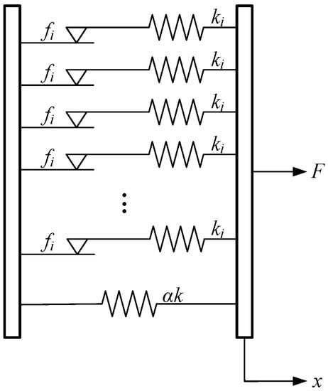
Figure 1.
Parallel–series model of the adjusted Iwan model.
The typical force-displacement hysteresis loop under cycle load of the adjusted Iwan model is shown in Figure 2 [16]. It is easy to observe that the nonlinear force-displacement relationship given by the Iwan model is similar to that of elastic-plastic materials. Due to the similarity of elements, the connection between the Iwan model and the FE model is realized by applying specific elastoplastic properties to elements.
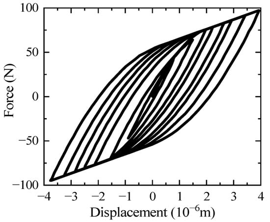
Figure 2.
Typical hysteresis loops of the adjusted Iwan model.
2.1. Adaption of Iwan Model
Since the equivalent model based on the material requires a uniaxial stress-strain curve rather than a force-displacement curve, adaption of the Iwan model definition is necessary to fit the targeting elastoplastic model. According to the expressions in Ref. [16], assuming that coefficient β is equal to 1, the force-displacement formula of the adjusted Iwan model is
in which f represents fully-slide tension, k is stiffness of force direction, α is residual stiffness ratio and x = 2f/k can be regarded as yield point by analogy. For the part of the x < x, it can be likened to the material in the elastic stage. For the part of x > x, it can be likened to the material in the plastic stage. The ‘Elastic’ part of this formula contains nonlinearity, that is, the elastic limit does not coincide with the proportional limit. It is not suitable for common material constitution; therefore, linearization is necessary to fit the constitutive equation.
Accuracy and briefness should both be considered in linearization. A linearization referring to the least square method is constructed. Let the area encircled by lines x = x, y = F(x), y = 0 be S, and the area encircled by lines x = x, y = xF(x)/x, y = 0 be S. Then x is solved when S = 0.95S. x is defined as the advanced yield point of the Iwan-based material, which is
Equation (1) will turn into
where . The stress-strain curve generated by Equation (3) is used for adaption, which is still simple and convenient for subsequent calculation.
A virtual uniform section bar is set for force-stress transition. Regarding Equation (3) as the uniaxial load result of this virtual bar, giving A and l as area and length, putting stress as δ and plastic strain as ε, as shown in Equation (4), into Equation (3), the stress-strain relationship for the virtual bar can be obtained as shown in Equation (5).
where .
The first derivative and the second derivative are given as Equations (6) and (7).
Equations (6) and (7) above are implicit. To get a proper value for δ′ and δ″, the total strain should be solved firstly from Equations (4) and (5), as shown in Equation (8).
where . Equations (6) and (7) can be calculated more easily by substituting total strain ε for ε.
2.2. FEM Realization of the Iwan-Based Material
According to Ref. [47], a universal approach of elastoplastic material FEM realization is given below.
For kinematic hardening elastoplastic material, its plasticity modulus E is composed of kinematic hardening part E and isotropic hardening part E, as shown in Equation (9).
in which is the stress-strain formulation of uniaxial tension, often achieved by tests.
With yield condition:
E, with respect to can be solved with the Newton iteration method. Afterwards, update equations for the shift tensor η, stress σ, plastic strain and other variables are shown in Equation (11).
The partial derivative of kinematic hardening modulus E with respect to is shown in Equation (12).
The constitutive equation of combined hardening material is shown in Equation (13).
According to these equations, one specific material can be defined as long as its uniaxial loading curve is provided. Besides, the distribution rules between isotropic and kinematic part of plastic modulus can be obtained.
2.3. Algorithm Realization and Procedure
The constitutive relation of the Iwan-based material can be obtained by associating the two parts above together. The stress-strain relationship described by Equation (5) is regarded as the relationship described by Equation (9). If , then the variables in Equations (10), (11) and (13) change as shown in Equation (14).
The constitutive law and the FEM algorithm of the Iwan-based material are defined by Equations (5) (10), (11), (13) and (14).
The complete algorithm of the proposed equivalent modeling method is given in the form of a flow chart, demonstrated in Figure 3. The values in Equation (14) and the corresponding yield stress values are given by the IWANHARD function.
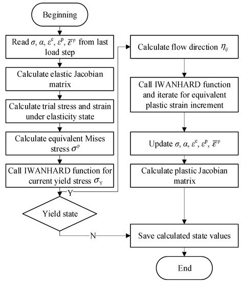
Figure 3.
Flow chart of the proposed modeling method.
3. Method Validation
The proposed equivalent modeling method is implemented by subroutines in ABAQUS. A basic FEM calculation is performed to verify its function. Usage and limitations of this method are also discussed in the following sections.
3.1. Comparison with the Traditional Iwan Model
A minimal model is used to avoid unnecessary disturbance from complicated model geometry and loading states. This minimal model is based on Song’s [16] adjusted Iwan beam element (AIBE); the parameters of the adjusted Iwan model are shown in Table 1, and the sizes of the jointed beam structure are illustrated in Figure 4. The equivalent model using the proposed Iwan-based material is in a state of uniaxial tension, as shown in Figure 4. It is a regular hexahedron whose size is the same as that of the jointed beam structure. The axial displacement and the rotation perpendicular to the axis are set to zero on one side, and an alternating displacement is applied to another side. After this setting, the equivalent model is in a uniaxial stress state at all stages of loading, which is the same as the boundary condition of the AIBE in the hysteresis calculation.

Table 1.
Parameters used for the adjusted Iwan model.
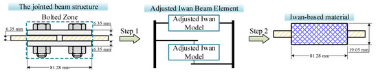
Figure 4.
Equivalent method of the bolted connection. Step 1: replace the bolted zone with the adjusted Iwan model; Step 2: the adjusted Iwan model is equivalent to a regular hexahedron using the Iwan-based material.
A UMAT subroutine and its corresponding functions are written in FORTRAN and called in ABAQUS serving as the Iwan model properties’ provider. Based on an universal kinematic elastoplastic material, the subroutine is programmed according to Section 2. A function with typical hardening properties of the Iwan model is called when UMAT needs it. The result and the comparison are respectively illustrated in Figure 5a,b.
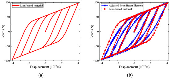
Figure 5.
(a) the hysteretic loops calculated by the Iwan-based material; (b) comparison of hysteretic loops obtained by two modeling methods.
Due to the uniaxial loading condition, the stress nephogram has only one non-zero stress component with uniform stress values over all elements. The above results indicate that the performance of the Iwan-based material under uniaxial loading is similar to that of the Ref. [16]. Both results have few differences in the initial loading stage but are different in the cycle loading stage. The slopes of both results are same at the beginning of each cycle loading step. The misalignment observed in Figure 5b transits from initial stiffness to residual stiffness. These differences stem mainly from the linearization method described in Section 2.1, which extends the linear part of the force-displacement curve during unloading and reloading. The two curves have similar maximum and minimum force values in the residual stiffness part. The slight offset in the reloading part is due to the error of cycle loading displacements in the Ref. [16], whose minimum displacement does not reach the exactly abstract value of maximum loading. The slope of the hysteresis loops of the AIBE is smaller than that of the hysteresis loops of the equivalent model. The slope of the original force-displacement curve of the Iwan model decreases gradually [16], and there is no linear segment. In order to match the curve with a similar material model, the curve segment with a small slope change is changed into a straight line by the equivalent model. After the cyclic loading stage, this effect was more obvious, which resulted in the difference in calculation results.
3.2. Comparison with the Refined FE Model
Compared with the simulation results and the experimental results of a detailed 3D FE model, the simulation effect of the equivalent method on the real bolted connection is verified. A 3D bolted connection with the bolt head fixed is selected as the model from Ref. [48] and simulated in detail under cycling transverse displacement. The model used is shown in Figure 6. Displacements of 0.3 mm and 0.06 mm were applied at the edge of the movable top plate to simulate the external force perpendicular to the bolt axis. The experimental results are obtained under the maximum transverse displacement of 0.3 mm for the movable top plate, and the simulation results are obtained by FEM under the maximum transverse displacement of 0.3 mm and 0.06 mm. These results are then compared with those obtained by the equivalent model.
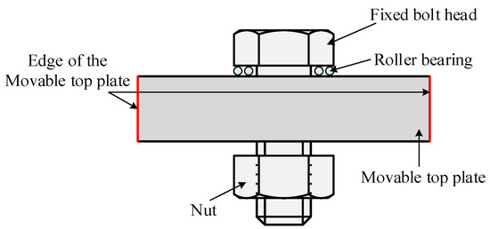
Figure 6.
The detailed 3D model of the bolted connection described in Ref. [48].
The detailed 3D FE model is a single bolt-nut set, surrounded by clamped boards, and all contact surfaces are considered, including external threads of bolts and internal threads of nuts. Compared with the common method of applying bolt preload, this modeling method which completely considers the threads is more accurate to simulate bolted connections, so it has considerable reference value [48]. When the equivalent modeling is carried out for this detailed 3D FE model, similar to the AIBE, the local part of the bolted connection is selected for analysis, so it has high comparability. For the calculation of the equivalent model, a similar minimum model is selected in Section 3.1, and its parameters and loads remain unchanged. The proper values of the minimum model can be calculated from the result curve in the Ref. [48]. Since it is unnecessary to keep the equivalent area the same as the original one, the parameters A and l are set to be the same as those in Section 3.1. Then the residual parameters can be determined by Equation (3) to form the result curves. The parameters for calculation are listed in Table 2.
Table 2.
Parameters of the equivalent model under different transverse displacements.
The comparison between the results of the Ref. [48] and calculation results of hysteresis loops are plotted in Figure 7.
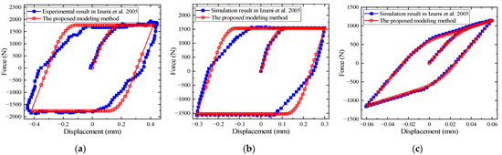
Figure 7.
Comparisons between the equivalent modeling method and the results under different transverse displacements: (a) comparison of experimental results under 0.3 mm transverse displacement; (b) comparison of simulation results with FEM under 0.3 mm transverse displacement; (c) comparison of simulation results with FEM under 0.06 mm transverse displacement [48].
The comparison indicate that the calculation results of the equivalent model fit well with the simulation results of the detailed finite element model in the Ref. [48]. Especially under the cyclic loading of 0.06 mm transverse displacement, the calculation results of the two are basically consistent. When the structure is subjected to the cyclic loading of 0.3 mm transverse displacement, the force-displacement curve of the equivalent model in the initial loading stage is basically consistent with the experimental and simulation results of the detailed 3D FE model [48]. However, in the cyclic loading stage, the transition stage of the connection stiffness from no-slip state (the slope of the force-displacement curve is almost constant) to complete slip state (the slope of the force-displacement curve is zero) is slightly different from the Iwan model. The reasons for these differences have been explained above.
The Iwan model can effectively simulate the case of overall slippage and complete loss of connection stiffness, but the accuracy is lower than that of small slippage. As can be seen from the above results, the equivalent modeling method based on the Iwan-based material is especially suitable for the case of small transverse displacements and only the micro-slip of connection interfaces in bolted connections.
4. Discussions
4.1. Physical Meanings of Modeling Parameters
Although the proposed modeling method of bolted connections is based on a phenomenological formula, its parameters are still relevant to physical settings. Therefore, it has a certain physical significance.
A series of experimental results published in the Ref. [49] are selected to reveal the relationship between the parameter F and the bolt preload. According to this experiment, plates connected with a single bolt are tensioned and compressed from the free ends on both sides; the model is shown in Figure 8. Experimental results show the hysteresis cycles under different levels of the bolt preload. The bolt preload is expressed by the relative preload, and the expression of β is shown in Equation (15).
where Fcl is the applied bolt preload and Fy is the yield strength.
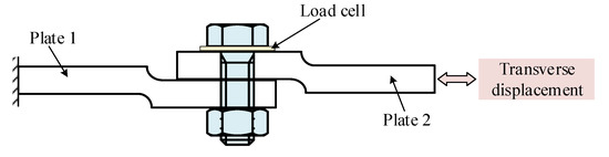
Figure 8.
Bolted lap joint described in Ref. [49].
The corresponding parameters of the equivalent model can be determined by the same method in Section 3.2, which are consequently listed in Table 3. Experimental and analytical results of each level of the relative preload are demonstrated in Figure 9. It can be observed that there is a good congruity between experimental results and analytical results. Therefore, the discussion of the physical meanings of the modeling parameters is reasonable.
Table 3.
Parameters of equivalent model under different levels of bolt preload.
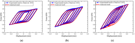
Figure 9.
Comparisons under different levels of bolt preload: (a) comparison of 57% bolt preload; (b) comparison of 77% bolt preload; (c) comparison of 90% bolt preload [49].
From the results given in Table 3 and Figure 9, it can be seen that the parameters F and α are significantly changed with the relative preload β. Figure 10 shows that the two parameters increase with the relative preload, which indicates that the two parameters raise nonlinearly. When the relative preload is large, the ratio of growth is also great.
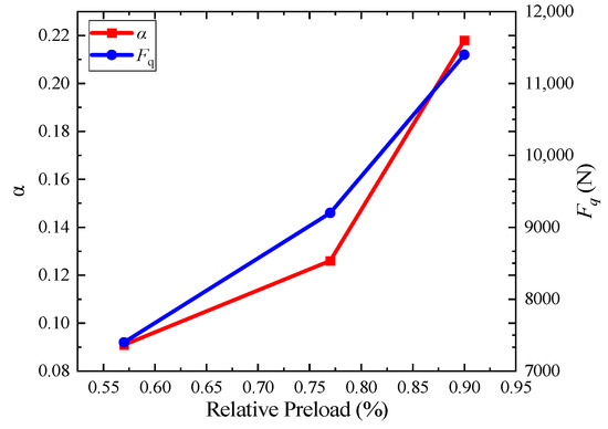
Figure 10.
Parameters altering with the relative preload.
This result is not surprising because of the similar characteristics between the Iwan model and the bolted connection. As shown in Figure 1, the Iwan model is derived from friction, which is also the major source of the hysteresis behavior of the bolted connection. According to the Coulomb friction law, the critical sliding force is positively correlated with the vertical force applied on the interface. At the same time, the friction force grows with the increase of the vertical force, resulting in the shift ratio of stiffness. Therefore, the critical sliding force F and the residual stiffness ratio α will change with the applied bolt preload. However, the nonlinear characteristics of the growth suggest that the internal mechanism should be more complicated than the Coulomb friction.
Nevertheless, the parameters F and α cannot be determined directly from the bolt preload when other factors related to the friction are unknown. However, when the hysteresis loops of a certain bolt preload is known, the correlation relationship between two forces is helpful to predict F under other levels of bolt preload.
4.2. Limitation of the Equivalent Modeling Method
A fundamental feature of this modeling method is that the connection section is equivalent to an isotropic material with nonlinearity. The application and limitations of the proposed modeling method are analyzed.
Since the material used in this method is isotropic, the equalized connection section can be subject to loads in any direction, so it can be applied to the simulation of complex structures. This feature can guarantee availability but cannot ensure accuracy. Its stiffness in different directions is correlative because of the applied range of the proposed material, that is, the connection stiffness in different directions is coupled. This coupling relationship makes the equivalent model able only to guarantee the accuracy of the Iwan model parameters in a certain direction, but it cannot take into account all directions, when the size of the equivalent region remains unchanged. Besides, the directional stiffness of actual connection may not correspond to the simplified model due to the change of the bolt-clamping force. This problem can be solved by redesigning the geometric sizes or shapes of the equivalent model. The size of the equivalent model does not have to be consistent with its real geometric size, but needs to be determined by the relative size of the connection stiffness at different positions of the nodes. In this way, the connection stiffness in all directions can be simulated by stiffness parameters of the Iwan model. However, this scheme cannot solve the coupling problem of slip force Fq and residual stiffness ratio α, so this scheme has limitations. Extending the Iwan-based material to anisotropic material is a way to solve the coupling problem fundamentally.
The nonlinearity of bolted connections considered by the Iwan model is derived from the investigation and simulation for slip characteristics of contact interfaces, which is mainly reflected in the contact, friction and slip of the connection interfaces [27]. The loads are transmitted through the friction between contact pairs of bolted joints designed for shear loads, and the force-displacement relationships are similar to that of the Iwan model. Therefore, the equivalent modeling method is more suitable for the case of bolted joints under the tangential load of screw.
In the axial direction of the bolted connection, the nonlinearity is mainly reflected in the difference of tension and compression stiffness. When the joint is strained, its stiffness is reflected as the stiffness of the screw. When the joint is pressed, its stiffness is the superposition of the screw stiffness and the stiffness of the connected part. The nonlinearity caused by the inconsistency of tension and compression stiffness is different from the nonlinearity embodied in the Iwan model. Therefore, another limitation of the equivalent modeling method is that it is not suitable for bolted connections which are designed mainly under tensile loads. The difference between the two designs of bolted connections limits the applicability of the Iwan-based material.
5. Conclusions
In this paper, a new equivalent modeling method based on the Iwan model is introduced by proposing a material, which is an elastoplastic material with properties of specified Iwan model. ABAQUS and its subroutine module are developed, and simulation and experiments are used to verify the proposed equivalent modeling method. The conclusions are as follows:
- The proposed Iwan-based material can represent the mechanical properties of the adjusted Iwan model, which can well characterize the nonlinearity of bolted connections.
- The Iwan-based material is effective in the modeling of bolted connections. This modeling method using the Iwan-based material can be applied to the traditional finite element modeling code with convenience.
- This equivalent method is appropriate for modeling the performance of the bolted joints under the transverse cyclic load according to the force-displacement properties of the Iwan model.
Author Contributions
Conceptualization, X.H. and D.J.; methodology, X.H. and M.W.; software, M.W. and Y.S.; validation, X.H. and M.W.; formal analysis, X.H.; investigation, X.H.; resources, D.J.; data curation, M.W. and Y.S.; writing—original draft preparation, X.H.; writing—review and editing, D.J.; visualization, M.W. and Y.S.; supervision, D.J.; project administration, D.J.; funding acquisition, D.J. All authors have read and agreed to the published version of the manuscript.
Funding
This research was funded by the National Natural Science Foundation of China (Grant Number 52202445), Natural Science Foundation of Jiangsu Province (Grant Number BK20220406), National Natural Science Foundation of China (Grant Number 11602112), Natural Science Research Project of Higher Education in Jiangsu Province (Grant Number 20KJB460003) and the Qing Lan Project.
Institutional Review Board Statement
Not applicable.
Informed Consent Statement
Not applicable.
Data Availability Statement
Not applicable.
Conflicts of Interest
The authors declare no conflict of interest.
References
- Jiang, D.; Shi, Q.F.; Fei, Q.G.; Wu, S.Q. Stiffness identification of fixed bolted-joint interface. Guti Huojian Jishu/J. Solid Rocket Technol. 2014, 37, 688–693. [Google Scholar]
- Jiang, D.; Wu, S.Q.; Shi, Q.F.; Fei, Q.G. Parameter identification of bolted-joint based on the model with thin-layer elements with isotropic constitutive relationship. Zhendong Yu Chongji/J. Vib. Shock 2014, 33, 35–40. [Google Scholar]
- Jiang, D.; Wu, S.Q.; Shi, Q.F.; Fei, Q.G. Contact interface parameter identification of bolted joint structure with uncertainty using thin layer element method. Gongcheng Lixue/Eng. Mech. 2015, 32, 220–227. [Google Scholar]
- Chen, J.; Wang, H.; Yu, Y.; Liu, Y.; Jiang, D. Loosening of Bolted Connections under Transverse Loading in Timber Structures. Forests 2020, 11, 816. [Google Scholar] [CrossRef]
- Tian, Y.; Qian, H.; Cao, Z.; Zhang, D.; Jiang, D. Identification of Pre-Tightening Torque Dependent Parameters for Empirical Modeling of Bolted Joints. Appl. Sci. 2021, 11, 9134. [Google Scholar] [CrossRef]
- Zhuang, Z.; Yu, Y.; Liu, Y.; Chen, J.; Wang, Z. Ultrasonic Signal Transmission Performance in Bolted Connections of Wood Structures under Different Preloads. Forests 2021, 12, 652. [Google Scholar] [CrossRef]
- Zhou, J.; Xu, L.; Zhang, A.; Hang, X. Finite element explicit dynamics simulation of motion and shedding of jujube fruits under forced vibration. Comput. Electron. Agric. 2022, 198, 107009. [Google Scholar] [CrossRef]
- Li, W.; Zhu, D.; Shao, W.; Jiang, D. Modeling of Internal Geometric Variability and Statistical Property Prediction of Braided Composites. Materials 2022, 15, 5332. [Google Scholar] [CrossRef]
- Xu, Y.; Liu, J.; Wan, Z.; Zhang, D.; Jiang, D. Rotor Fault Diagnosis Using Domain-Adversarial Neural Network with Time-Frequency Analysis. Machines 2022, 10, 610. [Google Scholar] [CrossRef]
- Segalman, D.J.; Starr, M.J. Inversion of Masing models via continuous Iwan systems. Int. J. Non-Linear Mech. 2008, 43, 74–80. [Google Scholar] [CrossRef]
- Argatov, I.I.; Butcher, E.A. On the Iwan models for lap-type bolted joints. Int. J. Non-Linear Mech. 2011, 46, 347–356. [Google Scholar] [CrossRef]
- Festjens, H.; Chevallier, G.; Dion, J.L. Nonlinear model order reduction of jointed structures for dynamic analysis. J. Sound Vib. 2014, 333, 2100–2113. [Google Scholar] [CrossRef]
- Dai, J.; Xu, Z.-D.; Gai, P.-P.; Hu, Z.-W. Optimal design of tuned mass damper inerter with a Maxwell element for mitigating the vortex-induced vibration in bridges. Mech. Syst. Signal Process. 2021, 148, 107180. [Google Scholar] [CrossRef]
- Süß, D.; Willner, K. Investigation of a jointed friction oscillator using the Multiharmonic Balance Method. Mech. Syst. Signal Process. 2015, 52–53, 73–87. [Google Scholar] [CrossRef]
- Iwan, W.D. A Distributed-Element Model for Hysteresis and Its Steady-State Dynamic Response. J. Appl. Mech. 1966, 33, 893–900. [Google Scholar] [CrossRef]
- Song, Y.; Hartwigsen, C.J.; McFarland, D.M.; Vakakis, A.F.; Bergman, L.A. Simulation of dynamics of beam structures with bolted joints using adjusted Iwan beam elements. J. Sound Vib. 2004, 273, 249–276. [Google Scholar] [CrossRef]
- Mignolet, M.P.; Song, P.; Wang, X.Q. A stochastic Iwan-type model for joint behavior variability modeling. J. Sound Vib. 2015, 349, 289–298. [Google Scholar] [CrossRef]
- Shiryayev, O.V.; Page, S.M.; Pettit, C.L.; Slater, J.C. Parameter estimation and investigation of a bolted joint model. J. Sound Vib. 2007, 307, 680–697. [Google Scholar] [CrossRef]
- Rajaei, M.; Ahmadian, H. Development of generalized Iwan model to simulate frictional contacts with variable normal loads. Appl. Math. Model. 2014, 38, 4006–4018. [Google Scholar] [CrossRef]
- Wang, D.; Xu, C.; Fan, X.; Wan, Q. Reduced-order modeling approach for frictional stick-slip behaviors of joint interface. Mech. Syst. Signal Process. 2018, 103, 131–138. [Google Scholar] [CrossRef]
- Yuan, P.P.; Ren, W.X.; Zhang, J. Dynamic tests and model updating of nonlinear beam structures with bolted joints. Mech. Syst. Signal Process. 2019, 126, 193–210. [Google Scholar] [CrossRef]
- Li, D.; Xu, C.; Kang, J.; Zhang, Z. Modeling tangential friction based on contact pressure distribution for predicting dynamic responses of bolted joint structures. Nonlinear Dyn. 2020, 101, 255–269. [Google Scholar] [CrossRef]
- Brake, M.R.W. A reduced Iwan model that includes pinning for bolted joint mechanics. Nonlinear Dyn. 2016, 87, 1335–1349. [Google Scholar] [CrossRef]
- Miller, J.D.; Dane Quinn, D. A two-sided interface model for dissipation in structural systems with frictional joints. J. Sound Vib. 2009, 321, 201–219. [Google Scholar] [CrossRef]
- Ahmadian, H.; Rajaei, M. Identification of Iwan distribution density function in frictional contacts. J. Sound Vib. 2014, 333, 3382–3393. [Google Scholar] [CrossRef]
- Lacayo, R.M.; Allen, M.S. Updating structural models containing nonlinear Iwan joints using quasi-static modal analysis. Mech. Syst. Signal Process. 2019, 118, 133–157. [Google Scholar] [CrossRef]
- Li, C.; Jiang, Y.; Qiao, R.; Miao, X. Modeling and parameters identification of the connection interface of bolted joints based on an improved micro-slip model. Mech. Syst. Signal Process. 2021, 153, 107514. [Google Scholar] [CrossRef]
- Li, C.; Miao, X.; Qiao, R.; Tang, Q. Modeling method of bolted joints with micro-slip features and its application in flanged cylindrical shell. Thin-Walled Struct. 2021, 164, 107854. [Google Scholar] [CrossRef]
- Wang, S.; Zhu, M.; Cao, H.; Xie, X.; Li, B.; Guo, M.; Li, H.; Xu, Z.; Tian, J.; Ma, D. Contact Pressure Distribution and Pressure Correction Methods of Bolted Joints under Mixed-Mode Loading. Coatings 2022, 12, 1516. [Google Scholar] [CrossRef]
- Wang, S.A.; Zhu, M.; Xie, X.; Li, B.; Liang, T.X.; Shao, Z.Q.; Liu, Y.L. Finite Element Analysis of Elastoplastic Elements in the Iwan Model of Bolted Joints. Materials 2022, 15, 5817. [Google Scholar] [CrossRef]
- Ahmadian, H.; Jalali, H. Identification of bolted lap joints parameters in assembled structures. Mech. Syst. Signal Process. 2007, 21, 1041–1050. [Google Scholar] [CrossRef]
- Ahmadian, H.; Jalali, H.; Pourahmadian, F. Nonlinear model identification of a frictional contact support. Mech. Syst. Signal Process. 2010, 24, 2844–2854. [Google Scholar] [CrossRef]
- Quinn, D.D. Modal analysis of jointed structures. J. Sound Vib. 2012, 331, 81–93. [Google Scholar] [CrossRef]
- Jamia, N.; Jalali, H.; Taghipour, J.; Friswell, M.I.; Haddad Khodaparast, H. An equivalent model of a nonlinear bolted flange joint. Mech. Syst. Signal Process. 2021, 153, 107507. [Google Scholar] [CrossRef]
- Ranjan, P.; Pandey, A.K. Modeling of pinning phenomenon in Iwan model for bolted joint. Tribol Int 2021, 161, 107071. [Google Scholar] [CrossRef]
- Ranjan, P.; Pandey, A.K. Iwan Model for Bolted Joint with Residual Macroslip Stiffness and Pinning. In Lecture Notes in Mechanical Engineering; Springer: Singapore, 2022; pp. 311–318. [Google Scholar]
- Ge, T.; Xu, Z.-D.; Guo, Y.-Q.; Huang, X.-H.; He, Z.-F. Experimental Investigation and Multiscale Modeling of VE Damper Considering Chain Network and Ambient Temperature Influence. J. Eng. Mech. 2022, 148, 04021124. [Google Scholar] [CrossRef]
- Lacayo, R.M.; Deaner, B.J.; Allen, M.S. A numerical study on the limitations of modal Iwan models for impulsive excitations. J. Sound Vib. 2017, 390, 118–140. [Google Scholar] [CrossRef]
- Moore, K.J.; Kurt, M.; Eriten, M.; Dodson, J.C.; Foley, J.R.; Wolfson, J.C.; McFarland, D.M.; Bergman, L.A.; Vakakis, A.F. Nonlinear Parameter Identification of a Mechanical Interface Based on Primary Wave Scattering. Exp. Mech. 2017, 57, 1495–1508. [Google Scholar] [CrossRef]
- Gross, J.; Armand, J.; Lacayo, R.M.; Reuss, P.; Salles, L.; Schwingshackl, C.W.; Brake, M.R.W.; Kuether, R.J. A Numerical Round Robin for the Prediction of the Dynamics of Jointed Structures. In Dynamics of Coupled Structures; Springer International Publishing: Berlin/Heidelberg, Germany, 2016; Volume 4, pp. 195–211. [Google Scholar]
- Li, Y.; Hao, Z. A six-parameter Iwan model and its application. Mech. Syst. Signal Process. 2016, 68–69, 354–365. [Google Scholar] [CrossRef]
- Li, Y.; Hao, Z.; Feng, J.; Zhang, D. Investigation into discretization methods of the six-parameter Iwan model. Mech. Syst. Signal Process. 2017, 85, 98–110. [Google Scholar] [CrossRef]
- Oldfield, M.; Ouyang, H.; Mottershead, J.E. Simplified models of bolted joints under harmonic loading. Comput. Struct. 2005, 84, 25–33. [Google Scholar] [CrossRef]
- Firrone, C.M.; Battiato, G.; Epureanu, B.I. Modeling the Microslip in the Flange Joint and Its Effect on the Dynamics of a Multistage Bladed Disk Assembly. J. Comput. Nonlinear Dyn. 2018, 13, 011011. [Google Scholar] [CrossRef]
- Chu, Y.; Wen, H.; Chen, T. Nonlinear Modeling and Identification of an Aluminum Honeycomb Panel with Multiple Bolts. Shock Vib. 2016, 2016, 1276753. [Google Scholar] [CrossRef]
- Abdollahzadeh, G.R.; Yapang-Gharavi, S.; Hoseinali-Beygi, M. Combination of mechanical and informational modeling to predict hysteresis behavior of I beam-to-CFT column connection. Struct. Des. Tall Spec. Build. 2018, 27, e1420. [Google Scholar] [CrossRef]
- Zou, Y.; Yun, G.; Zhuang, Z. Development of combined hardening model for the metal material under cyclic loading. In CMESM 2006: Proceedings of the 1st International Conference on Enhancement and Promotion of Computational Methods in Engineering Science and Mechanics; Jilin University: Changchun, China, 2006; pp. 515–519. [Google Scholar]
- Izumi, S.; Yokoyama, T.; Iwasaki, A.; Sakai, S. Three-dimensional finite element analysis of tightening and loosening mechanism of threaded fastener. Eng. Fail. Anal. 2005, 12, 604–615. [Google Scholar] [CrossRef]
- Abad, J.; Medel, F.J.; Franco, J.M. Determination of Valanis model parameters in a bolted lap joint: Experimental and numerical analyses of frictional dissipation. Int. J. Mech. Sci. 2014, 89, 289–298. [Google Scholar] [CrossRef]


Disclaimer/Publisher’s Note: The statements, opinions and data contained in all publications are solely those of the individual author(s) and contributor(s) and not of MDPI and/or the editor(s). MDPI and/or the editor(s) disclaim responsibility for any injury to people or property resulting from any ideas, methods, instructions or products referred to in the content. |
© 2023 by the authors. Licensee MDPI, Basel, Switzerland. This article is an open access article distributed under the terms and conditions of the Creative Commons Attribution (CC BY) license (https://creativecommons.org/licenses/by/4.0/).