Abstract
Hydrogen is receiving growing interest as an energy carrier to facilitate the shift to a green economy. However, hydrogen may cause the significant degradation of mechanical properties of structural materials, premature strain localisation, crack nucleation, and catastrophic fracture. Therefore, mechanical testing in hydrogenating conditions plays a vital role in material integrity assessment. Digital image correlation (DIC) is a versatile optical technique that is ideally suited for studying local deformation distribution under external stimuli. However, during mechanical testing with in situ electrochemical hydrogen charging, gas bubbles inherent to hydrogen recombination are created at the sample surface, causing significant errors in the DIC measurements, and posing significant challenges to researchers and practitioners utilising this technique for testing in harsh environments. A postprocessing technique for the digital removal of gas bubbles is presented and validated for severe charging conditions (−1400 mV vs. Ag/AgCl) under monotonic and cyclic loading conditions. Displacement fields and strain measurements are produced from the filtered images. An example application for measuring the crack tip opening displacement during a slow strain rate tensile test is presented. The limitations of the technique and a comparison to other bubble mitigation techniques are briefly discussed. It was concluded that the proposed filtering technique is highly effective in the digital removal of gas bubbles during in situ electrochemical hydrogen charging, enabling the use of DIC when the sample surface is almost completely obscured by gas bubbles.
1. Introduction
With the increasing impact of climate change, hydrogen has become an attractive candidate for use as an energy carrier during the global transition to a green economy. With 8800 of subsea natural gas transport pipelines on the Norwegian continental shelf, Norway has a strong privileged position to facilitate large-scale hydrogen gas transport through the conversion of the existing natural gas pipeline network into hydrogen gas transport. Most of these pipelines consist of API X52-X70 steel. In the envisioned reconversion of these pipes from natural gas into pressurised hydrogen gas transport, hydrogen may enter the pipe material from both the inner wall due to the high-pressure gas environment and the external surface, as electrochemical hydrogen charging is common to all subsea systems employing Cathodic Protection (CP) systems to inhibit corrosion [1]. The absorbed hydrogen diffuses and clusters near-susceptible microstructural features and regions of high hydrostatic stresses, causing loss of ductility [2,3,4,5], a reduction in fracture toughness [6,7,8,9] and an increase in the fatigue crack growth rate [10,11,12]. Instrumentation is difficult for testing in in situ hydrogen charging environments, often requiring specialised equipment. Particularly, practitioners have faced considerable challenges with strain measurements for many years, since it is impossible to use a conventional clip-on extensometer inside an electrolytic cell [13]. A direct (or alternate) current potential drop (DCPD or ACPD, respectively) method is a convenient tool that is commonly used to monitor the initiation and propagation of a crack in air under in situ charging conditions in a corrosive environment [10] or in hydrogen gas [14]. However, this does not say anything about the strain and its local distribution in the specimen or around the crack [15]. The same applies to setups where the specifically designed or adapted extensometers or crack opening displacement (COD) gauges are used. Therefore, it has long been critical to use new experimental methods to calibrate crack tip stress and strain distributions where the strong gradients of the microstructure evolve under load [16]. In this respect, Digital Image Correlation (DIC) is a low-cost, in situ, full-field, noncontact method that requires only the optical imaging of the specimen surface to enable both global and local displacement measurements by tracking unique features on the specimen surface. DIC has been used extensively in the past decade for a broad variety of materials, testing methods, and environments [17,18,19,20,21,22,23]. A major challenge in utilising DIC when testing in an electrolyte is the recombination of hydrogen molecules on the surface, which leads to the formation of gas bubbles, particularly at high polarisation potentials or current densities. These bubbles block the view of the specimen surface, and hinder the observation of the DIC pattern in the given region. Additionally, the bubbles are not stable; they tend to detach from the surface and flow upwards along the specimen, creating dynamic distortions in the pattern, thus causing the correlation algorithm and consequently the entire DIC analysis to fail. Zhang [18] used a twice-subtraction method to reduce the distortions caused by bubbles during a stress corrosion cracking test. Cheng et al. [19] performed notched tensile testing on mooring chain steel under in situ electrochemical charging conditions using a speckle-patterned coating as an input for the DIC algorithm, with the secondary effect of acting as an inhibitor of hydrogen uptake, thus reducing the formation of bubbles and resulting in data loss in only the limited regions. In this short communication, a simple and efficient method for digitally filtering bubbles from images aiming at DIC analysis is presented. Examples of applications of the proposed method for both monotonic and cyclic loading are shown for uncoated specimens exposed to aggressive electrochemical charging, and ways to further improve the technique are suggested.
2. Materials and Methods
Two different experimental setups for either Slow Strain Rate Testing (SSRT) or Fatigue Crack Growth Rate (FCGR) testing, using different materials and camera magnifications, were used to demonstrate the versatility of the bubble removal method under both monotonic and cyclic loading conditions.
SSRT was performed on a flexible pipe steel armour wire material whose properties were described elsewhere [24]. Single Edge Notch Tension (SENT) specimens with the geometry shown in Figure 1a were tested. The specimens were conventionally machined, while the 4 mm deep notch with a notch root radius of 180 was prepared with Electrical Discharge Machining (EDM). The random high-contrast pattern for DIC was created by manually grinding the surface down to P1200 SiC paper (Struers, Copenhagen, Denmark) before applying discernible scratches in random directions with rougher P120 SiC paper (Struers, Copenhagen, Denmark) (in the authors’ experience, using a scratch pattern yields improved resolution compared to speckle patterns, as particularly obvious in the cyclic test performed under high magnification). In order to reduce the oversaturation in the obtained images, a piece of office paper was placed in front of the light source to disperse the light.
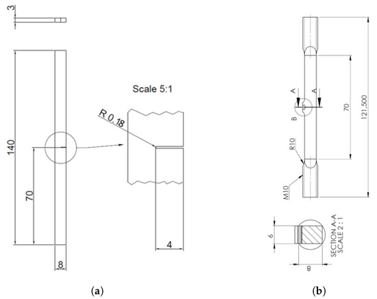
Figure 1.
Specimen geometries used for testing (all units in mm). (a) Geometry of SENT specimen used for SSRT [25]. (b) Geometry of SENT specimen used for cyclic testing.
The in situ electrochemical hydrogen charging was performed in 3.5 wt% NaCl at −1400 vs. Ag/AgCl (sat. KCl). Unless otherwise specified, all further potentials are with reference to Ag/AgCl (sat. KCl). Samples were precharged for 72 h in a glass container and then stored at −21 °C until testing. After mounting the specimen in the test machine, an additional 6 h of precharging was performed in a custom-built, 3D-printed electrochemical charging chamber equipped with a glass window to facilitate visual access to the specimen surface through the camera, as illustrated in Figure 2a. The chamber was mounted onto the specimen, and a tight seal was ensured with the combination of a 3D-printed gasket with Loctite 5926 silicone (Henkel Corporation, Westlake, OH, USA).
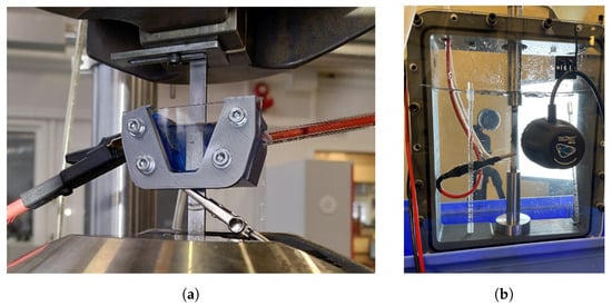
Figure 2.
Electrochemical hydrogen charging chambers used for SSRT and cyclic testing. (a) SSRT specimen installed in the 3D-printed charging chamber [25]. (b) Chamber used for cyclic testing.
The in situ SSRT tests were performed using a Landmark 50 servohydraulic universal testing machine (MTS Systems Corporation, Eden Prairie, MN, USA) with a nominal strain rate of s. Images for DIC were acquired using a 5 megapixel Prosilica GC2450 camera (Allied Vision, Stadtroda, Germany) equipped with a Tamron 272EN II macrolens (Tamron Co., Saitama, Japan) at frame rates up to 10 with a pixel size of approximately 20 .
FCGR was performed on API X65 pipeline steel using SENT specimens with the geometry shown in Figure 1b. The DIC pattern was created in a similar manner to the SSRT. The specimen surface was manually ground to a finish of P2000 SiC paper (Struers, Copenhagen, Denmark) and then scratched with P1000 paper to create the contrasting lines. Finer paper was used in the cyclic test compared to SSRT due to the higher magnification achieved with the zoom lens. The in situ electrochemical hydrogen charging was performed through the same electrolyte and polarisation potential as that for SSRT, but in the larger charging chamber shown in Figure 2b, and mounted onto a Dartec 25 servohydraulic universal testing machine (Dartec Ltd., Stourbridge, UK) retrofitted with an Instron control system (Instron, Norwood, MA, USA). Cyclic loading was applied with a maximal load of 7 with an R ratio of 0.1 and a frequency of 1 . Images were acquired using a Basler acA4112-20 um 12 megapixel resolution camera (Basler AG, Ahrensburg, Germany) equipped with a Navitar-6000 zoom lens (Navitar Inc., Ottawa, ON, Canada) with an acquisition frequency of 20 and 10 loading cycles per one acquisition series.
As previously mentioned, gas bubbles are produced during electrochemical hydrogen charging, especially at high potentials. The detrimental effect of the bubbles is twofold. Not only do the bubbles block the view of the specimen surface, hindering the observation and the analysis of the DIC pattern, but they also move upwards along the specimen, creating dynamic distortions in the pattern and causing the analysis to fail. In order to compensate for these dynamic bubbles, a simple method was employed on the basis of the fact that the bubbles appeared in the image as darker than the scratched background pattern. By performing a pixel-by-pixel comparison of several successive images taken in a series and selecting the brightest value for each pixel, the resulting composite image had substantially improved quality for DIC analysis with only minor residual effects of the bubbles. Such an operation can be expressed through Equation (1):
where M is the composite image with the composite pixel values obtained from Equation (2) from pixel values of image frame f to f, where n is the number of frames to merge in each composite image.
For the SSRT, this was achieved using the merged image composed of 10 to 100 successive images. Since the image acquisition rate was high compared to the strain rate, there was no significant deformation that had occurred within the time of acquisition of one composite image. For the cyclic loading, the composite images were created with the acquisition of multiple cycles in succession and comparing the images corresponding to the same load in each cycle.
DIC analysis was performed using open-source NCORR [26] software (NCORR v1.2.2, Georgia Institute of Technology, Atlanta, GA, USA) for MATLAB (MATLAB V2021a, The MathWorks Inc., Natick, MA, USA) The subset radius used was in the range of 36–50 pixels with a subset spacing of up to 1 in order to reduce processing time. On the basis of the displacement fields obtained with DIC, the Crack Opening Displacement (COD) was measured along the notch flanks for multiple horizontal positions from the difference in vertical displacement on each side of the notch at the given horizontal position. The Crack Tip Opening Displacement (CTOD) was then calculated using the double clip-gauge method of [27].
3. Results
Examples of filtered composite images for monotonic and cyclic loading are shown in Figure 3 and Figure 4, respectively.
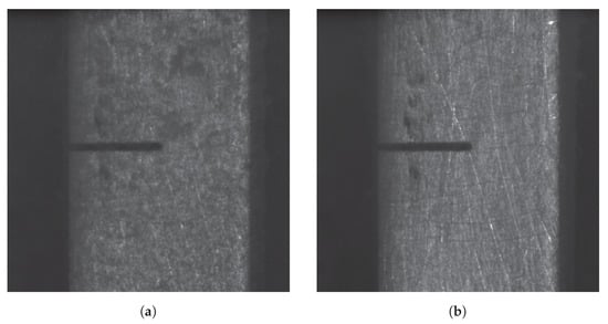
Figure 3.
Comparison of surface images for DIC before and after the digital removal of bubbles during monotonic loading. (a) Image showing specimen surface with the gas bubbles moving along it. (b) Image showing specimen surface after digitally removing the bubbles. The dark features around the notch flanks are material defects.
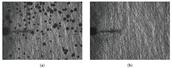
Figure 4.
Comparison of surface images for DIC before and after the digital removal of bubbles for cyclic testing. (a) Image showing specimen surface with the gas bubbles moving along it during cyclic testing. (b) Image showing specimen surface after digitally removing the bubbles during cyclic testing.
Displacement fields were easily obtained from the filtered images, as exemplified by the plots of the vertical displacements obtained during both monotonic and cyclic loading shown in Figure 5.
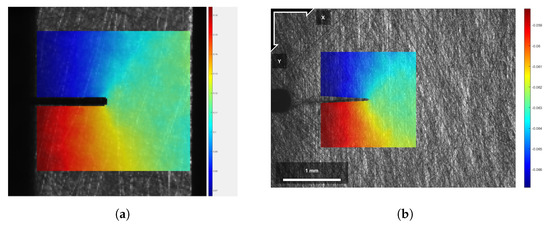
Figure 5.
Examples of displacement fields obtained after removal of bubbles during monotonic and cyclic testing. (a) Vertical displacement field during SSRT testing. (b) Vertical displacement field during cyclic testing with .
The CTOD obtained by DIC from a SSRT specimen is shown in Figure 6. Results of the full testing campaign of the steel flexible armour wires are reported elsewhere; in the present work, we confine ourselves to the methodological aspects of the challenging application of the DIC technique to mechanical testing in a harsh environment with the profuse hydrogen bubble formation.
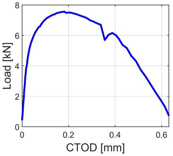
Figure 6.
Load versus CTOD from SSRT.
The method was originally developed for CTOD testing under in situ electrochemical charging conditions, and the measurements of our primary interest were the vertical displacements along the notch flanks. Due to the relatively low resolution used (approximately 400 pixels across the specimen width) and the low polarisation voltage, which lead to a near-constant production and coverage of bubbles on the specimen’s surface, the current dataset did not allow for a sufficiently detailed strain field, as a large subset radius of 36–50 pixels was necessary. Nonetheless, as a proof of concept, an example of a vertical strain field produced during SSRT is shown in Figure 7. Since the DIC technique has been well-established and widely proven in academia and industry, e.g., comparing physical or virtual extensometers [27], the results were deemed to be trustworthy. In addition, while it is not shown in the manuscript, the full SSRT testing campaign compared the Crack Mouth Opening Displacement (CMOD) results obtained with DIC in air and in hydrogen after bubble removal using the proposed method (see the results described in [25]). In the elastic regime, hydrogen is generally not thought to have an effect on the mechanical properties of the material [28], and the load–CMOD curves in hydrogen and air overlap nicely in the elastic regime, thus confirming, albeit indirectly, the validity of the DIC measurements.
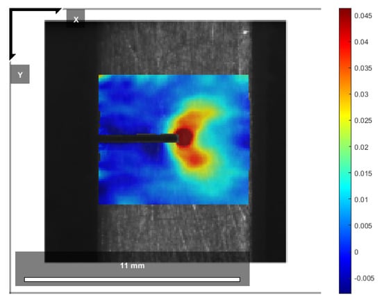
Figure 7.
Proof of concept of obtained strains on filtered images in the form of vertical strain 𝜖yy. The resolution is poor due to the large subset radius used, which is clearly seen from the large circle of maximal strain at the notch tip.
4. Discussion
A simple algorithm was developed for digitally removing the disturbance generated by the presence of bubbles on a specimen surface during in situ electrochemical hydrogen charging during monotonic and cyclic mechanical testing, enabling the use of DIC in order to allow for measurements of CTOD and local strain evolution evaluation. Two main preconditions are necessary for the procedure to work: a sufficient contrast in the grayscale values of the DIC pattern compared to the bubbles, and that negligible deformations and/or crack extensions occur between the images, which are merged together to create a composite defect-free image. As long as the number of images to be merged is not too large and the strain rate is low or the camera acquisition frame rate sufficiently high, this is a reasonable assumption. With reference to the tests types and test conditions used in the present communication for illustrative purpose, between 10 and 100 images were merged together according to the severity of the produced gas bubbles. With frame rates of at least 1 and a nominal strain rate of s, the worst case resulted in 10 displacement across the 10 gauge section during one composite frame. With a pixel size of approximately 20 , this was negligible. The number of pictures necessary to merge in order to remove the effects of the bubbles depends strongly on the severity of the charging conditions. For each pixel, the bare specimen surface must be visible in at least one image. As the charging conditions become more aggressive, the higher the density of the bubbles appearing on the surface become, and the probability of a pixel showing the specimen surface is reduced accordingly. The charging current was not measured during in the current work. For illustration, on the basis of the polarisation curves for a A537 steel [29] in a simulated seawater electrolyte, for an imposed potential of −1400 , the current density is approximately 100 times greater than those at the commonly used potential of −1100 . In other words, to have the same probability of removing all effects of bubbles at −1400 , one needs to combine about 100 times more images than those needed at −1100 .
Compared to alternative ways of mitigating the effect of bubbles on DIC results, the method developed in this work presents many advantages and a few disadvantages. The most straightforward way of mitigating bubbles is to prevent their formation in the first place by coating the specimen with paint, concurrently acting as the DIC pattern. However, a fully intact coating prevents hydrogen uptake, which would hinder the degrading effect of hydrogen on the material properties and therefore may not be of interest for most hydrogen related research. On the other hand, the coating may not provide a sufficient potential gradient to stop cathodic reactions from occurring at the surface, the coating may cathodically disbond [30] or it can have a lower failure strain than the tested material, either of which causes bubbles to appear again, disrupting the DIC pattern and the subsequent DIC results. An alternative way is to remove the bubbles mechanically, e.g., by using a fan submerged in the charging chamber to cause sufficient flow to remove the bubbles as they appear. From the authors’ previous experience, some effect of bubbles or contaminant particles flowing past the specimen still remains, especially at low potentials such as −1400 . The use of a longer exposure time, e.g., 500 , has usually proven to be sufficient to remove most of these effects. However, this may not be applicable, it may cause issues when testing at high strain rates, and it cannot effectively be used during cyclic loading due to the need for a long exposure time. The use of a fan also requires a much larger charging chamber, which may be challenging for some applications. A major benefit of the method is its suitability to both monotonic and cyclic loading. Some challenges still remain for perfectly employing it for cyclic testing, in particular at low levels for which strains are small and more susceptible to noise. Since the method requires the merging of several successive images and assumes that no deformation occurs between them, issues might arise if measurable crack propagation occurs or if the triggering of the camera is not perfectly synchronised with the load evolution during the duration of the cycles used for each acquisition. For FCGR testing, crack propagation may only be problematic in the high regime, as even for aggressive charging at −1400 , the merging of 10 pictures was sufficient, and hydrogen enhanced FCGR in low-carbon steel are typically below 1 /cycle at a high of 20 . With the high-resolution pixel size of approximately 1 μm used in this work, a crack tip drift of only 10 pixels could occur in the worst case. Many test setups are not completely stiff, and in particular for servohydraulic machines, the loading cycle may not be perfectly reproduced in each cycle. Additionally, the camera might be susceptible to vibrations from the test machine or the lab environment, especially at high magnification. As a result, nominally acquired images at the same loading point in each cycle may not be perfectly aligned one-to-one, and the merged image might, therefore, be slightly smeared, affecting the obtained results, particularly for detailed strain measurements.
5. Conclusions
- A simple method for the digital removal of bubbles from optical images during in situ electrochemical hydrogen charging was developed and demonstrated for both monotonic and cyclic loading.
- DIC was used on the filtered composite images to obtain displacement fields.
- CTOD was calculated using the displacements from DIC.
- Strain maps were possible to obtain given a sufficient resolution and motion compensation for cyclic testing.
Author Contributions
Conceptualization, A.S. and A.O.M.; methodology, A.O.M. and A.S.; software, A.O.M. and A.S.; validation, A.O.M., A.S., A.A. and A.V.; formal analysis, A.O.M.; investigation, A.O.M.; resources, A.V. and A.A.; data curation, A.O.M.; writing—original draft preparation, A.O.M.; writing—review and editing, A.O.M., A.S., A.A. and A.V.; visualization, A.O.M.; supervision, A.A. and A.V.; project administration, A.A. and A.V.; funding acquisition, A.A. and A.V. All authors have read and agreed to the published version of the manuscript.
Funding
This research was funded by Norges Forskningsråd, grant number 294739.
Data Availability Statement
Restrictions apply to the availability of the raw data. Example code implementing the bubble removal algorithm in MATLAB is available online at https://github.com/Aleksaom/BubbleRemovalDIC.
Acknowledgments
The authors would like to thank Ellen Skilbred for performing the slow strain rate testing.
Conflicts of Interest
The authors declare no conflict of interest.
Abbreviations
| CMOD | Crack Mouth Opening Displacement. |
| COD | Crack Opening Displacement. |
| CP | Cathodic Protection. |
| CTOD | Crack Tip Opening Displacement. |
| DIC | Digital Image Correlation. |
| EDM | Electrical Discharge Machining. |
| FCGR | Fatigue Crack Growth Rate. |
| SENT | Single Edge Notch Tension. |
| SSRT | Slow Strain Rate Testing. |
References
- Perng, T.P.; Wu, J.K. A Brief Review Note on Mechanisms of Hydrogen Entry into Metals. Mater. Lett. 2003, 57, 3437–3438. [Google Scholar] [CrossRef]
- Cialone, H.; Holbrook, J. Sensitivity of Steels to Degradation in Gaseous Hydrogen; ASTM International: Philadelphia, PA, USA, 1988. [Google Scholar]
- Moro, I.; Briottet, L.; Lemoine, P.; Andrieu, E.; Blanc, C.; Odemer, G. Hydrogen Embrittlement Susceptibility of a High Strength Steel X80. Mater. Sci. Eng. A 2010, 527, 7252–7260. [Google Scholar] [CrossRef]
- Ghosh, G.; Rostron, P.; Garg, R.; Panday, A. Hydrogen Induced Cracking of Pipeline and Pressure Vessel Steels: A Review. Eng. Fract. Mech. 2018, 199, 609–618. [Google Scholar] [CrossRef]
- Mostafijur Rahman, K.M.; Mohtadi-Bonab, M.A.; Ouellet, R.; Szpunar, J.; Zhu, N. Effect of Electrochemical Hydrogen Charging on an API X70 Pipeline Steel with Focus on Characterization of Inclusions. Int. J. Press. Vessel. Pip. 2019, 173, 147–155. [Google Scholar] [CrossRef]
- Wang, R. Effects of Hydrogen on the Fracture Toughness of a X70 Pipeline Steel. Corros. Sci. 2009, 51, 2803–2810. [Google Scholar] [CrossRef]
- Chatzidouros, E.V.; Papazoglou, V.J.; Tsiourva, T.E.; Pantelis, D.I. Hydrogen Effect on Fracture Toughness of Pipeline Steel Welds, with in Situ Hydrogen Charging. Int. J. Hydrog. Energy 2011, 36, 12626–12643. [Google Scholar] [CrossRef]
- Chatzidouros, E.V.; Papazoglou, V.J.; Pantelis, D.I. Hydrogen Effect on a Low Carbon Ferritic-Bainitic Pipeline Steel. Int. J. Hydrog. Energy 2014, 39, 18498–18505. [Google Scholar] [CrossRef]
- Olden, V.; Alvaro, A.; Akselsen, O.M. Hydrogen Diffusion and Hydrogen Influenced Critical Stress Intensity in an API X70 Pipeline Steel Welded Joint – Experiments and FE Simulations. Int. J. Hydrog. Energy 2012, 37, 11474–11486. [Google Scholar] [CrossRef]
- Alvaro, A.; Wan, D.; Olden, V.; Barnoush, A. Hydrogen Enhanced Fatigue Crack Growth Rates in a Ferritic Fe-3 wt%Si Alloy and a X70 Pipeline Steel. Eng. Fract. Mech. 2019, 219, 106641. [Google Scholar] [CrossRef]
- Ronevich, J.A.; Somerday, B.P.; San Marchi, C.W. Effects of Microstructure Banding on Hydrogen Assisted Fatigue Crack Growth in X65 Pipeline Steels. Int. J. Fatigue 2016, 82, 497–504. [Google Scholar] [CrossRef]
- Ogawa, Y.; Matsunaga, H.; Yamabe, J.; Yoshikawa, M.; Matsuoka, S. Fatigue Limit of Carbon and CrMo Steels as a Small Fatigue Crack Threshold in High-Pressure Hydrogen Gas. Int. J. Hydrog. Energy 2018, 43, 20133–20142. [Google Scholar] [CrossRef]
- Kampe, S.; Koss, D. The effect of stress state on the hydrogen embrittlement of nickel. Acta Metall. 1986, 34, 55–61. [Google Scholar] [CrossRef]
- Zafra, A.; Álvarez, G.; Benoit, G.; Hénaff, G.; Rodríguez, C.; Belzunce, J. Influence of hydrogen on the fatigue crack growth rate of 42CrMo4 steel welds: A comparison between pre-charge and in-situ testing. Procedia Struct. Integr. 2022, 39, 128–138. [Google Scholar] [CrossRef]
- Si, Y.; Rouse, J.; Hyde, C. Potential difference methods for measuring crack growth: A review. Int. J. Fatigue 2020, 136, 105624. [Google Scholar] [CrossRef]
- Gangloff, R.P. Critical issues in hydrogen assisted cracking of structural alloys. In Environment-Induced Cracking of Materials; Shipilov, S., Jones, R., Olive, J.M., Rebak, R., Eds.; Elsevier: Amsterdam, The Netherlands, 2008; pp. 141–165. [Google Scholar] [CrossRef]
- Sendrowicz, A.; Myhre, A.O.; Wierdak, S.W.; Vinogradov, A. Challenges and Accomplishments in Mechanical Testing Instrumented by In Situ Techniques: Infrared Thermography, Digital Image Correlation, and Acoustic Emission. Appl. Sci. 2021, 11, 6718. [Google Scholar] [CrossRef]
- Zhang, X. Effect of Bubbles on Measurement Accuracy of Digital Image Correlation for a Stress Corrosion Test. Appl. Opt. 2019, 58, 6873–6881. [Google Scholar] [CrossRef] [PubMed]
- Cheng, X.; Zhang, X.; Wu, Y.; Wang, L.; Zhao, P.; Yang, L. The Character of Hydrogen Embrittlement in Mooring Chain Steel. JOM 2020, 72, 2003–2010. [Google Scholar] [CrossRef]
- Pan, B.; Dafang, W.; Yong, X. Incremental Calculation for Large Deformation Measurement Using Reliability-Guided Digital Image Correlation. Opt. Lasers Eng. 2012, 50, 586–592. [Google Scholar] [CrossRef]
- Ktari, A.; Baccar, M.; Shah, M.; Haddar, N.; Ayedi, H.F.; Rezai-Aria, F. A Crack Propagation Criterion Based on ΔCTOD Measured with 2D-digital Image Correlation Technique: A crack propagation criterion based on ΔCTOD measured with 2D-digital image correlation technique. Fatigue Fract. Eng. Mater. Struct. 2014, 37, 682–694. [Google Scholar] [CrossRef]
- Kovac, J.; Alaux, C.; Marrow, T.J.; Govekar, E.; Legat, A. Correlations of Electrochemical Noise, Acoustic Emission and Complementary Monitoring Techniques during Intergranular Stress-Corrosion Cracking of Austenitic Stainless Steel. Corros. Sci. 2010, 52, 2015–2025. [Google Scholar] [CrossRef]
- Zhang, W.; Simpson, C.A.; Lopez-Crespo, P.; Mokhtarishirazabad, M.; Buslaps, T.; Pippan, R.; Withers, P.J. The Effect of Grain Size on the Fatigue Overload Behaviour of Nickel. Mater. Des. 2020, 189, 108526. [Google Scholar] [CrossRef]
- Skilbred, E.S.; Lootz, S.A.; Johnsen, R. Hydrogen Embrittlement Susceptibility of Steel Armor Wires for Flexible Pipes. In CORROSION; OnePetro: Richardson, TX, USA, 2020; p. NACE–2020–14489. [Google Scholar]
- Skilbred, E.S. Corrosion, Hydrogen Uptake and Environmentally Assisted Cracking of Flexible Pipe Steel Armour Wires. Ph.D. Thesis, Norwegian University of Science and Technology, Trondheim, Norway, 2022. [Google Scholar]
- Blaber, J.; Adair, B.; Antoniou, A. Ncorr: Open-Source 2D Digital Image Correlation Matlab Software. Exp. Mech. 2015, 55, 1105–1122. [Google Scholar] [CrossRef]
- Van Minnebruggen, K.; Verstraete, M.; Hertelé, S.; De Waele, W. Evaluation and Comparison of Double Clip Gauge Method and Delta 5 Method for CTOD Measurements in SE(T) Specimens. J. Test. Eval. 2016, 44, 2414–2423. [Google Scholar] [CrossRef]
- Laureys, A.; Depraetere, R.; Cauwels, M.; Depover, T.; Hertelé, S.; Verbeken, K. Use of Existing Steel Pipeline Infrastructure for Gaseous Hydrogen Storage and Transport: A Review of Factors Affecting Hydrogen Induced Degradation. J. Nat. Gas Sci. Eng. 2022, 101, 104534. [Google Scholar] [CrossRef]
- Du, X.S.; Su, Y.J.; Li, J.X.; Qiao, L.J.; Chu, W.Y. Stress Corrosion Cracking of A537 Steel in Simulated Marine Environments. Corros. Sci. 2012, 65, 278–287. [Google Scholar] [CrossRef]
- Xu, M.; Lam, C.N.C.; Wong, D.; Asselin, E. Evaluation of the Cathodic Disbondment Resistance of Pipeline Coatings—A Review. Prog. Org. Coat. 2020, 146, 105728. [Google Scholar] [CrossRef]


Disclaimer/Publisher’s Note: The statements, opinions and data contained in all publications are solely those of the individual author(s) and contributor(s) and not of MDPI and/or the editor(s). MDPI and/or the editor(s) disclaim responsibility for any injury to people or property resulting from any ideas, methods, instructions or products referred to in the content. |
© 2022 by the authors. Licensee MDPI, Basel, Switzerland. This article is an open access article distributed under the terms and conditions of the Creative Commons Attribution (CC BY) license (https://creativecommons.org/licenses/by/4.0/).