Article

Relieving Residual Stress of 316L Stainless Steel by Acoustic/Thermal Composite Treatment

School of Materials Science and Engineering, Southwest Jiaotong University, Chengdu 610031, China
*
Author to whom correspondence should be addressed.
Metals 2023, 13(1), 18; https://doi.org/10.3390/met13010018
Submission received: 24 November 2022 / Revised: 17 December 2022 / Accepted: 19 December 2022 / Published: 22 December 2022
(This article belongs to the Special Issue Mechanical Properties of Metals Welding Joints)

Abstract

:
The influence of temperature, vibration time, amplitude, and other factors on the residual stress release effect was studied using the method of low-temperature heating and high-frequency ultrasonic vibration, and excellent control parameters were obtained. In addition, the influence of cutting weld reinforcement on the residual stress release was also studied. The results demonstrate that the highest relative residual stress release rate was 280.29%, the average release was over 150 MPa, and the efficiency was higher than that of the general stress release methods. After cutting the reinforcement, only a small part of residual stress was released, influencing the overall residual stress distribution relatively little. The experimental material was a butt-welded 316L stainless steel plate μ-X360s diffractometer, and this was used for measuring the residual stress.

1. Introduction

A 316L stainless steel is a type of austenitic stainless steel [1,2,3], and its overall performance is superior to both 304 and 310 stainless steel. It is used extensively in the clock, heat exchanger, pipeline, food, and chemical industries. However, a significant amount of residual stress is generated after welding, which seriously affects the strength of component materials, which shortens the fatigue life of the workpiece, and affects the stability of the workpiece size. Therefore, residual stress control technology research has a great engineering application value. A variety of residual stress control methods have recently emerged, including the vibratory stress relief method [4], thermal stress method [5], and high-energy ultrasonic method [6]. The thermal stress method is characterised by a long cycle, high energy consumption, high cost, the easy oxidation of workpieces, serious pollution, and difficulties when handling large components or heat-damaged components. The impact method may cause new defects to the weld or even result in weld leg cracking. The residual stress elimination rate of VSR (vibration stress relief) is only approximately 50%. The high-energy ultrasonic method changes the residual stress state on the surface and inside the component, realising the local quantitative elimination of residual stress [7]. However, the average elimination rate of welding residual stress by the ultrasonic impact is less than a third. To summarise, the disadvantages of the various stress-relieving methods that are currently used are quite obvious. In comparison to the heat treatment method, the application scope is incredibly small. Table 1 lists the advantages and disadvantages of the various residual stress relief methods. It can be seen that these methods cannot take into account the characteristics of being “portable, time-saving, and effective”, and the acoustic/thermal composite control method studied in this paper can just meet these characteristics.
A great deal of plastic deformation occurs during the process of cutting materials, which significantly impacts residual stress distribution. Dong et al. recommended that the width-thickness ratio of welded joint specimens of steel should be a minimum of 6~10 as a means of retaining the welding residual stress [8,9]. Therefore, during the research process, the sample size selection is incredibly important to minimise the experimental error caused by the release of residual stress due to other factors.
Meanwhile, studies in the literature have found residual stress to be released in the partial size of the cutting material [10]. In the parallel weld direction, a larger cutting size results in the release of greater residual stress. However, few scholars have intentionally studied the specific release amount of residual stress after cutting welds. To ensure the authenticity and accuracy of experimental data, this paper studies the influence that the residual height of cutting welds has on the release of residual stress, comparing the release effect with the control treatment. At the same time, a single vibration and single heat treatment were studied, and the residual stress release effect was compared to that of the combined acoustic/thermal control method as a means of verifying whether the combined control method was better. This proves the efficiency and effectiveness of the residual stress control method in this paper.
Heating promotes uniform stress release, and vibration can enable the workpiece to absorb energy more rapidly. A combination of both can realise stress relief through simple equipment construction while also having the advantages of portability and rapidity.
Therefore, the method of low-temperature heating combined with high-frequency ultrasonic vibration is used in this paper to study the effect of residual stress relief. In addition to achieving or exceeding the effect of heat treatment, it ensures more time saving, energy saving, and convenience. It can efficiently and conveniently eliminate residual stress, thereby providing a new idea for the elimination of residual stress in the future, and it has excellent application potential.

2. Test Materials and Methods

2.1. Experimental Materials

The size of the 316L stainless steel plate was chosen as 200 × 150 × 6 mm3. The chemical composition and mechanical properties can be seen in Table 2 and Table 3.

2.2. Test Method

The filler wire was also 316L stainless steel with a 30° V groove. GTAW welding was used to weld the steel plate before welding, and GMWA welding (welding parameters can be seen in Table 4) was used for butt welding. The size following welding was 200 × 300 × 6 mm3.
The samples were controlled by low-temperature heating in combination with high-frequency ultrasonic vibration. The parameters that affected the control effect included the vibration time, amplitude, heating temperature, and frequency. As a means of reducing excess influencing factors and simplifying the experimental amount, the ultrasonic frequency was fixed at 20 KHz, and the remaining parameters can be seen in Table 5. The samples before and after regulation were cut into 4 × 10 × 20 mm3 to create metallographic samples and electron backscatter diffraction analysis samples for mechanism analysis.
The residual stress control system is shown in Figure 1.
In Figure 1b, 1 is the welded plate, 2 is the silica gel heating plate, 3 is the ultrasonic module of the ultrasonic device, 4 is the test bench, 5 is the clamping device that fixes the welded plate to the test bench, and 6 is the stable platform that supports the ultrasonic module. The ultrasonic excitation source and temperature sensor are both omitted from the figure. The specific control operation is as follows: firstly, the welded 316L stainless steel plate is placed on test bench 4 and fixed with bolts to ensure it is not able to move in a horizontal direction, and the moving distance in the vertical direction is below 1 mm. The silica gel heating plate 2 is then covered on the steel plate, and the steel plate is preheated, the holding time being greater than or equal to 15 min. The external insulation layer of the heating plate is made from a flexible heater that is produced by the ARLON Company of America, and this is a silicone rubber composite glass fibre base material. The ultrasonic excitation source is opened, the amplitude of ultrasonic wave 3 and other parameters is set, and cooperation with the insulation of the sample vibration ultimately occurs.

2.3. Residual Stress Test

Firstly, the samples are electrolytically polished, and residual stresses before and after the treatment are measured using the X-ray residual stress analyser μ-X360s (Pulstec, Hamamatsu-City, Japan). The basic principle for measuring residual stress using X-ray is Bragg’s law. The metal lattice acts as a grating and diffracts the X-ray. According to the wave interference principle, the optical path difference must be equal to an integer multiple of the wavelength:
2 d sin θ = n λ
where n is an integer, 2θ is the diffraction angle, d is the crystal plane spacing, and λ is the wavelength. When the material stress changes, the crystal plane spacing, and the diffraction angle also change. The shift in the diffraction angle 2θ can be obtained to show the shift in crystal plane spacing, and the stress value in this direction can then be calculated based on the elastic mechanics’ law.
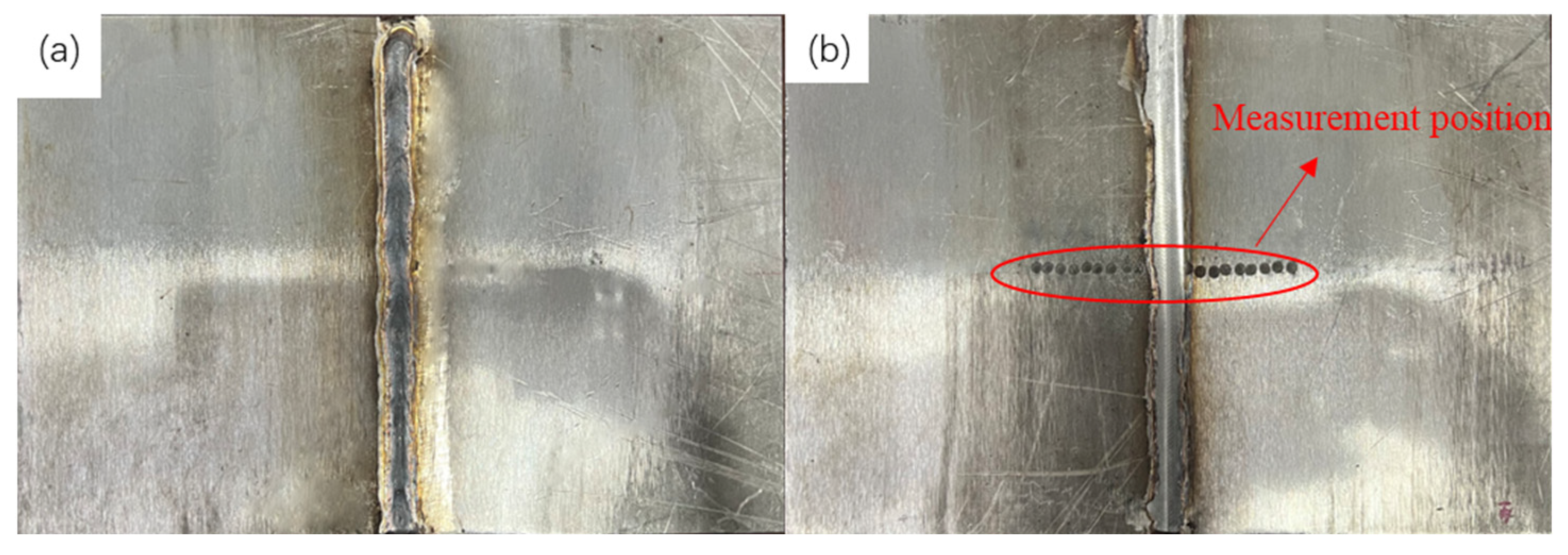
The main methods for measuring residual stress using X-ray include the 0–45° method, sin2ψ method, and cosα method. The cosα method was chosen for use in this paper, and the diffraction information of the diffraction ring (the normal strain in the direction of the Debye ring circumference angle) was collected using a two-dimensional detector in order to realise stress calculation [11]. The sample before and after the residual height was cut can be seen in Figure 2.
The X-ray diffractometer that this paper used collected most Deby-Scherrer rings and performed stress calculation [12,13]. The residual stress σx in the x-axis direction was measured according to the cosα method [14,15,16]. The test principle and equipment can be seen in Figure 3. The anode material is Mn, the spot size of the X-ray beam is 1 mm, the target peak intensity is 100, the X-ray irradiation time is 90 s, and the wavelength is K-Alpha.
The change in the near-surface residual stress of the specimen is measured was this paper, and the change in the surface residual stress in the entire process was also studied. This was to infer the change in the overall residual stress of the sample through surface residual stress change, which is why the residual stress of the positive and negative sides of the sample was measured.

3. Experimental Results

3.1. Residual Stress Distribution Change in Cutting Weld Reinforcement

The weld reinforcement should be cut by a milling machine. There are two main reasons for the change in the residual stress in the weld: first, the specimen size is changed continuously during the cutting process, so plastic deformation will occur continuously, and the residual stress of the material will be released due to the reduction in the size. Secondly, cutting at the weld position by a milling machine is a process that introduces surface compressive stress, which changes the residual stress near the weld.
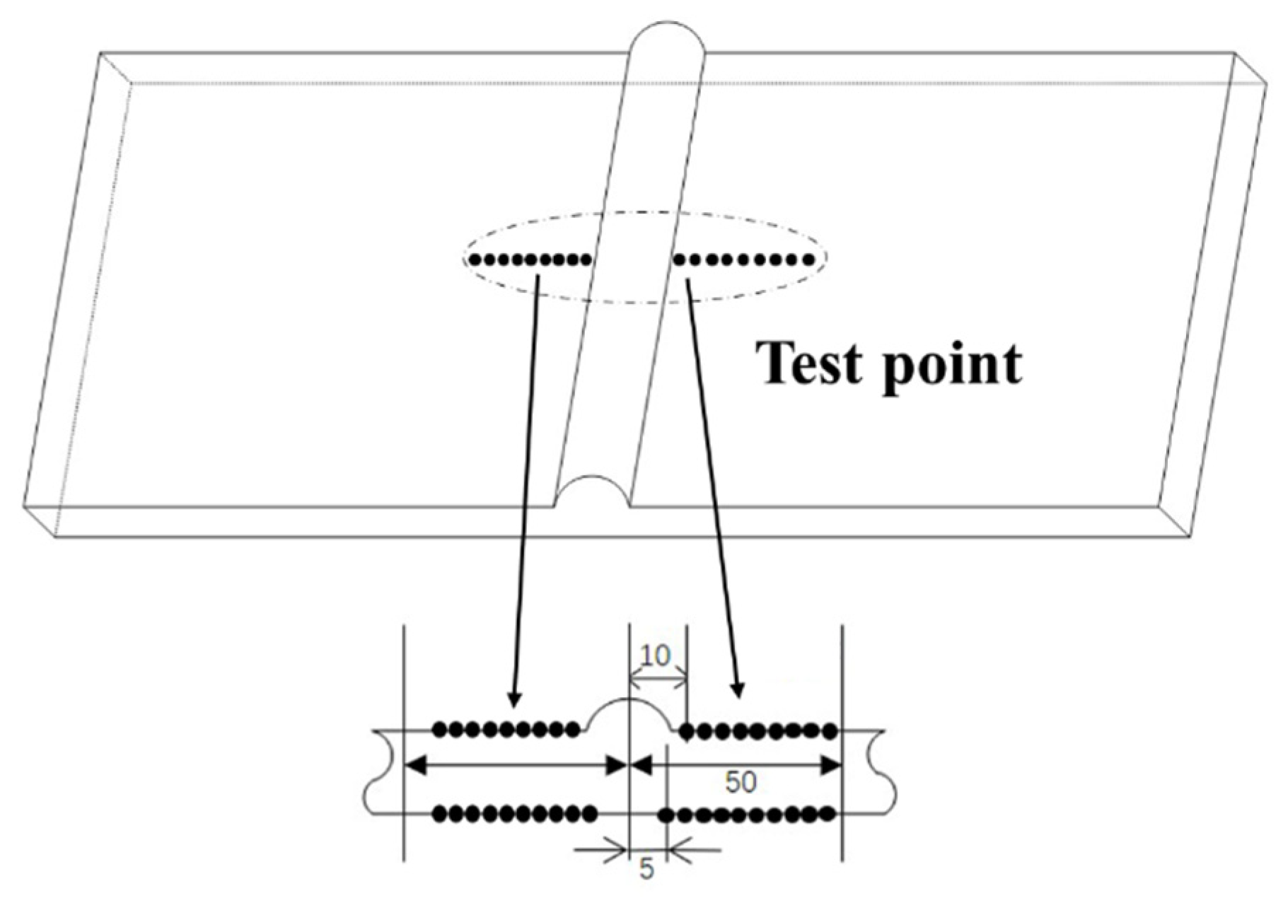
The residual stress values of approximately 50 mm near the weld width on both sides of the sample were tested. The distribution of the measurements can be seen in Figure 4. Transverse residual stress (TRS) and longitudinal residual stress (LRS) were measured vertically and parallel to the weld direction by the equipment, and the average value was taken following repeated measurements 2–3 times at each point.
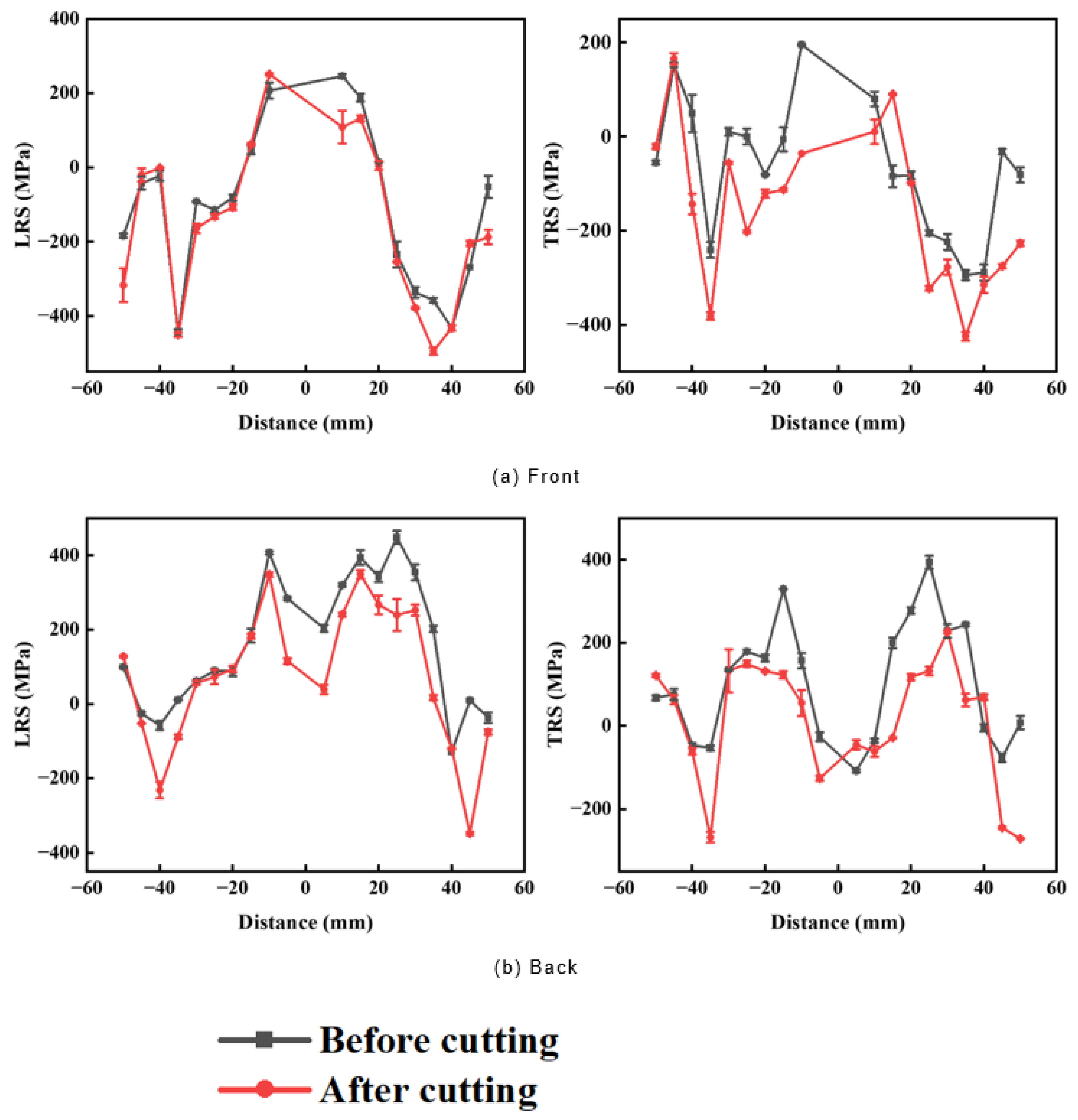
The residual stress value was measured both before and after the cutting reinforcement. As the experimental results of the seven groups of samples were found to be similar, only the residual stress distribution diagram of sample #1 is shown in Figure 5. It was stipulated that the surface with a weld residual height should be the front side.
After the residual height was cut, the residual stress of all seven groups of the samples decreased.
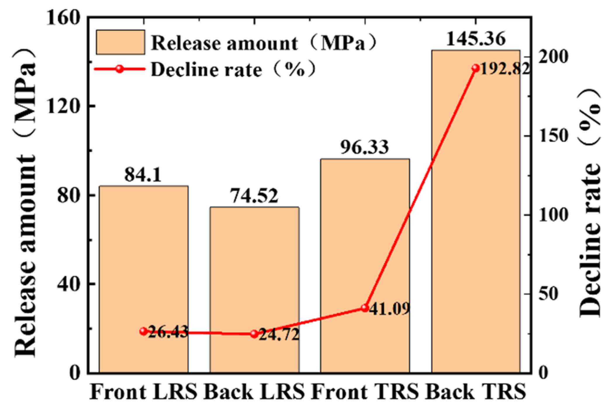
As Figure 6 shows, the peak decline rates of the vertical and horizontal peaks in the front were 55.75% and 117.91%. The average release was 84.10 MPa, and 96.33 MPa, and the highest peak reduction rates of the reverse longitudinal and transverse were 52.26% and 192.82%. The average release was 74.52 MPa and 145.36 MPa. Among them, the release amount was obtained by subtracting the adjusted value from the pre-adjusted residual stress value. The decline rate was obtained by dividing the release amount by the residual stress value before regulation.
From Figure 6, it can be seen that the residual stress released by the sample was quite obvious, and the average residual release was approximately 100 MPa.
To summarise, after the reinforcement was cut, the residual stress of the sample was released, and the residual stress reduction rate for most of the samples was below 50%. The longitudinal residual stress was relatively stable, and peak residual stress decreased by an average of 25%. The overall average release was 100.08 MPa. Therefore, the cutting allowance affected the distribution of the residual stress in the sample, but most residual tensile stress still maintained a high peak value, which would continue to be adjusted for the sample of acoustic thermal composite treatment.

3.2. Residual Stress after Acoustic/Thermal Composite Treatment

Using the same test process as Section 3.1, the residual stresses were measured before and after acoustic/thermal composite treatment, including residual stresses on the front and back sides of the seven groups of sample welds, which were discussed one by one based on different control parameters.
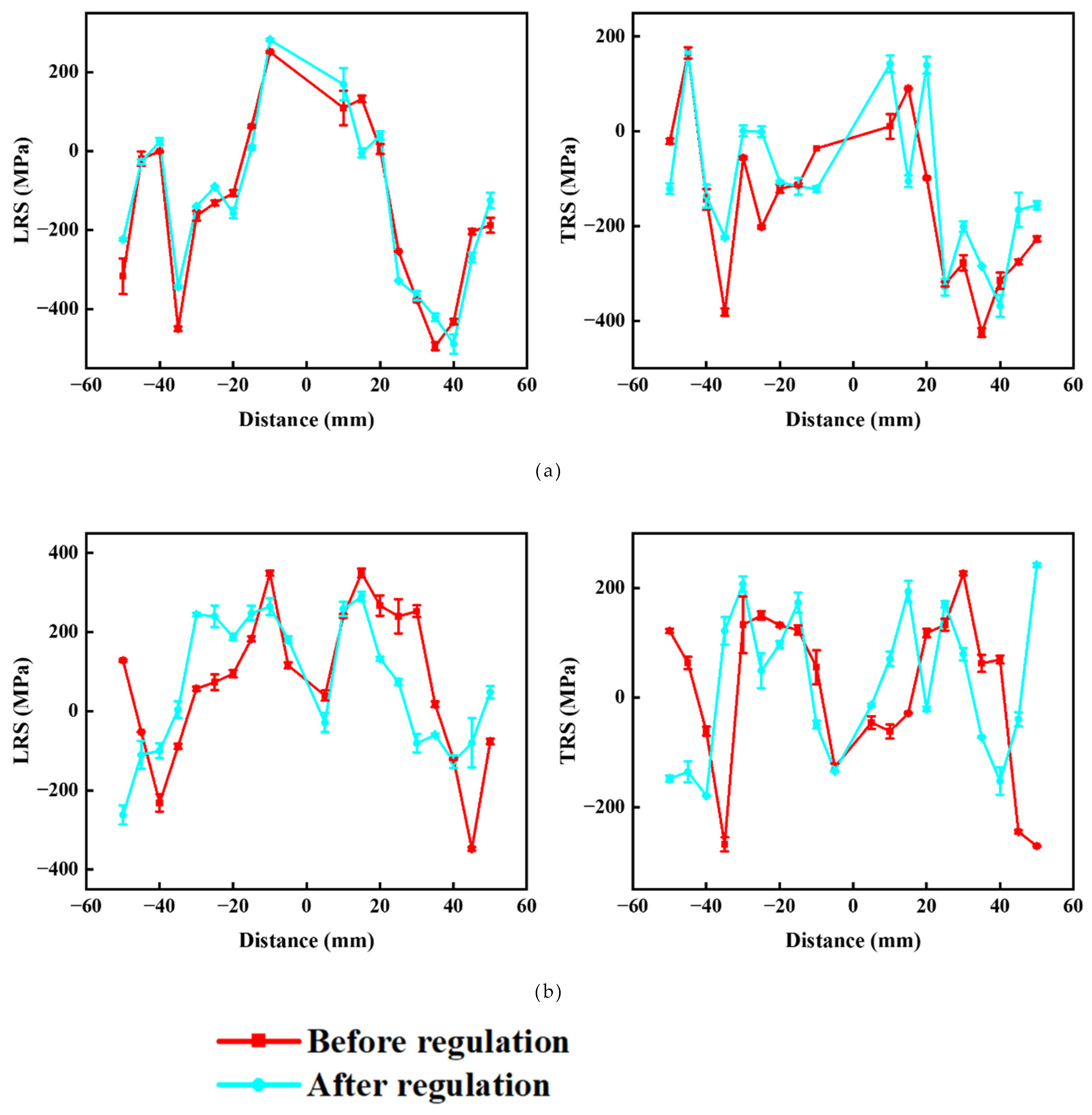
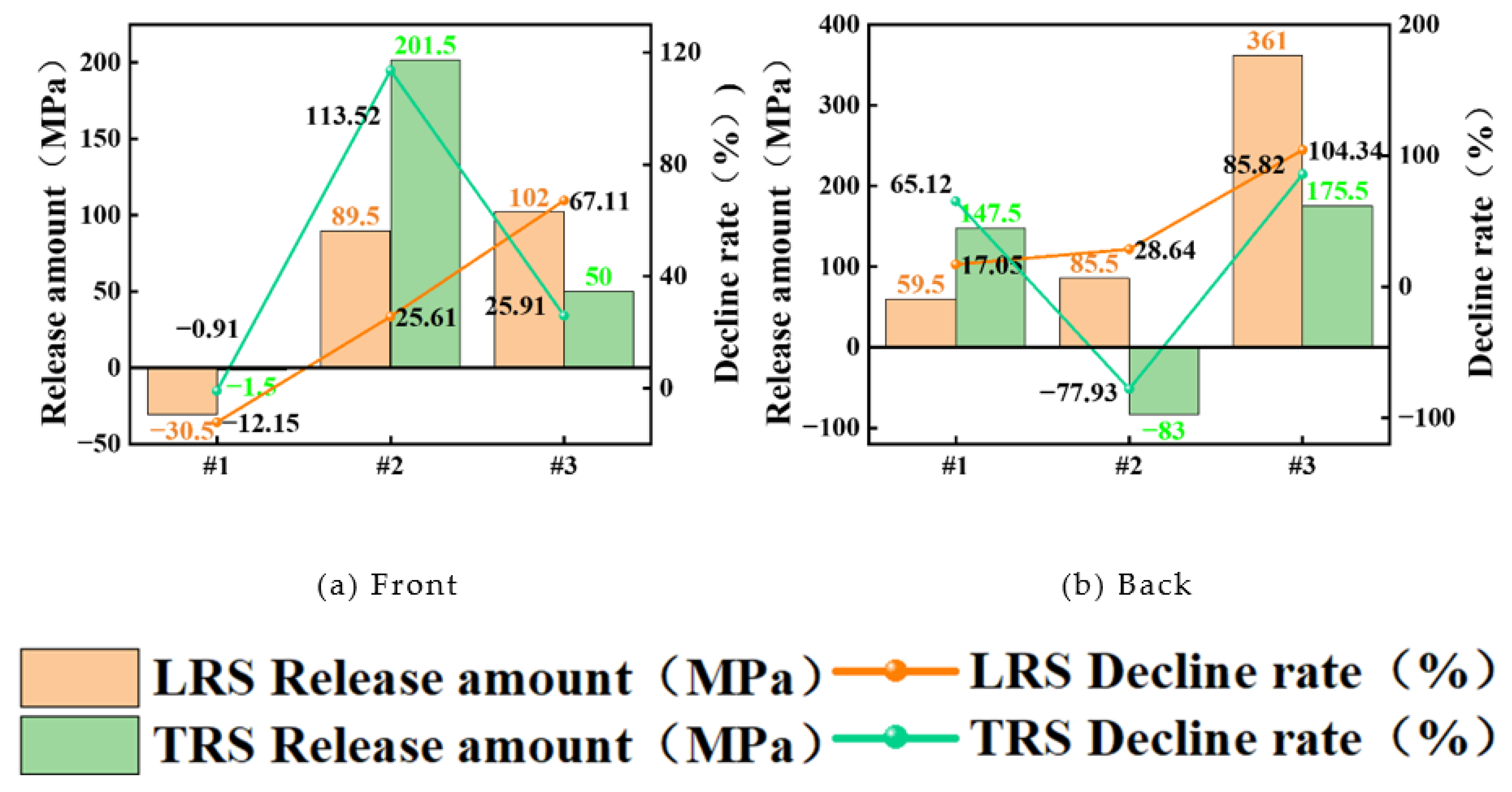
The #1, #2, and #3 samples were divided into groups, and the residual stress distribution of the #1 sample can be seen in Figure 7. The vibration time and amplitude remained unchanged, and the temperature was changed. The variation in the residual stress can be seen in Table 6 and Table 7. Adjusting to a lower temperature (sample #1) almost did not reduce the peak residual stress of the sample, and the peak residual stress increased. The above adjustment and control resulted in the redistribution of residual stress, and residual stress reduction was limited. Figure 8 shows that as the heating temperature increased from 75 °C to 125 °C, the peak residual stress reduction rate and release amount gradually increased while the value fluctuated greatly.
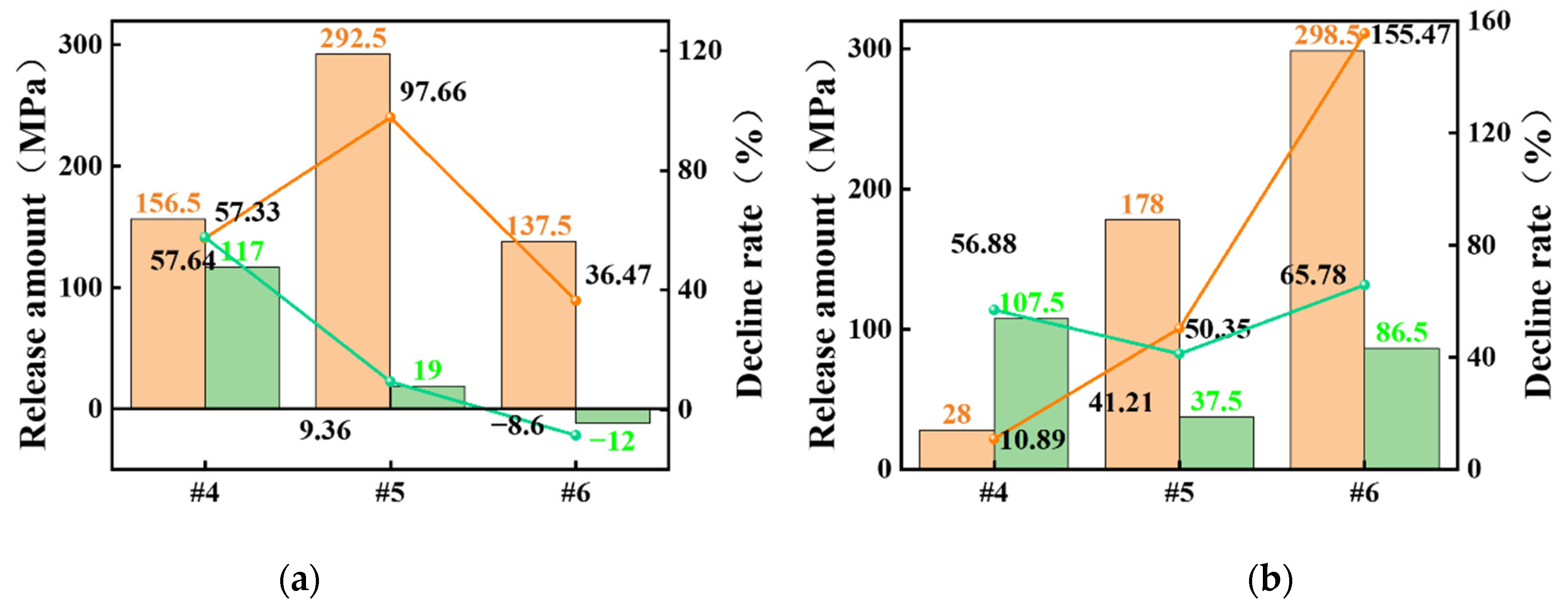
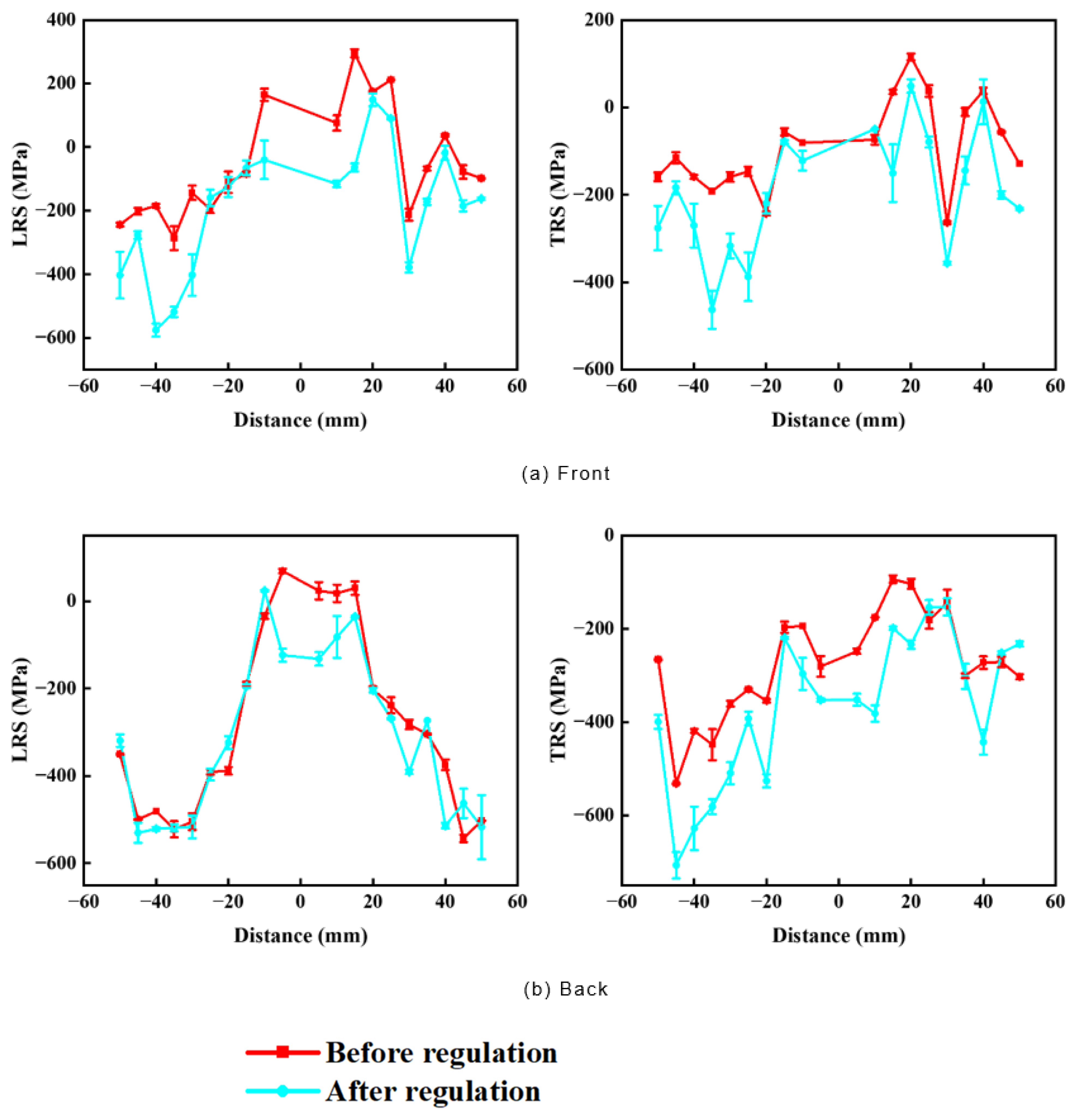
The #4, #5, and #6 samples were divided into groups, and the residual stress distribution of the #6 sample can be seen in Figure 9. The variation in the residual stress can be seen in Table 8 and Table 9. In comparison to #1, #2, and #3, the residual stress release of the last three samples increased as the vibration time and amplitude also increased. The temperature of this group of samples only increased by approximately 50 °C, while the improvement effect of residual stress was found to be significantly better than for the first three samples, which indicates that the vibration time and amplitude increase had a greater impact on the control effect of residual stress. As can be seen in Figure 10, an increased vibration time, temperature, and amplitude reduced residual stress. However, some data fluctuations are evident, which is potentially due to the mismatch between temperature and amplitude. When the amplitude energy was too high, there was insufficient time to promote the micro-plastic deformation of the weld, so this part of the impact could act on the weld in other forms.
Therefore, the vibration time of sample #7 was increased as a means of continuing the discussion to verify the conjecture.
Figure 11 shows the residual stress change curve of sample #7 and verifies the influence of the vibration time on the control effect. In comparison to the #5 and #6 specimens, the longitudinal residual stress near the weld seam was released significantly as the vibration increased over time, the effect being better than for the first six specimens. Horizontal residual stress was also released, and although this was not as large as the longitudinal residual stress, the peak residual stress was also obviously released.
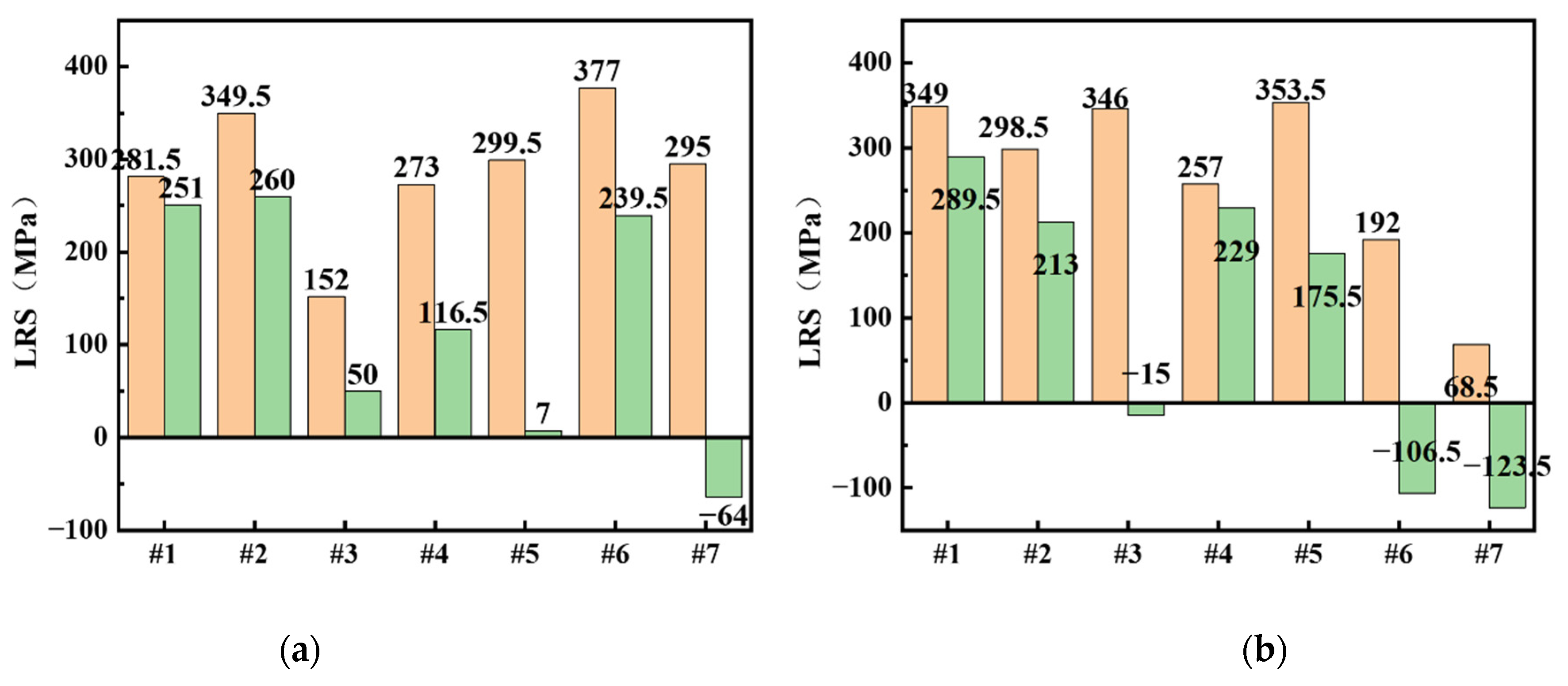
As can be seen in Figure 12, the comparison of longitudinal residual stress control effects of the seven groups of samples is listed. Compared to the peak residual stress release amount of seven samples, the longitudinal and transverse residual stresses of sample #7 were all released, and the residual tensile stresses were almost all released. Many experiments have confirmed that the longitudinal and transverse residual stresses on both sides of the sample were significantly and stably relieved under this control parameter.
In conclusion, time, heating temperature, and amplitude all affect residual stress regulation. Prior to the phase transition temperature (450 °C), the higher the temperature, the better. If the amplitude is too high and the vibration time too long, the weld will be damaged or even made invalid, so the higher the vibration time and amplitude are without damaging the weld specimen, the better it is. However, considering energy conservation, environmental protection, and the full elimination of residual stress, the #7 sample has the best parameters and most stable effect, almost completely eliminating all residual tensile stress. In comparison to the traditional residual stress control method, this saves significant time and energy costs.

3.3. Comparison of Single and Compound Regulation Effects

The effect of the composite control was quite obvious. To reflect the efficiency and authenticity of this control, the residual stress was separately controlled by the heating temperature and ultrasonic vibration.
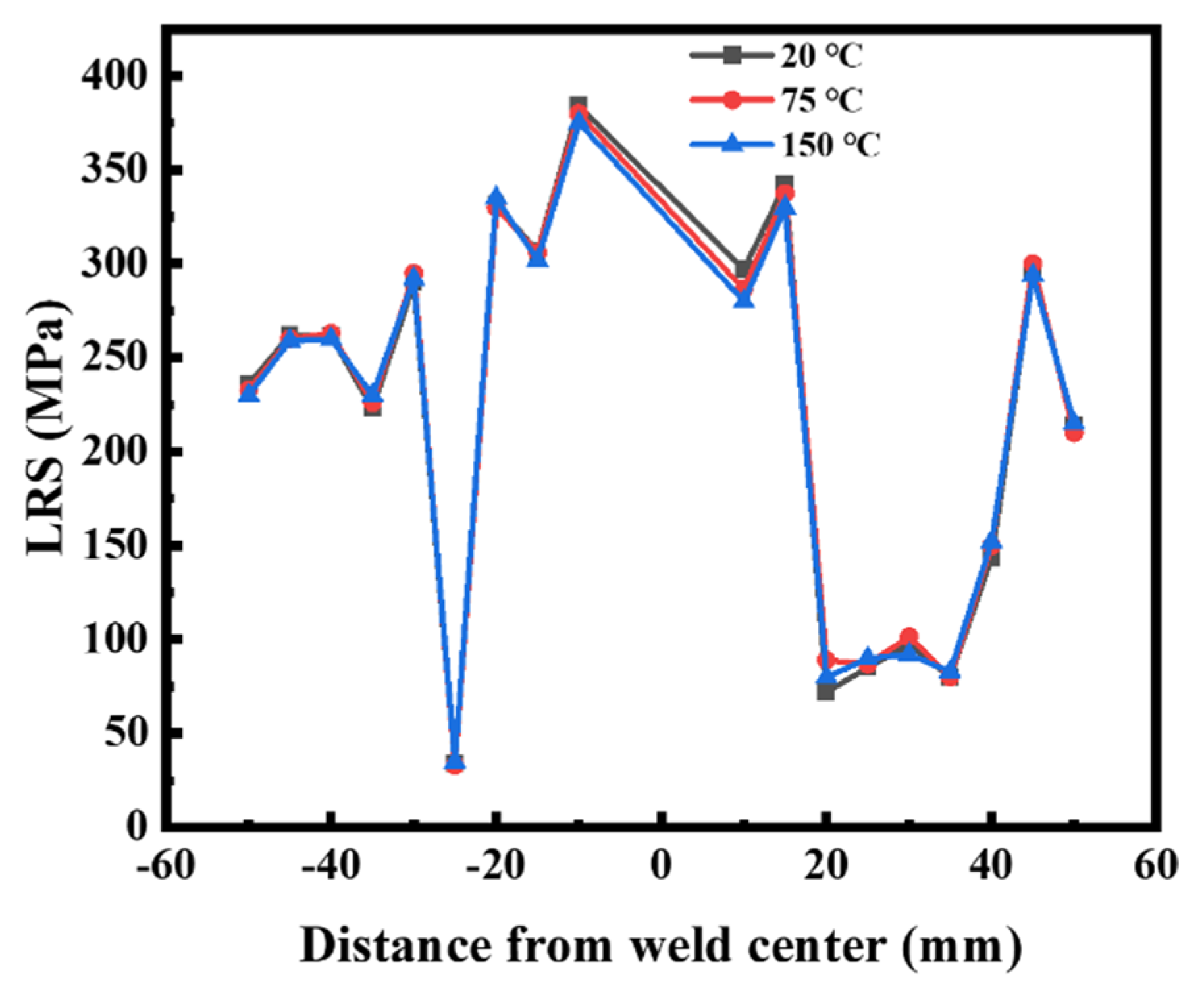
Room temperature was adjusted to 20 °C, and it was heated to 75 °C and 150 °C with a silica gel heating plate and held for 1 h before the residual stress test was conducted after it was cooled to room temperature. The test results can be seen in Figure 13. It was obvious that by using temperature heating alone, regardless of being at room temperature or in the heating state, if the temperature did not reach the phase transformation temperature of the material (chromite precipitation and austenite transformation start at 450 °C), the structure did not change, and the residual stress distribution of the sample did not change without other factors. At the same time, the physical properties of 316L stainless steel exhibited little change at a lower temperature (600 °C).
In conclusion, the use of temperature heating alone did not change the residual stress distribution of 316L stainless steel, so, therefore, this cannot be used for controlling residual stress.
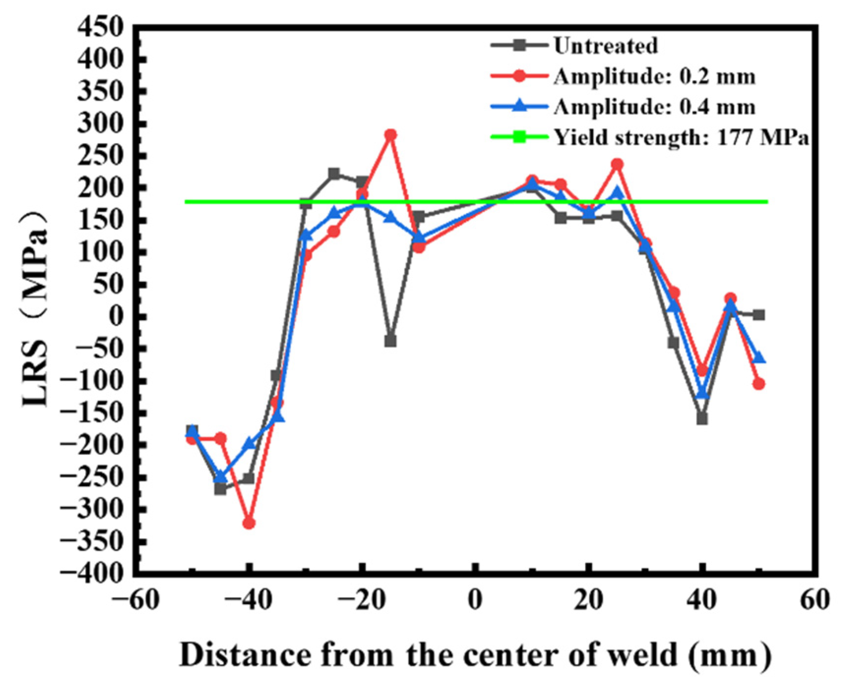
In Figure 14, the residual stress distribution of the specimen treated by ultrasonic vibration alone can be seen. The vibration time was 3 min, and the amplitude was 0.2 mm and 0.4 mm. The control effect of ultrasonic vibration alone on residual stress was found to not be good. The figure also demonstrates that the residual stress of 5 mm at the weld increased. This shows that vibration alone only caused the micro-plastic deformation of 316L stainless steel. Due to the low vibration energy and short time, deformation was low, meaning that the residual stress had little tendency to redistribute.
Therefore, when the ultrasonic vibration treatment was used alone, the residual stress in the sample was only slightly redistributed, and the elimination effect was less obvious.

3.4. Analysis and Discussion of Regulation Mechanism

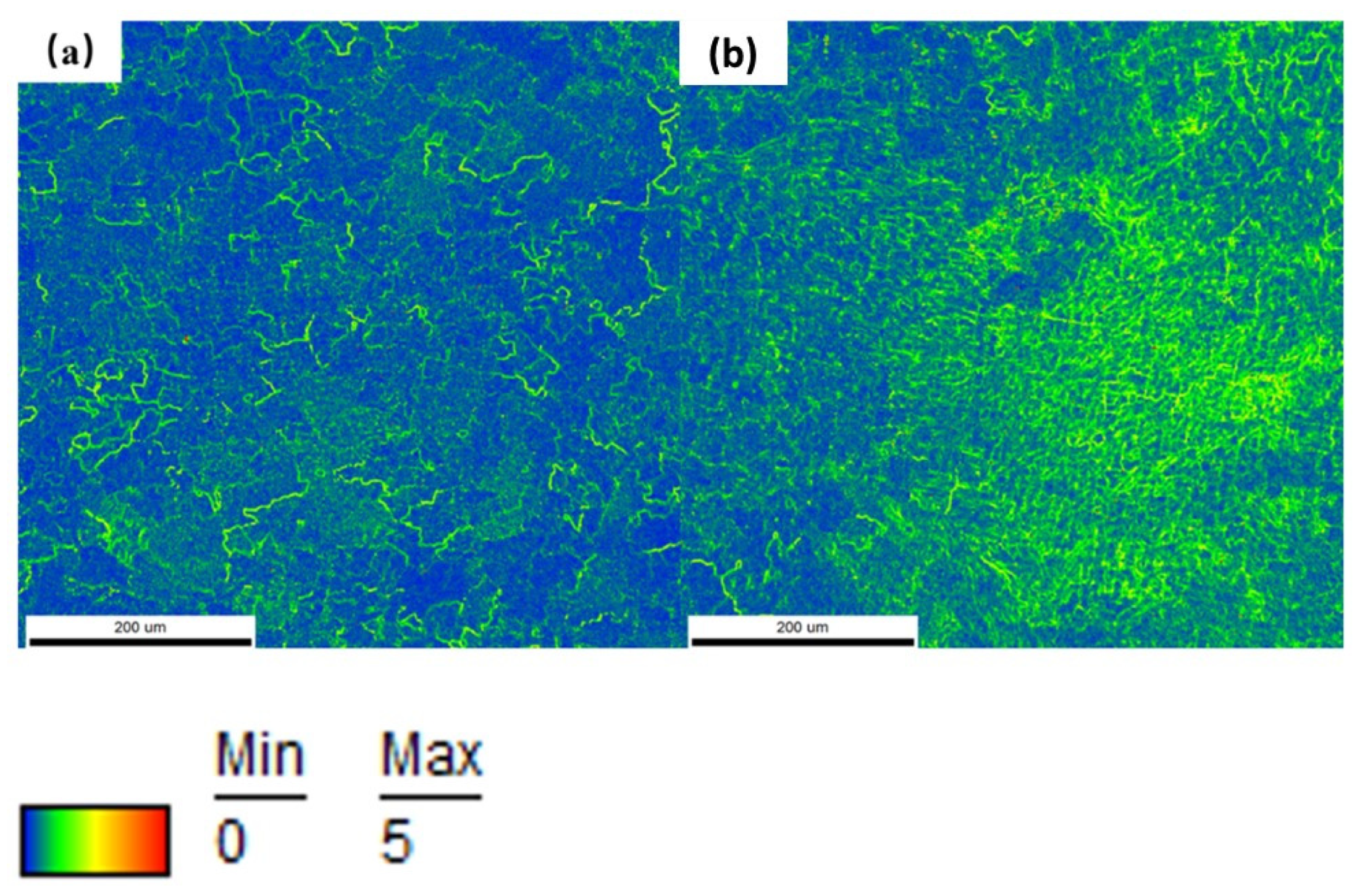
The literature [5] demonstrates that the elimination of residual stress by vibration control is related to the occurrence of the micro-plastic deformation of the sample and that it is accompanied by dislocation movement. Therefore, the welds before and after vibration were characterised by EBSD. The above view is supported by a KAM (Kerne average orientation) diagram. KAM is the average value of the orientation difference between a point in the grain and the adjacent points, which is generally used for estimating the residual strain and plastic deformation in the material [17].
As can be seen in Figure 15a,b, low-temperature heating combined with a high-energy ultrasonic impact causes a relatively weak stress concentration phenomenon in the sample, but the total stress value was small, which indicates micro-plastic deformation during the control process.
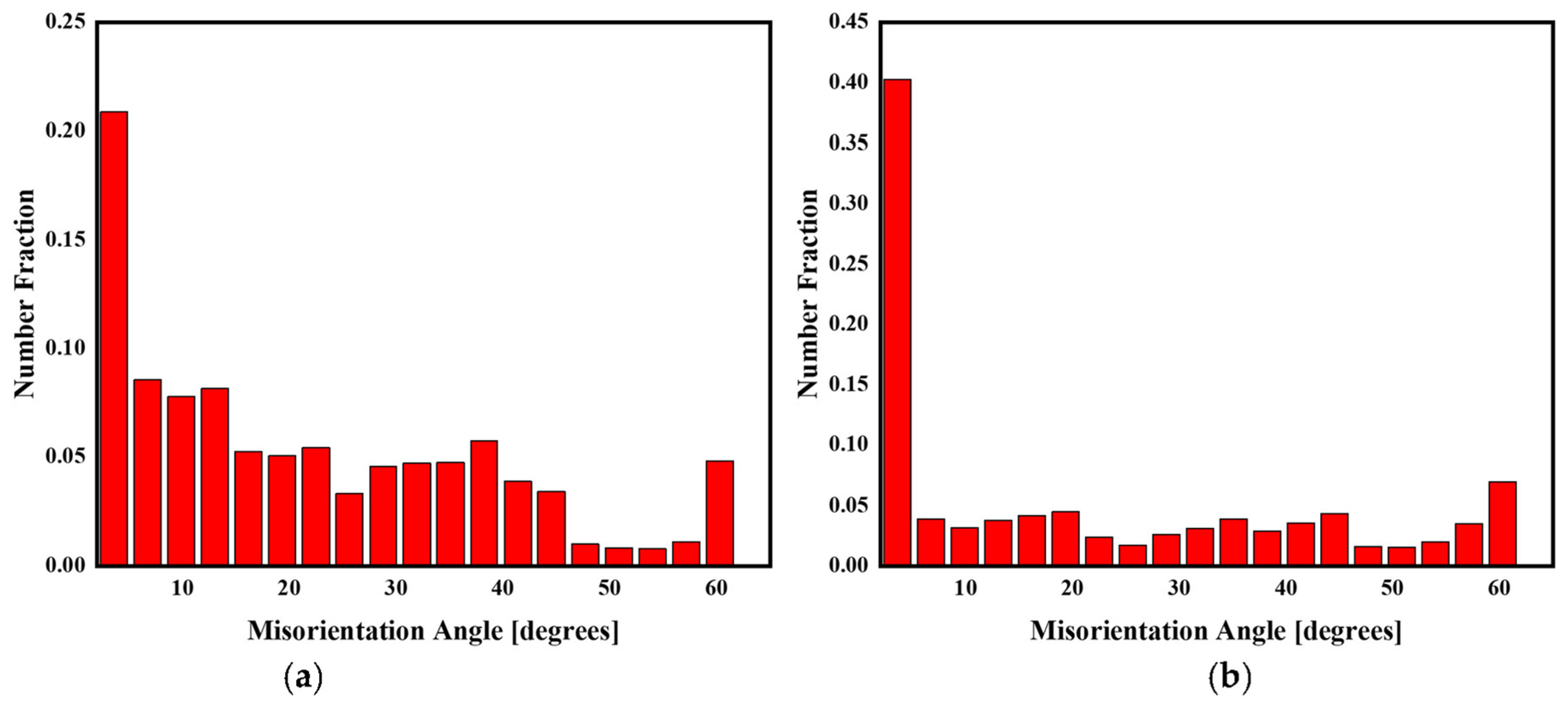
Figure 16 shows that the metallographic microstructures of the weld and its vicinity were almost the same both before and after the control. As can be seen in Figure 17, the small and medium angle grain boundaries in the weld microstructure following adjustment and control almost reached 50%; particularly, the grain boundaries at approximately 2° accounted for a high proportion, indicating many subgrains in the material, and the large angle grain boundaries gradually changed to the small angle grain boundaries, indicating that the dislocation density increased during the adjustment and control process to a certain extent.
In conclusion, a combination of low-temperature heating and high-energy ultrasonic impact properly improved the micro-plastic deformation ability of the sample, but the structure remained unchanged. Regulation caused micro-plastic deformation, which resulted in a relatively weak stress concentration in the weld area following regulation. However, generally, the stress value changed little, and the value was small. Due to the micro-plastic deformation near the weld, the residual stress in this area was released, thereby eliminating the residual stress.

4. Conclusions

The following conclusions are reached from the test and analysis results:
(1)
The influence that the weld reinforcement has on residual stress release was studied. This research found that residual stress near the weld is released after cutting the weld reinforcement, but residual stress at the weld is still the largest in relation to the overall residual stress distribution.
(2)
By changing the vibration time, heating temperature, and amplitude, the influence that acoustic/thermal composite treatment has on the residual stress of 316L stainless steel was studied. It was found that higher vibration times and temperatures resulted in better control effects. Excessive amplitude increases stress and may even result in material failure. The greater the amplitude in the range of 0.2~0.6 mm, the better the control effect.
(3)
From an energy conservation and efficiency perspective, a vibration time of 3–5 min, a heating temperature of 150–170 °C, and an amplitude of 0.4~0.6 mm can be selected as the control parameters as a means of achieving the best control effect on residual stress.
(4)
The control effect is best when the parameters of 0.6 mm amplitude, 170 °C heating, and 5 min are chosen. Residual stress near the weld is almost completely released, and the release amount reaches 359 MPa. In addition, residual stress on the positive and negative sides of the sample is released to a certain extent, and the residual stress relief effect is quite obvious.
(5)
In comparison to ultrasonic vibration and heat treatment alone, the acoustic/thermal composite treatment effect is obviously better than that of the single treatment.
(6)
The acoustic/thermal composite control results in the microplastic deformation of the material and the movement of dislocations, which causes residual stress to be released to a certain extent.
(7)
The residual compressive stress mainly exists in the area far away from the weld. From the experimental results, it can be concluded that although the stress in this part has a certain release, it has little impact on the overall service life of the sample because the failure of the sample usually occurs at the weld. Therefore, the release of residual compressive stress is unfavourable. Although it is difficult to avoid, the overall advantages are greater than the disadvantages for the experimental results.

Author Contributions

Conceptualization, Z.Z. and G.G.; methodology, P.X.; software, P.X.; validation, P.X.; formal analysis, P.X.; investigation, C.Z.; resources, G.G.; data curation, P.X.; writing—original draft preparation, P.X.; writing—review and editing, J.J.; visualization, J.J.; supervision, Z.Z.; project administration, G.G.; funding acquisition, G.G. All authors have read and agreed to the published version of the manuscript.

Funding

This research received no external funding.

Institutional Review Board Statement

Not applicable.

Informed Consent Statement

Not applicable.

Data Availability Statement

Not applicable.

Acknowledgments

Thank Gou Guoqing for the support of experimental materials.

Conflicts of Interest

The authors declare no conflict of interest.

References

  1. Zhou, L.; Nakata, K.; Tsumura, T.; Fujii, H.; Ikeuchi, K.; Michishita, Y.; Fujiya, Y.; Morimoto, M. Microstructure and mechanical properties of 316L stainless steel filling friction stir-welded joints. J. Mater. Eng. Perform. 2014, 23, 3718–3726. [Google Scholar] [CrossRef]
  2. Sun, Q.; Guo, K.; Wang, X.; Liu, J.; Sun, J. Effect of scanning strategies on the microstructure and mechanical behavior of 316L stainless steel fabricated by selective laser melting. Mater. Sci. Eng. A 2020, 793, 139879. [Google Scholar]
  3. Zong, X.W.; Liu, W.J.; Yang, Y.M. Effect of Different Molding Process on Mechanical Properties of 316L Stainless Steel. J. Phys. Conf. Ser. 2020, 1676, 012097. [Google Scholar] [CrossRef]
  4. Robinson, J.S.; Hossain, M.S.; Truman, C.E. Residual stresses in the aluminium alloy 2014A subject to PAG quenching and vibratory stress relief. J. Strain Anal. Eng. Des. 2022, 57, 167–176. [Google Scholar] [CrossRef]
  5. Song, H.; Gao, H.; Wu, Q.; Zhang, Y. Residual stress relief mechanisms of 2219 Al–Cu alloy by thermal stress relief method. Rev. Adv. Mater. Sci. 2022, 61, 102–116. [Google Scholar] [CrossRef]
  6. Zhang, Q.; Yu, L.; Shang, X.; Zhao, S. Residual stress relief of welded aluminum alloy plate using ultrasonic vibration. Ultrasonics 2020, 107, 106164. [Google Scholar] [CrossRef] [PubMed]
  7. Song, J.; Xu, C.; Li, Z. Ultrasonic nondestructive testing and regulation technology of residual stress. Mater. Sci. Eng. 2018, 397, 012136. [Google Scholar] [CrossRef] [Green Version]
  8. Jiang, W.; Woo, W.; An, G.B.; Park, J.U. Neutron diffraction and finite element modeling to study the weld residual stress relaxation induced by cutting. Mater. Des. 2013, 51, 415–420. [Google Scholar] [CrossRef]
  9. Liang, H.; Kan, Y.; Chen, H.; Zhan, R.; Wang, D. Effect of cutting process on the residual stress and fatigue life of the welded joint treated by ultrasonic impact treatment. Int. J. Fatigue 2021, 143, 105–998. [Google Scholar] [CrossRef]
  10. Khonsari, V.; Zhang, J.; Dong, P. Residual Stresses in Welded Moment Frames and Implications for Structural Performance. J. Struct. Eng. 2001, 127, 306–315. [Google Scholar] [CrossRef]
  11. Miyazaki, T.; Maruyama, Y.; Fujimoto, Y.; Sasaki, T. Improvement of X-ray stress measurement from a Debye-Scherrer ring by oscillation of the X-ray incident angle. Powder Diffr. 2015, 30, 250–255. [Google Scholar] [CrossRef]
  12. Gelfi, M.; Bontempi, E.; Roberti, R.; Depero, L. X-ray diffraction Debye Ring Analysis for STress measurement (DRAST): A new method to evaluate residual stresses. Acta Mater. 2004, 52, 583–589. [Google Scholar] [CrossRef]
  13. Kondoh, T.; Tokimasa, T.S.; Hirose, Y. X-ray stress measurement for titanium aluminide intermetallic compound. Adv. X-Ray Anal. 2000, 43, 107–116. [Google Scholar]
  14. Sasaki, T.; Hirose, Y. Single incidence X-ray stress measurement for all plane stress components using imaging plate of two-dimensional x-ray detector. J. Soc. Mater. Sci. 1995, 44, 1138–1143. [Google Scholar] [CrossRef] [Green Version]
  15. Taira, S.; Tanaka, K.; Yamasaki, T. A method of X-ray microbeam measurement of local stress and its application to fatigue crack growth problems. Jpn. Soc. Mater. Sci. 1978, 27, 251–256. [Google Scholar] [CrossRef]
  16. Sasaki, T.; Hirose, Y.; Sasaki, K.; Yasukawa, S. Influence of image processing conditions of Debye Scherrer ring images in x-ray stress measurement using an imaging plate. JCPDS-Int. Cent. Diffr. Data 1997, 2, 12–54. [Google Scholar]
  17. Yamazaki, S.; Lu, Z.; Ito, Y.; Takeda, Y.; Shoji, T. The effect of prior deformation on stress corrosion cracking growth rates of Alloy 600 materials in a simulated pressurized water reactor primary water. Corros. Sci. 2008, 50, 835–846. [Google Scholar] [CrossRef]
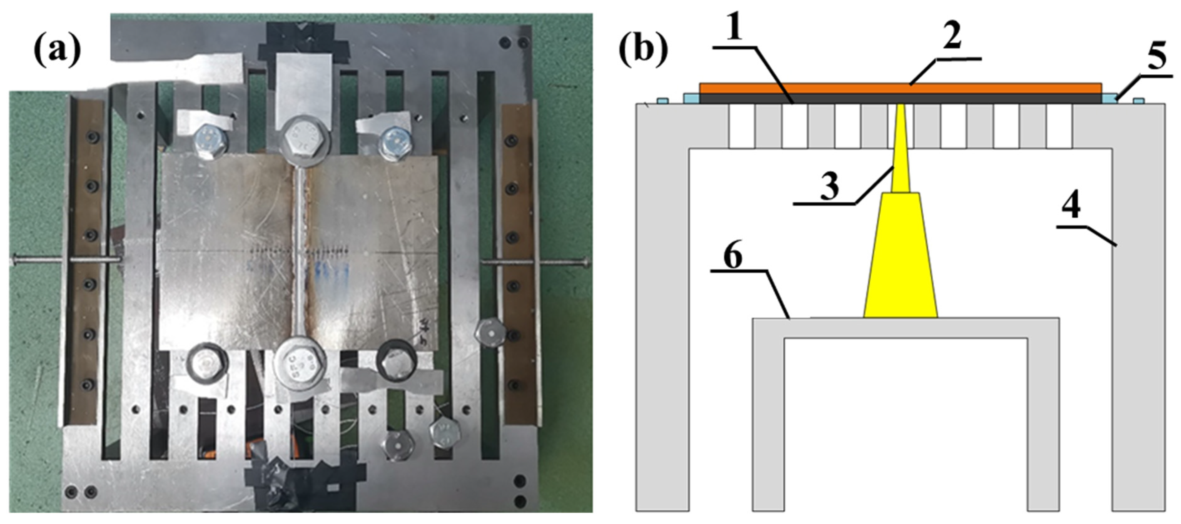
Figure 1. Self-made residual stress control system: (a) Physical drawing of fixture (top view); (b) Fixture diagram (front view).
Metals 13 00018 g001
Figure 2. 316L stainless steel plate sample: (a) Before cutting weld reinforcement; (b) After cutting weld reinforcement.
Metals 13 00018 g002
Figure 3. Principle and equipment of X-ray residual stress measurement: (a) Schematic diagram of the calculation principle of residual stress measurement based on the cosα method; (b) X-ray testing equipment.
Metals 13 00018 g003
Figure 4. Residual stress distribution test location (in mm).
Metals 13 00018 g004
Figure 5. Residual stress distribution of #1 specimen before and after cutting. (a) Front; (b) Back.
Metals 13 00018 g005
Figure 6. Change in average peak residual stress after cutting.
Metals 13 00018 g006
Figure 7. Residual stress distribution of #1 samples before and after treatment. (a) Front; (b) Back.
Metals 13 00018 g007
Figure 8. Change in average peak residual stress after treatment. (a) Front; (b) Back.
Metals 13 00018 g008
Figure 9. Residual stress distribution of #6 samples before and after treatment. (a) Front; (b) Back.
Metals 13 00018 g009
Figure 10. Change in average peak residual stress after treatment. (a) Front; (b) Back.
Metals 13 00018 g010
Figure 11. Residual stress distribution of #7 samples before and after treatment. (a) Front; (b) Back.
Metals 13 00018 g011
Figure 12. Comparison of peak residual stress release effect. (a) Front; (b) Back.
Metals 13 00018 g012
Figure 13. Residual stress distribution of single heat treatment.
Metals 13 00018 g013
Figure 14. Residual stress distribution of single ultrasonic vibration treatment.
Metals 13 00018 g014
Figure 15. KAM diagram of welds before and after regulation. (a) Before regulation; (b) After regulation.
Metals 13 00018 g015
Figure 16. Microstructure of 316L stainless steel. (a) Before regulation; (b) After regulation.
Metals 13 00018 g016
Figure 17. Distribution of grain boundary orientation difference. (a) Before regulation; (b) After regulation.
Metals 13 00018 g017
Table 1. Comparison of advantages and disadvantages.
MethodAdvantageShortcoming
Thermal stress methodUniform stress releaseIt is time-energy consuming. It is only applicable to small and medium-sized structures and the cooling rate requires strict control.
Vibration stress reliefPortable, fast, low costThe excitation frequency is low, meaning that the natural frequency of the sample must be considered, and the residual stress release is uneven.
High-frequency ultrasonic methodPortable, fast, low cost, uniform residual stress release, high-frequency, wider applicationThe residual stress release capacity is limited, meaning that it is not comparable to traditional methods.
Electromagnetic methodPortable and fastThe equipment construction is complex, equipment cost is high, there are strict working environment requirements, and the residual stress release capacity is limited, meaning that it cannot be compared to traditional methods.
Table 2. Chemical compositions of 316L stainless steel plates (mass%).
CSiMnPSNiCrMoFe
0.0190.661.190.0330.00112.1117.412.05Bal.
Table 3. Mechanical properties of 316L stainless steel plates.
MaterialYield Strength (MPa)Tensile Strength (MPa)Elongation (%)
316L≥177≥480≥40
Table 4. Welding parameters of 316L stainless steel.
Electric Current (A)Voltage (V)Gas Flow (L.min−1)Shielding GasWelding Speed
(cm. min−1)
26023.520Ar10
Table 5. Residual stress control parameters.
No.Time (min)Temperature (°C)Amplitude (mm)
#11750.2
#211000.2
#311250.2
#431500.4
#531500.6
#631700.6
#751700.6
Table 6. Peak residual stress changes on the front side of samples #1, #2, and #3.
No.#1-LRS#2-LRS#3-LRS#1-TRS#2-5TRS#3-TRS
After regulation (MPa)281.5260.050.0167.0−24.0143.0
Before regulation (MPa)251.0349.5152.0165.5177.5193.0
Decline rate (%)−12.1525.6167.11−0.91113.5225.91
Release amount (MPa)−30.589.5102.0−1.5201.550.0
Table 7. Peak residual stress changes on the reverse side of samples #1, #2, and #3.
No.#1-LRS#2-LRS#3-LRS#1-TRS#2-TRS#3-TRS
After regulation (MPa)289.5213.0−15.079.0189.529.0
Before regulation (MPa)349.0298.5346.0226.5106.5204.5
Decline rate (%)17.0528.64104.3465.12−77.9385.82
Release amount (MPa)59.585.5361.0147.5−83.0175.5
Table 8. Peak residual stress changes on the front side of samples #4, #5, and #6.
No.#4-LRS#5-LRS#6-LRS#4-TRS#5-TRS#6-TRS
After regulation (MPa)116.57.0239.586.0184.0151.5
Before regulation (MPa)273.0299.5377.0203.0203.0139.5
Decline rate (%)57.3397.6636.4757.649.36−8.60
Release amount (MPa)156.5292.5137.5117.019.0−12.0
Table 9. Peak residual stress changes on the reverse side of samples #4, #5, and #6.
No.#4-LRS#5-LRS#6-LRS#4-TRS#5-TRS#6-TRS
After regulation (MPa)229.0175.5−106.581.553.545.0
Before regulation (MPa)257.0353.5192.0189.091.0131.5
Decline rate (%)10.8950.35155.4756.8841.2165.78
Release amount (MPa)28.0178.0298.5107.537.586.5
Disclaimer/Publisher’s Note: The statements, opinions and data contained in all publications are solely those of the individual author(s) and contributor(s) and not of MDPI and/or the editor(s). MDPI and/or the editor(s) disclaim responsibility for any injury to people or property resulting from any ideas, methods, instructions or products referred to in the content.