Abstract
The corrosion resistance of Cr-containing alloy parts made by additive manufacturing can be significantly improved by a post-treatment of gas-phase-based infusion of concentrated interstitial solute (carbon and nitrogen). We demonstrate this universal approach for the example of low-temperature nitrocarburization by solid-reagent pyrolysis applied to Alloy 22 (UNS N06022) parts made by laser powderbed fusion. We show that the post-treatment improves the crevice-corrosion resistance of these parts, as well as the corrosion resistance of corresponding parts made from wrought Alloy 22 to surpass the maximum crevice corrosion test temperature specified in ASTM G48-D, whereas non-treated samples typically fail well below. Similarly, cyclic potentiodynamic polarization testing (ASTM G61-86) demonstrates that the post-treatment makes the additively manufactured alloy and the wrought alloy more corrosion-resistant than the non-treated wrought alloy.
1. Introduction
AM (additive manufacturing) is a rapidly developing field for rapid prototyping and producing near-net-shape products that are impossible to produce by conventional methods. While there is a large body of active research on the production and properties of AM parts produced by a variety of methods, research into the application of thermo-chemical post-treatments to printed components is still in its infancy [1,2,3]. The goal is to eliminate the deleterious effects that inherent surface defects have on AM parts, especially surface-reaching voids and crevices, as well as segregation of specific atom species to the surface of printed parts. Such defects can adversely affect fracture toughness, fatigue resistance, and corrosion resistance of printed components [4,5,6,7,8]. Surface-reaching voids and crevices constitute stress concentrators, likely sites for crack nucleation. They increase the total surface area of the part. In corrosive environments, they invite pitting corrosion, crevice corrosion, and stress–corrosion cracking. This explains why parts made by AM typically fail earlier in technical applications than parts machined from wrought alloys of the same composition.
Our earlier work on wrought alloys suggests that a highly potent approach for improving surface properties of AM alloys is surface engineering by infusing high concentrations of interstitial solute (carbon or nitrogen) into a subsurface zone with a depth on the micrometer length scale [9]. For alloys containing a significant fraction of Cr, this is possible owing to the strong affinity between Cr and carbon/nitrogen, mutually decreasing their activity coefficients [10]. A temperature window exists within which Cr and other metal atoms (especially Fe and Ni) are practically immobile over the processing time, while carbon and nitrogen—residing in interstitial sites—can still diffuse sufficiently rapidly to technically useful depths [9].
An extensive body of research exists to show that low-temperature infusion of interstitial solute can be applied as a post-treatment to finished alloy parts of any shape and is highly conformal. Variants we have developed include LTC (low-temperature carburization) [9], LTN (low-temperature nitridation) [11], and LTNC (low-temperature nitrocarburization) [12]. The concentration of interstitial carbon or nitrogen in the infused subsurface zone can exceed the respective room-temperature solubility limit by a factor of , corresponding to interstitial atom fractions of order 0.15. The effects of such a concentrated interstitial solution within a subsurface zone with a depth of order 10 μm can quadruple the surface hardness, generate GPa-levels of biaxial compressive stress at the surface, and substantially improve the corrosion resistance to chemical etchants, especially chlorine.
One of the most corrosion-resistant alloys known to date is Alloy 22, UNS N06022, also known as Hastelloy® C-22. Alloy 22 is a high-Ni alloy. It is a prime target for research, development, and application of AM. However, as generally observed for AM alloy parts, AM Alloy 22 parts contain significant densities of intrinsic surface defects, such as voids and crevices into (and below) the surface. These invite crevice corrosion, especially in saltwater, as well as failure by fatigue. Post-processing heat treatments, such as HIP (hot isostatic pressing), can heal subsurface voids to some extent. However, the healing relies on putting the voids under isostatic pressure. Therefore, it does not work for surface-reaching voids.
In this article, we prove the concept of corrosion proofing of AM alloy parts by low-temperature infusion of interstitial solute for the example of Alloy 22 parts made by LPBF (laser powderbed fusion). For post-processing of these parts, we employed our newly developed process of LTNC-SRP (low-temperature nitrocarburization by solidreagent pyrolysis) [12]. The results highlight how this new process can specifically address problems inherent to alloy parts made by AM [1].
2. Materials and Methods
2.1. Raw Materials
To observe and understand the impact of LTNC-SRP on the microstructure and corrosion behavior of Alloy 22, we performed experimental work on wrought and AM Alloy 22. We focus on the effect of the treatment on innate crevices and voids. As figures of merit for corrosion resistance, we compare the CCT (critical crevice temperature) and the CPP (cyclic potentiodynamic polarization) of non-treated- and LTNC-SRP-treated Alloy 22.
As the starting material for wrought Alloy 22, we used round barstock with a diameter of ≈1.6 cm. The composition is shown in Table 1. The material was received in a cold-worked state.

Table 1.
Measured Atom Fractions in Wrought Alloy 22 and Alloy 22 Powder Used for AM.
As the starting material for AM Alloy 22, we used LPBF-printed Alloy 22 coupons. They were fabricated using an AM400 LPBF printer (Renishaw, West Dundee, IL, USA) with an Ar atmosphere. The coupons were cylindrical with a diameter of ≈16 mm and a height of ≈25 mm, sectioned down from bars with an original length of 76 mm. The cylinder axis was perpendicular to the build plate of the AM400. The composition of the Alloy 22 powder used for printing is shown in Table 1. It is known that the structural quality of additively manufactured alloys crucially depends on laser absorptivity (e.g. [13]). In this work, the AM processing parameters were optimized to accomplish a final volume filling >99.90%.
Table 2 describes the raw materials, preparatory heat treatments to the raw materials, the applied LTNC-SRP surface-engineering treatment, as well as sample codes for each state.
Table 2.
Material- and Treatment Codes.
2.2. Raw Material Pre-Treatment
As the wrought Alloy 22 was acquired cold-worked, it needed annealing before sample preparation and testing. We annealed it in air at 1390 K for 3.6 ks, followed by a water quench. The LPBF-printed Alloy 22 samples also needed a pre-treatment, annealing or HIP, to relieve thermal stress from printing before removal from the build plate, to heal non-surface-reaching voids, and to normalize the composition and microstructure. All LPBF Alloy 22 printed bars were stress relieved in air at 1060 K for 21.6 ks before removal from the build plates by wire EDM (electrical discharge machining). One set of printed Alloy 22 bars underwent annealing in air at 1340 K for 7.2 ks, followed by a water quench. The second set of LPBF printed Alloy 22 bars underwent HIP under a pressure of 0.10 GPa in Ar at 1450 K for 14.4 ks.
2.3. Corrosion Coupon Preparation
After initial annealing, the exterior surfaces of all samples were machined to remove the thicker oxide scale that formed during the initial annealing. A layer with a thickness of (0.05…0.10) mm was removed from the surface. (We use “‥” to indicate a continuous range.) The bars were then cut into 6-mm-thick disks and drilled to form a central 6-mm-diameter hole to accommodate the Ti assembly bolts for corrosion testing. All sample flat faces were then ground with SiC papers successively up to P4000 grit, achieving a surface roughness of ≤0.25 μm Ra. The exterior cylinder walls experienced light marring from the sample holder during polishing, but it was determined that this would not affect testing.
2.4. Low-Temperature Nitrocarburization by Solid-Reagent Pyrolysis
Half of each alloy sample group (designations W-A-LTNC, AM-SRA-LTNC, and AM-SRH-LTNC) underwent LTNC-SRP. Before treatment, all samples were cleaned through successive ultrasonic baths of DI (de-ionized) water, isopropanol, and acetone before drying in an oven at 378 K. The samples were treated in a HZS 12/900 tube furnace (Carbolite Gero, Newtown, PA, USA) with an Inconel 600 work tube that has an inner diameter of 55 mm and a length of 1320 mm. To facilitate loading and unloading, the reagent and alloy parts were loaded into fused-silica tubes (inner diameter: 48 mm, length: 150 mm) with loosely fitting end caps with central venting holes that allow gas flow. Within the loading tube, the GuHCl was held in an Al2O3 crucible upstream from the alloy parts to be treated. The reagent mass per alloy surface area was 0.25 kg/m2. These assemblies were heated at ≈ 0.33 K/s to 825 K and held isothermally for 1.8 ks with a continual N2 flow at 1SLPM. Details on how this process was developed can be found in [14].
After cooling under constant N2 flow, samples were extracted and washed of loosely adhered residue through successive ultrasonic baths of DI water, isopropanol, and acetone before drying in an oven at 378 K. Owing to a black residue film remaining on the samples (Figure 2), more aggressive cleaning was required to ensure test validity. An acidified FeCl3 solution (different from the one used for ASTM G48, see below) was used to remove this dark organic residue. Experimentation determined that exposure to this solution can remove the film without causing noticeable damage to the surface. Finally, all samples were washed with DI water and dried as before.
2.5. Critical Crevice-Corrosion Temperature Testing
Crevice-corrosion testing on Alloy 22 samples was conducted according to ASTM G48 Method-D [15]. The test bath solution was an acidified FeCl3 (6% FeCl and 1% HCl by mass, described further in ASTM G48 Method-D). Samples of each alloy material in treated and non-treated state were assembled into the prescribed “Multiple Crevice Assemblies,” as seen in Figure 1, by fixturing each cylindrical coupon sample with Ti bolts and nuts between two TFE-fluorocarbon crevice washers with grooves and plateaus. The assemblies were torqued to 0.28 N·m.
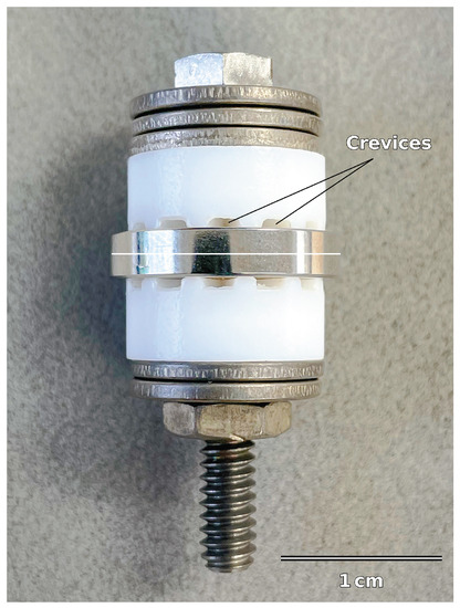
Figure 1.
Multiple crevice assembly with Alloy 22 sample.
The immersion tests were conducted for 259 ks (72 h) at each test temperature, increasing or decreasing the temperature in subsequent tests in order to determine the critical temperature to cause crevice corrosion. Testing occurred at the following temperatures: 343, 348, 353, and 358 K. The maximum test temperature allowed by the solution as specified by the ASTM standard was 358 K, above which the solution may begin to decompose. After testing, samples were washed as before to remove the corrosive solution and corrosion products on the surface. Samples were evaluated for crevice formation and depth measurements with a VHX-7000 light-optical microscope (Keyence Corporation of America, Itasca, IL, USA). The criterion specified to indicate failure in [15] is a local corrosion depth greater than 25 μm.
For metallography and microstructure evaluation, samples were cross-sectioned, mounted in resin, polished, and etched with Kane’s etchant to reveal the corrosion-resistant sub-surface zone infused with interstitial solute (carbon and nitrogen) by the LTNC-SRP process.
2.6. Cyclic Potentiodynamic Polarization
To further probe the corrosion properties of the Alloy 22 sample materials with and without LTNC, we conducted CPP testing. The electrolyte for this test was a 5M CaCl2 aqueous solution that was de-aerated with ultra-high purity N2 before starting each test. The jacketed test cell was connected to a heated water recirculating bath set to 363 K. An SCE (standard calomel electrode) was used for the reference potential. Samples were held in flat PTFE (poly-tetra-fluoro-ethylene) sample holders and pressed against the front washers to exclude electrolyte leakage behind the sample. Before each test, samples were allowed to reach a stable open-circuit potential.
3. Results
3.1. Solid-Reagent Pyrolysis LTNC
After LTNC treatment (as described in Section 2.4), we found the Alloy 22 coupon samples covered by an ≈2 μm thick dark film. As an example, Figure 2 shows a nitrocarburized sample with patches of the dark film surrounding the central bore after exposure to the solution. To ensure the validity of all subsequent tests, treated samples were cleaned of this residue film as described in Section 2. To demonstrate the latter, Figure 3 depicts cross-sectional images of preliminary samples in regions with the dark film (A.0, A.1) and areas with the film removed (B.0, B.1). The way the specimen was prepared, this figure could also reveal microstructure components in the infused subsurface zone. However, the zone appears featureless. Consistent with many similar observations we have made in earlier work on low-temperature carburization [9] and nitrocarburization [12], this observation provides direct evidence for (i) successful infusion of nitrogen and carbon through the alloy surface and (ii) improved corrosion resistance of the infused subsurface zone. From Figure 3, the corrosion resistance is improved to a depth of (5…7) μm for all sample surfaces.
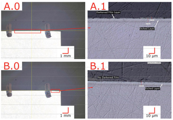
Figure 3.
Cross-section of LTNC-SRP-treated wrought Alloy 22 with an apparent infused-zone depth ≈ 6 μm. (A.0,A.1) Region exhibiting a ≈2 μm thick dark film. (B.0,B.1) Region without dark film.

Figure 2.
Solid-reagent pyrolysis LTNC-treated AM-annealed Alloy 22 sample with patches of dark film remaining after preliminary CCT testing.
Figure 2.
Solid-reagent pyrolysis LTNC-treated AM-annealed Alloy 22 sample with patches of dark film remaining after preliminary CCT testing.

Further evidence for successful infusion of high concentrations of nitrogen and carbon is provided by the X-ray diffractogram in Figure 4. The diffractogram from the non-treated alloy (black) exhibits sharp peaks representing (left to right) {111}, {200}, and {220} planes of the austenite. The diffractogram from the coupon treated by LTNC (red) exhibits the same three peaks. However, the peak centers are shifted toward smaller spatial frequencies q, indicating an expansion of interatomic distances between the metal atoms, i.e. an increase in the lattice parameter. This is a familiar effect, caused by high concentrations of interstitial solute [9].
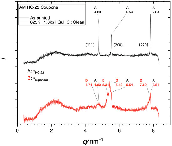
Figure 4.
X-ray diffractogram of GuHCl coupons. To present these data independent of the wavelength of the X-ray source, the diffracted intensity is plotted against the spatial frequency q (not the Bragg angle ). The number labels indicate specific spatial frequencies in nm−1. (A) Black: Diffractogram from the as-received alloy (B) Red: Diffractogram obtained after LTNC.
After CCT testing an LTNC-treated AM-annealed sample, it appeared to have an ≈40 μm-diameter pit on the surface in the area of the red circle in Figure 5, left subfigure. However, further inspection showed this “pit” to actually be an internal void that was revealed by polishing during coupon preparation (Figure 5, right subfigure). Further, the analysis shows that LTNC-SRP works around the subsurface zone of such voids equally well as for planar surface sections. The micrograph indicates an apparent infusion depth ζLOM ≈ 6 μm. (The apparent depth is defined as the depth of the etch-resistant zone that appears in light-optical micrographs. It depends on specific conditions of metallographic etching and does not represent the actual depth distribution of the solute; a sharp infusion depth is incompatible with the laws of diffusion).

Figure 5.
Plan- and cross-sectional view of a sample of AM-SRA-LTNC Alloy 22. In the area of the red circle, the plan view appears to have an ≈40 μm-diameter pit. The cross-section on the right reveals that this actually is an internal void. LTNC-SRP has produced a conformal carbon-rich subsurface zone around the void.
The AM Alloy 22 sample shown in Figure 6 was a cup-shaped alloy piece. This sample was not for crevice-corrosion testing, only to evaluate treatment effects on highly rough and porous as-printed downskin surfaces. The sample was treated similarly to the others shown in this work, except that the GuHCl was deposited as a GuHCl/glycerol paste into the central cavity. The glycerol evaporated and did not seemingly help or hinder treatment effectiveness. The surface of surface-reaching voids (circled in green) shows an interstitial-rich subsurface zone with a depth similar to the depth observed at planar sections of the exterior surface. A conformal subsurface zone of infused interstitial solute also appears on the small peninsular alloy particles seen on the right side of the image. On the other hand, some voids in Figure 6, circled in red, do not show an infused subsurface zone. We conclude that these voids did not make contact with the atmosphere at the time of treatment. In summary, the infused subsurface zone appears conformal and equally developed around all surface sections that are in contact with the atmosphere.
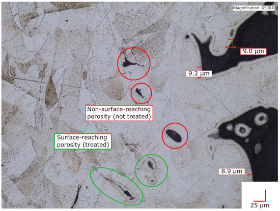
Figure 6.
Cross-sectional image of an LTNC-SRP-treated AM Alloy 22 cup sample. The inner surface of external-surface-reaching voids exhibits a conformal, fully developed subsurface zone of interstitial solute.
3.2. Critical Crevice-Corrosion Temperature Testing
Table 3 contains the results of CCT testing for the six samples of each material–treatment combination. For each sample, the table shows the temperature at which crevice corrosion became strong enough to produce pits deeper than 25 μm. A ≤ sign before the temperature value indicates that the samples failed at or below the specified minimum test temperature. A > sign means that the samples did not fail up to the maximum allowable testing temperature of 358 K.
Table 3.
Critical Crevice-Corrosion Temperature Testing Results for Alloy 22.
As seen in Table 3, all samples of all raw materials (wrought and AM) that were LTNC-SRP-treated passed testing, even at the maximum test temperature. There were no pitting corrosion failures on any of these samples. For example, in Figure 6, there were voids on the AM-SRA-LTNC samples, but the treatment produced a conformal and well-developed interstitial-rich subsurface zone around their inner surface. Therefore, these voids did not cause CCT testing to fail.
Conversely, every single non-treated alloy sample of wrought and AM materials failed at or below the maximum test temperature of 358 K—with most failing significantly below. Figure 7 compares a non-treated sample (left) and an LTNC-treated sample (right) after CCT testing at the maximum test temperature, 358 K. The non-treated, AM-annealed (AM-SRA-X) sample in Figure 7A experienced gross failure, seen as the off-white radial stripes from material that corroded under the crevice washer feet. A detailed analysis of one of these stripes is shown in Figure 8. This image originates from a non-treated AM-SRH-X sample, tested at 343 K. (It developed fewer off-white crevice stripes, apparently because the corrosive attack was less aggressive at this lower temperature.) The overlay in Figure 8 is a height profile measured along a line across one of the off-white radial stripes. Accordingly, corrosive attack removed material down to a depth of 0.25 mm below the original surface and left behind significant surface roughness. Again, most non-treated samples failed well below these temperatures and all had similar corroded appearances.
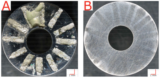
Figure 7.
Plan-view light-optical images after CCT testing at 358 K. (A) AM-SRA-X sample with massive crevice-corrosion failure. (B) AM-SRH-LTNC sample showing no indication of crevice corrosion at the maximum testing temperature.
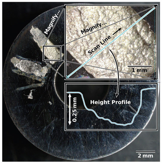
Figure 8.
Height profile measured along a line across one of the off-white radial stripes visible after CCT testing of a non-treated sample (AM-SRH-X) at 343 K.
The LTNC-treated sample in Figure 7B, in contrast, did not corrode in this way. Although the sample was tested at the same high temperature of 358 K as the non-treated sample in Figure 7A, the image shows no indication of even minor crevice-corrosion attack. This appearance is characteristic of all other LTNC-SRP-treated samples.
3.3. Cyclic Potentiodynamic Polarization
Figure 9 shows the CPP results for Alloy 22 samples tested in a CaCl2 electrolyte solution in order to probe pitting behavior through a potential sweep. Figure 9a shows the behavior for non-treated AM Alloy 22. The figure includes two graphs from an AM-SRA-X (annealed) samples and one graph from an AM-SRH-X (HIP-processed) sample. Accordingly, annealing produces variable results. The black curve representing one AM-SRA-X sample reflects typical metastable pitting on the positive sweep, reaching into the transpassive region, and then a negative hysteresis. This sample did not show evidence of pitting after the test. The red graph, however, representing the other AM-SRA-X sample, shows a rapid rise in current at Φ = ΦSCE + 0.5 V. This indicates significant pit formation, which we found confirmed during post-test examination. This sample also has a positive hysteresis, which suggests that it did not repassivate on the sweep toward more negative potentials. The purple graph represents the non-treated HIP-processed sample, AM-SRH-X. This graph indicates slight metastable pitting on the positive sweep, reaching the transpassive region, and a quick subsequent decrease in current density. This sample did not show evidence of pitting after the test. Accordingly, HIP improves the corrosion resistance.
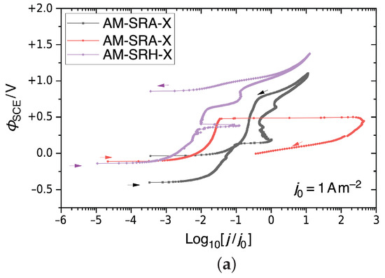
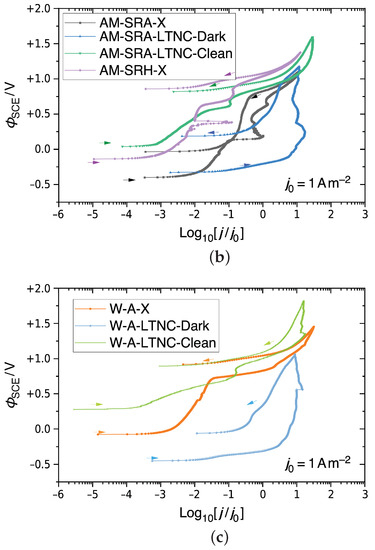
Figure 9.
CPP results for Alloy 22 in 5M CaCl2 at 393 K, shown as semi-logarithmic plots of , the electrostatic relative to an SCE, against the decadic logarithm of the current density j relative to a unit current density. (a) Non-treated AM Alloy 22. (b) Non-treated and LTNC-treated AM Alloy 22. (c) Non-treated and LTNC-treated wrought Alloy 22.
Figure 9b shows the results for two LTNC-treated samples AM-SRA-LTNC. One, AM-SRA-LTNC-Dark, had the dark film remaining on the surface (blue graph), while the other, AM-SRA-LTNC-Clean, had the film cleaned off before testing (green graph). For comparison, the graphs of the two AM-SRA-X samples in Figure 9a are also included here. The blue graph demonstrates that the dark film is not corrosion resistant, as there is a rapid increase in current density throughout the positive potential sweep. The graph eventually reaches the transpassive zone and continues with a negative hysteresis loop. No pitting was observed on this sample after testing, but some of the dark film appeared to be removed. The green graph, representing the analogous sample that was cleaned of its dark film before testing, shows excellent results, similar to the non-treated HIP-processed sample, and no evidence of pitting.
Figure 9c presents corresponding results for wrought Alloy 22 samples. The orange graph represents the wrought-annealed sample W-A-X. It shows minimal metastable pitting but a rapid increase in current density at Φ = ΦSCE + 0.75 V before going transpassive and, finally, a negative hysteresis loop. After the test, the face of this sample exhibited evidence of uniform corrosion. The light-blue graph represents a W-A-LTNC-Dark sample, i.e. with the dark film. The graph confirms that the dark film is not protective and begins to dissolve during the test. The green graph, finally, represents a W-A-LTNC-Clean sample, i.e. dark film cleaned off before testing. This sample went transpassive and produced a negative hysteresis loop. No pitting was observed here after testing.
4. Discussion
4.1. LTNC by Solid-Reagent Pyrolysis
In earlier work [12,14] and in the current work, we have shown that LTNC-SRP can effectively treat a variety of alloys through a diverse range of processing parameters. Our treatment at 825 K for 1.8 ks with GuHCl remote from the alloy pieces produces a uniform infused zone with an apparent depth of ζLOM ≈ 6 μm without sensitization. However, the infused zone has a nitrogen-rich outer sub-zone (dark in light-optical micrographs) and a carbon-rich sub-zone (bright in light-optical micrographs). This is seen, for example, in Figure 6. This is also the reason for the substructure of the shifted peaks observed in the X-ray diffractogram of Figure 4. Generally, the three peaks consist of three different maxima each. This is best observed for the {200} peak (in the middle). On the right-hand side, it exhibits a sharp sub-peak at q = 5.54 nm−1. The position of this sub-peak is identical to that of the {200} peak of the non-treated alloy. The explanation for this sub-peak is that since the interstitial-rich subsurface zone is only ≈5 nm deep, the X-rays penetrated into the non-infused austenite below. The left-most sub-peak represents the nitrogen-rich outer infused subsurface zone, while the sub-peak in the middle represents the carbon-rich subsurface zone below. Accordingly, the infusion of interstitial solute has been accomplished in close analogy to what we have observed in earlier work for many related Cr-bearing wrought alloys, e.g., [10,11,16,17,18,19,20,21,22].
Figure 5 and Figure 6 indicate that the subsurface sub-zones are consistent in thickness, conformal, and uniform also for AM parts with a rough surface and surface-reaching voids. This excellent conformity reflects that the pyrolysis products, including the molecule species that activate the surface and those that provide carbon or nitrogen) arrive at the sample surface as a gas. These gas molecules may adsorb on the alloy surface and diffuse along the surface until they decompose by reaction. The same effect may be achieved by wetting surfaces with condensed pyrolysis products in the case of alloy–reagent contact, although the higher viscosity typical of liquids may compromise the ultimate conformity, e.g., the ability to penetrate microscopic crevices in the surface.
LTNC-SRP enables effective post-treatment of AM alloys for two reasons. Firstly, key to their corrosion resistance of Cr-containing alloys like Alloy 22, is a Cr-rich oxide film that natively forms on the alloy surface and passivates the alloy against further oxidation. An intact oxide film constitutes an effective diffusion barrier to carbon and nitrogen. Before infusion of carbon or nitrogen can take place, therefore, “surface activation” is essential to remove the oxide film or, at least, make it permeable to carbon and nitrogen. The pyrolysis products of the GuHCl reagent we employ in our LTNC-SRP process contain gas molecule species that effectively accomplish this task.
Secondly, the pyrolysis products contain gas molecule species that generate a high activity of carbon and nitrogen at the alloy surface, providing a steep gradient in chemical potential that drives carbon and nitrogen into the alloy. For other alloy systems, the thesis work of Illing [14] has revealed that the pyrolysis product gases HCl and NH3 (ammonia) react with alloy surfaces to remove the passivating oxide film and form a multi-μm-thick reaction layer over the alloy surface. Removing or lowering the diffusion barrier that the oxide film represents to carbon and nitrogen film (or making it transparent) is imperative for carbon and nitrogen transport into the alloy surface. In terms of driving force, chemical potential, or activity, the LTNC-SRP process deposits a condensed layer of carbon and nitrogen source material from the gas, which may provide a higher effective concentration of carbon and nitrogen directly at the surface than would be achievable with a conventional gas-phase process. Lastly, a great benefit of the LTNC co-infusion of carbon and nitrogen (conventional- and solid-reagent pyrolysis based) originates from the fact that interstitial nitrogen increases the chemical potential of interstitial carbon, driving a higher level deeper into the alloy more quickly [23,24,25]. While not unique to the present work’s process, it is an influential facet of surface engineering by infusion of concentrated interstitial solutes that must be considered.
4.2. Corrosion Resistance
Our results show that our post-treatment by LTNC-SRP not only compensates for the inferior crevice corrosion resistance inherent to Alloy 22 made by AM, but actually increases the crevice corrosion resistance beyond that of non-treated parts of wrought Alloy 22, known for their superior corrosion resistance. (The typical CCT for Alloy 22 is 343 K (70 °C) [26].)
Complementing our earlier work, our present work demonstrates that LTNC-SRP can improve corrosion resistance also when applied for shorter times at higher temperature. Previous studies concluded that infusion of interstitial carbon and nitrogen should be conducted at considerably lower temperatures, in the range of (675‥750)K, to avoid carbide and nitride precipitation. The latter would compromise the corrosion resistance by sensitization (lack of Cr activity required to maintain a continuous Cr-rich passivating oxide film on the alloy surface), compromise the fatigue resistance, and may have other deleterious effects. However, the treatment in earlier studies that operated at lower temperature was also carried out for longer processing time (≈72 ks). What we found here is that precipitation of second phases can still be suppressed at higher temperature, such as 825K, as long as the processing time is kept sufficiently short, e.g. 1.8 ks. While second phases do apparently not form, we must still assume that microscopic restructuring of some form takes place to prepare precipitation. It is likely that repeated application of LTNC at 825K for 1.8 ks will cause precipitation to occur. The same consideration holds for repeated conventional low-temperature carburization. In fact, earlier work has shown that excessive repeated application of an industrial low-temperature carburization process eventually causes the intragranular precipitation of carbides [27].
The mean apparent depth of 6 μm to which our LTNC-SRP process infuses carbon and nitrogen into the subsurface of Alloy 22 parts is considerably smaller than that of ≈25 μm obtained with the same processing conditions in AISI-316L (austenitic Fe–Cr–Ni stainless steel containing Mo) and similar alloys. This is expected as Alloy 22 is a Ni-rich alloy. Ni has an (even) lower affinity for carbon and nitrogen than Fe. The results demonstrate that in spite of smaller mean depth of nitrogen and carbon, the LTNC-SRP-treated Alloy 22 parts withstand aggressive crevice-corrosion- and CPP testing without issue. This supports the hypothesis that for improving corrosion resistance, it is the concentration of interstitial solute directly at the alloy surface that is most significant, not the mean penetration depth. This is why the infusion of interstitial solute is equally effective for corrosion-proofing concave surface regions, such as surface-reaching voids, as it is for planar sections of the surface—in spite of the fact that the concentration depth profile decays more rapidly for the former.
A similar observation was made earlier in the context of nitrocarburizing AISI-316L: equivalent benefits to corrosion resistance were apparent on AISI-316L samples that were treated with a similar reagent at the same temperature but shorter duration. For improving mechanical properties, such as fatigue resistance, this may be different.
Recent research has provided a new understanding of the physical principles underlying the improvement of corrosion resistance by concentrated interstitial solute: Based on a proposal by Ernst, Li et al., conducted corrosion research on foils and wires treated by LTC (low-temperature carburization) to the extent of “through” carburization [28]. While past studies suggested that the interstitial carbon (and/or nitrogen) would strengthen the passivating oxide film or retard its breakdown by mechanical stress, Li et al., showed that carbon actually weakens the passive film, but strengthens the bonding within the alloy by forming localized (covalent) bonds with the metal atoms (Fe, Cr, Ni). From other work lead by Ernst and Ren, described in [28,29,30], a result of the localized covalent bonding between the metal atoms and interstitial carbon (and likely nitrogen) is a decrease in electrical conductivity. This decrease was confirmed to be due to a decrease in charge carrier concentration Ne by Hall effect measurements. The concentration Ne (and, therefore, electrical conductivity) decreased because of the localized C–M (carbon–metal) bonding. Aside from the fact that a higher fraction of Ni will somewhat reduce the average strength of C–M bonding, the same physical principle is likely at work to improve the corrosion resistance of the present Alloy 22 samples treated by LTNC-SRP.
The effect of localized C–M- and (currently hypothetical) N–M bond formation on pitting corrosion can be understood as follows. Pitting corrosion requires an anodic reaction (oxidation) of metal species within a pit (e.g. ) and a cathodic (reduction) reaction outside of the pit (e.g. 2H+ + 2e− → H2). As pitting/crevice-corrosion progresses, there is a buildup of metal ions in the local pit electrolyte. The excess positive charge here attracts highly mobile Cl− ions to balance the charge. The increased concentration of metal ions and related complexes leads to hydrolysis of water, which accelerates pitting corrosion [31,32].
The prerequisite for pits to be metastable, i.e. maintain a suitably aggressive solution inside, is that diffusion of metal ions out of the pit is impeded. If the dissolution rate of metal ions is too low, the metastable pit cannot advance to stable pit growth and may repassivate [31]. The localized C–M (or N–M) covalent bonding likely suppresses pitting in at least two ways. First, the localized C–M and N–M bonding decreases the dissolution rate such that a sufficiently high metal ion concentration cannot be achieved in metastable pits or innate surface defects, such as voids. In these cases, dissolved metal ions diffuse out of the feature before stable pit growth can occur. This effect is especially noteworthy because it successfully protects defects, such as the void seen in Figure 5, which are often responsible for the quick and aggressive pitting seen in the non-treated AM-annealed sample (red) in Figure 9a. Additionally, the decreased electrical conductivity may play a role. The decreased conductivity owing to decreased Ne concentration may lead to a lower maximum rate for the reduction reaction outside of the pit. However, this effect will be relatively small in comparison to the bonding effect.
Regarding crevice corrosion, the CCT results of non-treated Alloy 22 in Table 3 show failures well below the maximum test temperature—with most failing around 348 K. Our results track well with those in [26], where failure was occurring around an average temperature of 343 K. Similarly, the ASTM standard for this testing notes the onset of crevice-corrosion attack at temperatures ranging from 323 to 340K [15]. Relative to these results, it is clear that LTNC-SRP is an effective method for preventing crevice-corrosion attack on Alloy 22.
The results of CPP testing in Figure 9 corroborate the results of CCT testing on Alloy 22 that show an increase in crevice corrosion resistance induced by LTNC-SRP. The AM-SRA-X samples show considerable variability in pitting behavior. The variation in CPP and CCT results observed for annealed AM parts likely originates from corresponding variation in the presence of internal voids. How the surface of an annealed AM alloy responds to corrosive attack depends on the stochastic distribution of not fully healed voids and similar defects. Conversely, the cleaned LTNC-SRP-treated parts (AM-SRA-LTNC-Clean and W-A-LTNC-Clean) showed excellent resistance to pitting corrosion. Another interesting finding in these tests is that the dark film is not corrosion resistant and seemingly begins to dissolve immediately, as evidenced by the rapid increase in current density. This suggests that electrochemical means may be effective for removing the film.
5. Conclusions
Our results support the following conclusions.
- AM (additive manufacturing) has great potential, but AM-made alloys with Cr-based corrosion resistance tend to suffer from high surface roughness, surface-reaching voids, and, consequently, increased susceptibility to corrosion, especially crevice corrosion.
- The properties of alloys containing a significant fraction of Cr can be substantially improved by gas-phase-based infusion of concentrated interstitial solute into a micrometer-scale-deep subsurface zone. This can be applied to finished alloy parts as a scalable post-treatment.
- Gas-phase-based infusion of concentrated interstitial solute can effectively treat alloy surfaces with significant roughness. It works perfectly within crevices and surface-reaching voids. The resulting subsurface zone of concentrated interstitial carbon and nitrogen is highly shape-conformal.
- A particularly potent variant of such surface engineering by infusion of concentrated interstitial solute is LTNC-SRP (low-temperature nitrocarburization by solid-reagent pyrolysis). LTNC-SRP excels on conventional processes for the infusion of concentrated interstitial solute under various aspects, including co-infusion of carbon and nitrogen, reduced processing time, and short-term high-temperature processing.
- A subsurface zone infused with carbon and nitrogen can significantly increase the corrosion resistance of Cr-bearing alloys in chlorine/saltwater environments.
- Therefore, LTNC-SRP is a highly potent method for corrosion proofing of a broad spectrum of Cr-containing AM alloys, such as AISI-316L, IN-718, and 2205.
- For Alloy 22 made by AM, as well as for wrought Alloy 22, LTNC-SRP enables significant improvement of crevice-corrosion resistance. This can enable the application of Alloy 22 in extremely corrosive environments.
- LTNC-SRP performed at a relatively high temperature of 825 K on Alloy 22 not only successfully treats alloy surfaces, but also improves the crevice-corrosion resistance relative to non-treated alloy parts (including wrought Alloy 22).
- Gas-phase-based infusion of concentrated interstitial solute, especially LTNC-SRP, likely provides other significant benefits to AM alloy parts beyond corrosion resistance. Owing to the significant increase in hardness and biaxial compressive stress provided by the infused subsurface zone, it may also bolster AM alloy surfaces against wear and high-cycle fatigue by discouraging surface nucleation and opening of cracks during cyclic mechanical loading.
- The LTNC-SRP process can be tailored to produce desired property profiles.
Author Contributions
Conceptualization, M.B., C.I. and F.E.; methodology, M.B., C.I.; validation, C.I., M.B. and F.E.; formal analysis, F.E.; investigation, C.I. and M.B.; resources, M.B.; data curation, C.I., M.B. and F.E.; writing—original draft preparation, C.I. and M.B.; writing—review and editing, F.E.; visualization, F.E., C.I.; supervision, M.B., F.E.; project administration, M.B.; All authors have read and agreed to the published version of the manuscript.
Funding
This research received no external funding.
Institutional Review Board Statement
Not applicable.
Data Availability Statement
Not applicable.
Acknowledgments
We acknowledge internal financial support from Swagelok. We thank P Williams, T Johns, R Edmondson, C Semkow, and J Gress of Swagelok for helpful discussions and for providing specimens.
Conflicts of Interest
C.I. and M.B. are listed on a pending patent related to this article: 171470287–LOW-TEMPERATURE CASE HARDENING OF ADDITIVE MANUFACTURED ARTICLES AND MATERIALS AND TARGETED APPLICATION OF SURFACE MODIFICATION. F.E. has received research funding from Swagelok for other research.
References
- Laleh, M.; Sadeghi, E.; Revilla, R.I.; Chao, Q.; Haghdadi, N.; Hughes, A.E.; Xu, W.; De Graeve, I.; Qian, M.; Gibson, I.; et al. Heat treatment for metal additive manufacturing. Prog. Mater. Sci. 2023, 133, 101051. [Google Scholar] [CrossRef]
- Funch, C.V.; Somlo, K.; Christiansen, T.L.; Somers, M.A. Thermochemical post-processing of additively manufactured austenitic stainless steel. Surf. Coatings Technol. 2022, 441, 128495. [Google Scholar] [CrossRef]
- Montanari, R.; Lanzutti, A.; Richetta, M.; Tursunbaev, J.; Vaglio, E.; Varone, A.; Verona, C. Plasma Carburizing of Laser Powder Bed Fusion Manufactured 316 L Steel for Enhancing the Surface Hardness. Coatings 2022, 12, 258. [Google Scholar] [CrossRef]
- Trelewicz, J.R.; Halada, G.P.; Donaldson, O.K.; Manogharan, G. Microstructure and corrosion resistance of laser additively manufactured 316L stainless steel. Jom 2016, 68, 850–859. [Google Scholar] [CrossRef]
- Sander, G.; Tan, J.; Balan, P.; Gharbi, O.; Feenstra, D.; Singer, L.; Thomas, S.; Kelly, R.; Scully, J.R.; Birbilis, N. Corrosion of additively manufactured alloys: A review. Corrosion 2018, 74, 1318–1350. [Google Scholar] [CrossRef]
- Bajaj, P.; Hariharan, A.; Kini, A.; Kürnsteiner, P.; Raabe, D.; Jägle, E.A. Steels in additive manufacturing: A review of their microstructure and properties. Mater. Sci. Eng. A 2020, 772, 138633. [Google Scholar] [CrossRef]
- Sander, G.; Thomas, S.; Cruz, V.; Jurg, M.; Birbilis, N.; Gao, X.; Brameld, M.; Hutchinson, C. On the corrosion and metastable pitting characteristics of 316L stainless steel produced by selective laser melting. J. Electrochem. Soc. 2017, 164, C250. [Google Scholar] [CrossRef]
- Ziętala, M.; Durejko, T.; Polański, M.; Kunce, I.; Płociński, T.; Zieliński, W.; Łazińska, M.; Stępniowski, W.; Czujko, T.; Kurzydłowski, K.J.; et al. The microstructure, mechanical properties and corrosion resistance of 316 L stainless steel fabricated using laser engineered net shaping. Mater. Sci. Eng. A 2016, 677, 1–10. [Google Scholar] [CrossRef]
- Collins, S.R.; Williams, P.C.; Marx, S.V.; Heuer, A.H.; Ernst, F.; Kahn, H. Low-Temperature Carburization of Austenitic Stainless Steels. In ASM Handbook: Vol. 4D, Heat Treating of Irons and Steels; Dossett, J., Totten, G., Eds.; ASM International: Materials Park, OH, USA, 2014; Volume 4, pp. 451–460. [Google Scholar]
- Michal, G.M.; Ernst, F.; Kahn, H.; Cao, Y.; Oba, F.; Agarwal, N.; Heuer, A.H. Colossal Carbon Supersaturation due to Paraequilibrium Carburization: Stainless Steels with Greatly Improved Mechanical Properties. Acta Mater. 2006, 54, 1597–1606. [Google Scholar] [CrossRef]
- Wu, D.; Ge, Y.; Kahn, H.; Ernst, F.; Heuer, A.H. Diffusion Profiles after Nitrocarburizing Austenitic Stainless Steel. Surf. Coatings Technol. 2016, 279, 180–185. [Google Scholar] [CrossRef]
- Illing, C.; Ren, Z.; Agaponova, A.; Heuer, A.; Ernst, F. Rapid Alloy Surface Engineering through Closed-Vessel Reagent Pyrolysis. Metals 2021, 11, 1764. [Google Scholar] [CrossRef]
- Khorasani, M.; Ghasemi, A.; Leary, M.; Sharabian, E.; Cordova, L.; Gibson, I.; Downing, D.; Bateman, S.; Brandt, M.; Rolfe, B. The effect of absorption ratio on meltpool features in laser-based powder bed fusion of IN718. Opt. Laser Technol. 2022, 153, 108263. [Google Scholar] [CrossRef]
- Illing, C.A. Alloy Surface Engineering by Solid-Reagent Pyrolysis. Ph.D. Thesis, Case Western Reserve University, Cleveland, OH, USA, 2022. [Google Scholar]
- G01 Committee. Test Methods for Pitting and Crevice Corrosion Resistance of Stainless Steels and Related Alloys by Use of Ferric Chloride Solution; Technical Report; ASTM International: Materials Park, OH, USA, 2020. [Google Scholar] [CrossRef]
- Ren, Z.; Heuer, A.H.; Ernst, F. Ultrahigh-strength AISI-316 austenitic stainless steel foils through concentrated interstitial carbon. Acta Mater. 2019, 167, 231–240. [Google Scholar] [CrossRef]
- Ren, Z.; Eppell, S.; Collins, S.; Ernst, F. Co–Cr–Mo alloys: Improved wear resistance through low-temperature gas-phase nitro-carburization. Surf. Coatings Technol. 2019, 378, 124943. [Google Scholar] [CrossRef]
- Li, Z.; Illing, C.; Heuer, A.H.; Ernst, F. Low-Temperature Carburization of AL-6XN Enabled by Provisional Passivation. Metals 2018, 8, 997. [Google Scholar] [CrossRef]
- Dalton, J.C.; Ernst, F.; Heuer, A.H. Low-Temperature Nitridation of 2205 Duplex Stainless Steel. Metall. Mater. Trans. A 2019, 51, 608–617. [Google Scholar] [CrossRef]
- Wu, D.; Kahn, H.; Michal, G.; Ernst, F.; Heuer, A. Ferromagnetism in Interstitially Hardened Austenitic Stainless Steel Induced by Low-Temperature Gas-Phase Nitriding. Scr. Mater. 2011, 65, 1089–1092. [Google Scholar] [CrossRef]
- Sharghi-Moshtaghin, R.; Ge, Y.; Kahn, H.; Gu, X.; Martin, F.; Natishan, P.; Rayne, R.; Michal, G.; Ernst, F.; Heuer, A.H. Low-Temperature Carburization of the Ni-base Superalloy IN718: Improvements in Surface Hardness and Crevice Corrosion Resistance. Metall. Mater. Trans. 2010, 41, 2022–2032. [Google Scholar] [CrossRef]
- Michal, G.M.; Gu, X.; Jennings, W.D.; Kahn, H.; Ernst, F.; Heuer, A.H. Paraequilibrium Carburization of Duplex and Ferritic Stainless Steels. Metall. Mater. Trans. A 2009, 40, 1781–1790. [Google Scholar] [CrossRef]
- Gu, X. Numerical Simulations of Concentration-Depth Profiles of Carbon and Nitrogen in Austenitic Stainless Steel Based upon Highly Concentration Dependent Diffusivities. Ph.D. Thesis, Case Western Reserve University, Cleveland, OH, USA, 2011. [Google Scholar]
- Gu, X.; Michal, G.M.; Ernst, F.; Kahn, H.; Heuer, A.H. Numerical Simulations of Carbon and Nitrogen Composition-Depth Profiles in Nitrocarburized Austenitic Stainless Steels. Metall. Mater. Trans. A 2014, 45, 4268–4279. [Google Scholar] [CrossRef]
- Gu, X.; Michal, G.M.; Ernst, F.; Kahn, H.; Heuer, A.H. Concentration-Dependent Carbon Diffusivity in Austenite. Metall. Mater. Trans. A 2014, 45, 3790–3799. [Google Scholar] [CrossRef]
- Eisinger, N.C.; Shoemaker, L.E. An Explanation of Corrosion Acceptance Tests and Their Applicability to Field Use. In Proceedings of the Corrosion 2007, Nashville, TN, USA, 11–15 March 2007. NACE-07202. [Google Scholar]
- Ernst, F.; Cao, Y.; Michal, G. Carbides in low-temperature-carburized stainless steels. Acta Mater. 2004, 52, 1469–1477. [Google Scholar] [CrossRef]
- Li, T.; Chien, S.C.; Ren, Z.; Windl, W.; Ernst, F.; Frankel, G.S. Understanding the efficacy of concentrated interstitial carbon in enhancing the pitting corrosion resistance of stainless steel. Acta Mater. 2021, 221, 117433. [Google Scholar] [CrossRef]
- Ren, Z. Intrinsic Properties of “Case” and Potential Biomedical Applications. Ph.D. Thesis, Case Western Reserve University, Cleveland, OH, USA, 2019. [Google Scholar]
- Ren, Z.; Ernst, F. Electronic Impact of Concentrated Interstitial Carbon on Physical Properties of AISI-316 Austenitic Stainless Steel. Acta Mater. 2019, 173, 96–105. [Google Scholar] [CrossRef]
- Pistorius, P.C.; Burstein, G.T. Metastable Pitting Corrosion of Stainless Steel and the Transition to Stability. Philos. Trans. Phys. Sci. Eng. 1992, 341, 531–559. [Google Scholar]
- Davis, J.R. Corrosion: Understanding the Basics; ASM International: Materials Park, OH, USA, 2000. [Google Scholar]


Disclaimer/Publisher’s Note: The statements, opinions and data contained in all publications are solely those of the individual author(s) and contributor(s) and not of MDPI and/or the editor(s). MDPI and/or the editor(s) disclaim responsibility for any injury to people or property resulting from any ideas, methods, instructions or products referred to in the content. |
© 2023 by the authors. Licensee MDPI, Basel, Switzerland. This article is an open access article distributed under the terms and conditions of the Creative Commons Attribution (CC BY) license (https://creativecommons.org/licenses/by/4.0/).