Abstract
The technology for producing artificial rutile by the reduction-rusting method has the advantages of high product quality and less slag. A computational fluid dynamics (CFD) method is used to simulate the solid-liquid suspension and gas-liquid dispersion characteristics in the stirred corrosion reactor. The results show that the maximum volume fraction difference of the solid phase in the reactor with an upward-lifting impeller is 0.02, and for the downforce type, it is 0.04. When the stirring speed is increased from 100 rpm to 150 rpm, the radial dispersion area of the gas phase is increased; after the six-inclined-blade disk turbine is selected as the lower impeller, the proportion of bubbles with a diameter less than 0.004 m in the reactor is increased from 26% to 45%. The content of metallic iron in the product of the corrosion reaction is 1.67% in the stirred reactor with a six-inclined-blade disk turbine as the lower impeller.
1. Introduction
The reduction-rusting method is an important method to produce artificial rutile. The reaction time of the rusting process is long (more than 10 h) and the efficiency is low. The rusting process is a typical gas-liquid-solid three-phase system [1] and the Reaction principle is as follows:
Oxidation of ferrous ions:
Stirring is a common means to strengthen the heterogeneous reaction process. By stirring, the phenomena of uneven reaction and local overheating caused by uneven materials can be improved. Reasonable stirring can not only improve the reaction processes but also save energy consumption. According to the investigation and statistics of the non-ferrous metallurgy department, stirring energy consumption accounts for more than 50% of the total energy consumption in many wet workshop operations [2]. The mixing effect in the stirred reactor depends to a great extent on the structural parameters, operating parameters and mixing characteristics of the stirrer [3]. Therefore, optimizing the structure and operating parameters of the multiphase stirred reactor is beneficial to enhance the mixing performance, thus improving the gas-liquid dispersion uniformity and solid-liquid suspension effect, reducing the reaction time and energy consumption. However, in the stirring process, due to the differences in the material system, stirring speed, impeller type and other structures or operating parameters, the power consumption, phase distribution and flow structure mode of the stirring system will also be different [4,5,6], so it is necessary to study the phase distribution characteristics of reactors with different parameters.
At present, scholars have conducted a lot of research on the flow field information of aerated agitated reactors. Vincenzo Cappello, et al. [7] carried out experiments to obtain the volumetric mass transfer coefficient and the global gas holdup in a biological aeration reactor; Diego Mesa, et al. [8] discussed the effect of two impellers, with and without a stator, as well as the effect of air flowrate, impeller speed and surfactant concentration on bubble size in a laboratory-scale aerated stirred tank; Francesco Maluta, et al. [9] used two-fluids RANS to predict gas cavities, power consumption, mixing time and oxygen transfer rate in an aerated fermenter scale-down stirred with multiple impellers; Kalaga D V, et al. [10] studied the flow characteristics of different scale bioreactors through experiments, and it is found that compared with the gas column with a diameter of 0.3 m, the influence of the gas injection position in the gas column with a diameter of 0.1 m on the average gas phase volume fraction and the axial gas fraction distribution is much smaller; Panneerselvam R, et al. [11] used double Euler and Standard k-ε Model to simulate the gas-liquid-solid three-phase contact stirrer, compared with the experimental data, which verified the axial and radial velocity fields in the solid-liquid and gas-liquid systems and simulated the critical stirring speed of the three-phase stirring. Additionally, many studies [12,13,14] have been conducted to estimate bubble size in stirred reactors, mainly in water and at low gas velocity.
Most of the above studies focus on bioreactors. The gas-liquid-solid system is based on a reduction-rusting process in this paper. Some experiments to obtain the characteristic of solid suspension and gas distribution in smaller tanks with diameters of 400 mm have been conducted [15,16]. In this work, the concentration field and bubble size distribution are studied in industrial-size corrosion reactors with diameters of 2500 mm and 3500 mm. By comparing the characteristics of solid volume distribution and turbulent kinetic energy distribution, the scale-up criteria for the corrosion reactors were selected. The above provides a theoretical basis for the scale-up design of the three-phase refactor for the corrosion process of reduced ilmenite.
2. Materials and Methods
2.1. Numerical Method
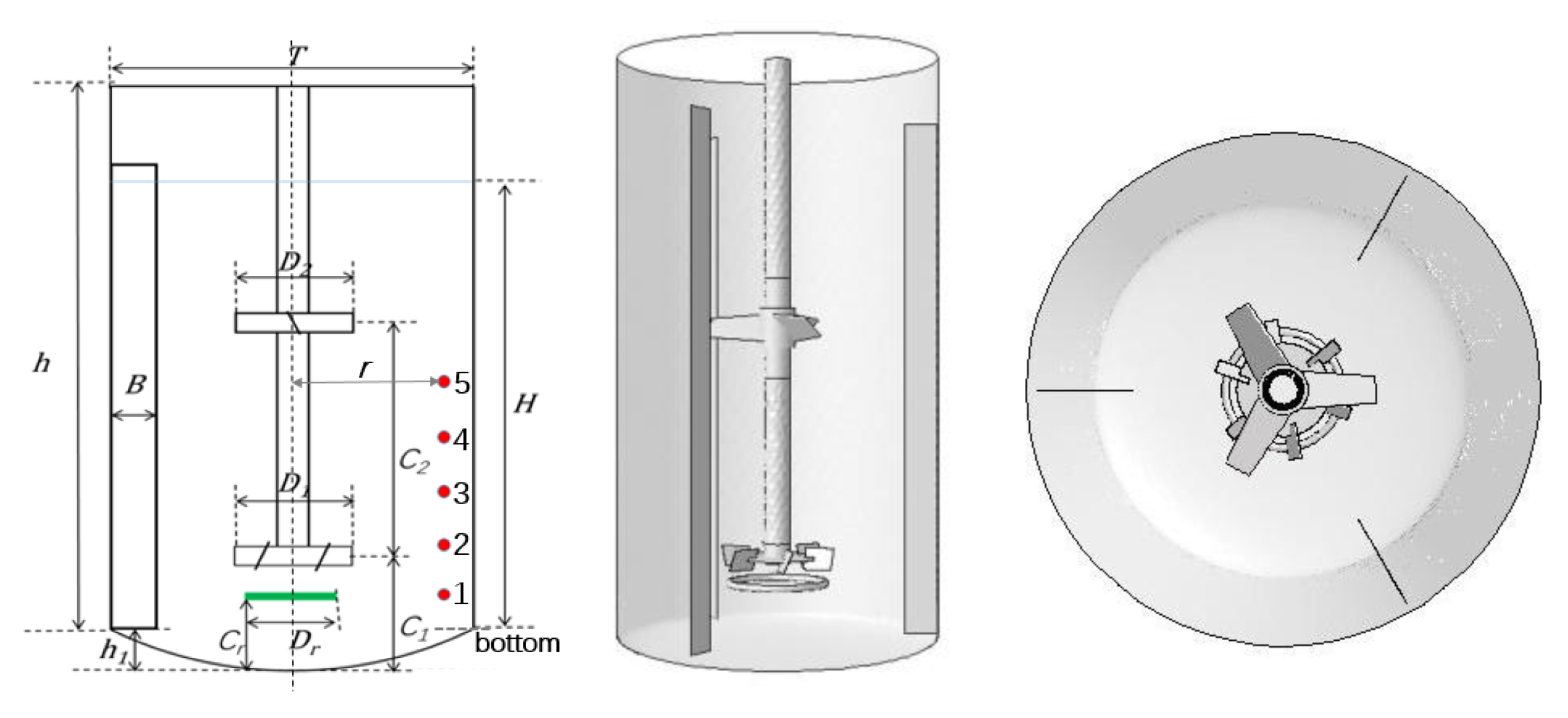
In this work, Mixsim (V2.0.2, FLUENT, Lebanon, NH, USA) and Fluent (2020R2, ANSYS, Canonsburg, PA, USA) are used. The overall structure of the reactor is shown in Figure 1.
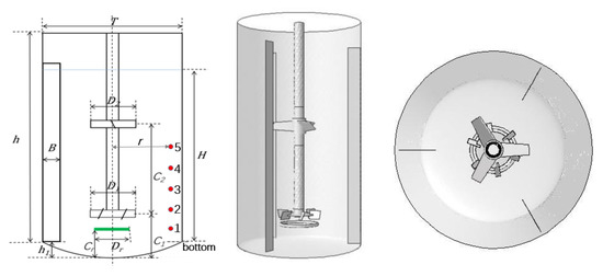
Figure 1.
Geometric Structure of Industrial Scale Stirred Reactor.
The reactor is a cylindrical cylinder with a diameter of 2500 mm, the height of the reactor is 4500 mm, and the bottom of the reactor is an oval head with a height of 200 mm. In order to eliminate the vortex phenomenon, three baffles are uniformly distributed on the inner wall of the stirred reactor, and the specific sizes are shown in Table 1. The dependencies between the main geometrical parameters of the mixer are as below: h/T = 1.8, B/T = 0.1, D1/T = 0.42, D2/T = 0.36, C1/T = 0.32, and C2/T = 0.64. Table 2 shows the type of double-layer impeller.

Table 1.
Geometric parameters of industrial scale mixing stirred reactor.
Table 2.
Type of double-layer impeller.
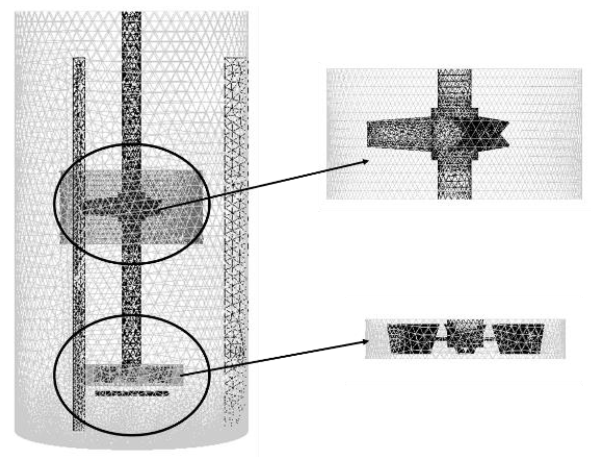
Tetrahedral grids are highly body-fitting and friendly to irregular geometry, so unstructured tetrahedral grids are used here as shown in Figure 2. The whole reactor is grouped into two following categories: the area wrapping the blades of the dual layer stirring impeller is called the blade rotating area, and the rest is called the static area.

Figure 2.
Schematic Diagram of Grid Division of Industrial Scale Stirred Reactor.
2.2. Physical Properties
The reaction involves three phases of gas (air), liquid (Aqueous solution containing 1.5% HCl) and solid (Reduced ilmenite, which main components are TiO2 and Fe), of which the physical parameters of each phase are shown in Table 3.
Table 3.
Three-phase physical properties.
The simulation process of stirring adopts the Multiple Reference Frame method [17] (MRF), the key of which is to divide the space in the reactor into the dynamic region wrapping the blades and other (static) regions. The physical parameters of the two regions are calculated in different coordinate systems, and the calculation data are transmitted through the region boundary. The standard model of the two-equation turbulence model is used to describe the turbulent flow. For the description of multiphase flow, the Euler–Euler “three-fluid” model is selected, and the Schiller–Naumann model is adopted for the drag force model between three phases [18]. The population balance model (PBM) was used to predict the size and distribution of a large number of bubbles. Furthermore, the standard wall function is used to deal with the near-wall region of the inner wall, blade, stirring shaft and other wall boundaries of the reactor, and the Phase Coupled Simple algorithm is used to realize the pressure-velocity coupling problem.
Considering the complexity of the reaction process, the simulation process is simplified to some extent. The process does not consider heat absorption and release in the reaction process, so the energy model is not involved. For the flow of each phase in the stirred reactor, two basic equations of mass conservation (continuity equation) and momentum conservation (Navier–Stokes equation) must be satisfied.
Continuity equation:
Navier–Stokes equation:
And satisfies:
Here, is the volume ratio of phase i, is the density(kg/m3) of phase i, is the instantaneous velocity(m/s) of phase i, p is the common pressure (Pa) of each phase, is the stress tensor (N/m2), and is the momentum transfer phase, which originates from the interaction force between each phase.
represents each phase in the reactor (s is the solid phase, l is the liquid phase, and g is the gas phase). Each phase is treated as a continuous phase permeating each other, but the volume of each phase in the shared space unit is not occupied by other phases, which means the volume fraction sum of each phase is 1.
3. Results
3.1. Model Validation
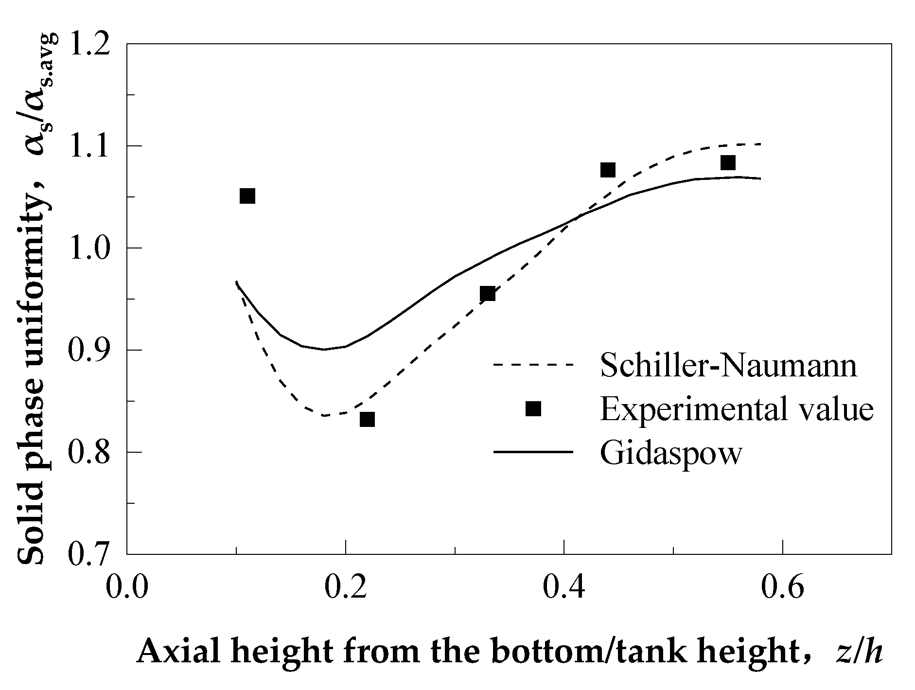
In order to select an appropriate mathematical model, the particle suspension uniformity and the average bubble diameter were simulated and compared with the experimental data [18]. The detection positions of solid phase volume fraction are shown in Figure 1 as points 1 to 5, where r/T = 0.75 and The ratio of the distance between each point and the bottom to the height h is 0.11, 0.22, 0.33, 0.44 and 0.55, respectively. The transient calculation method is applied in the numerical simulation, the final results are processed by time average to reflect the average trend of the speed change. The comparison results are shown in Figure 3. It can be found that the prediction of the solid phase uniformity in the reactor by the two drag force models is in good agreement with the experimental results. There are some errors in the calculation results near the impeller; the reason may be that the boundary conditions on the wall of the impellor blade are relatively complex and the turbulence intensity at this position is too high. The maximum error of the Gidaspow model is 11.1%, and the average error is 4.952%, while the maximum error of the Schiller–Naumann model is 8.68%, and the average error is 3.2%. So, the Schiller–Naumann model is selected to express the phase drag force.
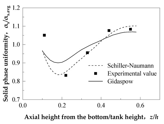
Figure 3.
Comparison of experimental value of uniformity axial distribution with CFD value.
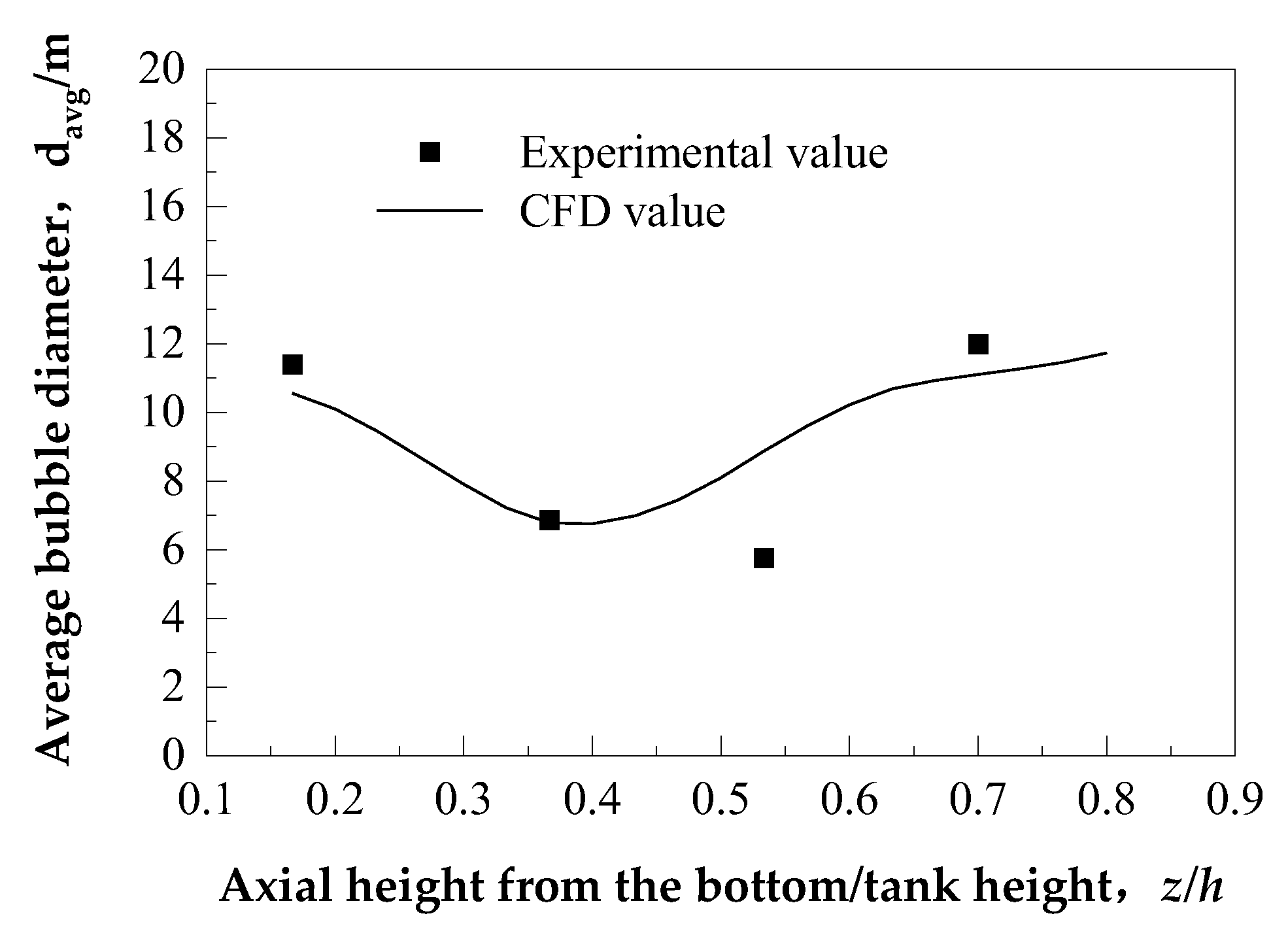
For the simulation verification of gas-liquid flow, the gas rate, the superficial gas velocity and the stirring speed are 2 m3/h, 0.0044 m/s and 200 rpm, respectively, according to [18]. The comparison results are shown in Figure 4. In the process of rising from the bottom of the reactor, the bubbles are broken into small bubbles after stirring, and then coalesce again to become larger diameter bubbles, so, the simulation can better describe the experimental results.
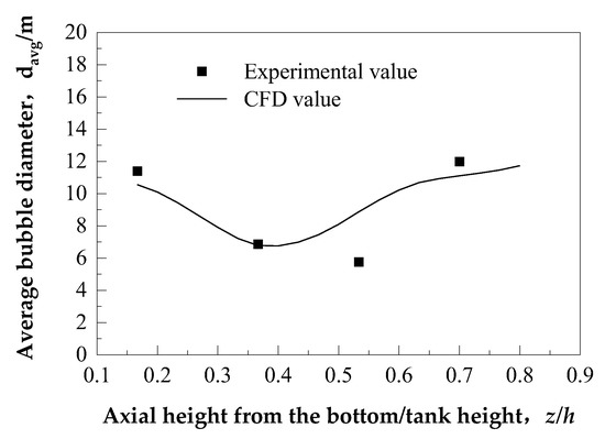
Figure 4.
Comparison of experimental value and CFD value of axial local bubble diameter.
3.2. The Flow under Different Stirring Speed and Stirring Direction
Looking down from the top of the reactor, the anticlockwise rotation of the stirring shaft and clockwise rotation (there is a “-” sign before the rotation speed) is defined. Select scheme A, when the stirring impeller rotates at 100 rpm, 150 rpm, −100 rpm, and −150 rpm, respectively, to explore the influence of stirring speed and stirring direction on the flow properties of each phase in the reactor.
According to the detection position shown in Table 4, the solid concentration at the axial and radial positions in the reactor is detected; horizontal planes with different heights in the axial direction and detection lines with different distances from the axis in the radial direction are adopted, and the solid volume fraction values were obtained at the detection positions.
Table 4.
Position of monitoring section and monitoring line (m).
Figure 5 shows the solid phase volume fraction at different detection positions. As the blades of the axial flow impeller have a certain inclination angle, the fluid in the reactor is forced to move axially when rotate [19,20]. However, when the rotation direction is different, there are two effects of “lifting” and “pressing” on the fluid at the bottom of the reactor due to the different force component directions. When the stirring direction is reversed, the upper and lower double-layer stirring impellers are the “downfore type”. In the figure, the axial solid content decreases at the position of the stirring impellers (Z = 1, Z = 2.5). The difference in the solid volume fraction between the bottom and top of the stirring reactor is large, with the maximum difference approaching 0.04. The distribution of solid particles in the reactor is not uniform, indicating that there is material accumulation at the bottom of the reactor. When the stirring speed rises to 150 rpm, the average solid volume fraction difference on the monitoring surface has little change, while the solid volume fraction difference between the top and bottom of the stirred tank further increases. The solid distribution at different positions in the radial direction is relatively uniform, and the maximum difference in the solid volume fraction is about 0.02.
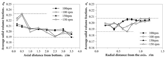
Figure 5.
The solid volume frame in different positions.
Under the condition of positive stirring direction, the distribution trend of solids is relatively consistent, and the maximum volume fraction difference between the top and bottom solids is 0.02, which indicates that the lifting stirring impeller can roll up the solid particles at the bottom of the reactor and is beneficial to reduce the accumulation of materials at the bottom. When the stirring speed is increased to 150 rpm, the difference of solid volume fraction in the monitoring section has little change, and it is of little significance for the solid-liquid suspension effect to continue to increase the stirring speed. The whole body is uniform at different positions in the radial direction, and the maximum difference of the solid volume fraction is about 0.015.
As shown in Figure 6, different stirring directions have significant effects on gas-liquid dispersion. When the stirring shaft rotates in the opposite direction, there is better gas dispersion. Under forward stirring, the gas is more concentrated near the stirring shaft. Regardless of forward or reverse rotation, the dispersion of gas is both better at a stirring speed of 150 rpm than that at 100 rpm. Considering the energy consumption, the speed taken in the later research is 125 rpm.
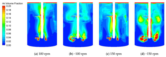
Figure 6.
Gas distribution under different stirring speeds.
3.3. The Flow under Different Impeller Types
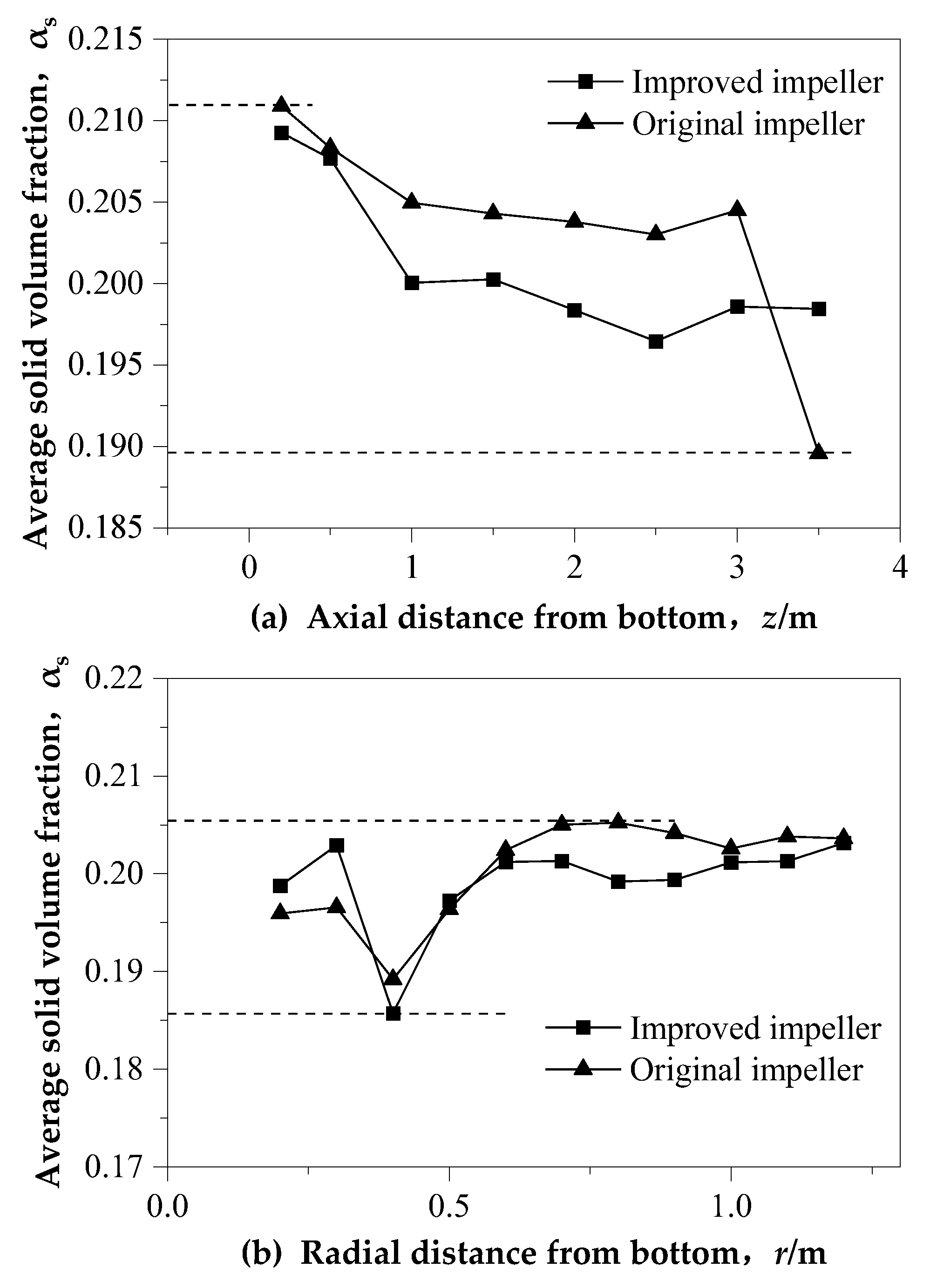
Figure 7 shows the axial and radial solid volume fraction in that reactor before and after the modification of the impeller. After the improvement (shown in Table 2), the axial solid volume fraction difference of the solid phase becomes smaller. The maximum difference is reduced from 0.02 to 0.015. The main change is that there is no sudden drop of solid content near the liquid level after the improvement.
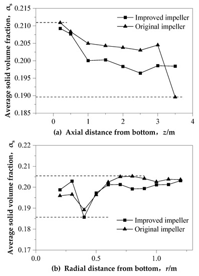
Figure 7.
The value of solid volume frame of different impeller types under 125 rpm.
The overall trend of radial solid content with different impellers is close, and the solid volume fraction decreases at x = 0.4 m, which may be due to the rapid diffusion of gas under the shear action of the stirring impeller, which makes the solid concentration decrease here.
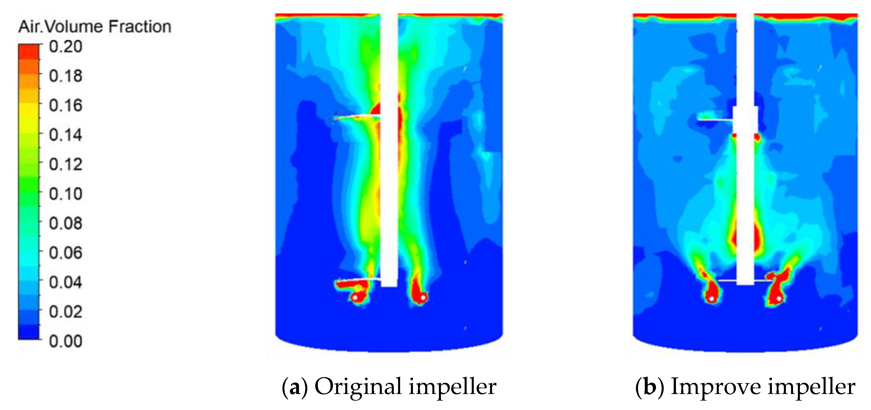
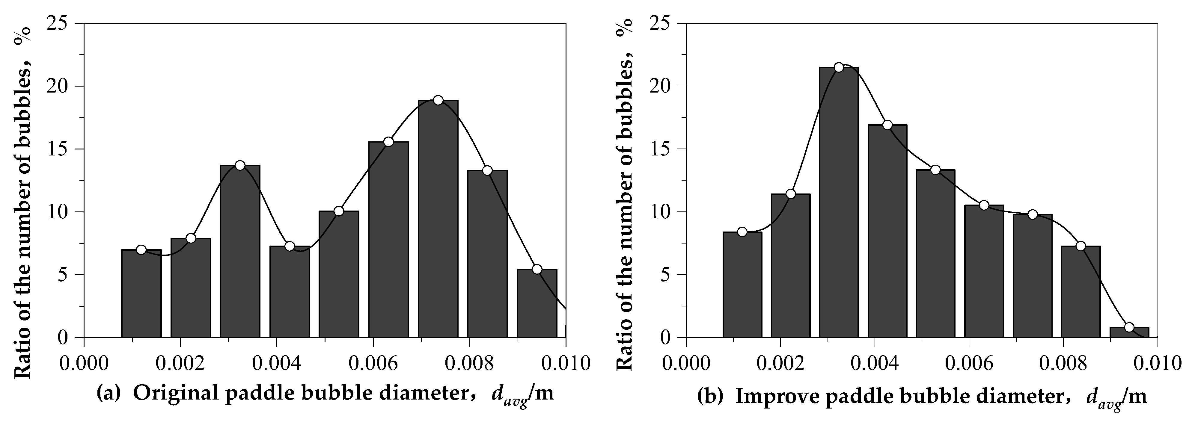
As can be found from Figure 8 and Figure 9, the improved impeller combination makes the gas phase disperse better in the reactor, the radial diffusion ranges larger, and the number of small bubbles accounts for more. The proportion of bubbles with a diameter less than 0.004 m increases from 26% to 45%. In addition, through the graphs of the two sets of data, it can be found that the maximum peak value of the bubble diameter is reduced from 0.007 to 0.004 after the improvement, which indicates that the six-inclined blade disc turbine propeller is beneficial to the gas-liquid dispersion, and the bubble disintegration effect is also better than the three-wide blade propeller.
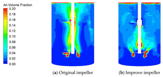
Figure 8.
Gas distribution under different impeller type combinations under 125 rpm.
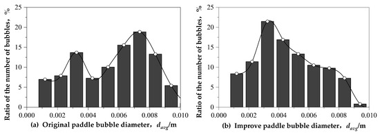
Figure 9.
Bubble diameter distribution under different impeller type combinations under 125 rpm.
3.4. Corrosion Reaction Results
According to the above simulation results, the stirred reactor was selected with an upward-lifting agitator as the upper impeller and a six-inclined-blade disk turbine as the lower impeller. The reduced ilmenite is used as raw material (as Table 5), the oxygen flow rate is 0.6 m3/h, the liquid-solid ratio is 4:1, room temperature, and the reaction time is 2 h for corrosion reaction. The corrosion system is a mixture of 2% ammonium chloride and 3% hydrochloric acid.
Table 5.
Position of monitoring section and monitoring line.
Specific corrosion reaction results are shown in Table 6.
Table 6.
Results of corrosion reaction.
Generally, the corrosion effect is based on the content of metal iron in the product, and about 1% is regarded as the end of the reaction, indicating that the selected mixing blade structure is appropriate.
4. Discussion
4.1. Influence of Stirring Speed and Stirring Direction on the Flow
Theoretically, when the rising velocity balances the settling velocity of solid particles [21] or the turbulent vortex transfers energy to the particle to balance force [22], only in this way can the solid particles remain suspended. The axial flow of the “ up-pumping “ impeller drives the bottom particles in the reactor to suspend, while the “down pumping” impeller produces secondary circulation flow that collides with the wall to carry the particles into suspension, which has a certain energy dissipation; the suspension effect is weaker than the former.
Gas is less likely to escape from the liquid surface due to the downward blocking effect in the whole reactor with a “down pumping” impeller, and the radial diffusion effect of the gas is better at the same stirring speed. When the stirring speed is increased, the radial diffusion range of the gas is larger. Paradoxically, the “up pumping” impeller is beneficial to solid suspension, but its upward lifting force also accelerates the rise of the bottom gas. The bubbles rise rapidly along the axis, which shortens the residence time of the gas in the reactor and reduces the contact area between the gas and other phases in a disguised form. Therefore, the key to ensuring solid suspension and gas dispersion is to select an appropriate impeller for a gas-liquid-solid three-phase reaction and achieve the effect of lifting and pressing at the same time.
4.2. Influence of Different Combined Impeller Types on the Flow
When the impeller shear force is small, the dispersion ability of the gas is weakened, resulting in the easy escape of the gas. At the same time, the solid particles gather under the bubble layer, and the axial distribution of the solid is also uneven.
In order to optimize the three-phase reactor, the blades of the double-layer impellers should be different. The lower impeller is the “lifting type” and the upper impeller is the “pressing type”. The lower impeller can roll up the bottom solid particles in the reactor, and the upper impeller can also prevent the escape of gas, so as to make the three-phase mix more fully. In order to further enhance the radial diffusion of bubbles, the lower impeller is changed to an inclined blade disc turbine impeller, which can reduce the bubbles escaping directly upward along the mixing shaft.
4.3. Amplification Criterion for Corrosion Reactor
Turbulent kinetic energy is an important index to measure the mixing ability and also it is important for a corrosion reactor. The turbulent kinetic energy distribution shows that the flow effect at 90 rpm in a 3500 mm diameter reactor is similar to that at 125 rpm in a 2500 mm diameter reactor. The relationship between the two speeds conforms to the amplification criterion of the equal linear velocity of the blade end. The same linear velocity at the blade end is also a common amplification criterion for stirred reactors.
5. Conclusions
Taking the gas-liquid-solid three-phase stirred reactor for the corrosion process of reduced ilmenite as the research object, the three-phase distribution is simulated by computational fluid dynamics software. By comparing the experimental data of gas-liquid dispersion and solid-liquid suspension, a relatively suitable Schiller–Naumann model is selected to describe the interphase drag force. The stirring speed, stirring direction and phase distribution characteristics of different combined impellers are analyzed, and the conclusions are as follows:
(1) The stirring direction has great influences on the multi-phase distribution and mixing. For a double-layered impeller, the double-lifting impeller is easier to roll up the solid particles at the bottom. The axial maximum solid volume fraction difference is only 0.02, but it accelerates the gas floating process and shortens the gas residence time in the reactor. The maximum axial solid volume fraction difference reaches 0.04 with the downforce stirring impeller which is beneficial to prolong the gas residence time. Therefore, in the process of gas-liquid-solid three-phase stirring, the best impeller combination is: the lower being an up-lifting impeller, and the upper being a downforce impeller.
(2) Under the same other conditions, increasing the stirring speed on the basis of 100 rpm has little effect on the uniformity of solid distribution, but it can enhance the radial shear stress, shorten the crushing period of rising bubbles, and is more conducive to gas dispersion.
(3) The upturn performance of the disc turbine impeller is equivalent to that of the three-wide blade propeller. The difference of the maximum volume fraction of the solid phase is reduced by 25%, and due to the existence of the disk, it has a good buffer effect on the floating of bubbles, which obviously increases the gas holdup in the lower half of the stirred reactor. After replacing the disc turbine impeller, the proportion of bubbles smaller than 4 mm is increased from 26% to 45%, which is beneficial to the gas-liquid-solid reaction.
(4) When the disc turbine agitator was selected as the lower impeller and the corrosion system is a mixture of 2% ammonium chloride and 3% hydrochloric acid, the content of metal iron in the product is 1.67%.
A numerical simulation of the multiphase flow plays an important role in many research fields, such as the enhancement and amplification of hydrometallurgical multiphase reaction processes, the typical examples are pressure leaching processes, such as coal slime leaching to extract valuable metals.
Author Contributions
This is a joint work of the five authors; each author was in charge of their expertise and capability: Q.Z. for writing and formal analysis, M.Z. for original draft preparation and data curation, Y.L. for experimental assistance, S.G. for editing, T.-A.Z. for methodology. All authors have read and agreed to the published version of the manuscript.
Funding
This research was funded by National Natural Science Foundation of China (Grant No. U21A20321).
Data Availability Statement
No data are reported.
Acknowledgments
The authors gratefully acknowledge the Laboratory Center of Northeastern University for chemical analysis. Guangxi Yueqiao New Material Technology Co., Ltd. for providing the reduced ilmenite samples.
Conflicts of Interest
The authors declare no conflict of interest.
References
- Mahmoud, M.; Afifi, A.; Ibrahim, I. Reductive leaching of ilmenite ore in hydrochloric acid for preparation of synthetic rutile. Hydrometallurgy 2004, 73, 99–109. [Google Scholar] [CrossRef]
- Chen, Y.C. Chemical Equipment Design Book-Mixing Equipment Design; Shanghai Science and Technology Press: Shanghai, China, 1985; pp. 1–3. [Google Scholar]
- Gu, D.Y.; Liu, Z.H.; Zhang, J.Y.Z.; Qiu, F.C.; Li, J.; Tao, C.Y.; Wang, Y.D. Chaotic mixing and dispersion characteristics of gas-liquid two-phase in a stirred tank. J. Chem. Ind. 2018, 69, 625–632. [Google Scholar]
- Bao, Y.; Wang, B.; Lin, M.; Gao, Z.; Yang, J. Influence of impeller diameter on overall gas dispersion properties in a sparged multi-impeller stirred tank. Chin. J. Chem. Eng. 2015, 23, 890–896. [Google Scholar] [CrossRef]
- Buffo, A.; Vanni, M.; Marchisio, D.L. Multidimensional population balance model for the simulation of turbulent gas–liquid systems in stirred tank reactors. Chem. Eng. Sci. 2012, 70, 31–44. [Google Scholar] [CrossRef]
- Xu, Z.; Zhao, H.W.; Zheng, J.K. Numerical simulation of the influence of baffle structure on mixing energy consumption in vertical mixing tank. Water Resour. Power 2013, 31, 162–197. [Google Scholar]
- Cappello, V.; Plais, C.; Vial, C.; Augier, F. Bubble size and liquid-side mass transfer coefficient measurements in aerated stirred tank reactors with non-Newtonian liquids. Chem. Eng. Sci. 2020, 211, 115280. [Google Scholar] [CrossRef]
- Mesa, D.; Brito-Parada, P.R. Bubble size distribution in aerated stirred tanks: Quantifying the effect of impeller-stator design. Chem. Eng. Res. Des. 2020, 160, 84–93. [Google Scholar] [CrossRef]
- Maluta, F.; Paglianti, A.; Montante, G. Two-fluids RANS predictions of gas cavities, power consumption, mixing time and oxygen transfer rate in an aerated fermenter scale-down stirred with multiple impellers. Biochem. Eng. J. 2021, 166, 107867. [Google Scholar] [CrossRef]
- Kalaga, D.V.; Ansari, M.; Turney, D.E.; Hernandez-Alvarado, F.; Kleinbart, S.; ArunKumar, K.E.; Joshi, J.B.; Banerjee, S.; Kawaji, M. Scale-up of a down flow bubble column: Experimental investigations. Chem. Eng. J. 2019, 386, 121447. [Google Scholar] [CrossRef]
- Panneerselvam, R.; Savithri, S.; Surender, G.D. CFD modeling of gas-liquid-solid mechanically agitated contactor. Chem. Eng. Res Des. 2008, 86, 1331–1344. [Google Scholar] [CrossRef]
- Lapin, A.; Schmid, J.; Reuss, M. Modeling the dynamics of E. coli populations in the three-dimensional turbulent field of a stirred-tank bioreactor-a structured–segregated approach. Chem. Eng. Sci. 2006, 61, 4783–4797. [Google Scholar] [CrossRef]
- Delvigne, F.; Takors, R.; Mudde, R.; van Gulik, W.; Noorman, H. bioprocess scale-up/down as integrative enabling technology: From fluid mechanics to systems biology and beyond. Microb. Biotechnol. 2017, 10, 1267–1274. [Google Scholar] [CrossRef] [PubMed]
- Haringa, C.; Deshmukh, A.T.; Mudde, R.F.; Noorman, H.J. Euler-lagrange analysis towards representative down-scaling of a 22 m3 aerobic S. cerevisiae fermentation. Chem. Eng. Sci. 2017, 170, 653–669. [Google Scholar] [CrossRef]
- Zheng, M.Z. Simulation Research on Multiphase Stirred Reactor Based on Corrosion Reaction; Northeastern University: Shenyang, China, 2021; pp. 74–75. [Google Scholar]
- Zhang, C.Y. Study on Gas-Liquid-Solid Three-Phase Stirring Performance in Corrosion Reactor; Northeastern University: Shenyang, China, 2019; pp. 29–50. [Google Scholar]
- Qiao, S.C. Numerical Simulation of Fluid Flow and Suspension of Floating Solids in Stirred Tanks Using CFD Method; Tianjin University: Tianjin, China, 2014; pp. 67–81. [Google Scholar]
- Xu, B.; Yu, J.; Shu, D.H.; Yin, D.C. Numerical Simulation of Gas Liquid Solid Three-phase Flow in Airlift Loop Reactor. Chin. J. Process Eng. 2017, 17, 944951. (In Chinese) [Google Scholar]
- Xiao, W.Z.; Wang, J.J.; Gu, X.P.; Feng, L.F. Study on cold simulation experiment of p-xylene oxidation reactor. Petrochem. Technol. 2004, 33, 632–635. [Google Scholar]
- Story, A.; Jaworski, Z.; Major-Godlewska, M.; Story, G. Influence of rheological properties of stirred liquids on the axial and tangential forces in a vessel with a PMT impeller. Chem. Eng. Res Des. 2018, 138, 398–404. [Google Scholar] [CrossRef]
- Shamlow, A.P. Mechanism of suspension of coarse particles in liquids in stirred vessels. Inst. Chem. Eng. Symp. Ser. 1992, 121, 397–412. [Google Scholar]
- Srilatha, C.; Mundada, T.P.; Patwrdhan, A.W. Scale-up of pump-mix mixers using CFD. Chem. Eng. Res. Des. 2010, 88, 10–22. [Google Scholar] [CrossRef]


Disclaimer/Publisher’s Note: The statements, opinions and data contained in all publications are solely those of the individual author(s) and contributor(s) and not of MDPI and/or the editor(s). MDPI and/or the editor(s) disclaim responsibility for any injury to people or property resulting from any ideas, methods, instructions or products referred to in the content. |
© 2023 by the authors. Licensee MDPI, Basel, Switzerland. This article is an open access article distributed under the terms and conditions of the Creative Commons Attribution (CC BY) license (https://creativecommons.org/licenses/by/4.0/).