
Comprehensive Estimation of Changes in the Microgeometry of Steel 45 by Ultrasonic Plastic Deformation with a Free Deforming Element
 ,
,
Abstract
1. Introduction
2. Materials and Methods
2.1. Materials
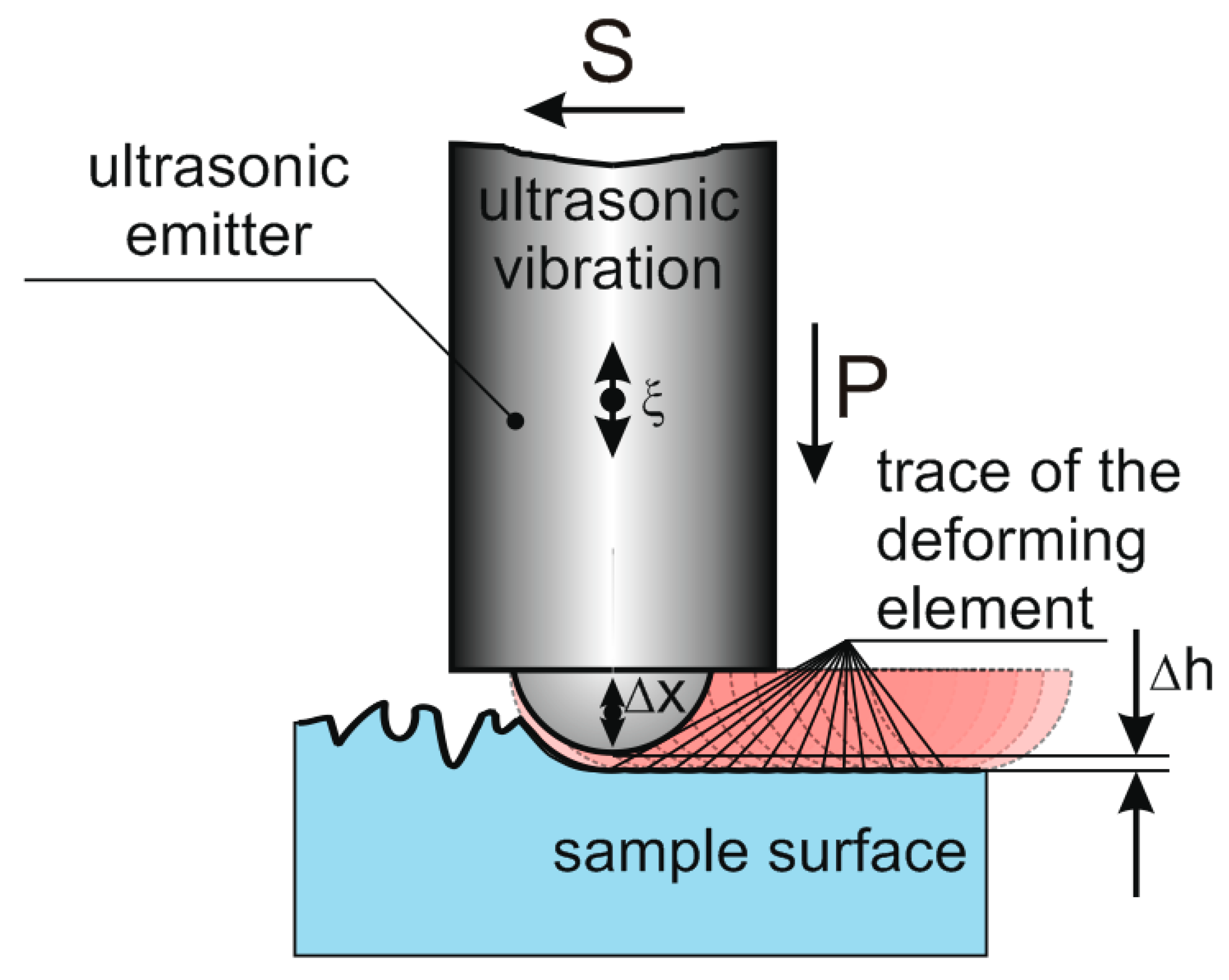
2.2. Experiment Scheme and Equipment
2.3. Methodology for Ultrasonic Surface Plastic Deformation
2.4. Estimation of Structure and Surface Properties
3. Results and Discussion
3.1. Feed
3.2. Pressing Force
3.3. Emitter Oscillation Amplitude
3.4. Initial Sample Roughness and Number of Indenter Passes
4. Conclusions
Supplementary Materials
Author Contributions
Funding
Institutional Review Board Statement
Informed Consent Statement
Data Availability Statement
Conflicts of Interest
References
- Radchenko, V.P.; Saushkin, M.N.; Bochkova, T.I. Mathematical modeling and experimental study of the formation and relaxation of residual stresses in flat specimens from the EP742 alloy after ultrasonic hardening under conditions of high-temperature creep. Bull. Perm Natl. Res. Polytech. Univ. Mech. 2016, 1, 93–112. [Google Scholar] [CrossRef]
- Krylova, N.A. Ensuring the reliability and quality of surfaces of parts by ultrasonic surface plastic deformation. In Proceedings of the International Symposium “Reliability and Quality”, Toronto, ON, Canda, 2–4 August 2018; pp. 205–206. [Google Scholar]
- Abramova, O.V.; Prikhodko, V.M. (Eds.) Powerful Ultrasound in Metallurgy and Mechanical Engineering; Janus-K: Moscow, Russia, 2006; 687p, ISBN 5-8037-0314-1. [Google Scholar]
- Zhang, Y.; Huang, L.; Lu, F.; Qu, S.; Ji, V.; Hu, X.; Liu, H. Effects of ultrasonic surface rolling on fretting wear behaviors of a novel 25CrNi2MoV steel. Mater. Lett. 2021, 284 Pt 2, 128955. [Google Scholar] [CrossRef]
- Lai, F.; Qu, S.; Lewis, R.; Slatter, T.; Fu, W.; Li, X. The influence of ultrasonic surface rolling on the fatigue and wear properties of 23-8N engine valve steel. Int. J. Fatigue 2019, 125, 299–313. [Google Scholar] [CrossRef]
- Li, G.; Qu, S.; Xie, M.; Ren, Z.; Li, X. Effect of Multi-Pass Ultrasonic Surface Rolling on the Mechanical and Fatigue Properties of HIP Ti-6Al-4V Alloy. Materials 2017, 10, 133. [Google Scholar] [CrossRef] [PubMed]
- Zhao, W.; Liu, D.; Qin, H.; Zhang, X.; Zhang, H.; Zhang, R.; Ren, Z.; Ma, C.; Auezhan, A.; Pyun, Y.-S.; et al. The effect of ultrasonic nanocrystal surface modification on low temperature nitriding of ultra-high strength steel. Surf. Coat. Technol. 2019, 375, 205–214. [Google Scholar] [CrossRef]
- John, M.; Ralls, A.M.; Dooley, S.C.; Thazhathidathil, A.K.V.; Perka, A.K.; Kuruveri, U.B.; Menezes, P.L. Ultrasonic Surface Rolling Process: Properties, Characterization, and Applications. Appl. Sci. 2021, 11, 10986. [Google Scholar] [CrossRef]
- Cao, X.; Pyoun, Y.; Murakami, R. Fatigue properties of a S45C steel subjected to ultrasonic nanocrystal surface modification. Appl. Surf. Sci. 2010, 256, 6297–6303. [Google Scholar] [CrossRef]
- Mukhanov, I.I.; GolubevYu, M. Hardening of steel parts with a ball vibrating at an ultrasonic frequency. Vestnikmashinostroeniya 1966, 11, 52–53. [Google Scholar]
- Stebelkov, I.A. The Method of “Surface Hardening”. USSR Patent No. 456704, 15 January 1975. [Google Scholar]
- Ma, C.; Dong, Y.; Ye, C. Improving Surface Finish of 3D-printed Metals by Ultrasonic Nanocrystal Surface Modification. Procedia CIRP 2016, 45, 319–322. [Google Scholar] [CrossRef]
- Ye, C.; Telang, A.; Gill, A.S.; Suslov, S.; Idell, Y.; Zweiacker, K.; Wiezorek, J.M.; Zhou, Z.; Qian, D.; Ramaiah Mannava, S.; et al. Gradient nanostructure and residual stresses induced by Ultrasonic Nano-crystal Surface Modification in 304 austenitic stainless steel for high strength and high ductility. Mater. Sci. Eng. A 2014, 613, 274–288. [Google Scholar] [CrossRef]
- Cherif, A.; Pyoun, Y.; Scholtes, B. Effects of Ultrasonic Nanocrystal Surface Modification (UNSM) on Residual Stress State and Fatigue Strength of AISI 304. J. Mater. Eng. Perform 2010, 19, 282–286. [Google Scholar] [CrossRef]
- Amanov, A.; Karimbaev, R.; Maleki, E.; Unal, O.; Pyun, Y.-S.; Amanov, T. Effect of combined shot peening and ultrasonic nanocrystal surface modification processes on the fatigue performance of AISI 304. Surf. Coat. Technol. 2019, 358, 695–705. [Google Scholar] [CrossRef]
- Mukhanov, I.I. Ultrasonic hardening and finishing of steel and cast iron. Vestnikmashinostroeniya 1968, 6, 51–54. [Google Scholar]
- Rosenberg, L.D. Physics and Technology of Powerful Ultrasound. In Physical Foundations of Ultrasonic Technology; Rosenberg, L.D., Ed.; Science: Moscow, Russia, 1970; Volume 3, p. 689. [Google Scholar]
- Kazantsev, V.F.; Statnikov, E.S. Ultrasonic Surface Plastic Deformation of Solids. In Influence of Powerful Ultrasound on the Interfacial Surface of Metals; Manokhin, A.I., Ed.; Academy of Sciences of USSR: Russia, Moscow, 1986; pp. 186–216. [Google Scholar]
- Suslov, A.G. Technologist’s Handbook; Suslov, A.G., Bezyazyachny, V.F., Bazrov, B.M., Eds.; Publishing House “Innovative Engineering”: Moscow, Russia, 2019; 800p. [Google Scholar]
- Chen, L.; Li, W.; Luo, M. Effect of stacking faults in nanograins on the tensile properties of Mg–Y–Nd–Gd–Zr alloys subjected to ultrasonic surface rolling processing. Surf. Coat. Technol. 2022, 436, 128305. [Google Scholar] [CrossRef]
- Chen, R.; Xue, H.; Li, B. Comparison of SP, SMAT, SMRT, LSP, and UNSM Based on Treatment Effects on the Fatigue Properties of Metals in the HCF and VHCF Regimes. Metals 2022, 12, 642. [Google Scholar] [CrossRef]
- Han, X.; Li, C.; Chen, C.; Zhang, X.; Zhang, H. Fabrication of Low Roughness Gradient Nanostructured Inner Surface on an AISI 304 Stainless Steel Pipe via Ultra-Sonic Rolling Treatment (USRT). Nanomaterials 2021, 11, 1769. [Google Scholar] [CrossRef]
- Xu, C.; Liang, Y.; Yang, M.; Yu, J.; Peng, X. Effects of the Ultrasonic Assisted Surface Rolling Process on the Fatigue Crack Initiation Position Distribution and Fatigue Life of 51CrV4 Spring Steel. Materials 2021, 14, 2565. [Google Scholar] [CrossRef]
- Zhao, X.; Liu, K.; Xu, D.; Liu, Y.; Hu, C. Effects of Ultrasonic Surface Rolling Processing and Subsequent Recovery Treatment on the Wear Resistance of AZ91D Mg Alloy. Materials 2020, 13, 5705. [Google Scholar] [CrossRef]
- Liu, P.; Yu, R.; Gao, X.; Zhang, G. Influence of Surface Ultrasonic Rolling on Microstructure and Corrosion Property of T4003 Ferritic Stainless Steel Welded Joint. Metals 2020, 10, 1081. [Google Scholar] [CrossRef]
- Fernández-Osete, I.; Estevez-Urra, A.; Velázquez-Corral, E.; Valentin, D.; Llumà, J.; Jerez-Mesa, R.; Travieso-Rodriguez, J.A. Ultrasonic Vibration-Assisted Ball Burnishing Tool for a Lathe Characterized by Acoustic Emission and Vibratory Measurements. Materials 2021, 14, 5746. [Google Scholar] [CrossRef]
- Jerez-Mesa, R. Ultrasonic Vibration-Assisted Ball-Burnishing Process. Encyclopedia. Available online: https://encyclopedia.pub/entry/1250 (accessed on 20 December 2022).
- Estevez-Urra, A.; Llumà, J.; Jerez-Mesa, R.; Travieso-Rodriguez, J.A. Monitoring of Processing Conditions of an Ultrasonic Vibration-Assisted Ball-Burnishing Process. Sensors 2020, 20, 2562. [Google Scholar] [CrossRef] [PubMed]
- Kazantsev, V.F.; Prikhodko, V.M.; Fatyukhin, D.S. The Use of Ultrasound in Assembly and Disassembly Operations; Tekhpoligraftsentr Publishing House: Russia, Moscow, 2008; 146p, ISBN 978-5-94385-040-0. [Google Scholar]
- Prikhodko, V.M. Ultrasonic Technology in the Manufacture, Maintenance and Repair of Automotive Engineering; Tekhpoligraftsentr Publishing House: Russia, Moscow, 2003; 253p. [Google Scholar]


| Material | C | Cr | Mn | Ni | Cu | W | Si | Fe |
|---|---|---|---|---|---|---|---|---|
| 45 | 0.46 | 0.09 | 0.55 | 0.27 | 0.1 | 0.01 | 0.21 | 98.31 |
Disclaimer/Publisher’s Note: The statements, opinions and data contained in all publications are solely those of the individual author(s) and contributor(s) and not of MDPI and/or the editor(s). MDPI and/or the editor(s) disclaim responsibility for any injury to people or property resulting from any ideas, methods, instructions or products referred to in the content. |
© 2023 by the authors. Licensee MDPI, Basel, Switzerland. This article is an open access article distributed under the terms and conditions of the Creative Commons Attribution (CC BY) license (https://creativecommons.org/licenses/by/4.0/).
Share and Cite
Fatyukhin, D.S.; Nigmetzyanov, R.I.; Prikhodko, V.M.; Sukhov, A.V.; Sundukov, S.K. Comprehensive Estimation of Changes in the Microgeometry of Steel 45 by Ultrasonic Plastic Deformation with a Free Deforming Element. Metals 2023, 13, 114. https://doi.org/10.3390/met13010114
Fatyukhin DS, Nigmetzyanov RI, Prikhodko VM, Sukhov AV, Sundukov SK. Comprehensive Estimation of Changes in the Microgeometry of Steel 45 by Ultrasonic Plastic Deformation with a Free Deforming Element. Metals. 2023; 13(1):114. https://doi.org/10.3390/met13010114
Chicago/Turabian StyleFatyukhin, Dmitriy S., Ravil I. Nigmetzyanov, Vyacheslav M. Prikhodko, Aleksandr V. Sukhov, and Sergey K. Sundukov. 2023. "Comprehensive Estimation of Changes in the Microgeometry of Steel 45 by Ultrasonic Plastic Deformation with a Free Deforming Element" Metals 13, no. 1: 114. https://doi.org/10.3390/met13010114
APA StyleFatyukhin, D. S., Nigmetzyanov, R. I., Prikhodko, V. M., Sukhov, A. V., & Sundukov, S. K. (2023). Comprehensive Estimation of Changes in the Microgeometry of Steel 45 by Ultrasonic Plastic Deformation with a Free Deforming Element. Metals, 13(1), 114. https://doi.org/10.3390/met13010114