
Deformation Behavior of Two-Phase Gradient Nanograined Fe95Ni5 Alloys under Different Types of Loading


Abstract
:1. Introduction
2. Computational Procedure and Interatomic Potential Validation
3. Results and Discussion
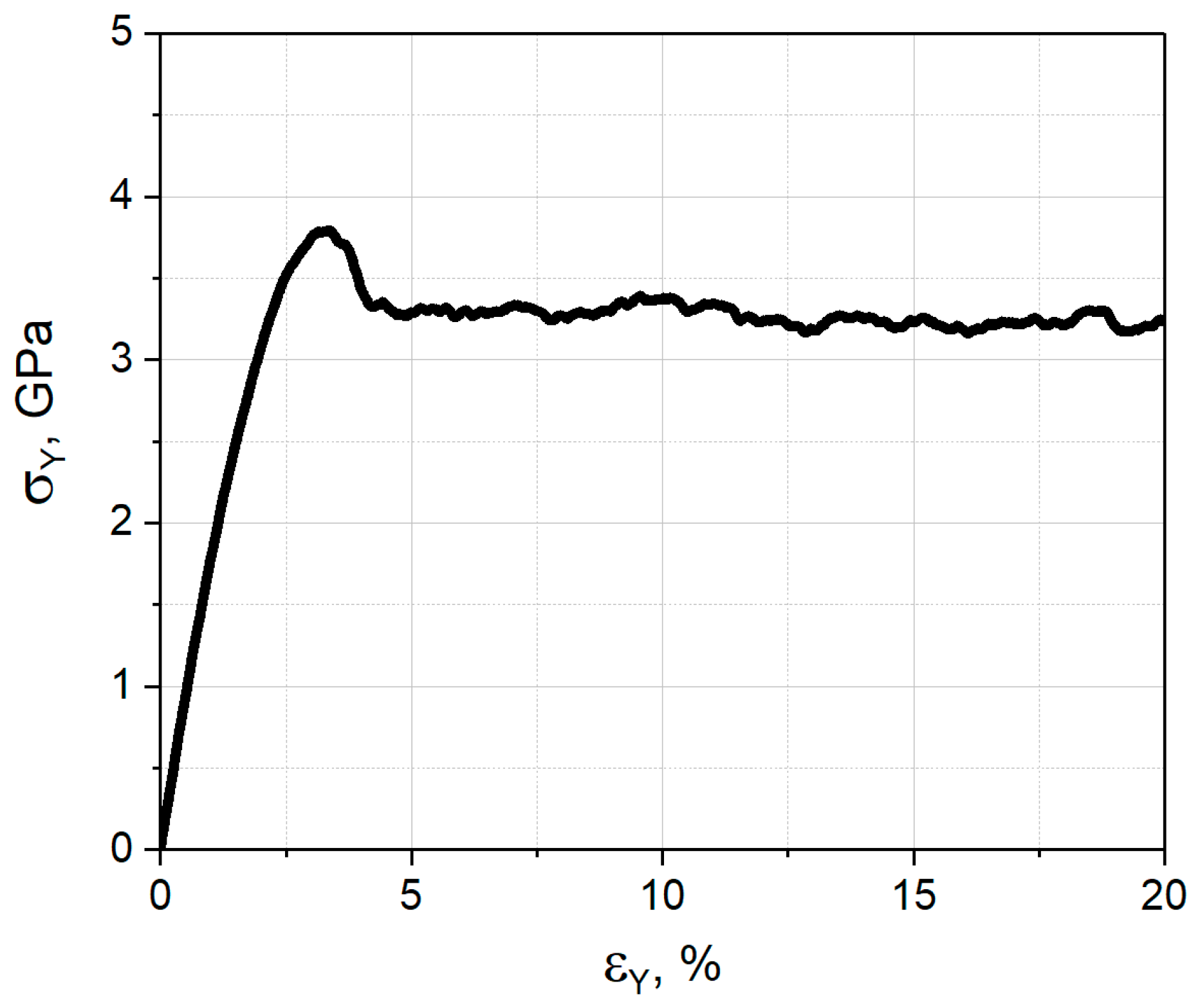
3.1. Uniaxial Tension
3.2. Uniaxial Compression
3.3. Shear
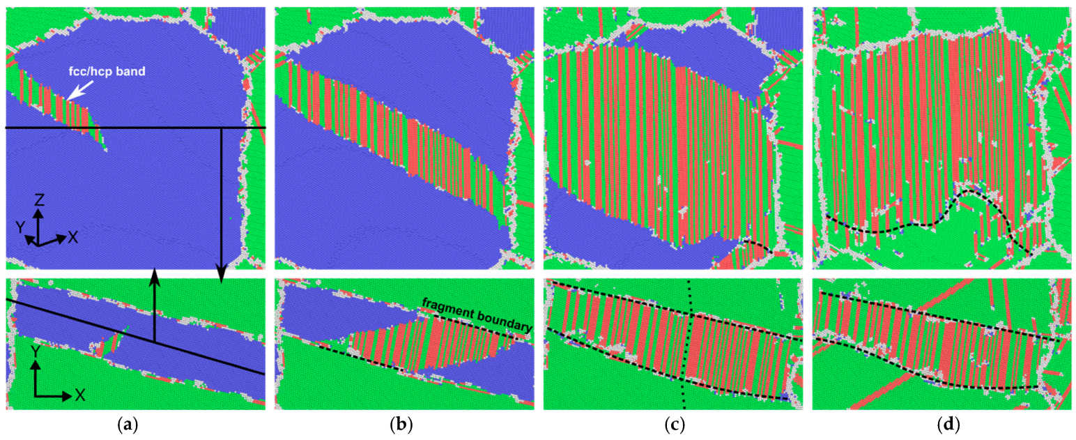
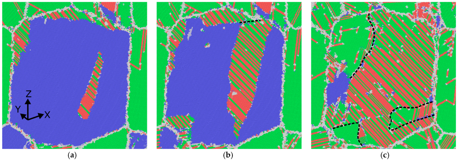
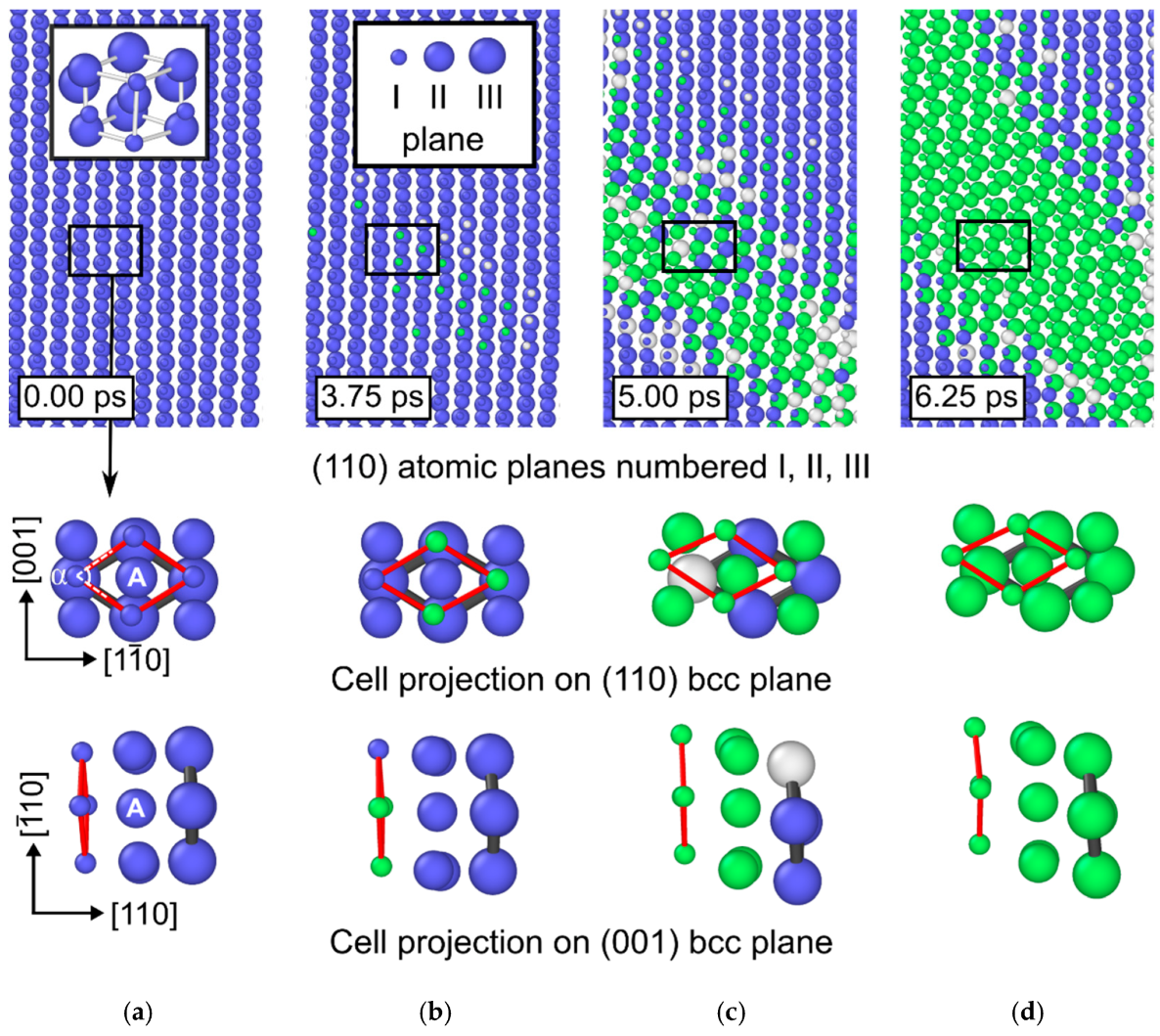
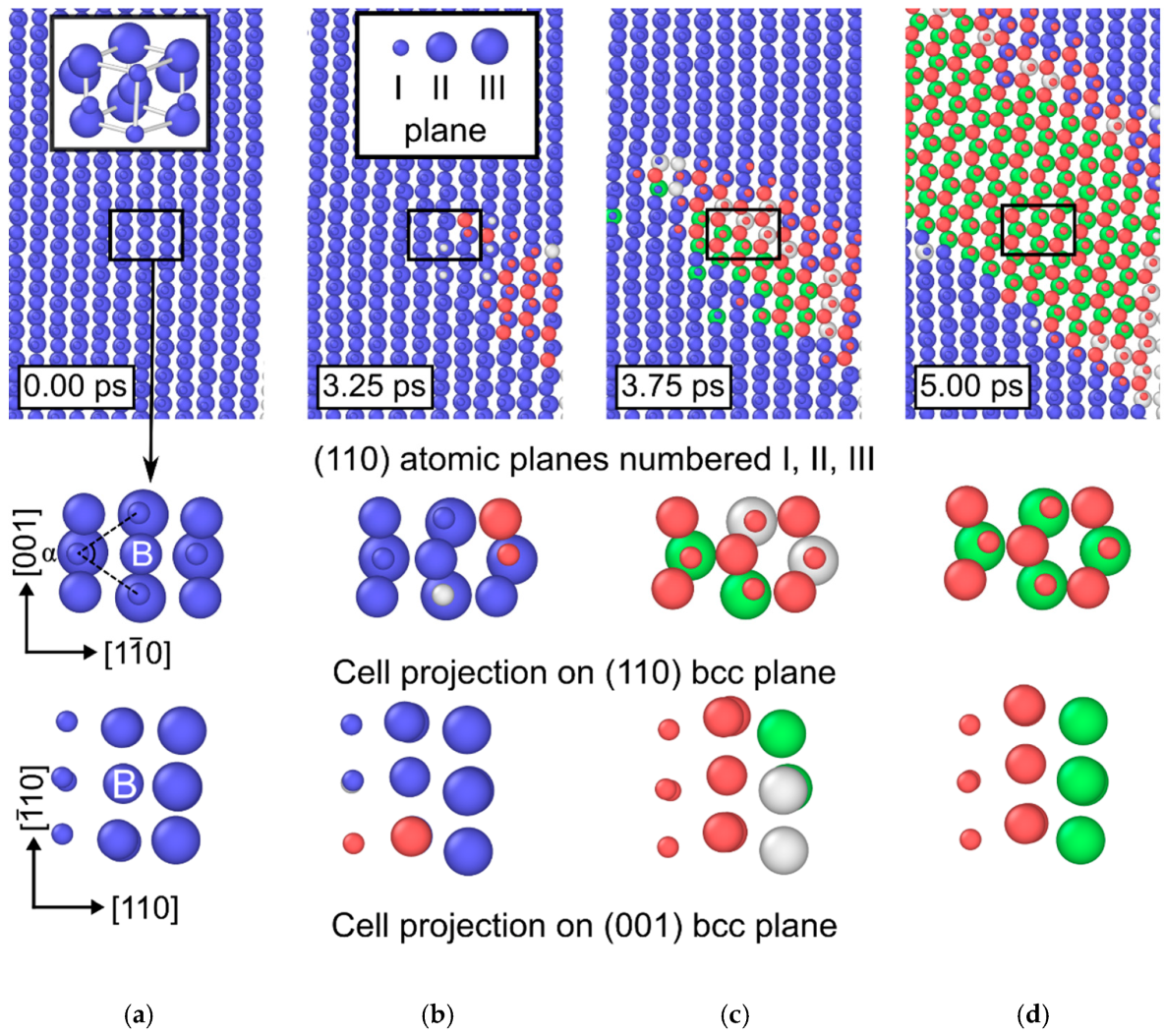
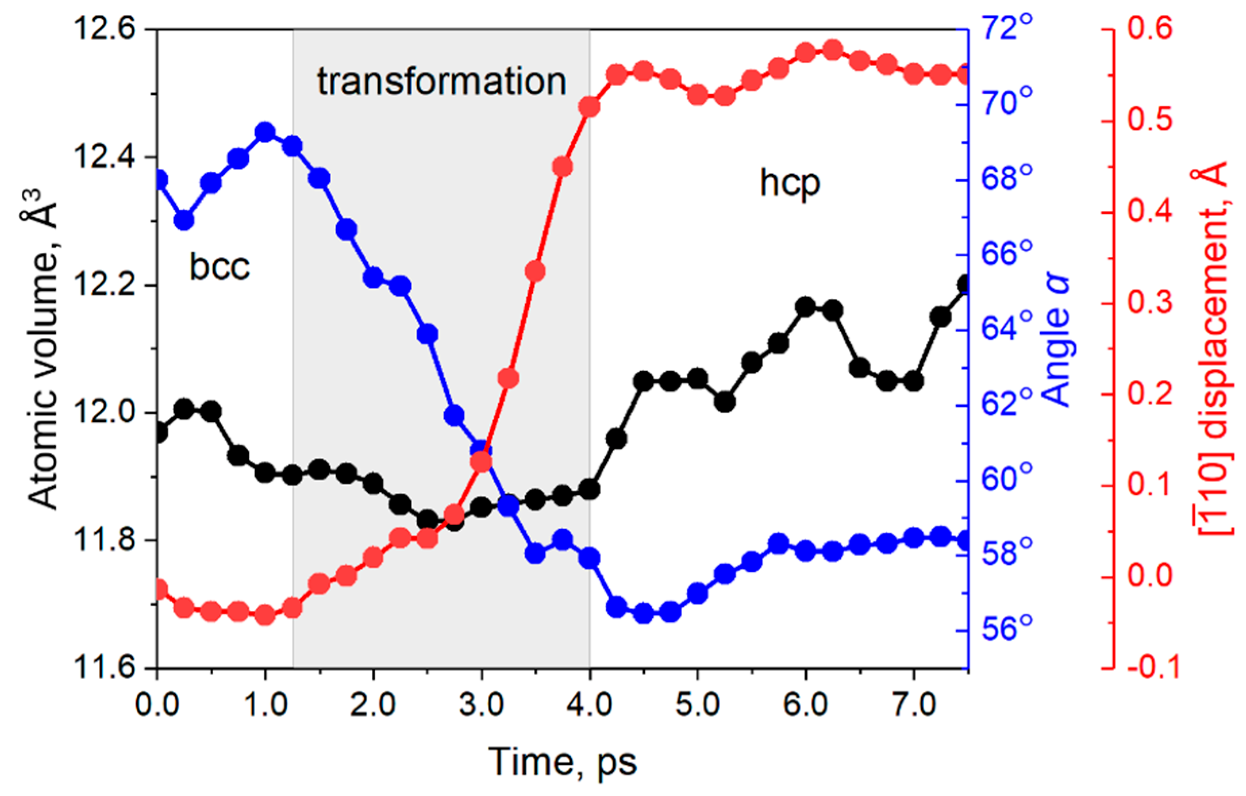
3.4. Atomic Mechanism of the bcc-fcc/hcp Structural Phase Transformation
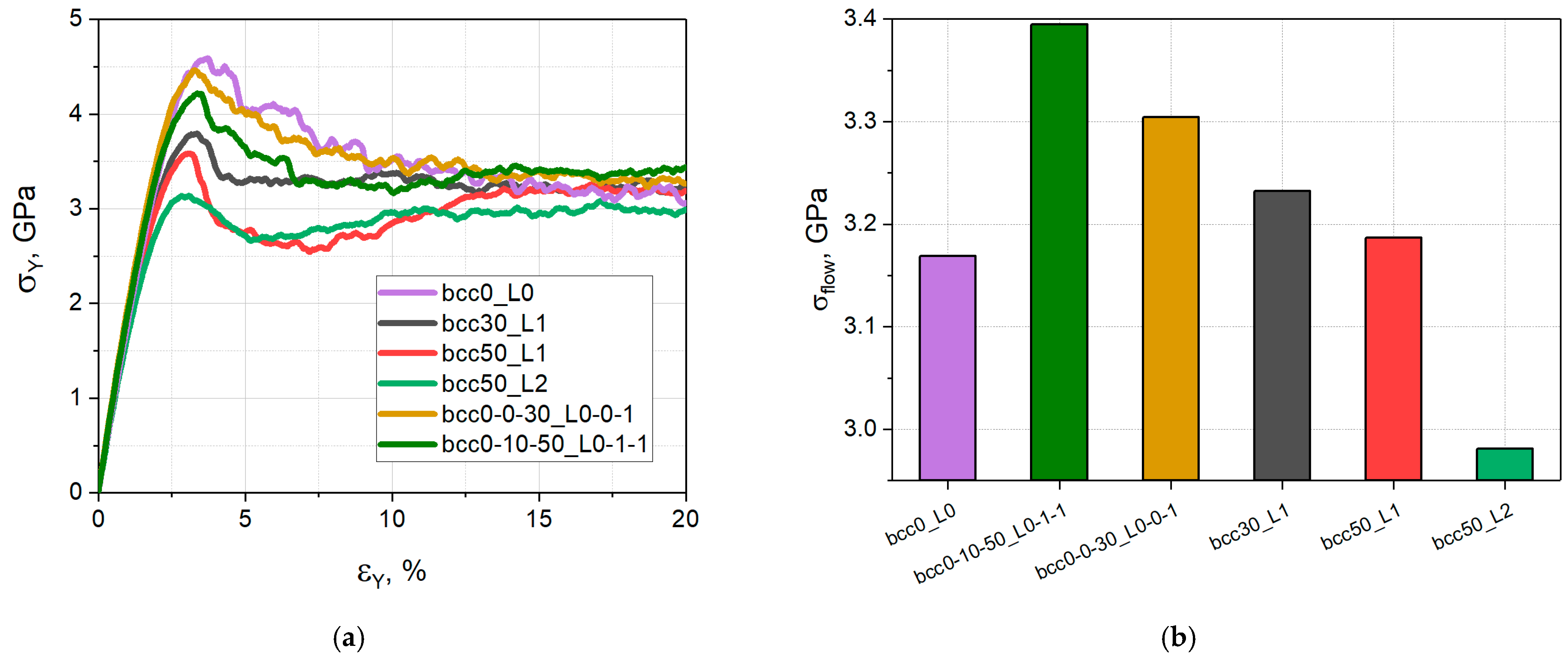
3.5. The Role of the bcc Phase Distribution in the Structural and Mechanical Response of the Simulated Samples
4. Conclusions
Author Contributions
Funding
Data Availability Statement
Conflicts of Interest
References
- Arora, H.S.; Ayyagari, A.; Saini, J.; Selvam, K.; Riyadh, S.; Pole, M.; Grewal, H.S.; Mukherjee, S. High Tensile Ductility and Strength in Dual-Phase Bimodal Steel through Stationary Friction Stir Processing. Sci. Rep. 2019, 9, 1972. [Google Scholar] [CrossRef] [PubMed]
- Wang, Y.; Chen, M.; Zhou, F.; Ma, E. High Tensile Ductility in a Nanostructured Metal. Nature 2002, 419, 912–915. [Google Scholar] [CrossRef] [PubMed]
- Zhang, H.; Wang, H.; Wang, J.; Rong, J.; Zha, M.; Wang, C.; Ma, P.; Jiang, Q. The Synergy Effect of Fine and Coarse Grains on Enhanced Ductility of Bimodal-Structured Mg Alloys. J. Alloys Compd. 2019, 780, 312–317. [Google Scholar] [CrossRef]
- El-Atwani, O.; Quach, D.V.; Efe, M.; Cantwell, P.R.; Heim, B.; Schultz, B.; Stach, E.A.; Groza, J.R.; Allain, J.P. Multimodal Grain Size Distribution and High Hardness in Fine Grained Tungsten Fabricated by Spark Plasma Sintering. Mater. Sci. Eng. A 2011, 528, 5670–5677. [Google Scholar] [CrossRef]
- Xu, T.; Wang, S.; Wang, W.; Liang, P.; Li, X.; Mitsuzaki, N.; Chen, Z. Multimodal Grain Structure and Tensile Properties of Cold-Rolled Titanium after Short-Duration Annealing. Mater. Charact. 2020, 160, 110095. [Google Scholar] [CrossRef]
- Lu, K. Making Strong Nanomaterials Ductile with Gradients. Science 2014, 345, 1455–1456. [Google Scholar] [CrossRef]
- Cao, S.C.; Liu, J.; Zhu, L.; Li, L.; Dao, M.; Lu, J.; Ritchie, R.O. Nature-Inspired Hierarchical Steels. Sci. Rep. 2018, 8, 5088. [Google Scholar] [CrossRef]
- Chen, W.; You, Z.S.; Tao, N.R.; Jin, Z.H.; Lu, L. Mechanically-Induced Grain Coarsening in Gradient Nano-Grained Copper. Acta Mater. 2017, 125, 255–264. [Google Scholar] [CrossRef]
- Cheng, Z.; Zhou, H.; Lu, Q.; Gao, H.; Lu, L. Extra Strengthening and Work Hardening in Gradient Nanotwinned Metals. Science 2018, 362, eaau1925. [Google Scholar] [CrossRef]
- Wang, J.J.; Tao, N.R.; Lu, K. Revealing the Deformation Mechanisms of Nanograins in Gradient Nanostructured Cu and CuAl Alloys under Tension. Acta Mater. 2019, 180, 231–242. [Google Scholar] [CrossRef]
- Cao, R.; Yu, Q.; Pan, J.; Lin, Y.; Sweet, A.; Li, Y.; Ritchie, R.O. On the Exceptional Damage-Tolerance of Gradient Metallic Materials. Mater. Today 2020, 32, 94–107. [Google Scholar] [CrossRef]
- Zhang, Z.; Vajpai, S.K.; Orlov, D.; Ameyama, K. Improvement of Mechanical Properties in SUS304L Steel through the Control of Bimodal Microstructure Characteristics. Mater. Sci. Eng. A 2014, 598, 106–113. [Google Scholar] [CrossRef]
- Li, Z.; Pradeep, K.G.; Deng, Y.; Raabe, D.; Tasan, C.C. Metastable High-Entropy Dual-Phase Alloys Overcome the Strength–Ductility Trade-Off. Nature 2016, 534, 227–230. [Google Scholar] [CrossRef]
- Li, J.; Lu, W.; Chen, S.; Liu, C. Revealing Extra Strengthening and Strain Hardening in Heterogeneous Two-Phase Nanostructures. Int. J. Plast. 2020, 126, 102626. [Google Scholar] [CrossRef]
- Sun, L.; He, X.; Lu, J. Nanotwinned and Hierarchical Nanotwinned Metals: A Review of Experimental, Computational and Theoretical Efforts. NPJ Comput. Mater. 2018, 4, 6. [Google Scholar] [CrossRef]
- Zhang, Z.; Sheng, H.; Wang, Z.; Gludovatz, B.; Zhang, Z.; George, E.P.; Yu, Q.; Mao, S.X.; Ritchie, R.O. Dislocation Mechanisms and 3D Twin Architectures Generate Exceptional Strength-Ductility-Toughness Combination in CrCoNi Medium-Entropy Alloy. Nat. Commun. 2017, 8, 14390. [Google Scholar] [CrossRef]
- Wei, Y.; Li, Y.; Zhu, L.; Liu, Y.; Lei, X.; Wang, G.; Wu, Y.; Mi, Z.; Liu, J.; Wang, H.; et al. Evading the Strength–Ductility Trade-off Dilemma in Steel through Gradient Hierarchical Nanotwins. Nat. Commun. 2014, 5, 3580. [Google Scholar] [CrossRef]
- Wu, X.; Yang, M.; Yuan, F.; Wu, G.; Wei, Y.; Huang, X.; Zhu, Y. Heterogeneous Lamella Structure Unites Ultrafine-Grain Strength with Coarse-Grain Ductility. Proc. Natl. Acad. Sci. USA 2015, 112, 14501–14505. [Google Scholar] [CrossRef]
- Wang, Y.F.; Wang, M.S.; Fang, X.T.; Guo, F.J.; Liu, H.Q.; Scattergood, R.O.; Huang, C.X.; Zhu, Y.T. Extra Strengthening in a Coarse/Ultrafine Grained Laminate: Role of Gradient Interfaces. Int. J. Plast. 2019, 123, 196–207. [Google Scholar] [CrossRef]
- Wang, Y.; Guo, F.; He, Q.; Song, L.; Wang, M.; Huang, A.; Li, Y.; Huang, C. Synergetic Deformation-Induced Extraordinary Softening and Hardening in Gradient Copper. Mater. Sci. Eng. A 2019, 752, 217–222. [Google Scholar] [CrossRef]
- Huang, C.X.; Wang, Y.F.; Ma, X.L.; Yin, S.; Höppel, H.W.; Göken, M.; Wu, X.L.; Gao, H.J.; Zhu, Y.T. Interface Affected Zone for Optimal Strength and Ductility in Heterogeneous Laminate. Mater. Today 2018, 21, 713–719. [Google Scholar] [CrossRef]
- Park, H.K.; Ameyama, K.; Yoo, J.; Hwang, H.; Kim, H.S. Additional Hardening in Harmonic Structured Materials by Strain Partitioning and Back Stress. Mater. Res. Lett. 2018, 6, 261–267. [Google Scholar] [CrossRef]
- Lee, H.H.; Yoon, J.I.; Park, H.K.; Kim, H.S. Unique Microstructure and Simultaneous Enhancements of Strength and Ductility in Gradient-Microstructured Cu Sheet Produced by Single-Roll Angular-Rolling. Acta Mater. 2019, 166, 638–649. [Google Scholar] [CrossRef]
- Korchuganov, A.V.; Zolnikov, K.P.; Kryzhevich, D.S. The Contribution of Various Plasticity Mechanisms to the Deformation Behavior of Gradient Nanograined FeNi Alloy. Metals 2022, 12, 573. [Google Scholar] [CrossRef]
- He, C.-Y.; Yang, X.-F.; Chen, H.; Zhang, Y.; Yuan, G.-J.; Jia, Y.-F.; Zhang, X.-C. Size-Dependent Deformation Mechanisms in Copper Gradient Nano-Grained Structure: A Molecular Dynamics Simulation. Mater. Today Commun. 2022, 31, 103198. [Google Scholar] [CrossRef]
- Plimpton, S. Fast Parallel Algorithms for Short-Range Molecular Dynamics. J. Comput. Phys. 1995, 117, 1–19. [Google Scholar] [CrossRef]
- Zhou, X.W.; Foster, M.E.; Sills, R.B. An Fe-Ni-Cr Embedded Atom Method Potential for Austenitic and Ferritic Systems. J. Comput. Chem. 2018, 39, 2420–2431. [Google Scholar] [CrossRef]
- Honeycutt, J.D.; Andersen, H.C. Molecular Dynamics Study of Melting and Freezing of Small Lennard-Jones Clusters. J. Phys. Chem. 1987, 91, 4950–4963. [Google Scholar] [CrossRef]
- Stukowski, A. Visualization and Analysis of Atomistic Simulation Data with OVITO–the Open Visualization Tool. Model. Simul. Mat. Sci. Eng. 2010, 18, 015012. [Google Scholar] [CrossRef]
- Wang, H.; Liu, Q.; Zhang, J.; Hsu, T.Y. The Size Effect on the Phase Stability of Nanograined Fe–12Ni Powders and the Magnetic Separation of Face-Centred-Cubic-Body-Centred-Cubic Phases. Nanotechnology 2003, 14, 696–700. [Google Scholar] [CrossRef]
- Zheng, H.; Cao, A.; Weinberger, C.R.; Huang, J.Y.; Du, K.; Wang, J.; Ma, Y.; Xia, Y.; Mao, S.X. Discrete Plasticity in Sub-10-Nm-Sized Gold Crystals. Nat. Commun. 2010, 1, 144. [Google Scholar] [CrossRef]
- Psakhie, S.G.; Zolnikov, K.P.; Kryzhevich, D.S.; Korchuganov, A.V. Key Role of Excess Atomic Volume in Structural Rearrangements at the Front of Moving Partial Dislocations in Copper Nanocrystals. Sci. Rep. 2019, 9, 3867. [Google Scholar] [CrossRef]
- Wang, S.J.; Wang, H.; Du, K.; Zhang, W.; Sui, M.L.; Mao, S.X. Deformation-Induced Structural Transition in Body-Centred Cubic Molybdenum. Nat. Commun. 2014, 5, 3433. [Google Scholar] [CrossRef]
- Korchuganov, A.V.; Kryzhevich, D.S.; Chumakov, Y.A.; Grigoriev, A.S. Influence of Grain Size on the Nucleation and Development of Plasticity in Nanocrystalline FeNi Films. IOP Conf. Ser. Mater. Sci. Eng. 2021, 1093, 012012. [Google Scholar] [CrossRef]


| Sample Designations | Fraction of the bcc Phase in Small-, Medium- and Large-Grained Layers, % | The Number of Interlayers in Small-, Medium- and Large-Grained Layers |
|---|---|---|
| bcc0_L0 | 0/0/0 | 0/0/0 |
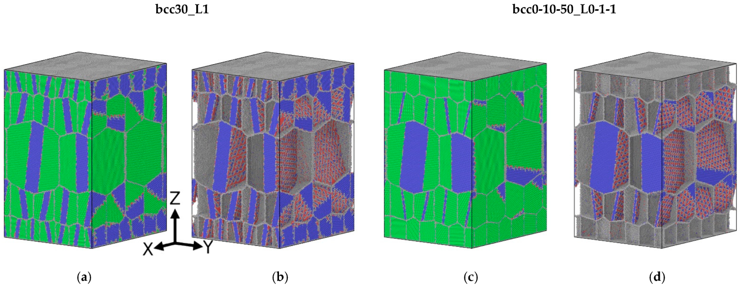
| bcc30_L1 | 30/30/30 | 1/1/1 |
| bcc50_L1 | 50/50/50 | 1/1/1 |
| bcc50_L2 | 50/50/50 | 2/2/2 |
| bcc0-0-30_L0-0-1 | 0/0/30 | 0/0/1 |
| bccC0-10-50_L0-1-1 | 0/10/50 | 0/0/1 |
Publisher’s Note: MDPI stays neutral with regard to jurisdictional claims in published maps and institutional affiliations. |
© 2022 by the authors. Licensee MDPI, Basel, Switzerland. This article is an open access article distributed under the terms and conditions of the Creative Commons Attribution (CC BY) license (https://creativecommons.org/licenses/by/4.0/).
Share and Cite
Korchuganov, A.; Kryzhevich, D.; Zolnikov, K. Deformation Behavior of Two-Phase Gradient Nanograined Fe95Ni5 Alloys under Different Types of Loading. Metals 2022, 12, 1492. https://doi.org/10.3390/met12091492
Korchuganov A, Kryzhevich D, Zolnikov K. Deformation Behavior of Two-Phase Gradient Nanograined Fe95Ni5 Alloys under Different Types of Loading. Metals. 2022; 12(9):1492. https://doi.org/10.3390/met12091492
Chicago/Turabian StyleKorchuganov, Aleksandr, Dmitrij Kryzhevich, and Konstantin Zolnikov. 2022. "Deformation Behavior of Two-Phase Gradient Nanograined Fe95Ni5 Alloys under Different Types of Loading" Metals 12, no. 9: 1492. https://doi.org/10.3390/met12091492
APA StyleKorchuganov, A., Kryzhevich, D., & Zolnikov, K. (2022). Deformation Behavior of Two-Phase Gradient Nanograined Fe95Ni5 Alloys under Different Types of Loading. Metals, 12(9), 1492. https://doi.org/10.3390/met12091492