1. Introduction
In the continuous casting process, the flow field in the mold influences the quality of the final product by affecting the solidification of molten steel, temperature distribution, inclusions, and solution distribution in the mold. If the flow field fluctuates too much, it will cause quality defects of the billet [
1,
2,
3]. Therefore, obtaining the law of the flow field in the mold and designing appropriate control parameters is the key to improving the quality of the billet. Some scholars believe that the physical properties of water are different from those of liquid metals, which cannot fully simulate the actual production conditions, such as the electromagnetic field [
4,
5]. However, due to the convenience and cost-effectiveness of water, the visual water model experiment is an important method to study the flow field in a metallurgical process [
6,
7,
8,
9,
10,
11,
12], and its results can effectively guide the actual production after long-term verification in the metallurgical industry. The qualitative observation of tracers is the most common in water model experiments [
6,
7,
8], and the results of PIV [
10,
11] and UDV [
6] are both good in quantitative observation methods. UDV can also be used for the measurement of the opaque fluid flow field [
4,
5]. Some of these studies have observed the full-field velocity of the mold, and others mainly focused on the fluctuation of the liquid level or velocity changes in a specific area. They all concluded that the large fluctuation of the flow field in the mold would cause problems, such as slag entrainment, leading to the defects of billets. Additionally, the amount of inclusions is much larger during casting variation than during steady casting [
13,
14,
15]. Casting variation states during continuous casting of steel include cast start, cast end, steel grade change, regular casting speed change, and cast fluctuations induced by certain reasons, such as nozzle clogging, which can result in defects, poor quality, and even breakout, involving ladle, tundish, mold, and other equipment [
13,
14,
15,
16,
17]. The head billets, even the first three billets in some cases, often fail to meet the requirements. Further, 80% of surface defects in continuous casting billets originate from the mold [
3], in which most inclusions and bubbles are generated and difficult to remove during casting variation states. Therefore, it is necessary to remove the bubbles and inclusions during casting variation states, especially the cast start. However, the cast variation states, especially the cast start, have received relatively little attention [
13,
14,
15].
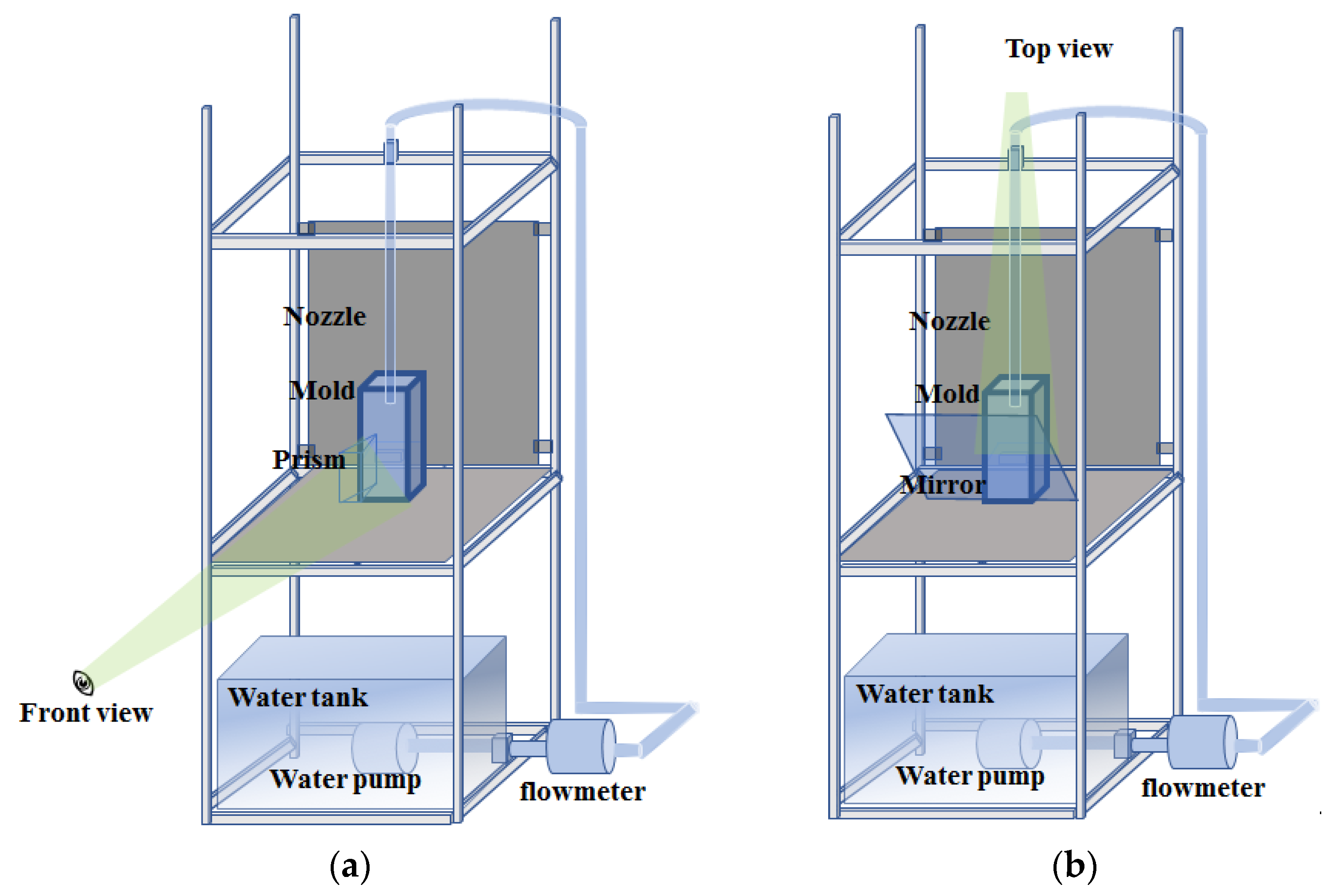
In order to better analyze the flow field in the mold during the cast start, the process of cast start is described here. It includes the filling process and the dragging of a dummy bar. The dummy bar is inserted into the mold before casting to prevent the molten steel from moving out directly. Spring and iron chips are usually laid on the dummy bar to avoid the direct contact of molten steel and promote the molten steel to form a shell during the cast start. Meanwhile, the casting process in the mold is divided into four stages (I–IV) from the beginning to the end of continuous casting (shown in
Figure 1): I—in the cast start process, after laying springs and iron chips on the dummy bar, the jet impinging on the spring and iron chip, the liquid level in the mold is extremely low, that is, the beginning of the filling process; II—the liquid level gradually rises until it reaches the immersion depth, the dummy bar is dragged during this process, that is, the filling process and the dragging of a dummy bar; III—the steady-state stage, the liquid surface is kept at the immersion depth and the continuous casting is carried out stably; IV—the end stage of continuous casting, the liquid level continues to drop until the cast end. During the whole continuous casting, the flow field in the mold is inseparable from the hydraulic jump phenomenon in fluid mechanics. The relationship between the hydraulic jump and continuous casting process is established. The details are as follows:
In stage I, a circular hydraulic jump (CHJ) occurs first (the red arc in the top view of
Figure 1 is a schematic representation of the circular hydraulic jump; it is a shallow fluid hydraulic jump). If there is no boundary, the surface tension plays a leading role at this time, and the surface tension and viscous force are balanced with the momentum of the water film, although gravity does not play a significant role in it (the criterion formula for judgment is 1/We + 1/Fr
2 = 1, We is the Weber number, and Fr is Froude number) [
18]; If there is a boundary, then the flow can quickly reach a steady state, and at this time, the formation of the hydraulic jump is dominated by gravity (common stationary hydraulic jump) [
19,
20]. Stages I and II are studied in this paper, three physical forms of hydraulic jump are defined for better analysis of the flow field and the difference of hydraulic jump in and not in the mold is given: 1st forms—after the jet hits the bottom surface, the circular hydraulic jump starts, the center of the mold is a cavity and a very thin liquid film here, that is, the surface flow (seen in
Figure 2; photos in Figures 6 and 8); that is, the initial formation of a circular hydraulic jump, in which the flow downstream of the jump has not yet arrived at the outlet boundary (it is the mold wall if in the mold), is called a developing jump. Once the flow downstream of the jump arrives at the outlet boundary (not in the mold or low wall), the flow downstream of the jump falls uniformly down from the outlet boundary, and is called a developed jump, the steady-state CHJ, the whole process is a shallow fluid hydraulic jump [
19]. In the filling process, there is a very high boundary (the wall of the mold), and the flow cannot get over it, that is, no downstream exists as the developed jump, no longer a shallow fluid hydraulic jump. After the flow arrives at the wall, then it is blocked and comes back to the center of the mold. The circular hydraulic jump begins to disappear at the moment, which is hereafter called CHJ. The 2nd form—the CHJ disappears and transforms to a common stationary hydraulic jump (hydraulic jump transition begins, it is gradually dominated by gravity), then flows back to the center and fills up the cavity formed by the hydraulic jump. At the moment in stage II, CHJ completely disappears, then a common stationary hydraulic jump begins, which is hereafter called HJT. The 3rd forms—after HJT, the hydraulic jump is mainly dominated by gravity, the liquid surface rises and the flow pattern gradually stabilized, which is similar to meniscus during the steady casting and from a certain moment, the state of the flow pattern basically does not change significantly before the nozzle is immersed (although there is a difference of the flow field between the nozzle immersed situation and not immersed situation), that is, the steady liquid level at the moment, is hereafter called SLL. Until the cast end, the form of the hydraulic jump in stage IV also conforms to a stationary hydraulic jump. As a result, some formulas and experiences applicable to hydraulic jumps can be applied to the continuous casting process.
Besides, the hydraulic jump behavior changes due to liquid jet impingement on patterned surfaces with alternating microscale-ribs and cavities [
21]. Then, different spring and iron chips arrangement on the dummy bar in the filling process should cause the change of the hydraulic jump.
Therefore, this study presents a quasi-three-dimensional hydraulic model experiment of the transient fluid flow phenomena during the cast start (exactly filling process). The flow field is investigated and optimized by controlling the hydraulic jump behavior with adjusting the spring and iron chips arrangement on the dummy bar. Of course, the properties of water and liquid metal are different. In further work, it is necessary to take into account such physical properties of melts as liquid fluidity, microstructure, and especially the near order at the atomic level.
3. Results and Discussion
First, the whole hydraulic jump evolution and its two-dimensional flow field are observed (in
Figure 5,
Figure 6,
Figure 7 and
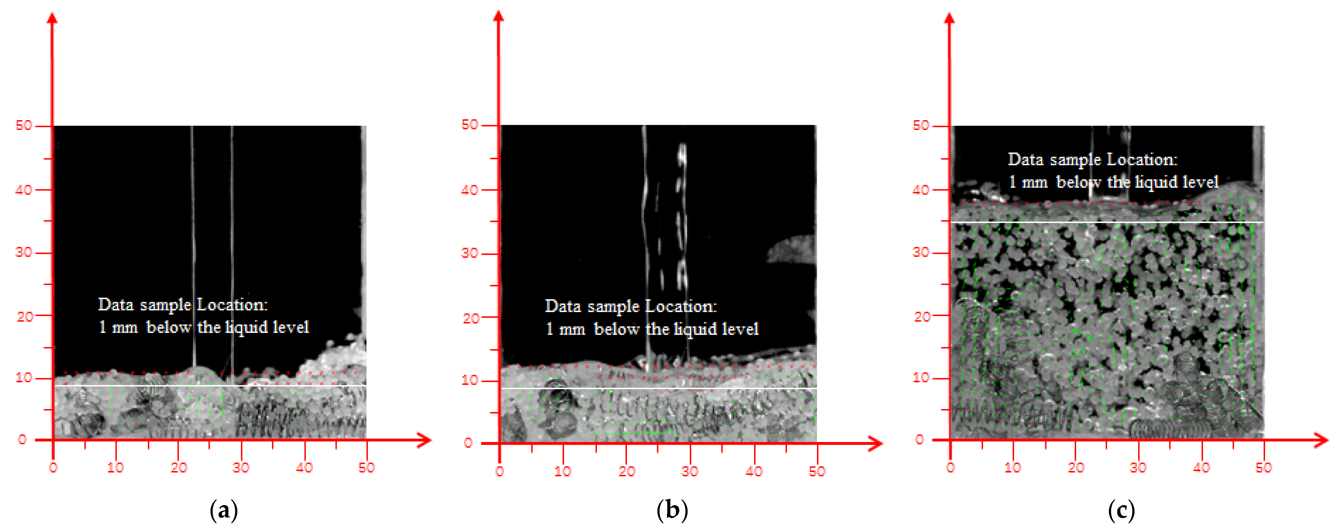
Figure 8). Second, the velocities at 1 mm below the liquid surface in the three forms of the hydraulic jump are quantitatively analyzed (in
Figure 9,
Figure 10,
Figure 11 and
Figure 12, The value position of the velocity data used in
Figure 9,
Figure 10,
Figure 11 and
Figure 12 at 1 mm below the liquid level is also shown in
Figure 4). Finally, the relationship between the spring arrangement, flow, and hydraulic jump are established during the filling process (
Figure 13,
Figure 14 and
Figure 15).
The flow field in three physical forms of the hydraulic jump of the front view (casting speed of 0.8 m/min, modes 1–6) is shown in
Figure 5. The flow formed by the jet moves the spring away from the initial position, then, the initial spring arrangement changes and evolves as the liquid level rises up to the SLL due to buoyancy and the initial velocity of the jet. In CHJ and HJT, the liquid level height and the spring arrangement height are basically the same, that is, the water just submerges the spring, and due to the small amount of liquid, the spring cannot move sufficiently. After HJT, the total amount of liquid increases, the spring is sufficiently buoyant and has enough room to move, and the springs are brought to the liquid surface in some modes, which floats on the liquid surface under the action of buoyancy and surface tension.
The spring and particles arrangement of different modes in the three hydraulic jump forms and changes of arrangement as the liquid level rises after impacted by the jet under the casting speed of 0.8 m/min are shown in
Figure 6 (top view, the particles are all in one layer). The distribution of particles can characterize the flow field, which is driven by the hydraulic jump formed after the impact of the jet; and it develops with the flow to the wall. The black area here in the mold center is the surface flow zone (one typical feature of the circular hydraulic jump forms, the surface flow boundary can be characterized by particles). After the impact by the jet, the springs and particles leave the center of the mold and move to the sidewall. The details are as follows:
Modes 1 and 6: The surface flow is affected by the initial arrangement and the wall of the mold. The hydraulic jump develops more quickly than others, the restraint of the spring arrangement for the hydraulic jump is the smallest.
Modes 2 and 3: the initial spring arrangement looks unchanged, the flow is restricted strictly by the initial spring arrangement in CHJ and HJT. The packing morphology of the particles indicates the occurrence of a circular hydraulic jump with a circular surface flow in the center. Combined with
Figure 3 (front view), it can be seen that the spring arrangement of mode 2 has also undergone great changes after HJT. As the liquid level rises, the springs float above the liquid level, but the initial spring arrangement pattern is basically maintained in SLL. The arrangement of mode 3 is almost kept and does not float (no change).
Modes 4 and 5: since the freedom and stability of the arrangement are moderate, the variation of the arrangement is also between the other modes. The arrangement continues to evolve. Except for mode 3, the springs of other modes float above the liquid level in SLL.
Different from the low casting speed, due to the bigger impact of the jet, the arrangements of modes 1–6 are all broken in CHJ; the particles and springs all leave the center, different modes have different surface flow shapes (central black area in the mold) without particles. The surface flow of modes 1 and 6 is the fastest growing, that of modes 4 and 5 is the next, and modes 2 and 3 is the slowest. No springs float above the liquid and they are suspended in the water by buoyancy in SLL. However, regardless of the high or low casting speed (flow rate), the new arrangement formed by evolution has strong consistency or heritability with the initial arrangement (as shown in
Figure 7 and
Figure 8).
The velocity at 1 mm below the liquid surface in the three forms of the hydraulic jump under the two casting speeds (0.8 m/min, 2.4 m/min) is shown in
Figure 9,
Figure 10,
Figure 11 and
Figure 12. It is an important index for the filling process.
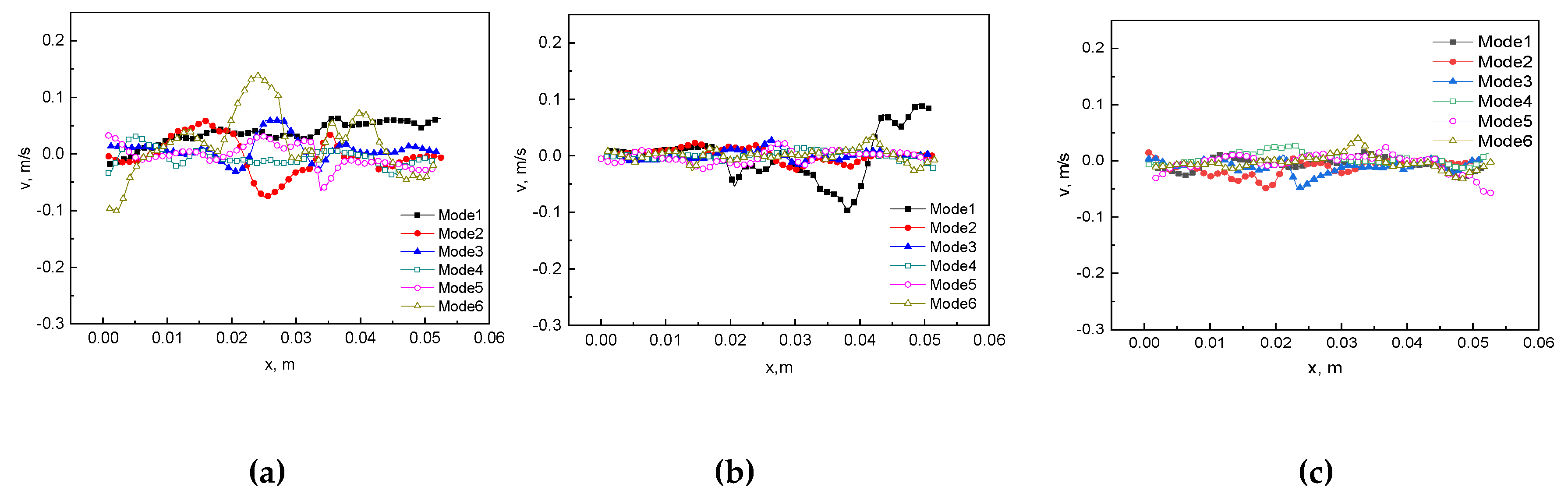
The horizontal component of velocity at 1 mm below the liquid surface in three physical forms of the hydraulic jump (casting speed 0.8 m/min) is shown in
Figure 9. The rightward velocity is defined as a positive direction (x direction). It can be seen that in modes 1–6, as the free surface gradually stabilizes, overall, the velocity near the free surface decreases; free surface fluctuations of CHJ are the largest among the three forms (CHJ, HJT, and SLL); in HJT, the symmetric flows come back to fill up the cavity (surface flow) formed by the hydraulic jump, and flows of modes 1–6 have the similar trend; in SLL, the flow pattern is similar to that of HJT and the velocity decreases, even the asymmetric mode 1 with the largest degree of freedom begins to form a symmetric flow, consistent with the other modes. This quantitatively verifies the influence of the spring arrangement on the hydraulic jump.
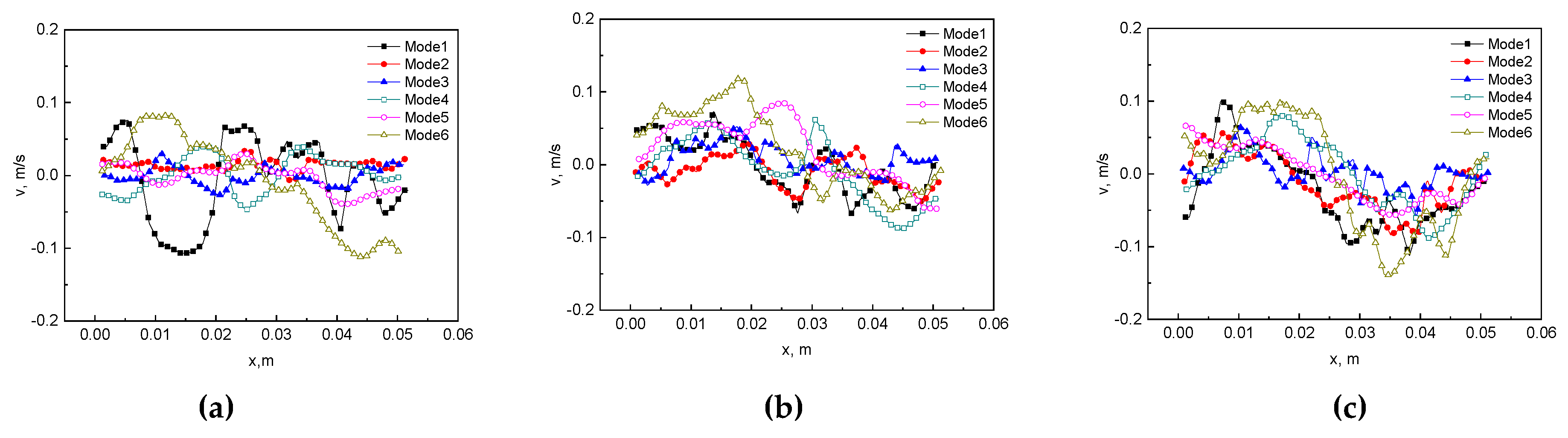
The vertical component of velocity at 1 mm below the liquid surface in three physical forms of the hydraulic jump (casting speed 0.8 m/min) is shown in
Figure 10. The downward velocity is defined as the positive direction (y direction). The conclusions for the vertical components are consistent with those for the horizontal components. Free surface fluctuations of CHJ are the largest among the three forms (CHJ, HJT, and SLL); in HJT and SLL, that of modes 1–6 fluctuate and basically decrease. Combined with
Figure 5,
Figure 9 and
Figure 10, it is a double vortex flow in HJT and SLL.
The horizontal component and vertical component of velocity at 1 mm below the liquid surface in three physical forms of the hydraulic jump (casting speed 2.4 m/min) are shown in
Figure 11 and
Figure 12. It is similar to the case of the casting speed 0.8 m/min, but due to the larger casting speed (initial flow rate), the stability of the liquid level is more difficult and the fluctuation is larger. The flow pattern of the symmetrical backflow is more obvious. Especially, modes 1 and 6, because their arrangements are very small in terms of space constraints, it fluctuates far more than other modes in CHJ. In addition, since the liquid level rises quickly, there is sufficient room for the flow to develop. In SLL, four vortices are formed under the liquid surface (seen in
Figure 7).
The liquid level height of different modes at two different casting speeds in three hydraulic jump forms is shown in
Figure 13. It can be seen that the average liquid level height increases with the increase of the casting speed in general, and the liquid level height in HJT has little relationship with the mode/spring arrangement.
At 0.8 m/min casting speed, the liquid level/height of the hydraulic jump changes as follows:
- CHJ:
the hydraulic jump height/depth of modes 4 and 5 is the lowest and about 9 mm; the maximum height of modes 1, 2, 3, and 6 can reach 15–18 mm.
- HJT:
There is no obvious difference in the overall liquid profile among modes 1–6; and the average heights of the liquid surface are almost the same in modes 1–6, about 9 mm.
- SLL:
the liquid level is relatively smooth (but it does not mean the fluctuation velocity value around the liquid surface is small), with a height of about 15–22 mm.
At 2.4 m/min casting speed, the liquid level/height of the hydraulic jump changes as follows:
The flow field at the high casting speed (2.4 m/min) is similar to that at the low casting speed (0.8 m/min), but obviously as the flow rate increases, the velocity in the mold increases and the liquid level rises fast.
- CHJ:
the average hydraulic jump height of modes 2–6 is low and about 13 mm; the maximum height of mode 1 can reach 26 mm.
- HJT:
There is no obvious difference in the overall liquid profile among modes 1–6; and the average heights of the liquid surface are almost the same in modes 1–6, about 11–13 mm.
- SLL:
the liquid level is also relatively smooth (but it does not mean the fluctuation velocity value around the liquid surface is small), with a height of about 44 mm, except mode 1 is 35 mm.
At a low casting speed of 0.8 m/min: the liquid level height in CHJ is the height of the the circular hydraulic jump (it is the height after jump; the center of the mold is a cavity and very thin liquid film here, that is, surface flow), the heights of modes 1, 2, 3, and 6 in CHJ are high, and they even exceed the liquid level height in SLL. Modes 4 and 5 are relatively low, which is almost the same as that in HJT, then the kinetic energy loss is smallest, that is, if the liquid level height is low in CHJ, then the liquid level height is high in SLL. The liquid level increases with the time and reaches the highest in SLL. At a high casting speed of 2.4 m/min: The liquid level of modes 2–6 is basically the same in all three forms, while the liquid level of mode 1 rises in CHJ and decreases obviously in SLL. The liquid level of different modes in HJT at the two casting speeds are almost the same—all modes have a similar trend. It can generally be attributed to the influence of the spring arrangement and characteristics of the hydraulic jump in the filling process.
The duration of the three transition processes of the hydraulic jump (CHJ, HJT, and SLL) is another important parameter. The duration of CHJ for modes 1 and 6 is half of the other modes; the flow rate/casting speed has little effect on the duration, and the duration of different modes is basically the same at the two casting speeds, as shown in
Figure 14a. CHJ to HJT is a transitional process from a circular hydraulic jump to a common stationary hydraulic jump, the duration of CHJ to HJT, as shown in the
Figure 14b. In this process, the duration of different modes is also basically similar at the two casting speeds and increases with the increase in flow. HJT to SLL is a common stationary hydraulic jump (two or four vortices forms and the liquid level relatively stable), duration of HJT to SLL, as shown in the
Figure 14c. The duration of CHJ depends entirely on the spring arrangement (spring arrangement varies after the hitting by jet). The duration of CHJ to HJT increases with the flow and also depends on the spring arrangement. The duration of HJT to SLL also depends on the spring arrangement. It is clarified that designing different arrangements can indeed adjust the hydraulic jump behavior. However, these two indicators cannot yet determine which.
In order to better characterize which kind of laying (modes 1–6) is beneficial to the filling process, a filling coefficient w (nondimensional velocity) is set.
|v
F|—the absolute value average of fluctuation velocity at liquid level (the average velocity at 1 mm below the liquid surface) in CHJ, HJT, and SLL, |v
R|—the absolute value of the average liquid level rise velocity in CHJ, HJT, and SLL. v
R = (the average height of liquid level in CHJ, HJT, SLL)/(duration from start point to CHJ, HJT, SLL), the average height can be obtained from
Figure 5 and
Figure 7 (front view).
An increase in the filling coefficient w indicates an increase in fluctuation or a decrease in liquid level rise velocity. The flow field for the filling process needs to be stable and fast to fill the mold. The smaller the filling coefficient, the more the filling process meets the metallurgical goal. The filling coefficient w applies to the entire filling process before stage III. Additionally, w has a relatively obvious correlation with flow and spring arrangement (shown in
Figure 15).
At a low casting speed of 0.8 m/min: w of modes 1 and 6 in CHJ is different from that of the other two forms (HJT and SLL); and w of modes 2–5 has similar laws in the three forms (CHJ, HJT, and SLL). w of modes 3–5 is small in CHJ and SLL, w of mode 2, 4, and 5 increases significantly in HJT. At a high casting speed of 2.4 m/min: the law of w in the three forms basically obeys the mode (arrangement). w of modes 1, 4, and 6 is large, while w of modes 2, 3, and 5 is relatively small.
In general, w is the largest at HJT, followed by SLL, and CHJ is the smallest. w is small for closely arranged modes, while w increases for loosely and unstable modes; the change of w in CHJ is smaller than that in HJT and SLL for all modes. The different spring arrangements really affect the hydraulic jump. Modes 2, 4, and 5 are also good performance. At a low casting speed of 0.8 m/min, only the initial arrangement of mode 3 is kept. The best operation condition is mode 3 at a low casting speed. Its structure is tight enough and stable.
For the hydraulic jump, surface tension plays the role in CHJ, gravity plays the role in SLL, and from CHJ to HJT, surface tension decreases, gravity increases; this process is a dynamic balance between surface tension and gravity [
18,
19]. The HJT is the critical transition node from which gravity exceeds surface tension.
Meanwhile, according to the visualization results, it can be seen that the initial spring arrangement forms a new arrangement structure after being impacted by jet, and the evolution process of this new structure is affected by the initial arrangement and the jet. Then, the new arrangement influences the hydraulic jump.


