Article

The Mechanical Performance of Aluminum Foam Fabricated by Melt Processing with Different Foaming Agents: A Comparative Analysis

1
Frantsevich Institute for Problems of Materials Science, National Academy of Sciences of Ukraine, 3 Krzhyzhanovsky St., 03142 Kyiv, Ukraine
2
Physical-Technological Institute of Metals and Alloys, National Academy of Sciences of Ukraine, 34/1 Vernadsky Ave., 03142 Kyiv, Ukraine
*
Author to whom correspondence should be addressed.
Metals 2022, 12(8), 1384; https://doi.org/10.3390/met12081384
Submission received: 6 July 2022 / Revised: 3 August 2022 / Accepted: 15 August 2022 / Published: 20 August 2022

Abstract

:
The study presents the comparative analysis of the compressive response for the experimental aluminium foams of different parent alloys fabricated by melt processing with/without Ca additive and an expensive conventional TiH2 foaming agent or a cheap alternative CaCO3. It was recognized that the response of the foams is significantly dependent on the type of foaming agent and Ca additive due to the formation of low ductile and brittle products created in the foaming process. The presence of deformation bands and brittle eutectics in material, Al3Ti particles/layers, partially decomposed TiH2, Ca containing compounds, etc. cause a reduction of the foam’s compressive strength and deviation of its mechanical profile from the theoretical predictions. In addition, the usage of an inexpensive CaCO3 foaming agent offers numerous indisputable advantages compared to TiH2, resulting, particularly, in enhancing the energy absorption ability of foams.

1. Introduction

Aluminum foams of a closed-cell structure are considered as multifunctional materials attractive for different applications due to their unique combination of light weight and new physical and mechanical properties [1,2]. In addition, the stiffness/mass ratio for the foams is much higher than that of known aluminum alloys. The important point concerns the fact that aluminium foams demonstrate at compression extraordinary energy absorption, which particularly depends on the parent alloy composition and processing variables used in the foaming process. For some aluminium foams, the enhancement of energy absorption is finally realized by an increase in plateau stress, while for other foams a similar result may be achieved due to a long deformation plateau extended up to 50–70%, whereas increasing the stress is not significant. In addition, sound absorption and vibration damping capacity, low thermal conductivity, and other attributes important in the design of structural components are found to be inherent characteristics of aluminum foams, making them promising for usage in different sectors of industry. In particular, aluminum foams may be used in civil engineering for improvement of urban ecology, including life style by diminution of noise [3], protection against electromagnetic waves [4], heat insulation [5], as well as in transportation manufacturing, including ground and marine vehicles, and also in the aircraft industry [6,7,8]. Moreover, aluminum foam as a core material is efficient in lightweight sandwich panels [9] and crashworthy integral components against crash collision and blast protection [10,11].
The potential of aluminum foams to be used in different industrial sectors stimulated extensive interest for a search of appropriate parent alloys and attractive processing routes adapted to the design of engineering constructions. To date, the numerous foaming processes, such as dispersion of a gas in liquid metal, the powder compact technique, and foaming with blowing gas agents similar to Alporas® (Japan) route were developed and discussed [12]. The last route is considered to be the most economically attractive, providing also more uniform cellular structure with smaller cells [13]. However, the use of an expensive titanium hydride TiH2 as a foaming agent and granulated Ca as a thickening agent stipulates essential material cost in mass production. So, economic efficiency for melt processing may be improved by using cheap calcium carbonate CaCO3, which was originally proposed as an alternative foaming agent in [14].
In addition, the cell size of such aluminum foams is at least 2 times smaller, owing to oxidation of the cell surface [14,15]. However, studies addressed to the use of CaCO3 are not enough [14,15,16,17,18], some of them concern an important improvement, i.e., replacement of costly granulated Ca either by technological efforts [19] or by using inexpensive alternative thickening additives [20,21,22,23].
In any way, transfer of aluminum foams to an engineering practice cannot be realized without understanding the limits of the foaming process and a detailed knowledge of the foamed material’s properties, especially the mechanical properties. It is common knowledge that the mechanical response of foams is dependent on the relative density, ρ/ρs (where ρ and ρs are, respectively, density of foam and solid), although composition of parent alloy and processing conditions (method and processing additives) contribute essentially in the level of their performance metrics [13].
Unfortunately, the theoretical predictions of an idealized porous structure, which are summarized in [13], do not represent the experimental results of mechanical tests of true foams. The deviation of aluminium foam performance metrics from theoretical predictions occurs due to the effect of different structural imperfections, such as corrugation of cell faces, micro pores, ductile/brittle eutectic domains inherent for parent aluminum alloys, and also other side products involved in the foaming process [15,16,24,25]. Therefore, the experimental verification of the mechanical profile for real aluminium foams is strongly required.
The mechanical properties for aluminum foams created by Alporas® route with TiH2 and Ca, which were reported in numerous publications, are well presented and summarized in [2,13], whilst reports on the melt process with CaCO3 with and without Ca are small in number [13,15,16,22,23,24,25,26].
Moreover, the data concerning the comparison of the mechanical profiles of foams are sometimes fragmentary and even rather ambiguous because of arbitrary determinations of the compressive strength.
The effort of the present study concerns the comparative analysis of the processing condition’s influence, i.e., necessary melt foaming and thickening additives on the mechanical performance metrics of aluminum foams of different compositions fabricated by the melt route similar to Alporas® technique. The consideration is mainly focused on the compressive strength and, especially, on the energy absorption ability of the foams created by calcium carbonate in comparison with those processed by titanium hydride.

2. Materials and Methods

2.1. Materials and Processing

Table 1 presents the experimental aluminum foams of different grades denoted as F1–F10, as well as their microstructural features reviewed previously in [15,16,24,25] and solid yield strength of the cell wall material tested here.
Pure aluminum (purity 99.95) was used in the design of F1, F2 foams, while conventional cast alloy of composition Al-Si (similar to A356 alloy) and relatively ductile Al-Si-Mg alloy (analogous to 6061 alloy) were employed to create F3, F4 and F5, F6 foams, respectively. In addition, two kinds of high-strength wrought Al-Zn-Mg alloys of different compositions (analogous to 7075 alloys) were exploited for fabrication F7–F10 foams. Among them, Al-Zn-Mg alloy comprising Sc and Zr (less than 0.6 wt.%) was taken to produce F7, F8 foams. The parent alloys density for F1–F6 foams was equal to 2.7 g/cm3, whereas the density of alloys used for F7–F10 foams was of 2.8 g/cm3.
The melt process was realized with or without Ca as a thickening agent, while the melt foaming was done by adding either titanium hydride or calcium carbonate [15,16,19,26]. The foaming temperature was kept higher of the liquidus temperature of the corresponding parent alloys. Mixing velocity was chosen by considering the viscosity of the melt depending on the composition of the parent alloy and the kind and powder particles of the foaming agent. Further details of the manufacturing process of the foams under study and other relevant parameters can be found elsewhere [15,16,19,26].
Foamed cylindrical ingots with a diameter of 90 mm and a height of approximately 180 mm were fabricated and then the samples were cut by an electro-discharge apparatus for further testing.
The samples of alloys with a composition similar to the foamed material were prepared by casting and underwent the conventional compression tests to get mean values of solid yield strength (Table 1) for the studied dense alloys.

2.2. Structural Characterization

The relative density ρ/ρs of Al-foam samples were evaluated by weighing method. The shape and size of the cells and also the microstructure of the cell wall material were analyzed by electron microscopy Jeol Superprobe-733 (JEOL, Tokyo, Japan).
Al-foams processed with TiH2 consisted of the cells, whose size was approximately 3 mm, whereas the cell size of Al-foams created by CaCO3 was at least two times smaller.
The distinctive features of the cell wall microstructure were partly adopted over the reports previously published [15,16,24,25,26,27,28] and complemented by the results in the present study.

2.3. Mechanical Testing

The mechanical response of the Al-foams was performed under uniaxial compression according to ISO 13314:2011. The rectangular specimens either of a 20 mm × 20 mm or a 30 mm × 30 mm cross-section base were cut to keep away undesirable size effect.
The data were recorded by the universal test machine CERAMtest System (IPS NASU, Kyiv, Ukraine) of 20 kN by applying compressive force with constant crosshead speeds. The strain rates were ranged from 1 × 10⁻³ to 1 × 10⁻² for at least three samples to validate the results’ reliability and to select typical stress–strain curves for presentation.
The mechanical parameters were evaluated by analysing the stress–strain curves. Among them, the plateau stress, σpl, energy absorption W50 up to 50% strain and Wpl up to the end of deformation plateau were defined. In line with the standardized recommendation, plateau stress, σpl, was defined as arithmetical mean of the stresses at 0.1% strain intervals between 20% and 30% or 20% and 40% compressive strain. In addition, the plateau end was found as the point in the stress–strain curve at which the stress is 1.3 times the plateau stress. Energy absorption W50 and Wpl were estimated by proper areas under the stress–strain curve up to 50% strain and up to the plateau end strain, εpl. Attention was paid to the fact that W50 and Wpl were initially defined per unit volume (MJ/m3) and then they were recalculated in J/g to avoid misunderstanding caused by different density of the parent alloys.
In addition, energy absorption efficiency denoted by ISO 13314: 2011 as Wef50 and Wefpl were calculated in percentages (%) by using the corresponding performance metrics for energy absorption W50 and Wpl per unit volume (MJ/m3):
W ef   = W ε 0   × σ max ×   10 4
where σmax corresponds to the maximal compressive stress observed within the proper area of the stress–strain curve.

3. Results and Discussion

3.1. Compressive Response of Al-Foams

Generally, macroscopic behaviour of all foamed alloys under compression is quite close to an elastic/plastic response [1,2,12], although the substantial differences of microscopic deformation are found in the plateau region. Figure 1 shows compression curves for the studied foams.
In particular, a smooth deformation plateau being typical for plastic buckling of the cell walls is representative for an F2 foam since its deformation band material contains ductile structural constituents and, particularly, eutectic regions [15,27]. In addition, only several oscillations are visible in the stress plateau of an F6 foam, implying the significant contribution of the cell wall’s plastic buckling [1,13]. This argumentation is confirmed by the extremely high level of plateau stress of an F6 foam being situated far above that demonstrated by an F5 foam, although both foams are of the same parent alloy and comparable relative density, ρ/ρs. This is because tensile membrane stress affecting closed cell faces causes the plateau stress to rise up, making the hardening rate extraordinarily fast [2]. As opposed to the above, more or less hardening/softening sequences are observed within plateau stress, implying cell collapse by fracture [29,30].
For instance, the use of titanium hydride in the creation of F1, F3, and F5 foams introduces into the cell walls, material with undesirable brittle residues of partially converted TiH2 covered by Al2Ti/Al3Ti, which originates cell failure and, as a consequence, plateau stress oscillations. Moreover, the presence of brittle eutectic domains/redundant phases in the microstructure of high-strength parent alloys being used in the creation of F7, F8, F9, and F10 foams causes plateau stress oscillations to be the most pronounced. In addition, the presence of high strength Al3(ScZr) particles/crystals being randomly scattered over the cell wall material induces the first local maximum of compressive stress, causing plateau stress to get a saddle shape [15,16,24,26,27]. It should be noted that the use of Ca as a thickening agent for F5, F7, and F9 foams processed by TiH2 causes plateau stress to come down compared to that observed for F6, F8, and F10 foams prepared with CaCO3, without the addition of Ca. This is because of the role of CaCO3 in the significant improvement of deformation patterns of the foams due to cleaning the cell walls from undesirable contaminating side products introduced by TiH2 [15,16,24,26,27].
Moreover, the use of CaCO3 in production processes of F8 and F10 foams with high-strength parent alloys provides smoother stress–strain curves with more slight oscillation of plateau stress than those demonstrated by F7 and F9 foams, which were produced with TiH2 and the same parent alloys.
Thus, it can be assumed that the processing variables, including composition of parent alloys, strongly influences cell collapse, which, in turn, defines the compressive response of the foams. In addition, the compression stress–strain behavior of the foams significantly depends on the structural constituents and undesirable foreign particles/compounds, all presented in the cell wall material.

3.2. Compressive Strength of Al-Foams

Comparative analysis of the mechanical performance of the foams is implemented in line with approach [13], which provides the presentation of relative compressive strength σpl/σys plotted versus relative density ρ/ρs, as shown in Figure 2.
As evidenced from Figure 2a, only data for the compressive strength of F2 foam, which is based on Al and produced with CaCO3, lies along with line representing the theoretical approach for closed-cell foams, implying elastic buckling and yielding of deformation bands. However, data for all other closed-cell foams deviate from the line prescribed by the theory. Among them F1, F3, F5, F7, and F9 foams processed with TiH2 deviate the most. This is because brittle reaction products contained by cell wall material impair the compressive strength of F1, F3, and F5 foams formed with TiH2 and Ca as processing additives.
In addition, brittle constituents, which are natural for a microstructure of high strength parent alloys used for F7 and F9 foams being processed with TiH2 provoke impairment of the compressive strength due to increased cell cracking. For illustration, data related to the foam based on Al and produced with TiH2 shifts down the line prescribed for open cell foams by the theoretical approach, while the data for compressive strength of F3 and F5 foams as well as F7 and F9 foams being processed with TiH2 lie either at least along or even somewhat below the line referred to above. In fact, the data related to the compressive strength of F4, F6, and F10 foams being produced with CaCO3 lie more or less below the line prescribed for closed-cell foams, although they are revealed to be higher than the data of F3, F5, and F9 foams generated with TiH2. It should be noted that this is because the extremely small width of deformation bands, which are considered generally to be approximately 100 μm and less when foam relative density, ρ/ρs, becomes extraordinarily diminutive.
At these conditions, premature damage of deformation bands can occur, resulting in a drop in foam compressive strength. That is perhaps the reason why the data related to the compressive strength of F2, F6, F10, and F5 foams decreases by jumping below the line prescribed for open cell foams, when their relative density becomes less than ρ/ρs < 0.20. Again, the results of the comparative analysis confirm the advantages concerning the use of CaCO3 as an alternative foaming agent in view of retaining high compressive strength, owing to the cleaning material of deformation bands from the undesirable brittle side products created when TiH2 and Ca are used.

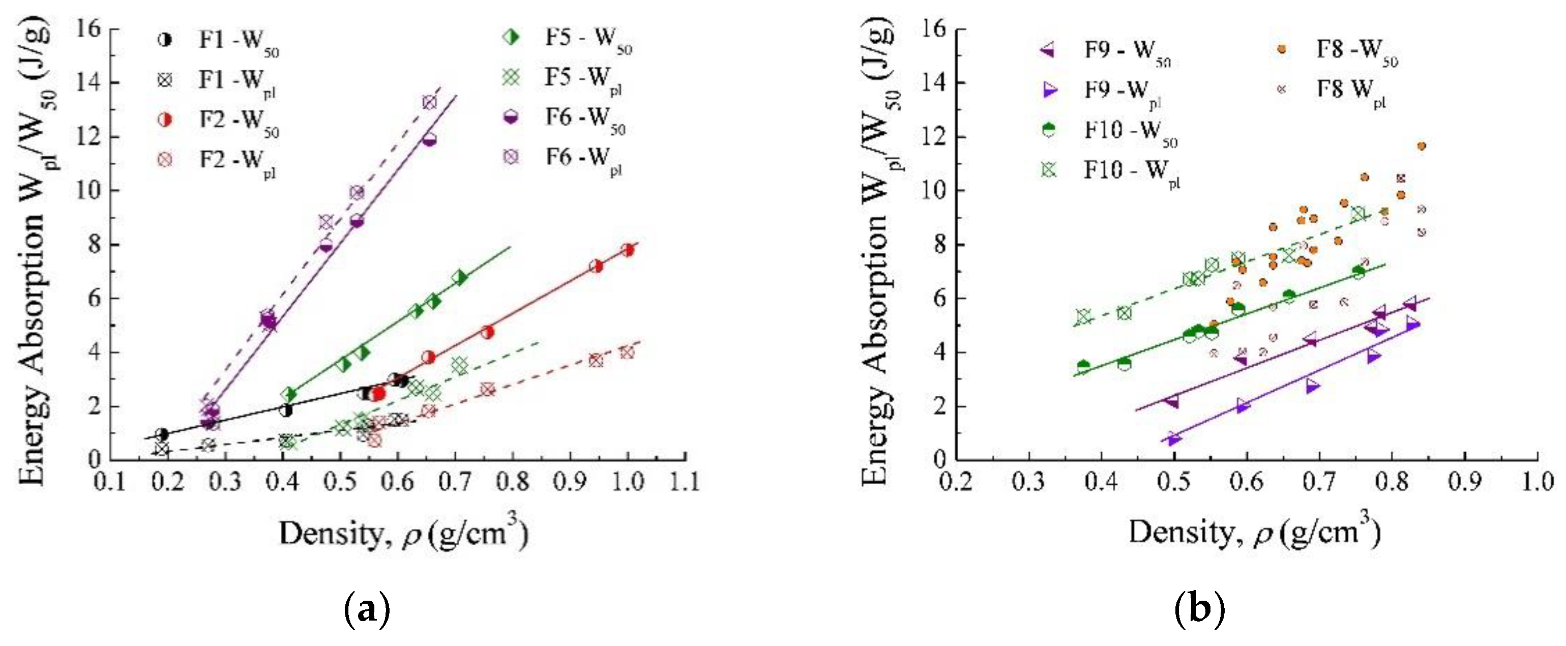
3.3. Energy Absorption Ability of Al-Foam

Indeed, increased energy absorption of aluminum foams can be ensured by the level of plateau stress and/or extension of the plateau regime, both rather depend on the processing variables, including composition of the parent alloy and mechanical properties of the matrix material of the cell walls. In view of this, attention is concentrated on the energy absorption ability of the foams produced with CaCO3 compared to that for the foams processed with TiH2. The data for energy absorption Wpl/W50 being useful for the consideration ability of the foams mentioned above to absorb mechanical energy are presented in Figure 3.
It can be seen in Figure 3a that the slope of the lines is quite different. Energy absorption Wpl/W50 of F1, F5 foams processed with TiH2 decreases gradually as their density, ρ, decreases, although that of F2, F6 foams produced with CaCO3 falls faster. The difference in the micro-mechanism of the deformation attributable to the foregoing foams is the cause of the situation above. In particular, contribution of cell fracture in global collapse is considered to be a distinctive feature for F1, F5 foams, whereas cell collapse by elastic buckling and yielding was found to be preferable for F2 and F6 foams. However, bending and fracture of deformation bands promote strength decrease and, in turn, reducing the energy absorption of the foams when their thickness becomes too small. This becomes especially pronounced when relative density of the foams decreases to a value less than critical one, i.e., ρ/ρs < 0.2.
The question is: why is energy absorption W50 found to be much greater than Wpl for F1, F2, F5, and F9 foams. Explanation of this is unexpected; on the first glance, the phenomenon arises from the facts, which strain at the densification, εd, for the foams mentioned above is less than 50%. At this condition, the value of Wpl is related to the end of the deformation plateau, whereas the value of W50 is found at the densification region. Another was believed to be true when the deformation plateau extended up to densification strain, εd, which is approximately 50% or more. For illustration, the data related to W50/Wpl of the F6 foam produced with CaCO3 could be useful for confirmation of the reasoning above. In fact, the line representing energy absorption W50 lies quite below that corresponding to Wpl, although these lines are found to be very close to one another since the densification strain, εd, is limited to approximately 50, as can be seen in Figure 1a. A relatively short deformation plateau detected for the Al-foam F6 results from the plastic crushing of deformation bands, generating the cell wall buckling, as previously observed in [28].
It is reasonable to analyze the energy absorption ability of F9 and F10 foams processed by using high strength alloy comprising brittle eutectic domains/redundant phases. As evidenced from Figure 3, the relative positions of the lines representing energy absorption Wpl/W50 vs. density for the F9 foam is very similar to those for the F5 foam. However, the distance between the positions of the lines representing Wpl and W50 for the F9 foam is much smaller compared to the F5 foam. In contrast, with this relative position of the lines representing energy absorption Wpl/W50 vs. density for the F10 foam is opposed compared to F9 foam processed by using the same parent alloy. The line representing Wpl lies far above that related to W50. In addition, the energy absorption ability of the F10 foam is considerably greater than that exhibited by the F9 foam, although both foams are based on the same alloy. This is the primary for the reason that the F10 foam demonstrates a much higher compressive strength, σpl, compared to the F9 foam, while both foams show a very similar extension of the deformation plateau. It can be clearly seen by comparing the data relevant for the foams above, which are presented in Figure 1b or Figure 2b.
As previously pointed out in [14] and presently confirmed, the distinctive feature of the F8 foam is a significant scatter of the experimental data referring to energy absorption Wpl/W50. Particles of Al3(ScZr) randomly scattered over the cell wall material were believed to be the reason for the unsteady data. Indeed, this circumstance makes it difficult to compare with each other the data concerning energy absorption Wpl/W50 of F8 and F10 foams despite being produced identically with CaCO3. Taking into account the data shown in Figure 3b, it seems that the F8 foam demonstrates none the less smaller values of energy absorption Wpl than the F10 foam. Figure 4 shows the outcome of the comparative analysis regarding energy absorption ability and its efficiency for the studied foams having comparable ρ/ρs ≈ 0.22. As to precautions, energy absorption Wpl and its efficiency Wefpl are calculated at the end of the deformation plateau to avoid misunderstanding in interpretation of the experimental results.
As evidenced in Figure 4, the foams produced with CaCO3 (F2, F4, F6, F8, F10) show higher values of energy absorption Wpl compared to the foams processed with TiH2 (F1, F3, F5, F7, F9). Compositions of the alloys used for creation of the referred foams are listed in Table 1. At the same time, the values of energy absorption efficiency Wefpl of these foams are found to be different owing to differences in microstructure and the prevailing micro mechanism of the cell collapse. In particular, the highest values of energy absorption Wpl are demonstrated by F6 and F10 foams both produced with CaCO3. Nevertheless, energy absorption efficiency Wefpl displayed by the F10 foam is somewhat greater than that of the F6 foam.

4. Summary

Compressive response and mechanical performance metrics of closed-cell foams based on a wide range of Al alloys and created by melt process being realized with or without Ca as a thickening additive by using either traditional titanium hydride as a gas blowing agent or calcium carbonate as an alternative were compared and discussed, taking into consideration the mechanism of cell collapse, depending on the nature of the cell wall material. It was identified that brittle foreign particles/side reaction products and modified eutectic domains/redundant phases originating in the cell wall material due to the employment of an expensive titanium hydride and Ca additive impair the strength and, as a consequence, capability of foams to absorb mechanical energy irrespective of the used parent alloy. As opposed to this application, the inexpensive calcium carbonate offers incontestable preferences in remaining contamination-free cell wall material, resulting in the improvement of performance metrics, particularly, an increase in foams’ strength and energy absorption capability. So, the implementation in practice foams created by the calcium carbonate gas blowing agent is preferable, especially based on Al-Mg-Si (F6) and high-strength Al-Zn-Mg (F10) parent alloys. However, the selection of the best foamed alloy should be done in proper consideration of particular design, operation conditions, and key properties of the intended part or construction.
The results of the present efforts could be useful for application of Al/Al alloy foams adapted to the design of different engineering constructions.

Author Contributions

Conceptualization, A.B.; data curation, A.B. and S.G.; formal analysis, A.B., S.G. and A.V.; investigation, A.B., S.G., Y.Y. and N.S.; methodology, A.B., S.G. and A.V.; resources, A.V., Y.Y. and N.S.; supervision, A.B.; writing—original draft, A.B.; writing—review and editing, S.G. All authors have read and agreed to the published version of the manuscript.

Funding

This research was funded by the National Academy of Science of Ukraine under the Project No III-3-19.

Institutional Review Board Statement

Not applicable.

Informed Consent Statement

Not applicable.

Data Availability Statement

Not applicable.

Acknowledgments

No individual acknowledgement.

Conflicts of Interest

The authors declare no conflict of interest. The funders had no role in the design of the study; in the collection, analyses, or interpretation of data; in the writing of the manuscript.

References

  1. Gibson, L.J.; Ashby, M.F. Cellular Solids: Structure and Properties; Cambridge University Press: Cambridge, UK, 1997. [Google Scholar]
  2. Ashby, M.F.; Evans, A.G.; Fleck, N.A.; Gibson, L.J.; Hutchinson, J.W.; Wadley, H.N.G. Metal Foams: A Design Guide; Butterworth Heinemann: Boston, MA, USA, 2000; p. 251. [Google Scholar]
  3. Byakova, A.V.; Gnyloskurenko, S.V.; Bezimyanniy, Y.B.; Nakamura, T. Closed-cell aluminum foam of improved sound absorption ability: Manufacture and properties. Metals 2014, 4, 445–454. [Google Scholar] [CrossRef] [Green Version]
  4. Xu, Z.; Hao, H. Electromagnetic interference shielding effectiveness of aluminum foams with different porosity. J. Alloys Compd. 2014, 617, 207–213. [Google Scholar] [CrossRef]
  5. Zhu, X.; Ai, S.; Lu, X.; Ling, X.; Zhu, L.; Liu, B. Thermal conductivity of closed-cell aluminum foam based on the 3D geometrical reconstruction. Int. J. Heat Mass Transf. 2014, 72, 242–249. [Google Scholar] [CrossRef]
  6. Banhart, J. Manufacture, characterisation and application of cellular metals and metal foams. Progr. Mater Sci. 2001, 46, 559–632. [Google Scholar] [CrossRef]
  7. Crupi, V.; Epasto, G.; Guglielmino, E. Impact response of aluminum foam sandwiches for light-weight ship structures. Metals 2011, 1, 98–112. [Google Scholar] [CrossRef] [Green Version]
  8. Palomba, G.; Epasto, G.; Crupi, V. Lightweight sandwich structures for marine applications: A review. Mech. Adv. Mater. Struct. 2021. [Google Scholar] [CrossRef]
  9. Banhart, J.; Seeliger, H.-W. Aluminium foam sandwich panels: Manufacture, metallurgy and applications. Adv. Eng. Mater. 2008, 10, 793–802. [Google Scholar] [CrossRef]
  10. Gama, B.A.; Bogetti, T.A.; Fink, B.K.; Yu, C.-J.; Claar, T.D.; Eifert, H.H.; Gillespie, J.W., Jr. Aluminum foam integral armor: A new dimension of armor design. Compos. Struct. 2001, 52, 381–395. [Google Scholar] [CrossRef]
  11. Schaeffler, P.; Rajner, W.; Claar, D.; Trendelenburg, T.; Nishimura, H. Production, Properties, and Applications of Alulight® Closed-Cell Aluminum Foams. In Proceedings of the Fifth International Workshop on Advanced Manufacturing Technologies, London, ON, Canada, 16–18 May 2005. [Google Scholar]
  12. Banhart, J. Light-metal foams-history of innovation and technological challenges. Adv. Eng. Mater. 2013, 15, 82–111. [Google Scholar] [CrossRef]
  13. Gibson, L.J. Mechanical behavior of metallic foams. Annu. Rev. Mater. Sci. 2000, 30, 191. [Google Scholar] [CrossRef]
  14. Nakamura, T.; Gnyloskurenko, S.V.; Sakamoto, K.; Byakova, A.V.; Ishikawa, R. Development of New Foaming Agent for Metal Foam. Mater. Trans. 2002, 43, 1191–1196. [Google Scholar] [CrossRef] [Green Version]
  15. Byakova, A.V.; Gnyloskurenko, S.V.; Sirko, A.I.; Milman, Y.V.; Nakamura, T. The role of foaming agent in structure and mechanical performance of Al based foams. Mater. Trans. 2006, 47, 2131–2136. [Google Scholar] [CrossRef] [Green Version]
  16. Byakova, A.V.; Sirko, A.I.; Mykhalenkov, K.V.; Milman, Y.V.; Gnyloskurenko, S.V.; Nakamura, T. Improvements in stabilisation and cellular structure of Al based foams with novel carbonate foaming agent. High Temp. Mater. Processes 2007, 26, 239–246. [Google Scholar] [CrossRef]
  17. Yu, S.R.; Luo, Y.R.; Liu, J.A. Effects of strain rate and SiC particle on the compressive property of SiCp/AlSi9Mg composite foams. Mater. Sci. Eng. A 2008, 487, 394–399. [Google Scholar] [CrossRef]
  18. Zhao, W.M.; Zhang, H.; Li, H.P. Study on Fabrication, Defects and Compression Properties of Al Foams at Different Foaming Temperatures. Adv. Mater. Res. 2011, 214, 70–74. [Google Scholar] [CrossRef]
  19. Byakova, A.V.; Vlasov, A.A.; Gnyloskurenko, S.V.; Kartuzov, I. Method for Making the Blocks of Foamed Aluminum/Aluminum Alloys. UA Patent No. 104367, 27 January 2014. [Google Scholar]
  20. Kumar, S.; Pandey, O.P. Role of fine size zircon sand ceramic particle on controlling the cell morphology of aluminum composite foams. J. Manuf. Proc. 2015, 3, 172–180. [Google Scholar] [CrossRef]
  21. Nava, M.G.; Cruz-Ramírez, A.; Rosales, M.Á.; Gutiérrez-Pérez, V.H.; Sánchez-Martínez, A. Fabrication of aluminum alloy foams by using alternative thickening agents via melt route. J. Alloys Compd. 2017, 698, 1009–1017. [Google Scholar] [CrossRef]
  22. Sutarno, S.; Nugraha, B.; Kusharjanto. Optimization of calcium carbonate content on synthesis of aluminum foam and its compressive strength characteristic. AIP Conf. Proc. 2017, 1805, 060003. [Google Scholar]
  23. Heidari Ghaleh, M.; Ehsani, N.; Baharvandi, H.R. Compressive Properties of A356 Closed-Cell Aluminum Foamed with a CaCO3 Foaming Agent Without Stabilizer Particles. Met. Mater. Int. 2020, 27, 3856–3861. [Google Scholar] [CrossRef]
  24. Byakova, A.; Kartuzov, I.; Gnyloskurenko, S.; Nakamura, T. The Role of Foaming Agent and Processing Route in Mechanical Performance of Fabricated Aluminum Foams. Procedia Mater. Sci. 2014, 4, 104–109. [Google Scholar] [CrossRef] [Green Version]
  25. Gnyloskurenko, S.; Nakamura, T.; Byakova, A.; Podrezov, Y.; Ishikawa, R.; Maeda, M. Development of Lightweght Al alloy and Technique. Can. Metall. Q. 2005, 44, 7–12. [Google Scholar] [CrossRef]
  26. Milman, Y.V.; Byakova, A.V.; Sirko, A.I.; Gnyloskurenko, S.V.; Nakamura, T. Improvement of structure and deformation behavior of high-strength Al-Zn-Mg foams. Mater. Sci. Forum 2006, 519–521, 573–578. [Google Scholar] [CrossRef]
  27. Gnyloskurenko, S.V.; Byakova, A.V.; Sirko, A.I.; Dudnyk, A.O.; Milman, Y.V.; Nakamura, T. Advanced Structure and Deformation Pattern of Al-based Alloys with Calcium Carbonate Agent. In Porous Metals and Metallic Foams; Lefebvre, L.P., Banhart, J., Dunand, D.C., Eds.; DEStech Publications, Inc.: Lancaster, PA, USA, 2008; pp. 399–402. [Google Scholar]
  28. Byakova, A.V.; Gnyloskurenko, S.V.; Vlasov, A.N.; Semenov, N.M.; Yevych, Y.M.; Zatsarna, O.V.; Danilyuk, V.M. Effect of Cell Wall Ductility and Toughness on Compressive Response and Strain Rate Sensitivity of Aluminium Foam. Adv. Mater. Sci. Eng. 2019, 2019, 3474656. [Google Scholar] [CrossRef] [Green Version]
  29. Kriszt, B.; Foroughi, K.; Faure, H.P. Degischer, Behaviour of aluminium foam under uniaxial compression. Mater. Sci. Technol. 2000, 16, 792–796. [Google Scholar] [CrossRef]
  30. Markaki, A.E.; Clyne, T.W. The effect of cell wall microstructure on the deformation and fracture of aluminum-based foams. Acta Mater. 2001, 49, 1677–1686. [Google Scholar] [CrossRef]
Figure 1. Compression curves for F1, F3, F5, F7, F9 foams processed with titanium hydride TiH2 and F2, F4, F6, F8, F10 foams produced with calcium carbonate CaCO3, all performed with different parent alloys, such as (a) pure Al (F1, F2), Al-Si alloy (F3, F4), Al-Mg-Si alloy (F5, F6) and (b) Al-Zn-Mg (Sc,Zr) (F7, F8), Al-Zn-Mg (F9, F10).
Metals 12 01384 g001
Figure 2. Relative compressive strength, σpl/σys, dependences on the relative density, ρ/ρs, for the foams produced with TiH2 (F1, F3, F5, F7, F9) and CaCO3 (F2, F4, F6, F8, F10), which are performed with various parent alloys: (a) Al (F1, F2), Al-Si, (F3, F4), Al-Mg-Si (F5, F6) and (b) Al-Zn-Mg (Sc,Zr) (F7, F8), Al-Zn-Mg (F9, F10).
Metals 12 01384 g002
Figure 3. Energy absorption Wpl/W50 vs. density for the foams processed with TiH2 (F1, F5, F9) and those produced with CaCO3 (F2, F6, F8, F10), which are performed with various alloys, such as (a) Al (F1, F2), Al-Mg-Si (F5, F6) and (b) Al-Zn-Mg (Sc,Zr) (F8), Al-Zn-Mg (F9, F10).
Metals 12 01384 g003
Figure 4. Basic data for (a) energy absorption ability Wpl and (b) its efficiency Wefpl for the foams processed with TiH2 (F1, F3, F5, F7, F9) and CaCO3 (F2, F4, F6, F8, F10) performed at the comparable ρ/ρs ≈ 0.22.
Metals 12 01384 g004
Table 1. Specification of the aluminum foams created via melt process.
Foam CodeParent Alloy and Processing Additives, (wt.%)Microstructure of the Cell Wall MaterialContaminating Side ProductsSolid Yield Strength,
σys (MPa)
F1Al + 1TiH2 + 1Caα-Al + E (Al + Al3Ti + Al4Ca)Particles: TiH2/
TiAl3/TiAl2
42.8 ± 4.89
F2Al + 2CaCO3 + 1Caα-Al + E (Al + Al4Ca)Fine particles CaO43.5 ± 7.12
F3Al-7Si + 1.5TiH2 + 1Caα-Al (Ti) + E (Al-Si)Particles: TiH2/
TiAl3, Al3Ti (Si), Al2CaSi2
220 ± 20.54
F4Al-7Si + 2CaCO3α-Al + E (Al-Si)Fine particles CaO140 ± 15.67
F5Al-1Mg-0.6Si + 1.5TiH2 + 1Caα-Al (Ti) +
E (Al + Mg2Si + S(Al2CuMg) + CuAl2) + E (α-Al + Al4Ca+ Al2CaSi2 + Al4CaCu + Al3Ti)
Particles: TiH2/
TiAl3, Al3Ti
124 ± 14.82
F6Al-1Mg-0.6Si + 2CaCO3α-Al + E {α-Al + CuAl2}, α-Al + E {α-Al + S(Al2CuMg)},
α-Al + E {α-Al + Mg2Si}
Fine particles CaO105 ± 7.25
F7Al-5.5Zn-3.0Mg (Sc,Zr)+ 1.5TiH2 + 1Caα-Al(Ti) + T(AlCuMgZnCaTi)Particles: TiH2/
TiAl3, Al3(ScZr)
200 ± 28.24
F8Al-5.5Zn-3.0Mg (Sc,Zr) + 2CaCO3α-Al + T(AlCuMgZn)Particles Al3(ScZr)
Fine particles CaO
213 ± 15.14
F9Al-6Zn-2.3Mg + 1.5TiH2 + 1Caα-Al(Ti) + T(AlCuMgZnCaTi)/
M(AlCuMgZnCaTi)/S
(CuMgAl2CaTi)
Particles: TiH2/
TiAl3
220 ± 15.00
F10Al-6Zn-2.3Mg + 2CaCO3α-Al + T(AlCuMgZn)/
M(AlCuMgZn)/S(CuMgAl2)
Fine particles CaO252 ± 10.15
Publisher’s Note: MDPI stays neutral with regard to jurisdictional claims in published maps and institutional affiliations.

