1. Introduction
Gears are among the most important components of mechanical systems for power transmission. The main design trend of gear transmission systems is to maintain a high-load and high-speed operation capacity to ensure a light weight [
1,
2,
3,
4,
5]. The failure of key components, such as gears, in the transmission chain, results in the breakdown of the entire system. Substantial effort has been made to enhance the endurance of gears in different types of failure. There are two methods to extend the service life of gears. One is to enhance the strength of the material used for gear manufacturing, and the other is to reduce the stress that it endures [
3,
4,
5].
Many factors, including material properties, working conditions, and stress state, can influence the occurrence of different gear-failure modes [
3,
4]. Despite many techniques such as case hardening (including carburization and nitridation, surface finishing, and profile modification), the most frequent failures, especially pitting, micropitting, and flank fracture, cannot be avoided. High-performance alloy steel with a surface case-hardening process is the basic requirement for gears in transmission systems such as those for wind turbines, ships, automobiles, and helicopters [
3,
6]. Moreover, different terminal processes are adopted according to the design requirements and process conditions to improve the service properties by prolonging the fatigue life of gears [
6,
7,
8]. However, gear failure cannot be avoided.
Pitting caused by rolling contact fatigue (RCF) is one of the most common failure modes of gears, and numerous studies have been conducted on the formation mechanisms and prevention methods for reducing pitting occurrence. Mallipeddi [
8] studied the micropitting of gears with different surface integrity in hardened cases and found that its failure was due to surface-contact fatigue. Sekercioglu et al. [
9] studied the pitting failure of truck spiral bevel gears and found that a low surface hardness and high pressure owing to poor surface conditions were the main reasons for the failure. Watanabe [
3] investigated the effect of surface-heat treatments and material design on increasing the resistance ability of surface pitting and proposed a technique combining carbo-nitriding with shot peening to improve the contact-fatigue endurance. Dimitrov et al. [
10] evaluated and predicted the fatigue-crack initiation, propagation direction, and rate of high-strength steel gears subjected to shot peening; they found that the residual stress induced by the shot-peening process can extend the service life of gears. These studies mostly investigated methods for extending the service life of gears by improving the strength of the material.
Several studies have also investigated factors such as surface quality that influence the contact fatigue of gears from other perspectives [
11,
12,
13,
14]. Bergstedt et al. [
13] studied the influence of surface roughness on the pitting and micropitting life of gears and found that a smooth gear surface can reduce micropitting damage and prolong the pitting life. Krantz [
14] studied the effect of roughness on gear-surface fatigue and found that super-finishing of gears can provide significantly longer lives to ground gears. Qi et al. [
15] studied the contact fatigue of gears based on a fractal contact model and illustrated the influence of various factors on the contact strength of gears. Heli et al. [
16] studied the contact fatigue of a wind-turbine gear pair considering the surface roughness and found that the surface roughness significantly increases the contact-fatigue failure risk within a shallow area.
These studies aimed to identify the effect of different factors on the pitting-formation mechanisms and methods to extend the service life of gears [
1,
5,
6,
7,
8,
9,
10]. Several studies have focused on the influence of surface quality on pitting failure resulting from contact fatigue [
1,
3,
7,
8,
10]. However, few have focused on the mechanism of the formation of different pitting morphologies on the gear surface, particularly the inherent relationship between pitting morphologies and differences in service life and the factors responsible for them under various terminal machined processes.
To analyze the influence of different machining processes on the service life and pitting morphology characteristics, this study used a contact-fatigue test of gears machined using grinding and surface-finishing processes. The microgeometry, roughness parameters, and residual stress of the gear surfaces machined using the different processes were measured. The rough surfaces, considering the microgeometry feature around a pitch based on microgeometry and roughness parameters measured from gear surfaces machined with different process lines, were reconstructed with a fractal model to analyze the contact-stress distribution. The differences between the pitting morphology features formed owing to contact fatigue on the two types of gears are analyzed, and suggestions are proposed for improving the pitting resistance of gears.
2. Experimental Methods and Results
With the increasing performance demand on gear transmission systems from different areas, various processes have been adopted to improve the micropitting resistance of the gear-tooth surface. Barrel finishing is one of the most commonly used terminal processes in gear manufacturing. Although various tests and applications have verified the excellent pitting resistance of surfaces machined by different super-finishing processes over those machined by traditional grinding processes, the occurrence of pitting cannot be completely avoided. In addition, little attention has been paid to the features of different pitting morphologies resulting from contact fatigue of gear surfaces machined with different processes and the relationship between a specific pitting morphology and microgeometry formed by different processes.
Two groups of gears made of 18CrNiMo7 steel and manufactured using different terminal machining processes were tested on a contact-fatigue test bench to compare the property differences. The basic parameters of the gears used for the testing are listed in
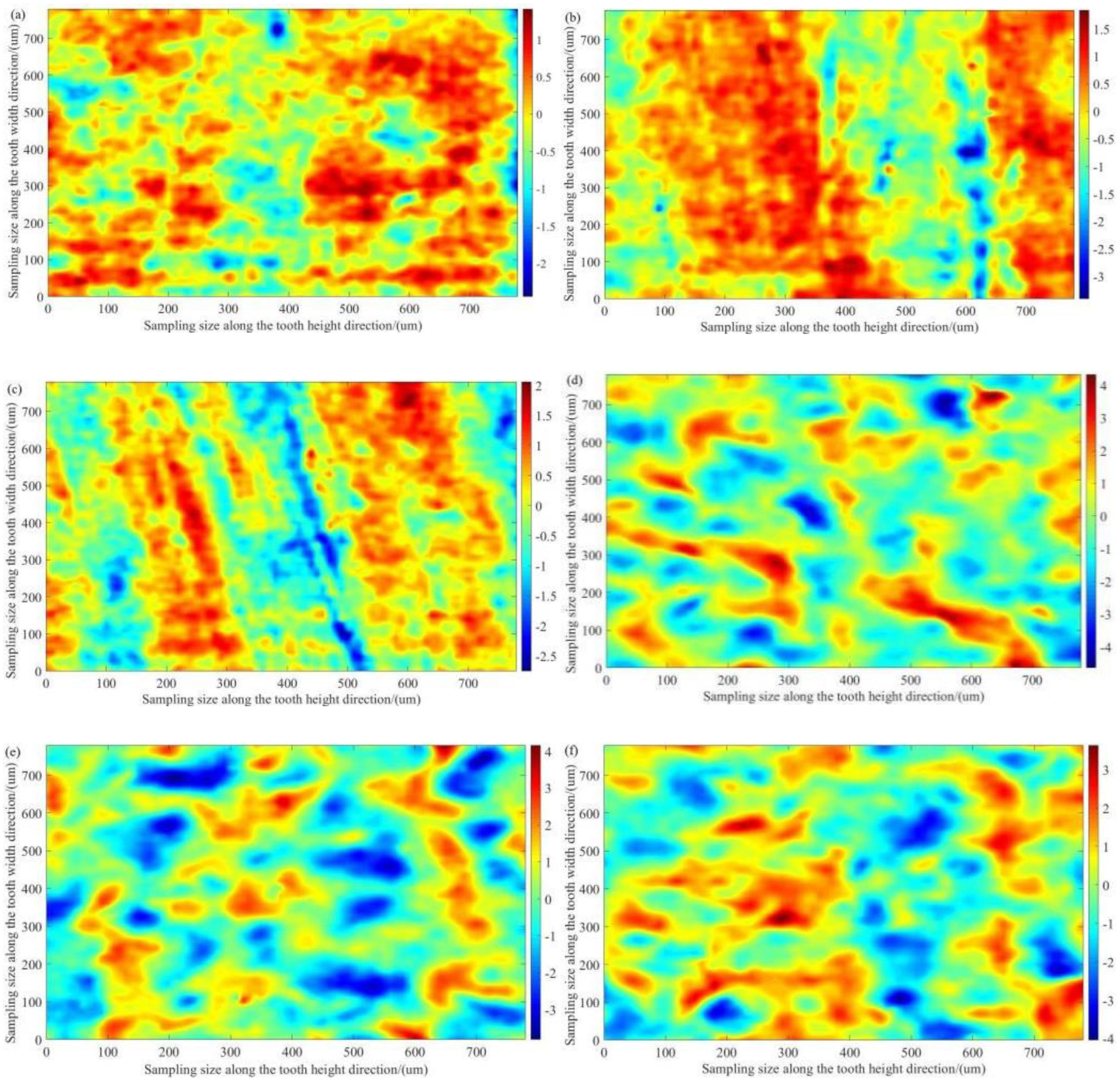
Table 1. One group was manufactured by sequential processing, including forging, rough turning, tempering, semi-extractive turning, hobbing, cemented quenching, shot peening, finish turning, and grinding. The other group was barrel-finished after the grinding process. Before the fatigue test, the surface roughness of the two groups of gears was measured using a noncontact profilometer (Nanovea JR25 3D) according to ASME B46.1-2019. The microgeometry morphology captured from the surface around the pitch line of the two gear groups is shown in
Figure 1, and their key roughness parameters are listed in
Table 2 for reconstructing the microscopic geometry of the surface.
Figure 1a–c show that the grinding marks of the gear machined using barrel finishing are flattened, and the distribution of peaks and valleys is anisotropic. The geometry morphology captured from the gears machined using grinding shows evident grinding tracks along the width direction of the tooth on the gear surface (
Figure 1d–f). The height of the peaks and depth of the valleys formed by grinding were evidently larger than those formed by barrel finishing.
The residual stress distribution in the middle of the gear tooth with different machining processes was measured using an X-ray stress analyzer (Proto-LXRD). The results are shown in
Table 3. The residual stress level of the gear tooth with the barrel finishing process was obviously lower than that with the grinding process.
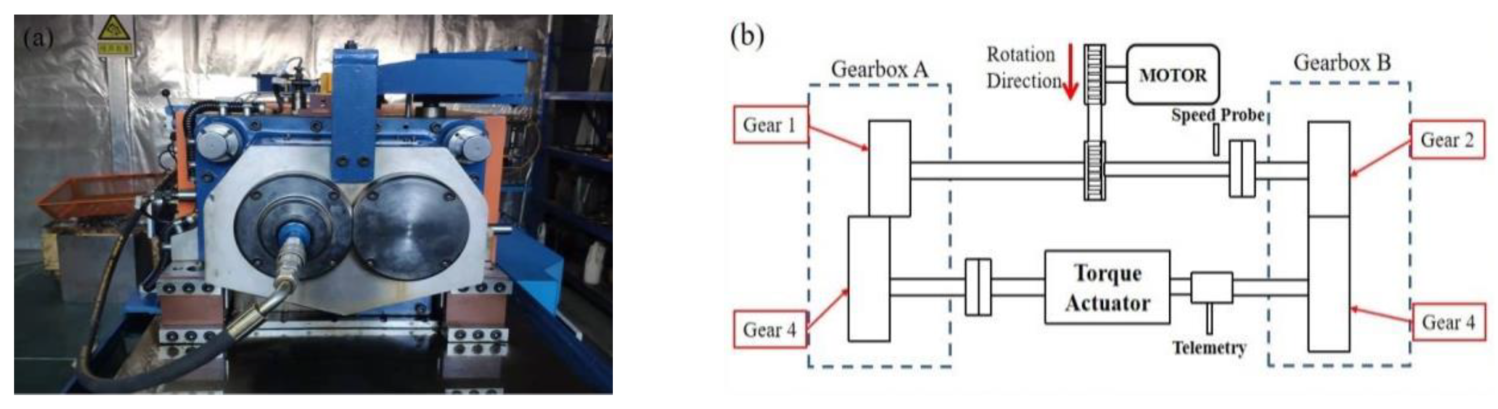
Subsequently, the contact-fatigue test was performed on a closed power-flow test bench (shown in
Figure 2) under a constant torque of 1.115 kN·m with a rotation speed of up to 1200 r/min. The gears were lubricated with gear oil (L-CKC 320).
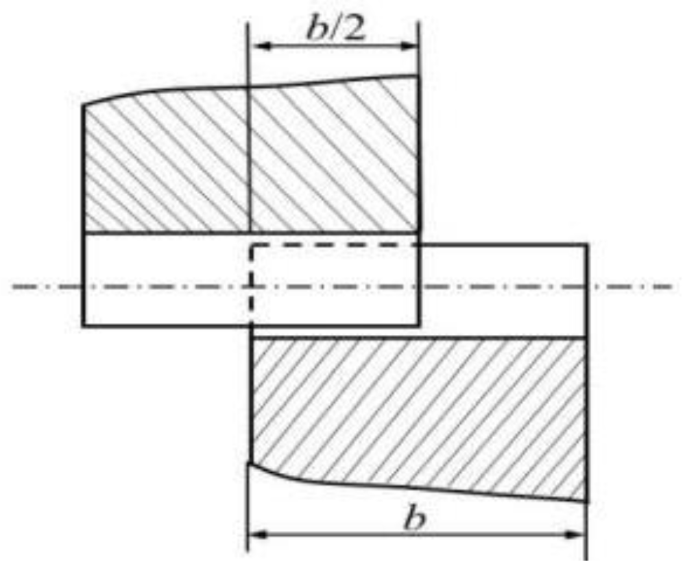
The gear pair was set in a staggered lap-meshing mode, as shown in
Figure 3, which can obtain higher contact stress by loading a relatively small torque. The test was stopped when the pitting area reached 0.4% of the total working area of a single tooth surface. The stress cycling numbers of the tested gears were recorded and are listed in
Table 4. The results reveal that the life of the gears with surface finishing is approximately five times longer than that of the gears machined by grinding.
After contact-fatigue testing, the surfaces of the gear teeth were cleaned with alcohol using an ultrasonic cleaning machine, and their morphologies were visually inspected. Different pitting-corrosion distribution characteristics were observed on the tooth surfaces of the two groups of gears.
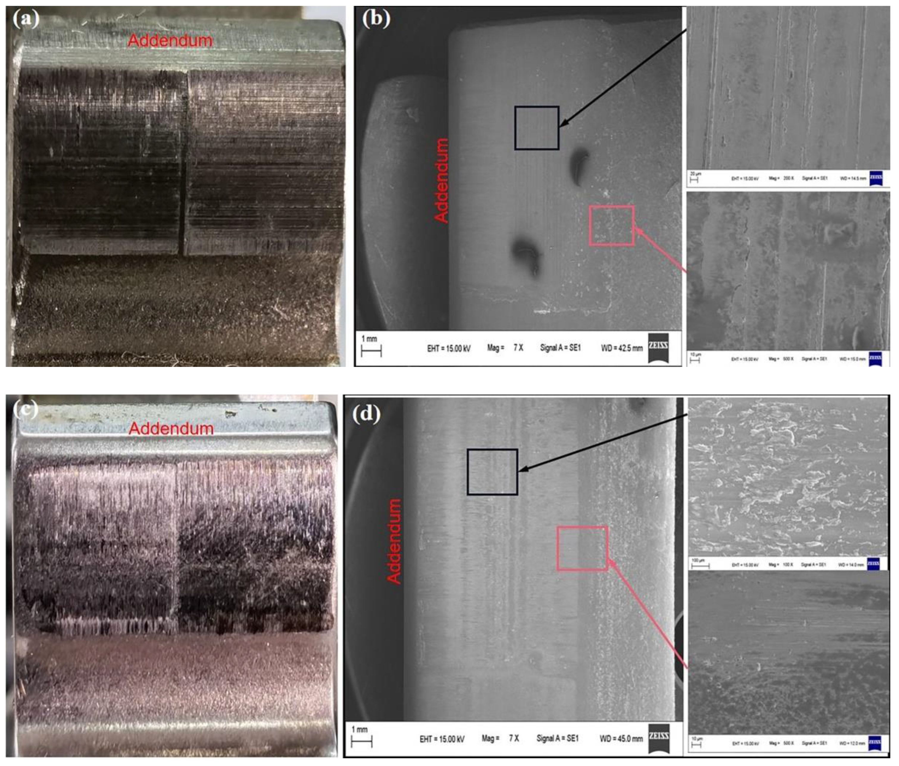
Figure 4a,b show the macroscopic photographs and scanning electron microscopy (SEM) images of an entire tooth face captured from the gears during the grinding process after the fatigue test. There are conspicuous scuffing marks on the surface close to the addendum of the gear surface as well as the pitting morphology formed at the bottom of the grinding marks in the middle of the surface and areas close to the root side of the pitch line (
Figure 4a). Grinding marks along the width direction of the gear tooth are also evident in
Figure 4a. Examination of the middle and surrounding areas of the pitch line by SEM shows that pit etching is mostly located along the grinding marks (shown in
Figure 4b, captured from the area enclosed by the black square). The amplification images captured from the area around the pitch line and the middle area of the tooth surface show that pitting cracks are mostly initiated at the bottom of the valleys formed by grinding, and the propagation direction is perpendicular to the grinding marks (shown in
Figure 4b, captured from the area enclosed by the black and red squares).
Figure 4c,d show the macroscopic photographs and SEM images obtained from the surface of the gear using barrel finishing after the contact-fatigue test. In
Figure 4c, there are no evident grinding marks left owing to barrel finishing. Scuffing marks are noticeable at the addendum of the gear surface. Small pit etchings located in the middle part of the gear surface and areas around the pitch line are observed. The pit-etching morphology formed by the contact fatigue on the gear surface machined using barrel finishing is significantly different from that shown in
Figure 4a,b of the grinding surface. The pit-etching sites are randomly distributed on the barrel-finishing surface, and the propagation direction is perpendicular to the width direction of the tooth.
Contact Stress of the Gear Surface Considering Microgeometry
To further analyze the features of the pitting morphology on different gear surfaces, the contact-stress distribution is analyzed in this section. According to [
17,
18,
19], surface morphologies with different features can be formed using different manufacturing processes. The roughness of the surface formed by various processing techniques influences the pressure fluctuation and can further affect the fatigue of the gear pair during meshing. In general applications, grinding is the last process of gear machining that can satisfy most application requirements. For some areas that require a high quality, lower noise, and longer life of the gear transmission system, surface finishing is adopted to improve the gear properties and satisfy various demands. Barrel finishing is one of the most commonly used processes for gear-surface finishing, owing to its low cost. As mentioned in the previous section, two groups of gears machined by grinding and combining processes with grinding and barrel finishing were tested. The micromorphology and roughness parameters around the pitch line of the two types of gear surfaces were measured using a nanoveaJR25 3D noncontact profilometer before the contact-fatigue test.
Based on the microgeometry morphology measured from the area around the pitch line of the two groups of gears, the microgeometry around the pitch line of the gear surfaces was reconstructed using the fractal method to analyze the contact stress and bearing ability difference of the two groups of gears. A random non-Gaussian surface representing the height values of a three-dimensional (3D) rough surface can be generated based on the roughness parameters [
17,
18,
19]. Therefore, the roughness geometry of the gear surface before the fatigue test was generated and represented by an N × M matrix
z(
i,
j), expressed as Equation (1) below [
17,
18,
19]:
where
z(
i,
j) is an
M ×
N matrix representing the roughness amplitudes of the surface;
m = M/2;
n = N/2;
h(
k,
l) is a digital filter function; and
η′(
k,
l) is a non-Gaussian random series generated by Johnson translation from the Gaussian input sequence
η(
k,
l) generated by a random number generator.
Subsequently, the essential equations for contacting a gear pair can be established by simplifying the gear pair to two cylinders with a radius equal to the circular arc radius of the tooth profile. The pitting resulting from contact fatigue was primarily evaluated at the lower-side position of the pitch line because of the more pronounced stress concentration when the gears were engaged at the pitch point, compared to the other meshing positions. Therefore, the contact between the gear pair at the pitch point can be simplified as a circle with an equivalent curvature and radial ρ = ρ1ρ2/(ρ1 + ρ2) in contact with an infinite elastic half-space.
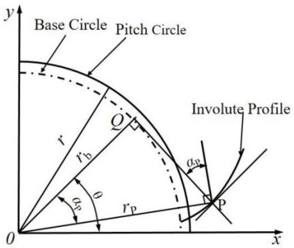
Figure 5 depicts the geometrical relationships of the different gear parameters. Based on the geometrical relationship, the curvature radial
ρ of the tooth profile at the pitch point can be expressed as Equation (2):
where
r is the indexing-wheel radial of the gear, which is equal to the radial of the pitch circle when the engaged gear pairs with the standard parameters and center distance;
is the distance between the pitch point and gear-wheel center;
rb is the radial of the base circle;
ρ is the radial curvature of the involution tooth profile at the pitch point; and
α and
αP are the pressure angles of the indexing circle and pitch point
P during gear meshing, respectively.
Therefore, a surface with microgeometry around the pitch line of the gear can be constructed by superimposing the rough surface generated by the fractal method on the surface with a radial gear profile equivalent to the profile of the pitch point. The contact stress can then be computed based on previously reported models of rough contact using the conjugate gradient method [
20,
21,
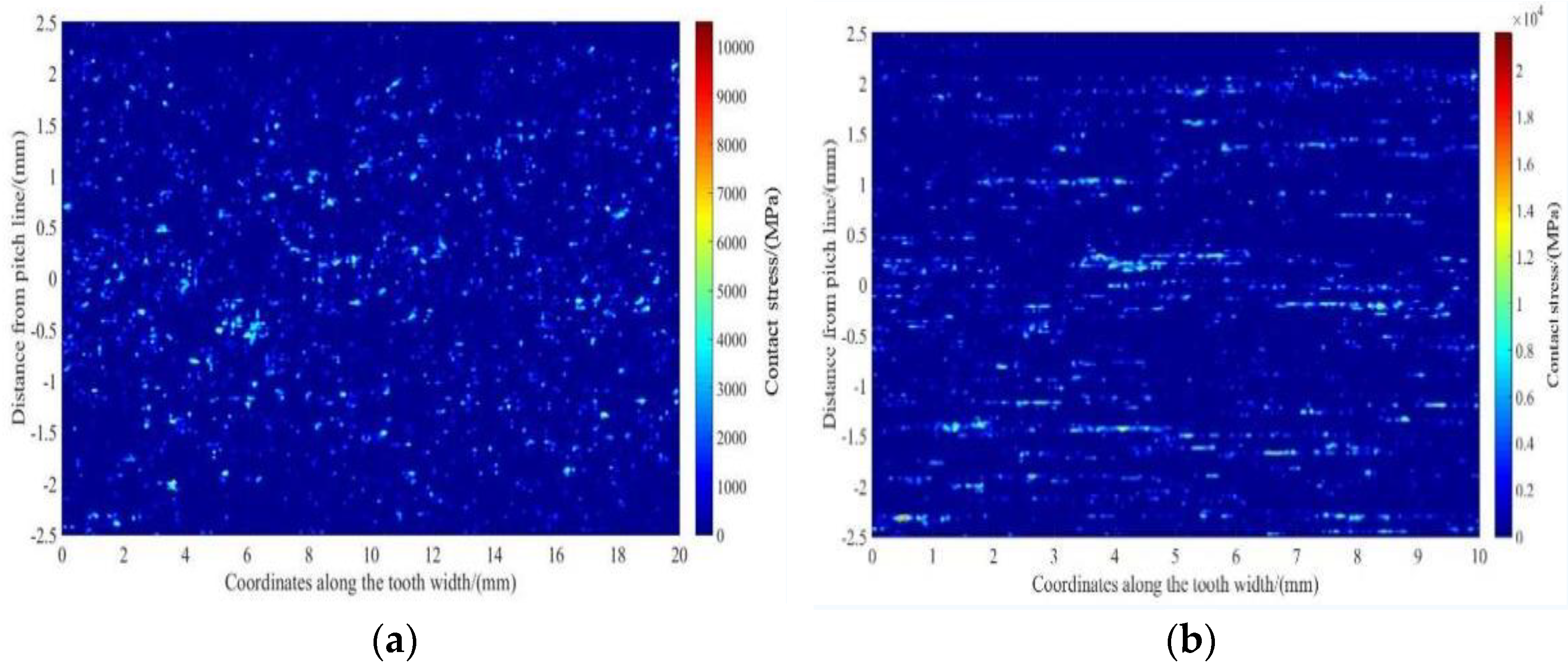
22]. For the two types of gears with different machining processes, the contact-stress distribution around the pitch line using the equivalent model is shown in
Figure 6. The stress distribution shown in
Figure 6 was computed based on the simplified contact between two cylinders with radials equal to the radial curvature of the involution tooth profile at the pitch point with a load F ≈ 10,000 N.
Figure 6a reveals that the contact stress was randomly distributed owing to the micromorphology, with a maximum of approximately 12,000 MPa.
Figure 6b shows a distinct distribution feature coinciding with the grinding marks along the width of the tooth. The maximum stress level of the gear surface machined using the grinding process was approximately 20,000 MPa, which was significantly higher than that machined using the finishing surface.
3. Discussion
Different roughness values can be obtained on the machined surface using various machining technologies. Grinding is the principal method that guarantees the precision and quality of gears used in high-precision mechanical drives. With the increasing demand for high-power-density gear transmission systems, different methods such as surface hardening, profile, and surface morphology optimization have been adopted.
Along with the gradual maturation of gear-surface strengthening technology and tooth-profile optimization, applications of this process in actual production are increasingly common. Moreover, the significant effect of the roughness of the gear surface on the quality of the lubricating effect, and thus the conditions of the scuffing and pitting endurance, make ultraprecision machining processes increasingly important. Various surface-finishing processes have been adopted to further improve the service performance of gears. Barrel finishing is a cost-efficient process. Commonly, the roughness of the gear surface can be reduced to Ra 0.2–0.4 by the barrel-finishing process from the original roughness (Ra 0.8–1.2).
The service life of gears machined using the super-finishing process is verified to be longer than that of traditional gears, such as those machined using the grinding process. As shown in the test results of this study, the service life of gears machined using the finishing process is approximately 5–7 times that of those machined with the grinding process. According to [
4] and the international technique report ISO/TR 15144:2018 [
23], the micropitting load capacity of a gear can be represented by a safety factor S
λ based on the specific film thickness
λ [
23]:
where
λmin denotes the minimum specific lubricant film thickness in the contact area;
λP is the permissible specific lubricant film thickness;
Sλ,min represents the minimum required safety factor;
h0 is the lubricant film thickness, with the assumption that the contact surface is smooth; and
is the combined root-mean-square (RMS; usually,
Rq can be replaced by the effective arithmetic mean roughness value
Ra).
From prior studies [
6,
24], the risk of micropitting increases with decreasing values of
Sλ. When the geometry and running parameters were determined,
λP and
h0 were constant. Thus, the value of the safety factor is significantly dependent on the minimum lubricant film thickness,
λmin. This implies that the higher the roughness level, the smaller the minimum specific lubricant film thickness and the higher the risk of micropitting. The roughness parameter,
Rq, of the gears in this study was measured, as shown in
Table 2. Based on the roughness values listed in
Table 2, the pitting risk of gears machined using the grinding process is approximately two or more times that of gears machined using the finishing process. The service life of the grinding-process gears is evidently shorter than that of the finishing-process gears, which corresponds to the test results in this study. Similar results have been reported [
15,
16], wherein the authors concluded that super-finishing can effectively modify the surface topographies and subsequently reduce the surface-initiating failure risk, thereby extending the fatigue life of the component.
Moreover, the index of contact fatigue failure risk can be calculated as follows [
6]:
where
R is the risk of gear contact fatigue failure;
is the Dang Van equivalent stress, which can be deduced from the multi-axial stress history during the loading process;
is the fully reversed torsion fatigue limit;
is the maximum shear stress;
is the hydrostatic stress; and
is the residual stress.
According to Equation (5) and the residual stress measured from the gear teeth with different machining processes, as shown in
Table 2, the failure risk of gears machined using the finishing process can be obviously decreased relative to those using the grinding process.
The different micropitting morphologies shown in
Figure 4 reveal evident morphological correlations. In this study, the contact-stress levels, considering the microgeometry formed by different terminal processes, are evidently different, as shown in
Figure 6. As shown in
Figure 6, the maximum stress resulting from the micro-peaks is 10,000–20,000 MPa, which is approximately 5–10 times that resulting from the contact between smooth surfaces. The higher stress level at the peaks of the microgeometry causes the cracks to preferentially initiate and propagate (comparing
Figure 4 and
Figure 6). Moreover, the micropitting formed because of the contact fatigue of the finishing surface is anisotropically distributed (
Figure 4d), and the propagation direction is perpendicular to the width direction of the tooth. The pitting topographies of the grinding surface indicated that the cracks are mostly initiated at the root of the grinding marks (
Figure 4b). The contact stress of the finished surfaces reconstructed based on the roughness parameters shows an anisotropic distribution feature. The stress peaks, which are consistent with the strike of the grinding marks on the grinding surface, are consistent with the pitting distribution (comparing
Figure 4 and
Figure 6b). Therefore, the different presence of micropitting formed on the two types of gears studied is mostly due to the surface stress and inherently due to the microtopographic features formed by the machining process. This is consistent with previous results [
6,
23,
24,
25], which stated that micropitting could be formed along the surface-roughness asperities.


 ,
, 


