Abstract
When a railway vehicle moves on a curved rail, sliding contact between the rail head side and wheel flange causes wear on the wheel flange. Traditionally, a wheel with thinned flange is machined to get a minimum flange thickness specified for structural safety. This operation reduces the rim thickness and shortens the life of the wheel. In the present study, the thinned flanges were hard-faced by submerged arc welding. A welding wire, which has good weldability to the base material of the wheel and does not generate thermal cracking, was developed. The effects of welding polarity on the microstructure, hardness, friction coefficient, and wear characteristics of the welded wheel were studied. The hardness of the wheel welded with reverse polarity was similar to that of welded with straight polarity. The wear rates of the wheel disc welded with reverse polarity and its counterpart rail disc were 11% and 27% lower than those welded with straight polarity. Delamination wear due to subsurface crack propagation and oxidation wear were mixed. The hardness of the rail before the wear test was in the range of 250–300 HV. After the wear test, it soared to 500 HV.
1. Introduction
Hardfacing has been widely used in industry to extend the lifetime of worn-out parts and to protect the wear of machine parts such as chisel plowshare [1], valve seat ring [2], pipeline valves [3], excavator teeth [4,5], turbine blades [6,7], casting roller [8], coal crusher [9], crane wheels [10,11], railway wheels [12,13], etc. Overlay welding and laser cladding are useful for hardfacing. Laser cladding uses a high-power laser as a heat source to melt and attach metal powder to a base metal. Laser cladding has been applied to improve the hardness of metal surfaces [14,15], corrosion resistance [16,17,18], and abrasion resistance [19,20]. Additive manufacturing by laser cladding has the advantages of robust bonding with the matrix, small heat-affected zone, and fine microstructures. However, it has not yet been utilized for parts such as railroad wheels subjected to high contact stress of more than 1000 MPa and toughness of about 100 MPa.
Overlay welding includes plasma transfer arc welding, gas metal arc welding (SMAW), laser beam welding, and submerged arc welding (SAW) [21]. Zahiri [22] hard-faced ferroalloy powder mixtures to mild steel by submerged arc welding. He claimed that the Ni and Si components improve the toughness of the weldment and suppress crack formation in the joint with the base metal. Öteyaka and Arslan [23] hard-faced AISI 1030, 1040, and 1050 steel surfaces with plasma transfer arc and shielded metal arc welding to improve wear and corrosion resistance. SiC+B4C coating by plasma transfer arc welding gave the materials a good corrosion resistance. Günther et al. [24] performed FeCrC hardfacing with gas metal arc welding to improve the wear resistance of materials for mining and drilling. They presented a method to independently control the dilution and microstructure using a hot wire in addition to the welding electrode and showed that this method improves the wear resistance compared to single-layer GMAW. Existing studies on steel wheel hardfacing of tracked vehicles closely related to this study are as follows. Malinov et al. [10] reconditioned worn crane wheels by welding and obtained weld metal containing austenite reinforced with carbide. The weld metal showed a self-quenching effect by martensitic transformation under service loading. Anan’ev et al. [11] investigated the effect of welding wire on microstructures and the wear resistance of hard-faced crane wheels.
Figure 1 shows the wheel of a train with a worn flange. Figure 2 shows schematically overlay welding of the worn flange and reprofiling of the wheel with flange wear of 10 mm and tread wear of 9 mm. The minimum flange thickness satisfying the wheel management regulations is about 22 mm. The machining depth of the wheel tread required to secure the minimum flange thickness on the worn wheel is 25 mm. If the worn flange got welded as shown in Figure 2, the depth of tread machining required to restore the flange shape is 1 mm. Therefore, the saved wheel radius due to welding is 24 mm, which can extend the life of the wheel a lot. The production of one wheel weighing 150 kg emits about 1.75 tons of carbon dioxide; and it is estimated that there are more than 10 million wheels on railroad cars worldwide. Therefore, extending the life of the wheel can greatly contribute to reducing carbon dioxide emissions. Two basic material requirements for railway wheels and rails are wear resistance and rolling contact fatigue resistance. In general, these properties are incompatible with each other. Conventionally railway wheels and rails are made of ferritic-pearlitic alloys. Although they have many merits like low cost, wear resistance, good weldability, easy production, etc., improving further their mechanical strength and rolling contact fatigue resistance is difficult. One alternative is bainitic steel, which is known to have higher mechanical strength and fracture toughness than ferritic-pearlitic steel. Gianni et al. [25] presented a bainitic railway wheel for heavy-haul freight cars and demonstrated by field tests in a service track that it had a better rolling contact and thermal fatigue resistance than an AAR Class C wheel with ferritic–pearlitic microstructures.
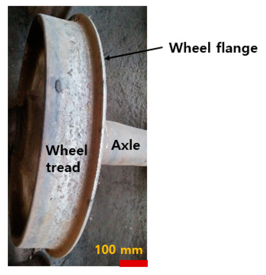
Figure 1.
Wheel with worn flange.
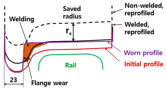
Figure 2.
Overlay welding and reprofiling of worn wheel.
There has been considerable research on wheel flange hard facing in Ukraine, and hard-faced wheels are in service to commercial trains. Gajvoronsky et al. [12] hard-faced a wheel with a composition of 0.625 wt. % C; 0.73 Mn; 0.31 Si; 0.11 V by submerged arc welding. They investigated the influence of post-weld cooling rate on the microstructures and mechanical properties. When the cooling rate changed from 33 °C/s to 11.1 °C/s, martensitic content in the heat-affected zone decreased; the volume fraction of the ferrite-pearlite component increased, the bainite content got stabilized. Markashova et al. [13] studied the effect of welding wire composition on microstructure and mechanical properties. A welding wire with C 0.12 wt. %, Mn 1.0, Si 0.35, Cr 0.67, Ni 0.8, V 0.1, and Mo 0.4 produced a weld metal composed of bainitic and martensitic phases. The weld metal showed a relatively higher yield strength and fracture toughness. Goo et al. [26] developed a new process and welding wire for restoring worn-out railway wheels by submerged arc welding and carried out wear tests using a full-scale disc–disc rolling tester. According to their results, the wear depth of the weld-repaired wheel with bainitic microstructure was much greater than the wear depth of the commercial wheel; but it was less than half of the wear depth of the weld-repaired wheel with ferritic–pearlitic microstructures.
Recently, the study of welding polarity on the mechanical and metallurgical properties of the weld has attracted attention. Aloraier et al. [27] investigated the effect of changing the welding polarity when repairing low carbon steel AISI 1020 with shielded metal arc welding (SMAW). They argued that if the first layer got welded with straight polarity and the second layer with reverse polarity, the second weld with more heat input had the effect of tempering the first layer. Zhang et al. [28] studied the effects of electrode polarity on the droplet transfer mode in self-shielded flux-cored arc welding using a high-speed camera. They welded mild steel (Q235) plates. According to their experimental results, the electrode polarity had a more significant effect on droplet size and generation frequency than arc current and voltage. In the light of arc stability and spatter, reverse polarity welding showed superior characteristics to straight welding. Zhao and Chung [29] simulated droplet transfer behavior in alternating current gas metal arc welding (GMAW). They showed that the droplet size during AC-GMAW welding was larger than that of DC-GMAW welding, and the temperature at the moment of falling off the electrode was lower.
In the present study, the main focus was on welding rods that are useful for hardfacing worn wheels without generating cracks, and the effect of direct current polarity on the mechanical properties, microstructures, fatigue properties, wear properties, and friction of the submerged arc welded wheels. Test specimens were machined using the wheel welded with straight and reverse polarity; and metallurgical and mechanical properties were evaluated by testing.
2. Materials and Methods
2.1. Materials and Welding
After preheating the wheel to 150 °C, the wheel tread surface was welded to a thickness of about 20 mm. Figure 3 shows the welding of a worn wheel. Post-weld heat treatment was performed at 300 °C. Specimens were produced from the welded wheel. The magnitude of current and voltage is closely related to the width and height of the bead, spatter, and welding quality. After several trials, the welding parameters were set. The welding voltage was 30 V; The welding current was 380 A; the rotation speed of the wheel was 365 (mm/min); the wire feeding speed was 7 cm/min. A welding wire of Φ2.0 mm was applied. Since the contact surface of the wheel and rail is under high contact pressure and deformation, it is necessary to develop a welding rod that can secure the wear resistance and toughness of the weld metal. A welding wire containing Cr, Ni, and Mn was developed. Cr forms carbides to improve wear resistance. Mn refines pearlite, improves abrasion resistance, and inhibits the formation of micropores. Ni is an efficient component for improving low-temperature toughness and ductility. The chemical compositions of the wheel and welding wire were analyzed using optical emission spectroscopy (Model: QSN 750-II, OBLF GMBH, Witten, Germany), and the chemical composition of the rail is from the Korean standard (Table 1).
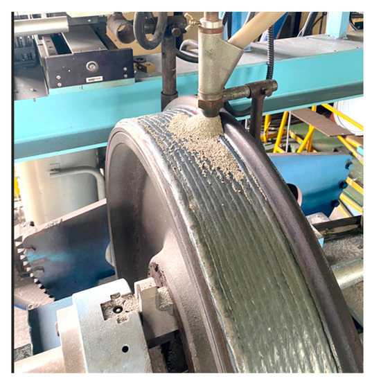
Figure 3.
Submerged arc welding of the worn wheel.

Table 1.
Chemical compositions of the wheel, welding wire and rail.
2.2. Hardness and Microstructures
Specimens were extracted from wheels welded with straight polarity (electrode negative) and reverse polarity (electrode positive). Vickers micro hardness was measured according to KS B 0811 at 0.5 mm intervals using a durometer (Wilson VH3300, Buehler, Lake Bluff, IL, USA). The microstructure was analyzed using a scanning electron microscope (SEM-IT500, JEOL, Tokyo, Japan). Etching of the specimen was carried out according to ASTM E407-07e1.
2.3. Rolling Contact Friction and Wear Test
Similar to hardness specimens, test specimens were taken from the welded wheel as shown in Figure 3. Both discs have the same shape and dimensions (Figure 4a). With a metal saw, the wheel and rail were machined to a bit larger size than the drawing size of the specimen and then processed into a specimen shape with a machine tool and finally, polished. The contact surface roughness measured in the axial direction after fabrication was about 0.64 for the wheel disc and 0.32 in the case of the rail disc on the Ra scale. The difference in the surface roughness of the two specimens was due to different manufacturing processes. Figure 4 shows the disc shape and the sampling locations of the specimens. The three types of wheel specimens were obtained from the positions marked in Figure 4b. The rail disc, the counterpart of the wheel disc, was machined from a commercial rail head as shown Figure 4c. The side faces of the rail disc were parallel to the longitudinal direction of the rail. Figure 5 is a schematic diagram of the disc/disc type rolling contact wear tester. The friction coefficient was obtained from the torque and force that were measured by a torque transducer and a load cell, respectively. The wear test was conducted at a Hertzian contact pressure of 1100 MPa and a slip ratio of 1 %. The contacting discs were cooled by blowing natural air. After 100,000 rotations at an average rotation speed of 500 rpm, the disc weight was measured with a precision scale. The maximum Hertzian contact pressure, is obtained from Equation (1) [30]:
where P is the normal force; B is the disc thickness; E is the elastic constant; R is the equivalent radius of the two discs. R is defined as
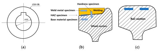
Figure 4.
Rolling contact wear specimen, and sampling locations. (a) Disc; (b) Wheel disc sampling location; (c) Rail disc sampling location.
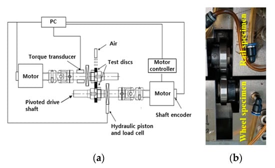
Figure 5.
Rolling contact wear tester. (a) Schematic diagram; (b) Rail disc and wheel disc.
The slip rate was calculated by dividing the difference between the relative speeds of the two rolling discs by the average speed as in Equation (3).
where R is the radius of the disc; w is the angular velocity of the disc. The subscripts r and w denote the rail and the wheel, respectively.
3. Results and Discussion
3.1. Hardness and Microstructures
Figure 6 shows the microhardness distribution of wheels welded with reverse and straight polarity with a load of 9.81 N. The average hardness of the weld metal welded with reverse polarity; 359 HV was slightly higher than in the case of the positive polarity, 356 HV. The maximum hardness in the HAZ was 386 and 396 HV, respectively. This trend was also in the experiments obtained by Aloraier et al. [31] on AISI 1020 mild carbon steel. The hardness of the weld metal welded with reverse polarity was slightly higher than that with straight polarity. In reverse polarity, the electrons go from the specimen to the electrode, and positive ions of the shielding gas flow toward the specimen, which is the anode, and hit the surface of the specimen to clean oxide films on the surface. About 70% of the arc heat goes to the electrode, and 30% of the heat goes to the specimen. In straight polarity, the opposite is the case [31]. The weld bead width welded with straight polarity was wider than that with reverse polarity. The HAZ size with straight polarity was larger. In straight polarity welding, more heat enters the specimen, so the temperature of the fusion zone is higher, and the cooling rate is slower. As a result, the grains grow larger, and the hardness is lower than in the case of reverse polarity. Figure 7 and Figure 8 show microstructures of the specimens welded with reverse polarity and with straight polarity, respectively. The base material and HAZ were composed of ferritic and pearlitic microstructures similar to those of a general low alloy steel wheel [32]. Acicular ferrite with a relatively soft texture existed at the boundary of the pearlitic grains. In the case of straight polarity welding, more ferrite was in the HAZ. Widmanstätten ferrite (ferrite grown from the grain boundaries) was in the HAZ. Comparing the microstructure of the HAZ in Figure 7b or Figure 8a, the grain size of the HAZ welded with straight polarity with more heat input was larger. Weld metal appeared to be composed of martensite, bainite, and pearlite. Similar microstructures were observed in general carbon steel weld metals [33].
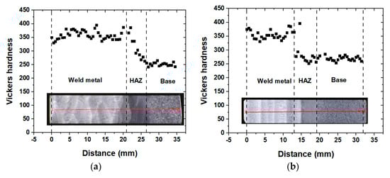
Figure 6.
Microhardness distribution of base material, HAZ, and weld metal. (a) Welded with reverse polarity; (b) Welded with straight polarity.
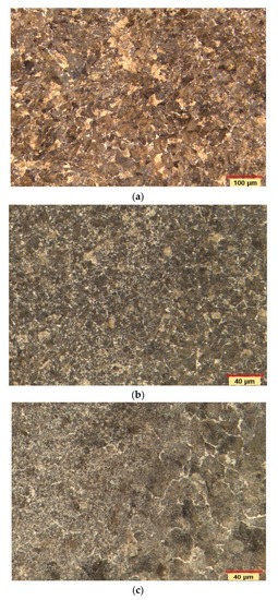
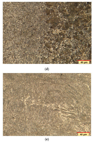
Figure 7.
Microstructures of the specimens welded with reverse polarity. (a) Base material; (b) HAZ; (c) HAZ–Base material interface; (d) Weld metal–HAZ interface; (e) Weld metal.
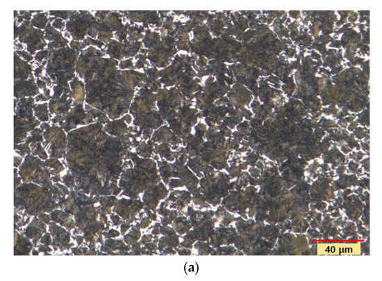
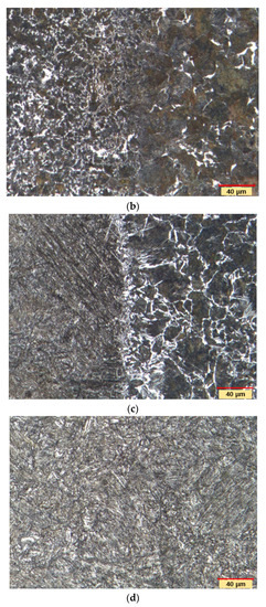
Figure 8.
Microstructures of the specimens welded with straight polarity. (a) HAZ; (b) HAZ–Base interface; (c) Weld metal–HAZ interface; (d) Weld metal.
3.2. Rolling Contact Friction and Wear Test
Figure 9 shows the wear rates and friction coefficients for specimens taken from wheels welded with reverse polarity and straight polarity. The wear rate was defined as the amount of wear divided by the rolling distance and the Hertzian contact area. The friction coefficient decreased in the order of straight polarity welded wheel, reverse polarity welded wheel, HAZ wheel, and base metal wheel. The effect of welding polarity on the coefficient of friction was negligible. The average values of the coefficient of friction for the entire mileage were 0.424, 0.419, 0.378, and 0.371, respectively. The straight polarity welded specimen and the reverse polarity welded specimen had almost constant friction coefficients, whereas the friction coefficients of the HAZ specimen and the base metal specimen gradually decreased with the running distance. One characteristic was that the wear rate of the weld metal disc welded with straight polarity was less than the wear rate of its counterpart, the rail disc. To find out the cause, the microhardness was measured at 0.5 mm intervals along the radius from the contact surface after the wear test. Figure 10a shows the hardness distribution of the weld metal disc, HAZ disc, and its counterpart rail disc welded with reverse polarity. Figure 10b shows the hardness distribution of a weld metal disc welded with straight polarity and its counterpart, a rail disc. The hardness values of the wheel disc and the rail disc depended on the sampling locations of the specimens. The hardness value of the rail disc before the test was 250–300 HV, which was lower than that of the weld metal (350–400 HV). After the wear test, the hardness of the rail disc near the contact surface was higher than that of the weld metal disc. As shown in Figure 10a, the weld metal disc and the rail disc showed almost the same hardness near the surface. The hardness value of the counterpart rail disc of the weld metal disc welded with straight polarity increased up to 500 HV (Figure 10b). Work-hardening of the rail disc by large plastic deformation induced a significant increase in hardness. On the other hand, in the case of the welded metal wheel disc, the hardness increased by 30–40 HV near the surface. The increment is small compared to the increment in the rail disc or HAZ disc. It means that the plastic deformation at which cracks occur is not severe in the case of weld metal discs. It is reported in [13] that plastic deformation of the wheel surface layer increases the strength by 170–230 % and decreases the fracture toughness by 50%.
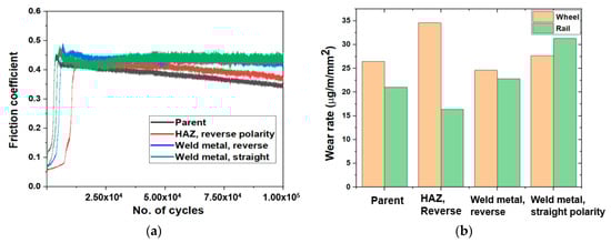
Figure 9.
Results of friction and wear tests. (a) Friction coefficients; (b) Wear rates.
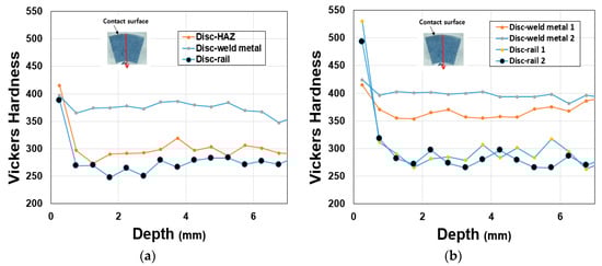
Figure 10.
Hardness distribution along the radial line from the contact surface after the wear test. (a) Discs welded with reverse polarity; (b) Discs welded with straight polarity.
Figure 11 are photographs of the surfaces of the rail and wheel specimens after the wear test. Spalling and cracks were observed in the rail specimen, which had relatively lower hardness compared to the wheel. The surface of the rail specimen in contact with the base wheel had the least damage. No cracks or flaking marks were observed on the surface of the base wheel specimen. It is reported that the main mechanism of this kind of wear is oxidation [34]. The left side of the HAZ specimen was subjected to high heat during welding and the microstructure was changed, so the damage was more severe than the right side, which had the same structure as the base material. The surface of the wheel specimen welded with straight polarity and reverse polarity suffered severe spalling, adhesive wear and delamination. The degree of damage of the two specimens was similar.
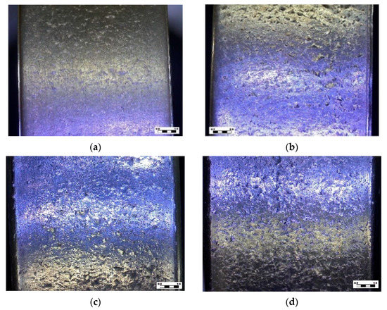
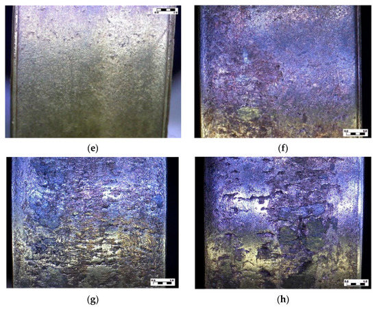
Figure 11.
Contact surfaces of the discs after wear test. (a) Rail against parent wheel; (b) Rail against HAZ wheel; (c) Rail against reverse polarity weld wheel; (d) Rail against straight polarity weld wheel; (e) Parent wheel; (f) HAZ wheel; (g) Reverse polarity weld wheel; (h) Straight polarity weld wheel.
Figure 12 shows optical micrographs of the contact area of the specimens welded with reverse polarity observed from the side. Overall, the test specimens underwent severe shear deformation and cracks grew from the surface, tilted slightly with the surface, and propagated inward to form fractured fragments. Such deformation behavior and wear patterns appeared in the literature [34]. Figure 12a shows the deformation behavior of the base wheel specimen. The white part was pearlite, and the brown part was ferrite. The microstructure near the surface was subjected to severe shear deformation in the left direction due to repeated shear stress, and cracks occurred on the surface and propagated parallel to the surface to a depth of about 7 μm. The crack propagated along the direction opposite to the slip force acting on the contact surface. The deformation behavior similar to that of the parent wheel specimen occurred in the HAZ wheel specimen (Figure 12b); and cracks were observed along the plastic slip band boundary under the surface. In the weld metal wheel specimen shown in Figure 12c, the cracks generated on the surface developed at a larger angle from the surface and produced larger wear particles. This fact was consistent with the phenomenon in Figure 11 that the wear surface of the weld metal specimen was rougher than that of the parent and HAZ specimens. The deformation behavior of the rail specimen was also similar to that of the wheel specimen. Figure 12d shows the deformation behavior of the rail specimen, which was the counterpart of the parent wheel specimen. The surface layer underwent severe shear deformation, and cracks occurred on the surface and progressed along the shear deformation boundary. In the HAZ rail specimen, the inclination angle of the crack propagation was greater (Figure 12e). Several surface cracks were in the test specimen of the counter material of the weld metal wheel (Figure 12f), and the wear surface was rough due to the larger delaminated particles. In addition, several microcracks existed in the subsurface, so the amount of wear was expected to be great. This result was consistent with Figure 9 showing the amount of wear. Figure 13 shows optical micrographs of the contact area of the specimens welded with straight polarity observed from the side. The plastic deformation of the subsurface layer of the rail disc was very severe, and the cracks generated at a depth of 60 μm developed almost parallel to the contact surface. The plastic deformation of the subsurface layer of the rail disc was very severe, and the cracks generated at a depth of 60 μm developed almost parallel to the contact surface. It is inferred that the delamination due to crack propagation that occurred deep under the contact surface could be the cause why the wear rate of the rail disc was greater than that of the weld metal, which was the counterpart material.
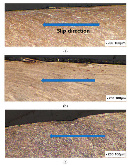
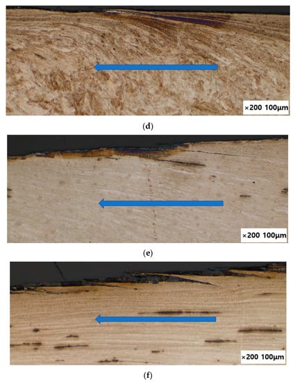
Figure 12.
Optical micrographs of the contact area of the worn specimens welded with reverse polarity. (a) Parent wheel specimen; (b) HAZ wheel specimen; (c) Weld metal wheel specimen; (d) Rail specimen against parent wheel specimen; (e) Rail specimen against HAZ wheel specimen; (f) Rail specimen against weld metal wheel specimen.
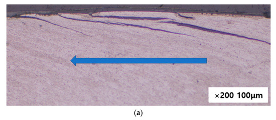
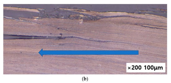
Figure 13.
Optical micrographs of the contact area of the worn specimens welded with straight polarity. (a) Weld metal disc; (b) Rail disc.
4. Conclusions
The hardfacing of worn railroad car wheels by sub-merged arc welding is a subject of great interest. In this study, the effects of straight and reverse polarity welding on the hardness, microstructure, friction, and wear characteristics of the welded wheel were experimentally studied. There were no welding defects or cracks when the wheels were hard-faced with the welding wire and welding procedure presented in this research. The hardness of the weld metal welded with reverse polarity was 3 HV greater than that of welded with straight polarity. The difference was negligible. More ferrite was observed in the HAZ in the case of straight polarity welding. In the twin disc wear test using a commercial rail as a counterpart, the friction coefficients of straight polarity weld metal and reverse polarity weld metal were similar. The wear rates of the wheel disc welded with reverse polarity and its counterpart rail disc were 11% and 27% lower than those welded with straight polarity, respectively. The hardness of the rail before the wear test was in the range of 250–300 HV. After the wear test, it soared to 500 HV. In the case of the weld metal disc, the surface hardness did not change significantly. In the wear test of the base wheel and rail specimens, delamination wear due to subsurface crack propagation and oxidation wear were mixed. In the case of HAZ and weld metal, delamination by surface crack propagation was considered the principal wear mechanism. Since the wheel of a railroad car must satisfy the fracture toughness and Charpy impact absorption energy standards, further research on these needs to be carried out in the future.
Author Contributions
Conceptualization, Y.-J.L.; methodology, B.-C.G., J.-W.S.; welding, Y.-J.L.; wear test, J.-W.S.; fatigue test, B.-C.G.; resources, Y.-J.L.; data curation, J.-W.S.; writing—original draft preparation, B.-C.G.; writing—review and editing, B.-C.G.; supervision, Y.-J.L.; project administration, Y.-J.L.; funding acquisition, Y.-J.L. All authors have read and agreed to the published version of the manuscript.
Funding
This research was funded by Korean Ministry of Trade, Industry and Energy (Project No. 20217710100010).
Institutional Review Board Statement
Not applicable.
Informed Consent Statement
Not applicable.
Data Availability Statement
Not applicable.
Conflicts of Interest
The author declares no conflict of interest.
References
- Bayhan, Y. Reduction of wear via hardfacing of chisel ploughshare. Tribol. Int. 2006, 39, 570–574. [Google Scholar] [CrossRef]
- Selvi, S.; Sankaran, S.; Srivatsavan, P.R. Comparative study of hardfacing of valve seat ring using MMAW process. J. Mater. Processing Technol. 2008, 207, 356–362. [Google Scholar] [CrossRef]
- Eremin, E.N.; Losev, A.S. Wear resistance increase of pipeline valves by overlaying welding flux-cored wire. Procedia Eng. 2015, 113, 435–440. [Google Scholar] [CrossRef][Green Version]
- Fernandez, J.E.; Vijande, R.; Tucho, R.; Rodriguez, J.; Martin, A. Materials selection to excavator teeth in mining industry. Wear 2001, 250, 11–18. [Google Scholar] [CrossRef]
- Singla, S.; Kang, A.S.; Grewal, J.S.; Cheema, G.S. Wear behavior of weld overlay on excavator bucket teeth. Procedia Mater. Sci. 2014, 5, 256–266. [Google Scholar] [CrossRef]
- Gorunov, A.I. Complex refurbishment of titanium turbine blades by applying heat-resistant coatings by direct metal deposition. Eng. Fail. Anal. 2018, 86, 115–130. [Google Scholar] [CrossRef]
- Pauzi, A.A.; Ghazali, M.J.; Zamri, W.F.H.W.; Rajabi, A. Wear characteristics of superalloy and hardface coatings in gas turbine applications—A Review. Metals 2020, 10, 1171. [Google Scholar] [CrossRef]
- Yang, K.; Zhang, Z.X.; Hu, W.Q.; Bao, Y.F.; Jiang, Y.F. A new type of submerged-arc flux-cored wire used for hardfacing continuous casting rolls. J. Iron Steel Res. Int. 2011, 18, 74–79. [Google Scholar] [CrossRef]
- Srikarun, B.; Oo, H.Z.; Prapa, M. Influence of different welding processes on microstructure, hardness, and wear behavior of martensitic hardfaced cladding. J. Mater. Eng. Perform. 2021, 30, 8984–8995. [Google Scholar] [CrossRef]
- Malinov, V.L.; Malonov, L.S.; Golyakevich, A.A.; Orlov, L.N. Improving the endurance of crane wheels using new flux-cored wire Veltek-N285C. J. Weld. Int. 2016, 30, 880–883. [Google Scholar] [CrossRef]
- Anan’ev, S.P.; Korotkov, V.A.; Goloviznin, B.L.; Kozlov, V.V. Improving the technology for hardfacing crane wheels. J. Weld. Int. 2007, 21, 534–537. [Google Scholar] [CrossRef]
- Gajvoronsky, A.A.; Poznyakov, V.D.; Sarzhevsky, V.A.; Vasiliev, V.G.; Orlovsky, V.Y. Influence of thermo-deformational cycle of hardfacing on the structure and properties of railway wheels at their reconditioning. Paton Weld. J. 2010, 5, 15–18. [Google Scholar]
- Markisha, L.I.; Poznyakov, V.D.; Gajvoronsky, A.A.; Berdinkova, E.N.; Alekseenko, T.A. Structure and properties of railway wheel surface after restoration surfacing and service loading. Paton Weld. J. 2015, 5–6, 96–100. [Google Scholar] [CrossRef][Green Version]
- Cui, W.; Karnati, S.; Zhang, X.; Burns, E.; Liou, F. Fabrication of AlCoCrFeNi high entropy alloy coating on an AISI 304 substrate via a CoFe2Ni intermediate layer. Entropy 2019, 21, 2. [Google Scholar] [CrossRef]
- Ni, C.; Shi, Y.; Liu, J.; Huang, G. Characterization of Al0.5FeCu0.7NiCoCr high entropy alloy coating on aluminum alloy by laser cladding. Opt. Laser Technol. 2018, 105, 257–263. [Google Scholar] [CrossRef]
- Qiu, X.W. Corrosion behavior of Al2CrFeCo CuNiTi high-entropy alloy coating in alkaline solution and salt solution. Results Phys. 2019, 12, 1737–1741. [Google Scholar] [CrossRef]
- Jiang, Y.Q.; Li, J.; Juan, Y.F.; Lu, Z.J.; Jia, W.L. Evolution in microstructure and corrosion behavior of AlCoCrxFeNi high-entropy alloy coatings fabricated by laser cladding. J. Alloys Compd. 2019, 775, 1–14. [Google Scholar] [CrossRef]
- Qiu, X.W. Microstructure, hardness and corrosion resistance of Al2CoCrCuFeNiTix high-entropy alloy coatings prepared by rapid solidification. J. Alloys Compd. 2018, 735, 359–364. [Google Scholar] [CrossRef]
- Cai, Z.; Cui, X.; Liu, Z.; Li, Y.; Dong, M.; Jin, G. Microstructure and wear resistance of laser cladded Ni-Cr-Co-Ti-V high-entropy alloy coating after laser remelting processing. Opt. Laser Technol. 2018, 99, 276–281. [Google Scholar] [CrossRef]
- Juan, Y.F.; Li, J.; Jiang, Y.Q.; Jia, W.L.; Lu, Z.J. Modified criterions for phase prediction in the multi-component laser-clad coatings and investigations into microstructural evolution/wear resistance of FeCrCoNiAlMox laser-clad coatings. Appl. Surf. Sci. 2019, 465, 700–714. [Google Scholar] [CrossRef]
- Mendez, P.F.; Barnes, N.; Bell, K.; Borlea, S.D.; Gajapathi, S.S.; Guest, S.D.; Izadi, H.A.; Gol, K.; Wood, G. Welding processes for wear resistant overlays. J. Manuf. Process 2014, 16, 4–25. [Google Scholar] [CrossRef]
- Zahiri, R.; Sundaramoorthy, R.; Lysz, P.; Subramanian, C. Hardfacing using ferro-alloy powder mixtures by submerged arc welding. Surf. Coat. Technol. 2014, 260, 220–229. [Google Scholar] [CrossRef]
- Öteyaka, M.Ö.; Arslan, A.E. Wear and corrosion characterisation of AISI 1030, AISI 1040 and AISI 1050 steel coated with Shielded Metal Arc Welding (SMAW) and Plasma Transfer Arc (PTA) methods. Sådhanå 2021, 46, 134. [Google Scholar] [CrossRef]
- Günther, K.; Bergmann, J.P.; Suchodoll, D. Hot wire-assisted gas metal arc welding of hypereutectic FeCrC hardfacing alloys: Microstructure and wear properties. Surf. Coat. Technol. 2018, 334, 420–428. [Google Scholar] [CrossRef]
- Gianni, A.; Ghidini, A.; Karlsson, T.; Ekberg, A. Bainitic steel grade for solid wheels: Metallurgical, mechanical, and in-service testing. Proc. IMechE Part F J. Rail Rapid Transit 2009, 223, 163–171. [Google Scholar] [CrossRef]
- Goo, B.C.; Lee, Y.J. Railway vehicle wheel restoration by submerged arc welding and its characterization. Science 2020, 2, 33. [Google Scholar] [CrossRef]
- Aloraier, A.; Albannai, A.; Alaskari, A.; Alawadhi, M. TBW technique by varying weld polarities in SMAW as an alternative to PWHT. Int. J. Press. Vessel. Pip. 2021, 194, 104505. [Google Scholar] [CrossRef]
- Zhang, H.; Shi, Y.; Gu, Y.; Xie, J.; Li, C. Effects of electrode polarity on the droplet transfer mode in self-shielded flux-cored arc welding. J. Manuf. Processes 2020, 58, 478–488. [Google Scholar] [CrossRef]
- Zhao, Y.; Chung, H. Numerical simulation of droplet transfer behavior in variable polarity gas metal arc welding. Int. J. Heat Mass Transf. 2017, 111, 1129–1141. [Google Scholar] [CrossRef]
- Timoshenko, S.P.; Goodier, J.N. Theory of Elasticity, 3rd ed.; McGraw Hill: New York, NY, USA, 1970; pp. 403–420. [Google Scholar]
- Aloraier, A.; Al-Fadhalah, K.; Paradowska, A.M.; Alfaraj, E. Effect of welding polarity on bead geometry, microstructure, microhardness, and residual stresses of 1020 steel. J. Eng. Res. 2014, 2, 137–160. [Google Scholar] [CrossRef]
- Faccoli, M.; Ghidini, A.; Mazzù, A. Changes in the Microstructure and Mechanical Properties of Railway Wheel Steels as a Result of the Thermal Load Caused by Shoe Braking. Metall. Mater. Trans. A 2019, 50, 1701–1714. [Google Scholar] [CrossRef]
- Jorge, J.C.F.; de Souza, L.F.G.; Mende, M.C.; Bott, I.S.; Araújo, L.S.; dos Santos, V.R.; Rebello, J.M.A.; Evans, G.M. Microstructure characterization and its relationship with impact toughness of C–Mn and high strength low alloy steel weld metals—A review. J. Mater. Res. Technol. 2021, 10, 471–501. [Google Scholar] [CrossRef]
- Zhou, Y.; Peng, J.F.; Wang, W.J.; Jin, X.S.; Zhu, M.H. Slippage effect on rolling contact wear and damage behavior of pearlitic steels. Wear 2016, 362–363, 78–86. [Google Scholar] [CrossRef]
Publisher’s Note: MDPI stays neutral with regard to jurisdictional claims in published maps and institutional affiliations. |
© 2022 by the authors. Licensee MDPI, Basel, Switzerland. This article is an open access article distributed under the terms and conditions of the Creative Commons Attribution (CC BY) license (https://creativecommons.org/licenses/by/4.0/).