
Prediction of a Material Property Gradient near the Friction Surface in Axisymmetric Extrusion and Drawing

Abstract
:1. Introduction
2. Statement of the Problem
3. General Solution
4. Strain Rate and Work Rate Intensity Factors
5. Thickness of the Layer of Intensive Plastic Deformation and Hardness at the Friction Surface
6. Numerical Examples
7. Discussion
Funding
Institutional Review Board Statement
Informed Consent Statement
Data Availability Statement
Conflicts of Interest
Nomenclature
| n | constitutive parameter involved in Hosford’s yield criterion |
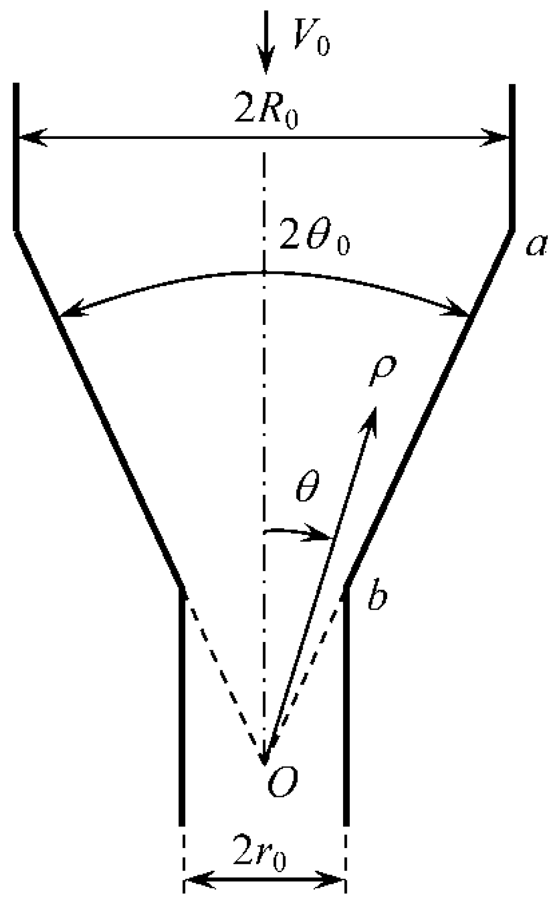
| final radius of the rod | |
| stress variables introduced in Equation (10) | |
| radial velocity | |
| plastic work rate | |
| hardness at the friction surface | |
| initial radius of the rod | |
| work rate intensity factor | |
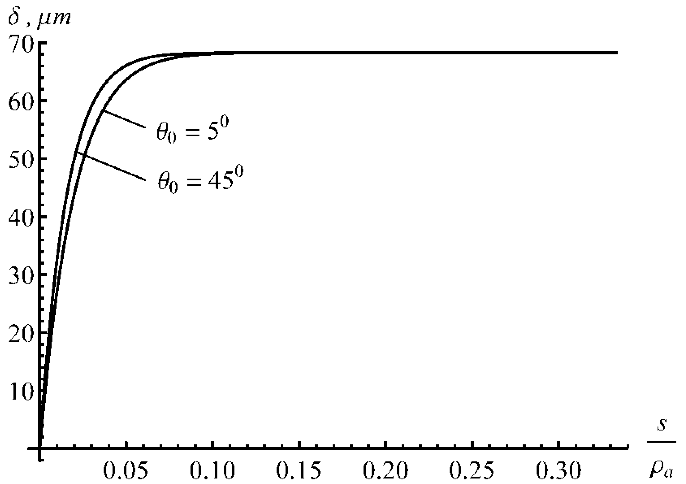
| thickness of the layer of intensive plastic deformation | |
| die semi-angle | |
| strain rate components referred to the spherical coordinate system | |
| principal strain rates | |
| spherical coordinate system | |
| stress components referred to the spherical coordinate system | |
| tensile yield stress | |
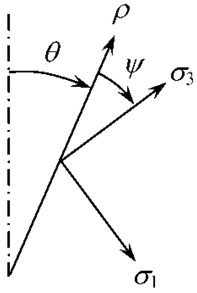
| principal stresses | |
| shear yield stress | |
| angle between the axis and the direction of the principal stress σ3 | |
| integrated work rate intensity factor |
References
- Griffiths, B.J. Mechanisms of white layer generation with reference to machining and deformation processes. ASME J. Tribol. 1987, 109, 525–530. [Google Scholar] [CrossRef]
- Griffiths, B.J.; Furze, D.C. Tribological advantages of white layers produced by machining. ASME J. Tribol. 1987, 109, 338–342. [Google Scholar] [CrossRef]
- Choi, Y. Influence of a white layer on the performance of hard machined surfaces in rolling contact. Proc. Inst. Mech. Eng. B J. Eng. Manuf. 2010, 224, 1207–1215. [Google Scholar] [CrossRef]
- Murai, T.; Matsuoka, S.; Miyamoto, S.; Oki, Y. Effects of extrusion conditions on microstructure and mechanical properties of AZ31B magnesium alloy extrusions. J. Mater. Process. Technol. 2003, 141, 207–212. [Google Scholar] [CrossRef]
- Kajino, S.; Asakawa, M. Effect of “additional shear strain layer” on tensile strength and microstructure of fine drawn wire. J. Mater. Process. Technol. 2006, 177, 704–708. [Google Scholar] [CrossRef]
- Uematsu, Y.; Tokaji, K.; Kamakura, M.; Uchida, K.; Shibata, H.; Bekku, N. Effect of extrusion conditions on grain refinement and fatigue behaviour in magnesium alloys. J. Mater. Sci. Eng. A 2006, 434, 131–140. [Google Scholar] [CrossRef]
- Tang, W.; Huang, S.; Zhang, S.; Li, D.; Peng, Y. Influence of extrusion parameters on grain size and texture distributions of AZ31 alloy. J. Mater. Process. Technol. 2011, 211, 1203–1209. [Google Scholar] [CrossRef]
- Sanabria, V.; Mueller, S.; Reimers, W. Microstructure evolution of friction boundary layer during extrusion of AA 6060. Procedia Eng. 2014, 81, 586–591. [Google Scholar] [CrossRef] [Green Version]
- Alexandrov, S.; Jeng, Y.-R.; Hwang, Y.-M. Generation of a fine grain layer in the vicinity of frictional interfaces in direct extrusion of AZ31 alloy. ASME J. Manuf. Sci. Eng. 2015, 137, 051003. [Google Scholar] [CrossRef]
- Hwang, Y.-M.; Huang, T.-H.; Alexandrov, S. Manufacture of gradient microstructures of magnesium alloys using two—Stage extrusion dies. Steel Res. Int. 2015, 86, 956–961. [Google Scholar] [CrossRef]
- Stolyarov, A.; Polyakova, M.; Atangulova, G.; Alexandrov, S.; Lang, L. Effect of frictional conditions on the generation of fine grain layers in drawing of thin steel wires. Metals 2019, 9, 819. [Google Scholar] [CrossRef] [Green Version]
- Stolyarov, A.; Polyakova, M.; Atangulova, G.; Alexandrov, S. Effect of die angle and frictional conditions on fine grain layer generation in multi-pass drawing of high carbon steel wire. Metals 2020, 10, 1462. [Google Scholar] [CrossRef]
- Alexandrov, S.; Jeng, Y.-R.; Kuo, C.-Y.; Chen, C.-Y. Towards the theoretical/experimental description of the evolution of material properties near frictional interfaces in metal forming processes. Trib. Int. 2022, 171, 107518. [Google Scholar] [CrossRef]
- Alexandrov, S.; Richmond, O. Singular plastic flow fields near surfaces of maximum friction stress. Int. J. Non-Linear Mech. 2001, 36, 1–11. [Google Scholar] [CrossRef]
- Facchinetti, M.; Miszuris, W. Analysis of the maximum friction condition for green body forming in an ANSYS environment. J Eur. Ceram. Soc. 2016, 36, 2295–2302. [Google Scholar] [CrossRef] [Green Version]
- Alexandrov, S.; Kuo, C.-Y.; Jeng, Y.-R. A numerical method for determining the strain rate intensity factor under plane strain conditions. Cont. Mech. Therm. 2016, 28, 977–992. [Google Scholar] [CrossRef]
- Durban, D. Radial flow simulation of drawing and extrusion of rigid/hardening materials. Int. J. Mech. Sci. 1983, 25, 27–39. [Google Scholar] [CrossRef]
- Hosford, W.F. A generalized isotropic yield criterion. Trans. ASME J. Appl. Mech. 1972, 39, 607–609. [Google Scholar] [CrossRef]
- Shield, R.T. Plastic flow in a converging conical channel. J. Mech. Phys. Solids. 1955, 3, 246–258. [Google Scholar] [CrossRef]
- Alexandrov, S.; Barlat, F. Modeling axisymmetric flow through a converging channel with arbitrary yield condition. Acta Mech. 1999, 133, 57–68. [Google Scholar] [CrossRef]
- Alexandrov, S.; Mustafa, Y. The strain rate intensity factor in the plane strain compression of thin anisotropic metal strip. Meccanica 2014, 49, 2901–2906. [Google Scholar] [CrossRef]
- Taylor, G.I. Plastic strains in metals. J. Inst. Metals 1938, 62, 307–324. [Google Scholar]
- Alexandrov, S.E.; Goldstein, R.V. The similarity of grain-size evolution near frictional interfaces and in the process of equal-channel angular pressing. Dokl. Phys. 2013, 58, 177–180. [Google Scholar] [CrossRef]
- Wetscher, F.; Vorhauer, A.; Stock, R.; Pippan, R. Structural refinement of low alloyed steels during severe plastic deformation. Mater. Sci. Eng. 2004, 387–389, 809–816. [Google Scholar] [CrossRef]
- Pippan, R.; Wetscher, F.; Hafok, M.; Vorhauer, A.; Sabirov, I. The limits of refinement by severe plastic deformation. Adv. Eng. Mater. 2006, 8, 1046–1056. [Google Scholar] [CrossRef]
- Xun, Y.; Mohamed, F.A. Refining efficiency and capability of top-down synthesis of nanocrystalline materials. Mater. Sci. Eng. 2011, 528, 5446–5452. [Google Scholar] [CrossRef]
- Mohamed, F.A.; Dheda, S.S. On the minimum grain size obtainable by equal channel angular pressing. Mater. Sci. Eng. 2013, 580, 227–230. [Google Scholar] [CrossRef]
- Zhou, W.; Yu, J.; Lin, J.; Dean, T.A. Effects of die land length and geometry on curvature and effective strain of profiles produced by a novel sideways extrusion process. J. Mater. Process. Technol. 2020, 282, 116682. [Google Scholar] [CrossRef]
- Zhou, W.; Yu, J.; Lu, X.; Lin, J.; Dean, T.A. A comparative study on deformation mechanisms, microstructures and mechanical properties of wide thin-ribbed sections formed by sideways and forward extrusion. Int. J. Mach. Tools Manuf. 2021, 168, 103771. [Google Scholar] [CrossRef]


Publisher’s Note: MDPI stays neutral with regard to jurisdictional claims in published maps and institutional affiliations. |
© 2022 by the author. Licensee MDPI, Basel, Switzerland. This article is an open access article distributed under the terms and conditions of the Creative Commons Attribution (CC BY) license (https://creativecommons.org/licenses/by/4.0/).
Share and Cite
Lyamina, E. Prediction of a Material Property Gradient near the Friction Surface in Axisymmetric Extrusion and Drawing. Metals 2022, 12, 1310. https://doi.org/10.3390/met12081310
Lyamina E. Prediction of a Material Property Gradient near the Friction Surface in Axisymmetric Extrusion and Drawing. Metals. 2022; 12(8):1310. https://doi.org/10.3390/met12081310
Chicago/Turabian StyleLyamina, Elena. 2022. "Prediction of a Material Property Gradient near the Friction Surface in Axisymmetric Extrusion and Drawing" Metals 12, no. 8: 1310. https://doi.org/10.3390/met12081310
APA StyleLyamina, E. (2022). Prediction of a Material Property Gradient near the Friction Surface in Axisymmetric Extrusion and Drawing. Metals, 12(8), 1310. https://doi.org/10.3390/met12081310