Article

Development and Application of Asynchronous Roll Shifting Strategy of Double Attenuation Work Roll in Hot Rolling

1
School of Metallurgy and Energy, North China University of Science and Technology, Tangshan 063210, China
2
Tangshan Donghua Steel Enterprise Group Co., Ltd., Tangshan 063210, China
3
National Engineering Research Center for Advanced Rolling Technology, University of Science and Technology Beijing, Beijing 100083, China
*
Author to whom correspondence should be addressed.
Metals 2022, 12(8), 1265; https://doi.org/10.3390/met12081265
Submission received: 19 June 2022 / Revised: 13 July 2022 / Accepted: 15 July 2022 / Published: 28 July 2022
(This article belongs to the Special Issue Plastic Deformation and Metal Plasticity)

Abstract

:
In view of the problems of the violent crown fluctuation and unstable shape control in the endless rolling production line, the field measurement results show that the abnormal crown fluctuation is related to the shifting limit position of the work roll after the uneven wear occurs. For this reason, the asynchronous roll shifting strategy is developed, which has double attenuation of roll shifting amplitude and roll shifting step. By coupling the roll wear contour model, the roll thermal contour model and the rolls-strip integrated model, the strip crown calculation model of the whole rolling unit is established, and the causes of abnormal crown fluctuation are revealed theoretically. In addition, the simulation analysis of the important parameters of asynchronous roll shifting strategy of double attenuation working roll is made by using this model. The number of strips in a roll shifting cycle is found to be too large or too small, which is not benefited by the control of the strip crown stability due to the influence of roll wear and roll thermal crown. A rolling unit has many shifting cycles. When the roll shifting amplitude at the end of a rolling unit is smaller, which can make the amplitude difference between adjacent roll shifting cycles greater, it is easier to avoid the uneven edge wear area and to control the strip crown stability. The industrial test shows that the maximum crown fluctuation in a rolling unit decreases by 21.05%, and the maximum crown fluctuation of adjacent strips decreases by 28.57%, which significantly improves the stability of crown control.

1. Introduction

Under the international background of carbon peaking and carbon neutralization, the endless rolling, as the third generation of continuous casting and rolling technology [1], has the advantages of energy saving and emission reduction, high-dimensional accuracy of products, stability of microstructure and properties, and being suitable for batch rolling of ultra-thin (thickness less than 1.2 mm) products, which has been a cause of concern by many iron and steel enterprises [2]. In 2009, Arvedi obtained the world’s first ESP (endless strip processing) production line and initiated industrial production [3]. In the same year, POSCO of Korea cooperated with Danieli company to put into production CEM (compact endless casting and rolling mill) hot rolling production line, with the peak casting drawing speeds up to 8 m/s, which can stably produce thin, low-carbon steel and high-strength steel [4,5]. In 2015, Rizhao Iron and Steel Company of China cooperated with Arvedi company to introduce the first ESP production line in China, and five ESP production lines were successively put into operation in the next five years [6,7]. In 2019, Shougang cooperated with Danieli and put into operation the world’s first multimode continuous casting and rolling production line [8,9], which can generate three production modes of single billet, semi-endless, and totally endless. The research object of this study is the endless rolling line developed by Tangshan Donghua company, also known as DSCCR (Donghua Steel Continuous Casting Rolling), which was put into operation in June 2019. The main products include SPHC and Q235B. The layout of the production line is shown in Figure 1. The main equipment includes single strand high-casting speed slab caster (CCM), 1#pendulum shear (PS1), double regenerative roller hearth furnace (TF1), two roughing mills (RM), 2#pendulum shear (PS1), double regenerative roller hearth furnace (TF2), six finishing mills (FM), high-speed flying shear (HSS), and two coilers (DC). In addition to total hot rolling, the production line also has the characteristics of single block and semi-hot flexible rolling processes. In this production line, due to the existence of an intermediate heating device, the temperature control accuracy is high, and the influence of temperature fluctuation is small; therefore, products with high convexity stability can be produced. However, in actual production, there is a problem of crown periodic fluctuation related to roll shifting period. Therefore, this paper proposes a dual attenuation asynchronous roll shifting strategy, which can help to avoid the downstream stands that reach the roll shifting zero position, and at the same time, avoid the area with large edge wear. Through the established numerical simulation model, the effect of roll shifting strategy is simulated, and the rolling test is performed on the production line. The double attenuation asynchronous roll shifting strategy is found to effectively improve the crown stability of the unit.

2. The Field Problem of Strip Crown Fluctuation

Strip shape is one of the most important quality indexes for hot-rolled steel strip. In the aspect of strip shape control of the DSCCR line, CVC (continuously variable crown) roll contour is used to control the crown of the three upstream stands, and the roll shifting position is set according to the crown control requirements. The secondary parabolic concave roll contour is used to ensure the rolling stability of the three downstream stands, and the fixed amplitude roll shifting strategy is used for periodic roll shifting. Compared with the conventional hot strip production line due to the same strip width, longer rolling length, and more thin specifications in rolling unit, the crown fluctuates violently in the middle and later stages of the rolling unit, which leads to the instability of the shape of self-learning results; these shape problems and even abnormal production shutdown accidents often occur, which poses a severe challenge to the high-efficiency and stable production of the production line. Figure 2 shows the measured crown results in a rolling unit and the roll shift positions of stands F4, F5, and F6 (F is the abbreviation of finish mill). The figure shows that serious crown fluctuation will occur in the middle and later stages of the rolling unit, which will bring instability to the production. The operator must cancel the automatic roll shifting and change to manual adjustment, so that only a single stand can perform manual roll shifting on one side, which greatly increases the difficulty of control.
In the complex hot rolling conditions, roll wear is inevitable, but how to ensure uniform wear of roll has been researched by many scholars. In order to give consideration to roll wear control and rolling stability control, Shao et al. [10] proposed a roll shifting strategy with variable stroke. To realize the asynchronous roll shifting of three stands, He et al. [11] proposed the sinusoidal asynchronous roll shifting strategy. However, due to the characteristics of sine function, the step length at the limit position is small; especially in the case of equal width rolling, it will increase the uneven wear at the limit position of roll shifting. In addition, Yao et al. [12] also proposed a special roll shifting strategy for ATR (asymmetry taper roll) contour to control the edge drop during silicon steel rolling.
To improve the stability of strip crown control in hot rolling line, it is necessary to fully consider the characteristics of the hot rolling line, develop the amplitude attenuation and step attenuation of downstream stands, and ensure the asynchronous roll shifting strategy between stands, ensuring uniform wear of work rolls and effectively avoiding the adverse impact of severe wear between stands on strip crown control. In order to comprehensively analyze the control effect of the parameters in the double attenuation asynchronous roll shifting strategy on the strip crown stability of the whole rolling unit and to determine the appropriate roll shifting strategy parameters, it is necessary to establish a calculation model that can predict the strip crown of the whole rolling unit according to the rolling process parameters.

3. The Crown Calculation Model of Multi-Stand Continuous Rolling

The influence factors of strip crown include roll wear, roll deflection, roll thermal expansion, and so on. In order to ensure the reliability of the research process, a simulation model for calculating the strip crown of the whole rolling unit is established by coupling the roll wear model, roll thermal expansion model, and rolls-strip integrated model. The integrated rolls-strip model provides the parameters of contact pressure and contact arc length for the roll wear model, while the roll wear model and the roll thermal expansion model provide the comprehensive roll contour parameters for the integrated rolls-strip model. Through the data transfer between the models, the mutual coupling is realized, and the six-stand continuous rolling of the DSCCR production line is simulated. Then, the strip crown in a rolling unit under the condition of multifactor coupling is obtained.

3.1. Roll Wear Model

Considering the wear mechanism of hot rolling roll and the main factors affecting wear, the wear amount of work roll after rolling a coil of strip steel is calculated by the following formula [13]:
w ( x ) = k 0 L z p k 1 l s D w f ( x )
where x is the axial coordinate of work roll, m; w(x) is the radius wear at x position, μm; LZ is the rolling length, km; p is the rolling pressure per unit area, Pa; ls is the contact arc length, m; Dw is the diameter of work roll, m; k0 is the model parameter, which is related to strip material, work roll material and strip temperature; k1 is the influence index of rolling pressure per unit area; and f(x) is a function to describe the degree of axial uneven wear of roller.
The wear distribution is characterized by the gradual increase in wear from the middle to the edge of the strip. On the one hand, it is determined by the distribution of rolling force; on the other hand, it is caused by other factors, such as high-deformation resistance due to temperature drop at the edge of the strip and tensile stress and shear stress at the edge flattening transition part, which makes the wear easier to occur [14]. In a small range from the edge of the strip, the wear has a downward trend, so that an extreme high point is formed at the edge. On the one hand, the rolling force is reduced due to the existence of lateral flow at the edge. On the other hand, it is more important to consider that the strip has a certain probability of left–right deviation; therefore, a part of the wear at the edge will be transferred outside the width of the strip and a slopelike wear distribution is formed [15]. In addition, the parts not in contact with the strip also have microwear, which is caused by the contact friction between the work roll and the backup roll. Its value is relatively small, so it is ignored.

3.2. Roll Thermal Contour Model

The coolant sprayed by the roll cooling system directly acts on the work roll. The purpose of controlling the loaded roll gap is achieved by changing the thermal contour. Because it is impossible to measure the thermal contour directly in the rolling process, a temperature field model is established to predict the change of the thermal contour. In the rolling process, only a large temperature gradient exists in the surface layer of the work roll near the roll gap, so the heat conduction in the circumferential direction of the work roll can be ignored. The differential equation of heat conduction is as follows:
ρ c p T t = λ ( 2 T x 2 + 1 r T r + 2 T r 2 )
where T, ρ, cp, and λ are the temperature, K, density, kg·m3, specific heat capacity, W/(m·K), and coefficient of thermal expansion, 10−6/K; r is the radial coordinate of the work roll, m; and x is the axial coordinate of the work roll, m.
There are many studies on the solution of Equation (2). The two-dimensional alternating difference method can meet the needs of industrial application in terms of calculation speed and accuracy and has been widely used in actual production [16,17].
In the process of modeling, more attention should be focused on the meshing of the roll temperature field. As shown in Figure 3, the work roll is divided into many rings with the horizontal axis as the common axis in the three-dimensional space. The closer the work roll is to the surface, the more intense the temperature change; therefore, the mesh near the surface is dense, the radial step size decreases by 10% near the strip direction, and the mesh inside the work roll and at the roll neck is sparse, reducing the number of nodes and making the calculation time short.
The nonuniform temperature field inside the work roll results in the nonuniform thermal expansion. Based on the elastic theory, assuming that the roll is an infinite cylinder, and its temperature is symmetrically distributed with respect to the roll axis, the thermal expansion at different positions along the axial direction is:
u x , t = 4 ( 1 + ν ) β R 0 R ( T x , r , t T 0 ) r d r
where ν is Poisson’s ratio; β is the linear thermal expansion coefficient of work roll, 1/°C; R is the radius of work roll, mm; and T0 is the initial temperature, °C.

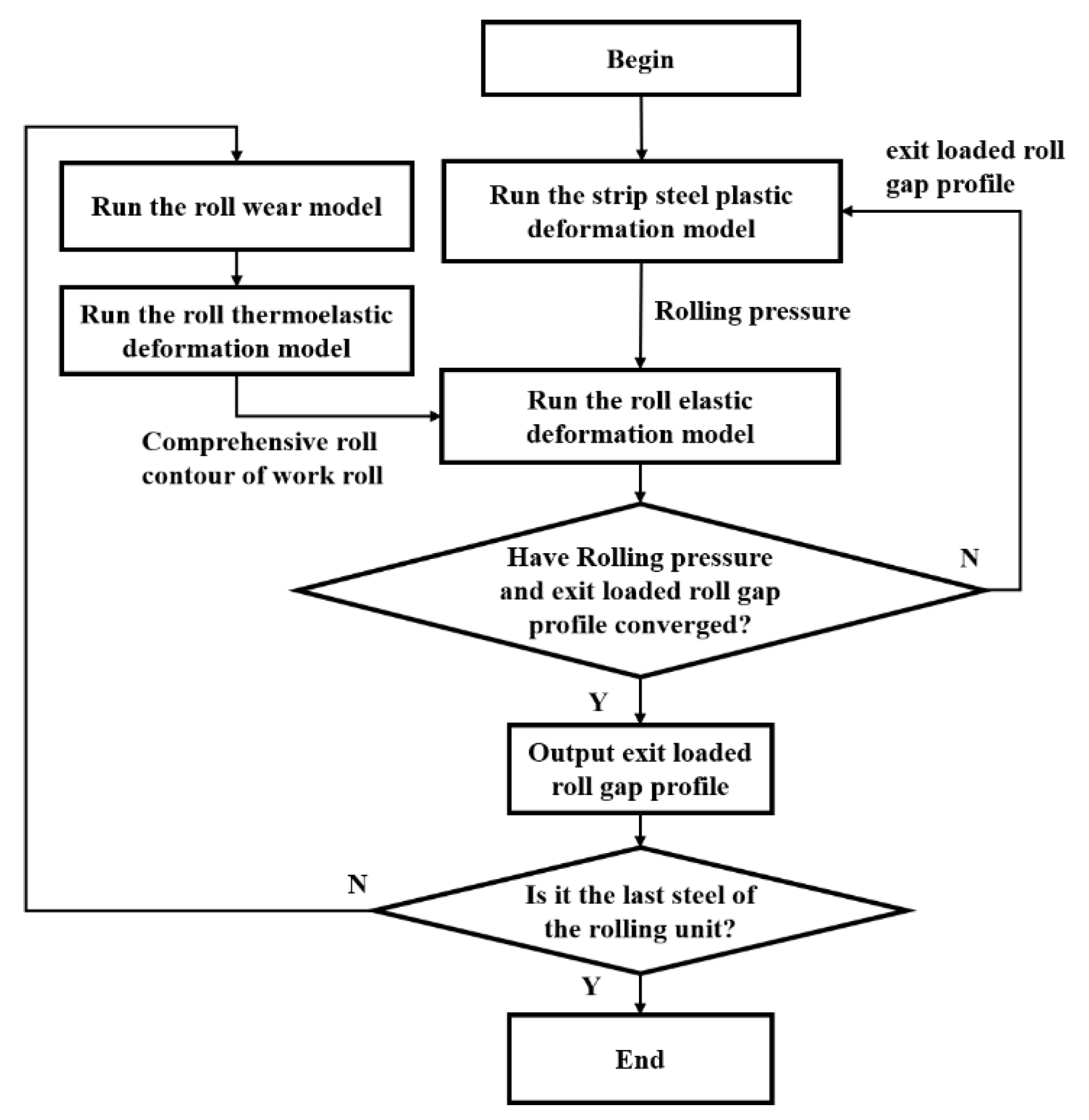
3.3. Rolls-Strip Integrated Model

The rapid calculation model of rolls-strip is established to calculate the influence of roll wear, thermal contour, and elastic deformation of rolls on strip shape. In order to reduce the calculation time and ensure the calculation accuracy, the quasi-three-dimensional assumption conditions suitable for thin strip rolling obtained by progressive analysis method are adopted in the strip model [18]. The strip model calculation process is shown in Figure 4. Firstly, the force balance equation, geometric equation, constitutive equation of the metal microelement in the deformation zone, and the front tension equation in the boundary zone are combined to decouple and eliminate the variables. Then, the nonlinear equation is linearized, and the variance is discretized by the finite difference method. Considering the boundary conditions, all the discrete equations are combined into linear equations and solved by SuperLU decomposition method. Finally, the solutions of the original nonlinear equations are obtained by iteration.
The rolls model adopts the fast rolls deformation model that is improved based on the influence function method [19], in which the bending deformation calculation is based on the difference method of the classical beam theory. The flattening calculation adopts the influence function method, which can realize the fast and high-precision solution of the deformation of the 4-high mill. The coupling calculation steps are shown in Figure 5. Firstly, we assume an initial roll contact surface shape, calculate the rolling force distribution from the rolling model, and transfer it to the rolls model. Then, the rolls model calculates the bending and flattening under this rolling force distribution and obtains the new contact surface shape, which is transferred to the strip model. Finally, the above iterative steps are repeated until the change of contact surface and rolling force is less than the given threshold value. In addition, when updating the contact surface and rolling force, the relaxation coefficient method is used to ensure the stability of the algorithm.

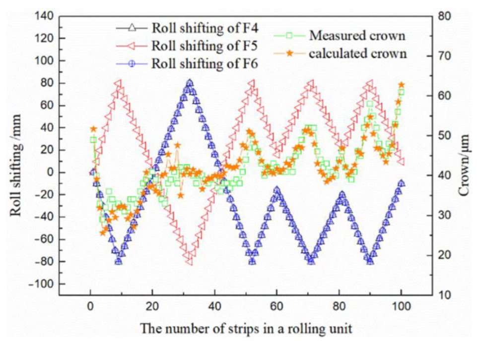
3.4. Model Validation

Combined with the principle of roll elastic deformation and the principle of rolled piece plastic deformation, the relevant knowledge of heat transfer and the basic formula of roll wear, a C++ program is written to build a simulation model that can simulate and calculate the rolling state and shape of a rolling unit. The accuracy of the model was verified by the actual condition under the fixed amplitude roll shifting strategy. The steel is SPHC, and the actual rolling force of each stand is shown in Figure 6. The deviation between the simulation results of the numerical model and the actual value is 5.91%. Figure 7 shows that the fluctuation trend of strip crown calculated is consistent with that of actual crown, which fully verifies the reliability of the model.

4. Development of Double Attenuation Asynchronous Roll Shifting Strategy

4.1. Design Principles

The measured data in Figure 2 shows that the constant amplitude roll shifting strategy adopted by the production line will cause the strip crown to fluctuate periodically with the roll shifting position in the middle and later stages of the rolling unit. When the roll shifting position is close to the zero position, the strip crown is small; multiple stands are at the same roll shifting limit position (including the maximum position and the minimum position), and the strip crown is large. The crown fluctuation is closely related to the uneven wear of rolls and the coincidence of uneven wear positions between downstream stands. Based on the analysis of the causes of strip crown fluctuation, the design principle of dual attenuation asynchronous roll shifting strategy is proposed. Double attenuation refers to roll shifting amplitude attenuation and roll shifting step attenuation of three downstream stands. Asynchronous means that there is a phase difference in roll shifting position of three downstream stands, avoiding a significant increase in crown when each stand moves to the limit position at the same time.
According to the design principle of double attenuation asynchronous roll shifting strategy, it is necessary to satisfy the asynchronous roll shifting position among the three stands. Therefore, Fid is defined to make the three stands enter the asynchronous state when calculating the initial roll shifting position. The wear caused by reaching the higher edge of the roll when the roll shifting position is limited should be reduced, and then it should more easily lead to the sharp increase in strip crown near the limit position of work roll shifting. L is defined to attenuate the limit amplitude of roll shifting, so that the roll will not reach the limit position of the previous cycle in the next roll shifting cycle. In addition, in order to ensure the uniform wear in the roll shifting cycle as much as possible, q is defined to perform the number of roll shifting steps in each roll shifting cycle.

4.2. Roll Shifting Strategy

According to the design principle of double attenuation asynchronous roll shifting strategy, the roll shifting process is expressed by mathematical formula, as shown in the following Equations (4)–(6).
s = ( - 1 ) i + 1 × { L q × n T n T q - L q × ( n T - 2 q ) q < n T 3 q L q × ( n T - 4 q ) n T > 3 q
L = { L 0 n + F i d < n 0 L 0 + ( L 1 - L 0 ) × n + F i d - n 0 n 1 - n 0 n + F i d n 0
n T = ( n + F i d ) 4 q 1
where s is the roll shifting position of each strip, mm; L is the amplitude of roll shifting, mm; n is the number of pieces of the current strip in the rolling unit, starting from 1; q is the number of roll shifting steps from 0 to the limit position; nT is the number of roll shifting steps in the rolling cycle; L0 is the initial roll shifting amplitude, mm; L1 is the final roll shifting amplitude, mm; n0 is the number of strip, which amplitude begins to decay; n1 is the number of the last strip; i is the stand number, i = 4,5,6; and Fid is the number of strips needed to indicate the distance between the initial roll shifting position and the roll shifting zero point of the downstream stand.

4.3. Effect of Roll Shifting Strategy on Strip Crown Fluctuation

4.3.1. Basic Simulation Conditions

Based on the strip crown calculation model established in the previous section, the simulation analysis is performed for the parameters in the double attenuation asynchronous roll shifting strategy, and the influence of the amplitude attenuation and step attenuation parameters in the roll shifting strategy on the strip crown fluctuation of the whole rolling unit is analyzed. In the simulation, 100 strips are set in the whole rolling unit. Considering the characteristics of mass production of the same specification in DSCCR production line, the width of 100 strips is set to 1220 mm, and the steel is SPHC. The basic conditions, such as reduction in and rolling force of each stand, are shown in Table 1.

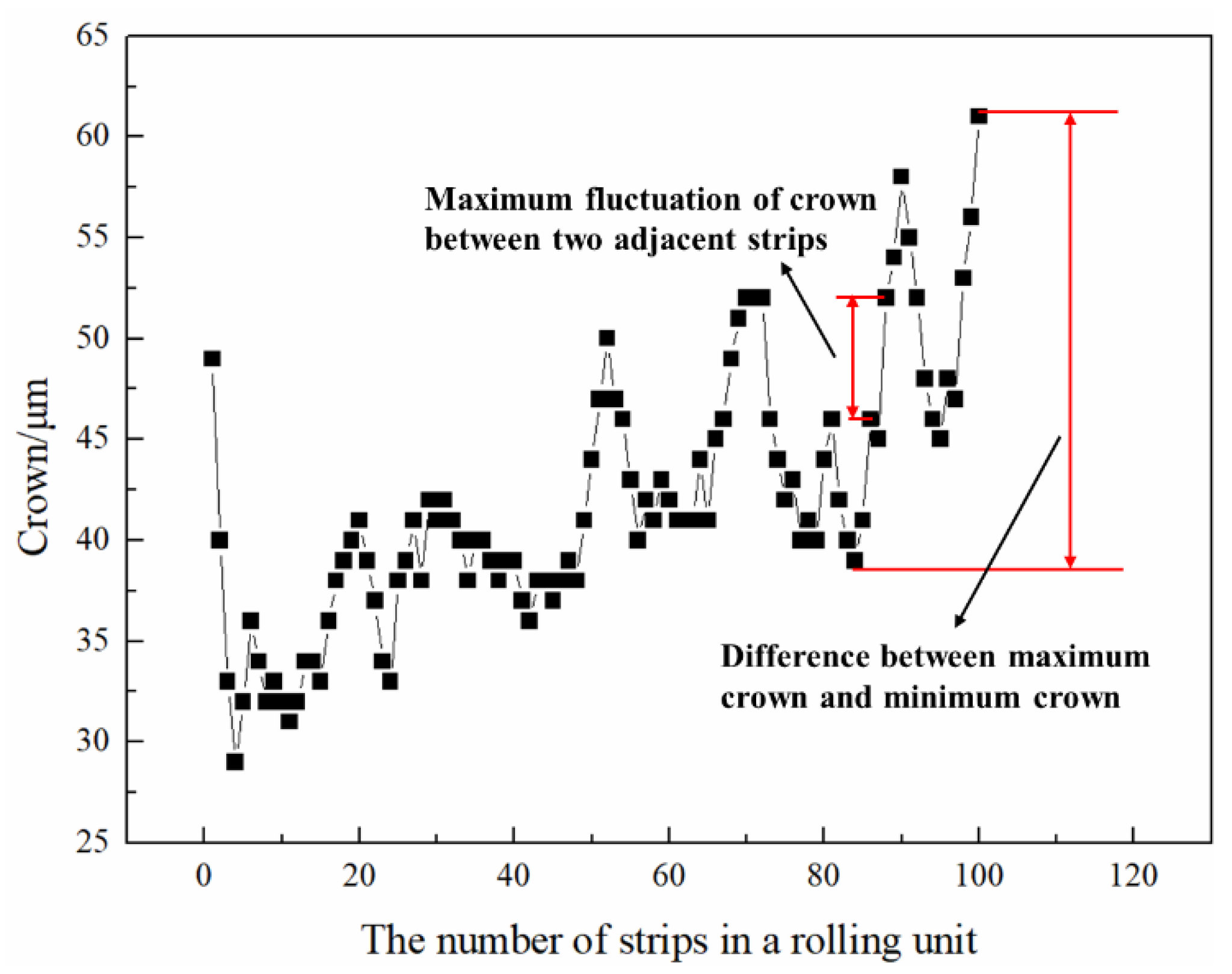
4.3.2. Definition of Evaluation Index

In order to measure the ability of roll shifting strategy to control strip crown stability in the whole rolling unit, it is necessary to quantitatively analyze crown fluctuation and roll wear. In this study, the crown of each strip is C40, which is the difference between the thickness of the middle part of the strip and the average thickness of the two sides 40 mm away from the edge. The following two indexes are defined to evaluate the effect of roll shifting strategy on crown fluctuation, including the maximum crown fluctuation between two adjacent strips after rolling 50 strips and the difference between the maximum crown and the minimum crown, as shown in Figure 8. According to the wear characteristics of the work roll, the high point of the wear roll contour is defined as the maximum deviation between the wear amount of the middle part of the roll and the wear amount of the edge. The maximum wear crown of the work roll of the end stand is within the width of the strip. These two wear roll contour characteristics are used as the quantitative indexes to evaluate the wear degree of the work roll, as shown in Figure 9. The double attenuation asynchronous roll shifting strategy can change the form of roll shifting according to the number of strips in the roll shifting cycle and the shifting amplitude at the end of a rolling unit. To influence two kinds of roll shifting strategy parameters on strip crown fluctuation and roll wear degree, the evaluation indexes of two kinds of roll shifting strategy parameters at different values were studied.

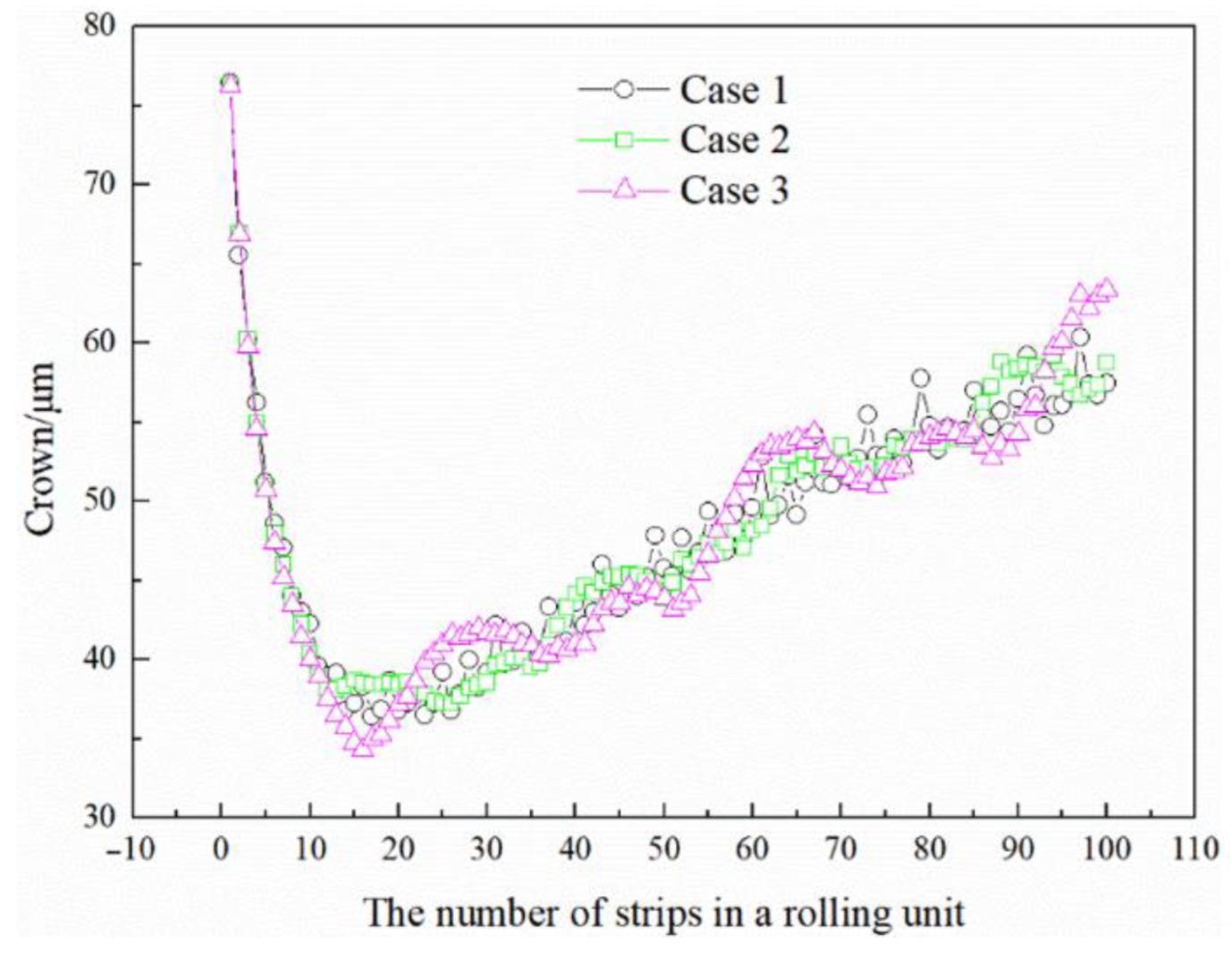
4.3.3. Effect of Strip Number on Strip Crown Fluctuation in a Roll Shifting Cycle

In order to ensure the uniformity of work roll wear and the stability of strip crown, it is necessary to perform multiple periodic roll shifting in a rolling unit. The number of strips in each cycle determines the position interval of two adjacent strips. In order to explore the influence of the number of strips in a roll shifting cycle on the strip crown fluctuation under the double attenuation roll shifting strategy, the number of strips in the roll shifting cycle is set to 3, 6, and 9, respectively, corresponding to Case 1, Case 2, and Case 3, when the initial number of strips is set to 30 and the final roll shifting amplitude is set to 50 mm. The simulation results are shown in Figure 10, where the roll crown is larger at the initial stage of rolling because of the smaller thermal crown at the initial stage of rolling. With the increase in roll crown, strip crown begins to decrease. Because of the roll shifting, the wear in the middle of the roll is greater than that in the edge area, so the strip crown increases. In the actual industrial production, the control system will adjust the roll bending force of each stand and the CVC roll shifting of the upstream stand to control the increase trend in strip crown. However, in order to ensure the consistency of other conditions for comparison, the roll bending force of each stand used in the whole rolling unit is the same as the roll shifting of upstream stand CVC; therefore, the strip crown has an obvious increasing trend. In addition, when the number of roll shifting strips is small, the difference of roll shifting between two adjacent strips is shown to increase, and the uniformity of roll wear becomes worse, which leads to more severe fluctuation of strip crown. The increase in roll shifting strips in the cycle will enhance the uniformity of roll wear and also make the temperature of the edge and middle of the roll more uniform; thus, by reducing the roll thermal contour, the strip crown also will increase significantly.
Figure 11 shows that the maximum values of strip crown fluctuation at the middle and later stages are 15.0 μm, 12.8 μm, and 20.2 μm, respectively. The crown fluctuations of two adjacent strips are 3.94 μm, 2.16 μm, and 2.19 μm, respectively, which indicates that when the number of stirps in the roll shifting cycle is 3 or 9, the difference between the maximum crown and the minimum crown in the middle and later stages is large. When the number of stirps in the roll shifting cycle is small, the uniformity of roll shifting cannot be well guaranteed, resulting in poor uniformity of roll wear. When the number of strips in the roll shifting cycle is large, the roll wear is more uniform. At the same time, when the thermal crown caused by the temperature difference between the edge and the middle of the roll also is reduced, the strip crown also is increased. The high point of wear roll shape and the maximum value of wear crown, as shown in Figure 12, is below the high point of wear roll shape between two adjacent strips, which are 178.9 μm, 170.8 μm, and 162.7 μm, respectively. The maximum values of wear crown are 35.5 μm, 35.8 μm, and 32.9 μm, respectively, which indicates that with the increase in the number of strips in the roll shifting cycle and the wear uniformity of work roll are obviously improved. Therefore, considering the factors of wear contour, thermal contour, and roll system deflection, the number of strips in the roll shifting cycle cannot be set too small or too large.

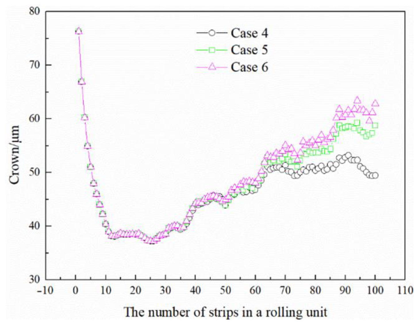
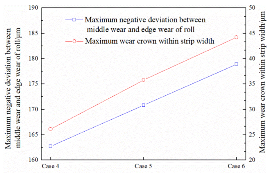
4.3.4. Effect of Roll Shifting Amplitude on Strip Crown Fluctuation

The shifting amplitude at the end of a rolling unit is an important factor that affects the amplitude of roll shifting. In order to avoid the significant increase in crown caused by small edge wear when the work roll reaches the limit position, it is necessary to continuously attenuate the shifting amplitude. In a rolling unit, the amplitude of roll shifting needs to be attenuated, which will not only affect the limit position of roll shifting in each cycle but also affect the roll shifting position interval of two adjacent strips. In order to study the influence of the shifting amplitude at the end of a rolling unit on strip crown fluctuation under the double attenuation roll shifting strategy, the initial number of roll shifting strips is 30, and the number of strips in the shifting cycle is 6. The roll shifting amplitude at the end of a shifting unit is set to 20 mm, 50 mm, and 70 mm, respectively, corresponding to Case 4, Case 5, and Case 6. The simulation results are shown in Figure 13, which shows that the three roll shifting amplitudes have obvious differences on the strip crown in the middle and later stages. With the increase in the shifting amplitudes, the strip crown gradually increases in the middle and later stages. When the roll shifting amplitudes are small, the strip crown changes are less obvious. This is because when the roll shifting amplitudes at the end stage are small, the difference of roll shifting amplitudes between adjacent roll shifting cycles increases, which is more conducive to avoid the area with less edge wear to ensure the stability of strip crown.
Figure 14 shows that with the increase in the roll shifting amplitude in a shifting cycle, the maximum values of strip crown fluctuation at the middle and later stages are 9.3 μm, 14.7 μm, and 16.7 μm, respectively. The crown fluctuations of two adjacent strips are 1.5 μm, 2.2 μm, and 2.3 μm, respectively, which indicates that the increase in the shifting amplitude will reduce the roll shifting range of work roll and the wear uniformity and temperature uniformity of work roll. Finally, the fluctuation of strip crown increases. Figure 15 shows the indexes of work roll wear contour and the highest wear point and the maximum wear crown in the middle and later stages. The increase in the shifting amplitude is not conducive to the uniform wear of work roll. Therefore, on the premise of ensuring the allowance for roll shifting, the smaller end roll shifting amplitude is better.

5. Application Effect of Double Attenuation Roll Shifting Strategy in Field

The double attenuation asynchronous roll shifting strategy has been applied in DSCCR production line. The test conditions of the double attenuation asynchronous roll shifting strategy are the same as those of the original roll shifting strategy. The test stand is F4~F6 finishing mill, the steel grades are all SPHC, the inlet thickness is 95 mm, the outlet thickness is 3 mm, and the width is 1220 mm. Strip crown data was measured with a multifunction measuring instrument from IMS. The roll shifting form and measured crown are shown in Figure 16. The number of roll shifting strips in a cycle is 6, and the roll shifting amplitude at the end of a rolling unit is 50 mm. The crown fluctuation is effectively controlled. From the running state, the crown stability is significantly enhanced, and the wear uniformity is significantly improved. In order to show the optimization effect of double attenuation asynchronous roll shifting strategy more intuitively, Figure 17 compares the crown fluctuation of double attenuation asynchronous roll shifting in a rolling unit with that of the original strategy. In the middle and later stage of rolling unit, the crown fluctuation of the strip is greatly improved, and the maximum crown fluctuation is reduced from 19 μm to 15 μm, a decrease of 21.05%. The maximum crown fluctuation of two adjacent strips decreased from 7 μm to 5 μm, a decrease of 28.57%. In addition, Figure 18 shows the comparison of work roll wear contour of the downstream stands. The work roll wear is shown to be more uniform under the double attenuation asynchronous roll shifting strategy.

6. Conclusions

(1)
The simulation model of multistand continuous rolling is established by numerical method, which integrates wear contour, thermal contour, and rolls-strip deformation. The reason for strip crown fluctuation in rolling unit is revealed by simulation calculation under actual working conditions.
(2)
In order to solve the problem of large strip crown fluctuation in batch production of the same width and thin gauge in hot rolling line, a double attenuation asynchronous work roll shifting strategy is proposed. The number of roll shifting strips in different periods and the amplitude of roll shifting at the end of a rolling unit are simulated. When the number of roll shifting strips is small or large in a shifting cycle, it is not conducive to the stability of strip crown. Based on ensuring the allowance of roll shifting, the smaller the value, the more beneficial it is to the stability of strip crown and the uniformity of roll wear.
(3)
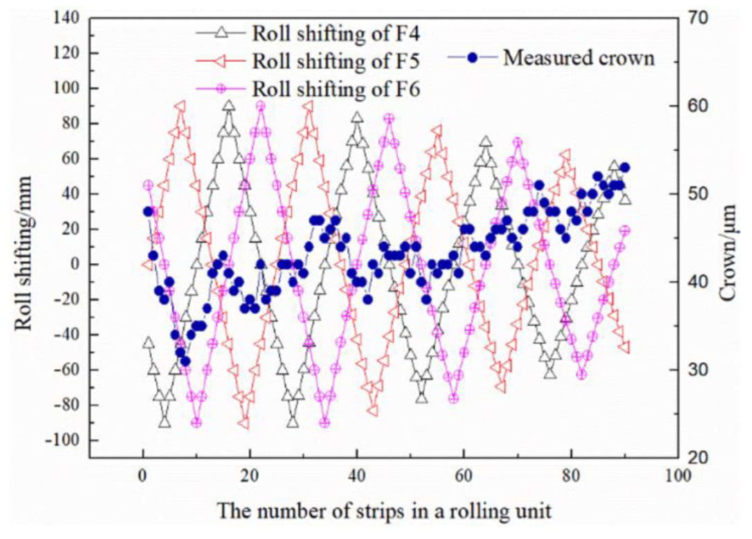
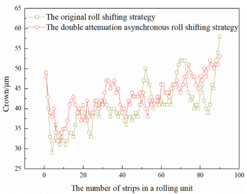
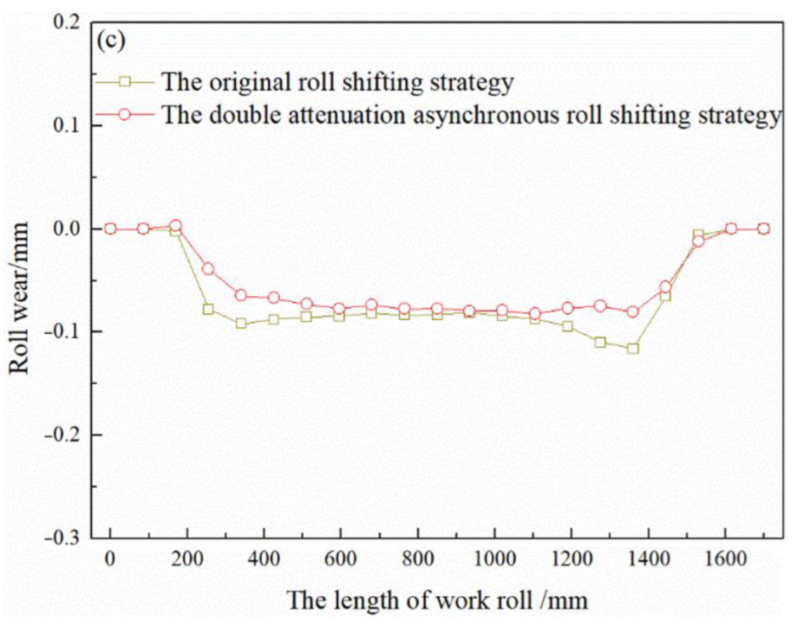
The strategy of double attenuation asynchronous work roll shifting has been applied in the industrial field. From the use of the new strategy, the maximum crown fluctuation in the rolling unit decreased by 21.05%, and the maximum crown fluctuation of adjacent strips decreased by 28.57%. At the same time, the work roll wear was more uniform.

Author Contributions

Conceptualization, Z.L. and S.W.; methodology, Z.L.; software, Z.L. and C.Y.; validation, Z.L. and G.Z.; formal analysis, Z.L., Z.Q., and G.Z.; investigation, L.G. and D.Z.; resources, A.H.; data curation, Z.L., Z.Q. and L.G.; writing—original draft preparation, Z.L. and G.Z.; writing—review and editing, S.W. and Z.Q.; visualization, C.Y.; supervision, S.W.; project administration, Z.Q.; funding acquisition, S.W., D.Z., and A.H.; All authors have read and agreed to the published version of the manuscript.

Funding

The authors gratefully acknowledge the support from the National Natural Science Foundation of China (No. 51774139) and the Natural Science Foundation of Hebei province (E2020209014).

Institutional Review Board Statement

Not applicable.

Informed Consent Statement

Not applicable.

Data Availability Statement

Not applicable.

Acknowledgments

The authors would like to express sincere gratitude to the National Engineering Research Center for Advanced Rolling Technology for providing the simulation equipment and the Hunan Xiangtou Goldsky Titanium Metal Co., Ltd. for providing the test opportunity.

Conflicts of Interest

The authors declare no conflict of interest.

References

  1. Muntin, A.V. Advanced technology of combined thin slab continuous casting and steel strip hot rolling. Metallurgist 2019, 62, 900–910. [Google Scholar] [CrossRef]
  2. Kang, Y.; Peng, T.; Zhu, G. Progress and trend on hot wide strip endless rolling technology. Iron Steel 2019, 54, 1–8. [Google Scholar]
  3. Arvedi, G.; Mazzolari, F.; Siegl, J.; Hohenbichler, G.; Holleis, G. Arvedi ESP first thin slab endless casting and rolling results. Ironmak. Steelmak. 2010, 37, 271–275. [Google Scholar] [CrossRef]
  4. Lee, J.; Kang, Y.; Won, C.S.; Son, S.L.; Horii, K. Development of a new solid-state joining process for endless hot rolling. Iron Steel Technol. 2009, 51, 48–54. [Google Scholar]
  5. Hoen, K.; Klein, C.; KrMer, S.; Chung, J.S. Recent development of thin slab casting and rolling technology in a challenging market. BHM Berg-und Hüttenmännische Mon. 2016, 161, 415–420. [Google Scholar] [CrossRef]
  6. Zheng, X. Endless strip production technoloqy in Rizhao steel company. Metall. Equip. 2016, 44, 43–46. [Google Scholar]
  7. Tian, P.; Kang, Y.L.; Zhu, J.T.; Qin, Z.; Zheng, X.T.; Wang, F. Achievements of endless strip production in Rizhao steel. Mater. Sci. Forum 2019, 4734, 344–350. [Google Scholar] [CrossRef]
  8. Yang, W.; Dong, Z.; Zhang, J. FGC control technology of hot strip endless rolling. Iron Steel 2020, 37, 70–74. [Google Scholar]
  9. Liu, X.; Ding, X.; Guo, L. Continuous Rolling Method and Device Based on MCCR. CN111515249A, 15 April 2020. [Google Scholar]
  10. Shao, J.; He, A.; Yang, Q.; Guo, H.W. Varying shifting stroke strategy of work rolls in hot rolling. Chin. J. Eng. 2011, 33, 93–97. [Google Scholar]
  11. He, H.; Wang, X.; Yang, Q.; Sun, X.; Xiao, J.; Liu, Y.; Song, G. Smart-shifting strategy of work rolls for downstream stands in hot rolling. Ironmak. Steelmak. 2020, 47, 512–519. [Google Scholar] [CrossRef]
  12. Yao, C.; He, A.; Shao, J.; Zhang, Y.J.; Zhao, H.S. Edge drop and high spot control of hot-rolled non-oriented electrical steel strip by taper roll shifting strategy. Ironmak. Steelmak. 2020, 47, 138–144. [Google Scholar] [CrossRef]
  13. He, A.; Zhang, Q.; Xu, J. Genetic algorithms of work roll wear model for hot rolling. Iron Steel 2000, 21, 58–61. [Google Scholar]
  14. Cao, J.; Zhang, J.; Gan, J.; Su, Y.; Tang, B.; Yan, T. Work roll wear prediction model of non-oriented electrical steel sheet in hot mills. J. Univ. Sci. Technol. Beijing 2006, 18, 286–289. [Google Scholar]
  15. Kong, X.; Shi, J.; Xu, J.; Wang, G.D. Wear prediction of roller for hot mill during service. J. Northeast. Univ. 2002, 23, 790–792. [Google Scholar]
  16. Guo, X.; He, A.; Shao, J.; Zhou, B.; Li, Q. Modeling and simulation of subsectional cooling system during hot aluminum rolling. J. Mech. Eng. 2013, 49, 70–74. [Google Scholar] [CrossRef]
  17. Wang, L.S.; Yang, Q.; He, A.R.; Zheng, X.; Yu, H.R. Improvement of prediction model for work roll thermal contour in hot strip mill. J. Cent. South Univ. Technol. 2010, 17, 1251–1257. [Google Scholar] [CrossRef]
  18. Yao, C.; He, A.; Shao, J.; Zhao, J. A real-time quasi-3D metal flow model for hot strip rolling. Int. J. Mech. Sci. 2019, 159, 91–102. [Google Scholar] [CrossRef]
  19. Kong, F.; He, A.; Shao, J. Research on rapid online calculation methods of roll stack deformation. J. Mech. Eng. 2012, 48, 121–126. [Google Scholar] [CrossRef]
Figure 1. The layout of Tangshan Donghua DSCCR production line.
Metals 12 01265 g001
Figure 2. The measured crown in a rolling unit.
Metals 12 01265 g002
Figure 3. The mesh generation of roll temperature field.
Metals 12 01265 g003
Figure 4. The strip model calculation process.
Metals 12 01265 g004
Figure 5. Calculation process of rolls-strip integrated model.
Metals 12 01265 g005
Figure 6. The measured rolling force of each stand.
Metals 12 01265 g006
Figure 7. Verification of calculation accuracy of rolls-strip integrated model.
Metals 12 01265 g007
Figure 8. Crown fluctuation quantitative index.
Metals 12 01265 g008
Figure 9. Characteristic value of wear roll contour.
Metals 12 01265 g009
Figure 10. Strip crown fluctuation in a rolling unit with different shifting number of strips.
Metals 12 01265 g010
Figure 11. Strip crown fluctuation index in the middle and later stage of rolling unit.
Metals 12 01265 g011
Figure 12. The indexes of wear contour under different number strips of a rolling cycle.
Metals 12 01265 g012
Figure 13. Strip crown distribution in a rolling unit with different roll shifting amplitude.
Metals 12 01265 g013
Figure 14. Strip crown fluctuation index in middle and later stage of rolling unit.
Metals 12 01265 g014
Figure 15. The indexes of roll wear contour under different amplitude at the end of a rolling unit.
Metals 12 01265 g015
Figure 16. The double attenuation asynchronous roll shifting strategy and measured strip crown.
Metals 12 01265 g016
Figure 17. Comparison of strip crown after double attenuation asynchronous roll shifting strategy.
Metals 12 01265 g017
Figure 18. Comparison of work roll wear contour of downstream stands: (a) F4; (b) F5; and (c) F6.
Metals 12 01265 g018aMetals 12 01265 g018b
Table 1. Model simulation conditions.
NameStand
F1F2F3F4F5F6
Entry thickness/mm3518.7810.816.854.733.58
Exit thickness/mm18.7810.816.854.733.583.02
Bending force /t73.542.569.587.562.525
Entry temperature /°C107210251003981958933
Rolling speed/m⋅s−10.751.282.032.984.014.89
Rolling force /t16892139195114611181838
Publisher’s Note: MDPI stays neutral with regard to jurisdictional claims in published maps and institutional affiliations.

