Article

Development of Desirable Fine Ferrite Grain Size and Random Second Phase Dual-Phase Steel Microstructures Using Composition and/or Processing Modifications

1
Warwick Manufacturing Group (WMG), University of Warwick, Coventry CV4 7AL, UK
2
Tata Steel R&D, Warwick Technology Centre, Voyager Building, Coventry CV4 7EZ, UK
*
Author to whom correspondence should be addressed.
Metals 2022, 12(7), 1158; https://doi.org/10.3390/met12071158
Submission received: 10 May 2022 / Revised: 28 June 2022 / Accepted: 1 July 2022 / Published: 7 July 2022
(This article belongs to the Special Issue Novel Steel Compositions and Processing Technologies)

Abstract

:
Microstructural morphology is known to have a significant impact on the mechanical properties of dual-phase steels. A fine ferrite grain size and random distribution of small second phase islands are desirable to provide superior isotropic properties compared to the banded second phase distribution that is typical for this type of steel. A rapid alloy prototyping (RAP) facility has been used to investigate three different DP 800 variants by systematically varying the compositions and/or process parameters compared to the ‘standard’ DP800 composition and processing that gives a banded microstructure. For Variant 1, the heating rate during the annealing cycle after cold rolling varied between 0.65 and 30 °C/s for the 45%, 60% and 75% cold reduction samples. It was found that a cold reduction of 75% and heating rate of 15 °C/s resulted in the microstructure that can give the best combination of strength and ductility because of the fine grain size and high martensite volume fraction. For Variant 2, the effect of changing the hot rolled (HR) microstructure (ferrite–pearlite, ferrite–bainite or martensite) on the final microstructure was investigated. Both the ferrite–50% bainite and fully martensite/bainite HR materials for all cold reductions resulted in annealed microstructures with necklace martensite morphology and finer ferrite grains compared to the ferrite–pearlite HR material, which gave a typical banded ferrite–martensite microstructure with a coarser ferrite grain size. For Variant 3, the Mn content was reduced, and increased Nb was used to achieve higher pancaking during the hot rolling stage, which refined ferrite grains in the HR condition with the same hardness. After annealing with the standard parameters only the 45% cold-reduced material produced a finer ferrite grain size than the standard material, whereas the 60% and 75% cold-reduced samples required a higher heating rate to achieve finer ferrite grain sizes due to rapid recrystallisation and growth kinetics.

1. Introduction

The microstructure of dual-phase (DP) steels consists of soft ferrite and hard martensite phases, giving these steels an excellent combination of strength and ductility. The mechanical properties of these steels are not only dependent on the volume fractions and the grain sizes of these phases but also have a large dependency on the distribution and the morphology of the martensite islands [1,2]. One of the major damage mechanisms in DP steel comes from interphase decohesion between the ferrite and martensite phases due to their large strength differences, causing strain incompatibilities, leading to premature failure [3]. It is known that this problem is mainly seen in DP steels with high carbon martensite (high strength relative to ferrite) and martensite in a banded and/or blocky morphology [4]. Banded or blocky microstructures in DP steels can be the result of multiple factors. Typically, it is a result of either inherent segregation favourably forming austenite in solute-rich regions (typically Mn) or as a result of transformation in a deformed microstructure. This type of banded or blocky morphology is highly detrimental to the mechanical properties. Firstly, it leads to a high localised strain at the vicinity of the martensite phase and therefore is not ideal for producing a good combination of strength and ductility. Tasan et al. reported that the ferrite grains near the blocky martensite will experience a large macroscopic strain even at lower loads, causing voids and leading to failure before the whole material reaches its strain-hardening capacity [5]. Moreover, the banded martensite morphology increases the anisotropy in the material’s mechanical properties by generating large differences in the tensile strengths and total elongations [6]. Ismail et al. reported that, in a banded DP steel microstructure, the tensile strength along the rolling direction will be highest (861 MPa), followed by the transverse direction (827 MPa) and lowest along the 45° angle (761 MPa). This anisotropy in the mechanical properties is not desirable in an industrial commercial product. Additionally, a banded martensite morphology decreases the hole expansion ratio or edge stretching capability of the DP steels; for example, Keeler et al. reported that the hole expansion ratio (HER) decreased from 0.97 in a non-banded microstructure to 0.7 in a banded microstructure [7].
During the annealing of cold rolled DP steel, the strip is heated to an inter-critical temperature, and both recrystallisation and phase transformation occur. For a standard inter-critical annealing cycle [7] and high cold rolling reductions, ferrite recrystallisation typically occurs before the Ac1 temperature, followed by some grain growth, prior to austenite transformation. However, at higher heating rates/low rolling reductions, the progress of ferrite recrystallisation can be shifted into the inter-critical region, thereby enabling a significant overlap between ferrite recrystallisation and austenite formation processes [1,8,9,10]. It has been reported that, with an increase in the overlap of these processes, the severity of martensite banding increases [1,8,11], resulting in increased anisotropy and a reduced edge stretching capability. Further, some studies also suggested that, at extremely high heating rates, very fine martensite islands can also form [2,9], giving superior mechanical properties. Azizi et al. used this approach (1, 50 and 300 °C/s) to produce ultra-fine dual-phase steels, which resulted in an increase of tensile strength by 150 MPa whilst having a similar elongation value [2]. Lolla et al. also used this approach (~500 °C/s) to produce ultra-high strength (1600 MPa) dual-phase steel with an acceptable ductility of 10% [9]. These heating rates are very high and cannot be used in conventional industrial production. However, the heating rate during industrial inter-critical annealing can vary due to differences in the line speed, furnace length, strip thickness and type of furnace. It has been reported that annealing lines with direct fire furnaces produce heating rates of up to 50 °C/s, whereas annealing lines with radiant tube furnace produce significantly lower heating rates in the range of 1–10 °C/s [12].
The effect of a hot rolled microstructure on the final DP steel microstructure is also a subject of interest in the published literature [13,14]. This is mainly due to the inheritance of the microstructural features from the hot rolling stage to the final DP steel microstructure. For instance, Kulakov et al. systematically showed the inheritance of banded pearlite morphology from the hot rolled ferrite–pearlite microstructure to the banded martensite morphology in the final DP steel microstructure [14]. Moreover, a finer ferrite grain size from the hot rolling stage is expected to be carried over into the cold rolled and the annealed microstructure via a finer recrystallised ferrite grain size. In this regard, Nb is increasingly becoming an important addition to DP steels, as it increases the Temperature of No Recrystallisation (TNR) temperature [15], which, in turn, increases the amount of pancaking of austenite grains during the final passes of hot rolling. This leads to an increased austenite grain boundary area and consequentially increasing the number of potential nucleation sites for ferrite leading to a finer ferrite grain size in the hot rolled microstructure.
This paper reports on work utilising these concepts and a rapid alloy processing (RAP) facility to systematically assess three potential process/compositional variations to develop desirable microstructural features in DP steels. The RAP facility has been benchmarked against a commercial DP 800 grade strip to show that representative microstructures and properties can be achieved in the hot rolled, cold-reduced and annealed conditions [16].
These three concepts are:
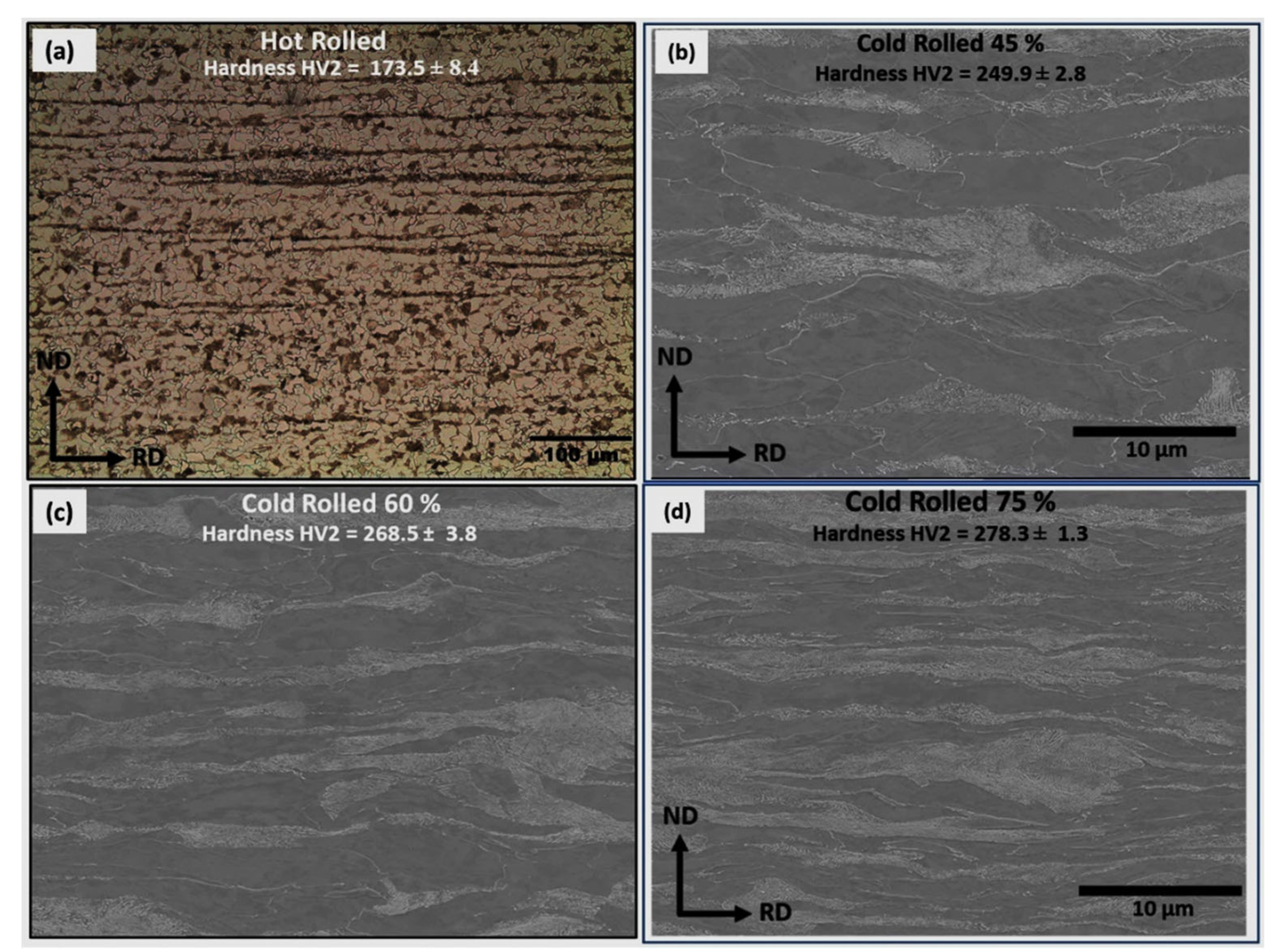
  • Variant 1—Heating Rate Study. By changing the heating rate during annealing for a standard DP steel composition rolled to different cold rolling reductions, then the effect of changing the balance of recrystallisation, grain growth and austenitisation has been assessed.
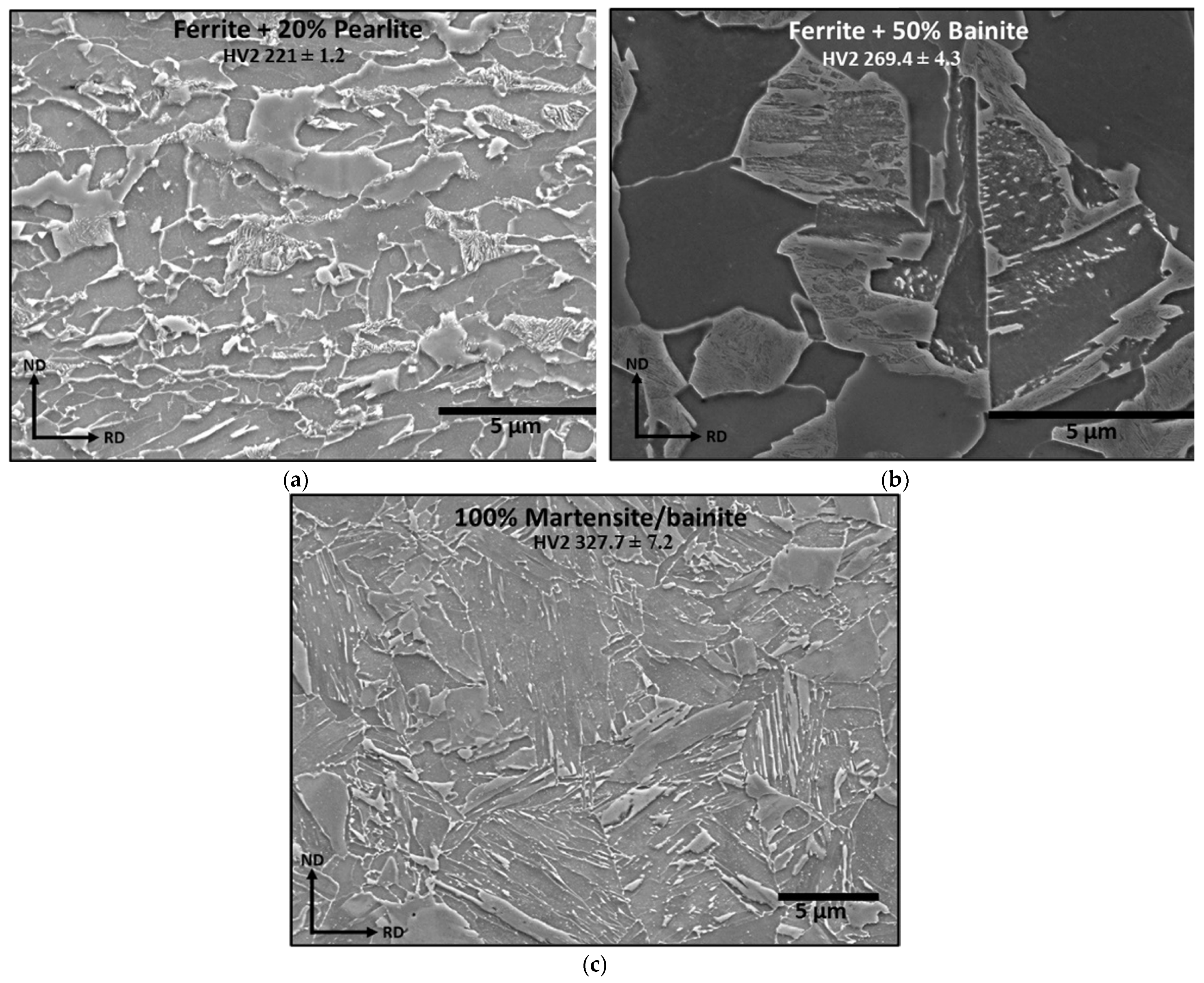
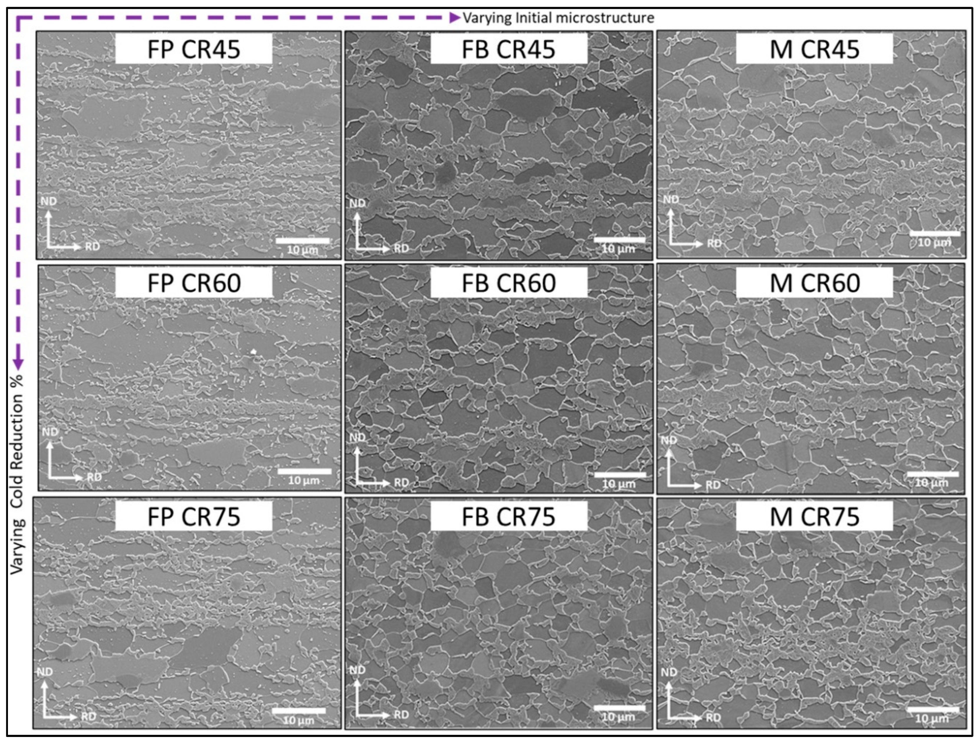
  • Variant 2—Hot Rolled Microstructure Study. Different hot rolled microstructures of ferrite/pearlite, ferrite/bainite and fully martensitic have been produced, and the effect of cold rolling reduction and annealing on the resulting microstructure has been assessed considering the differences in martensite nucleation site locations.
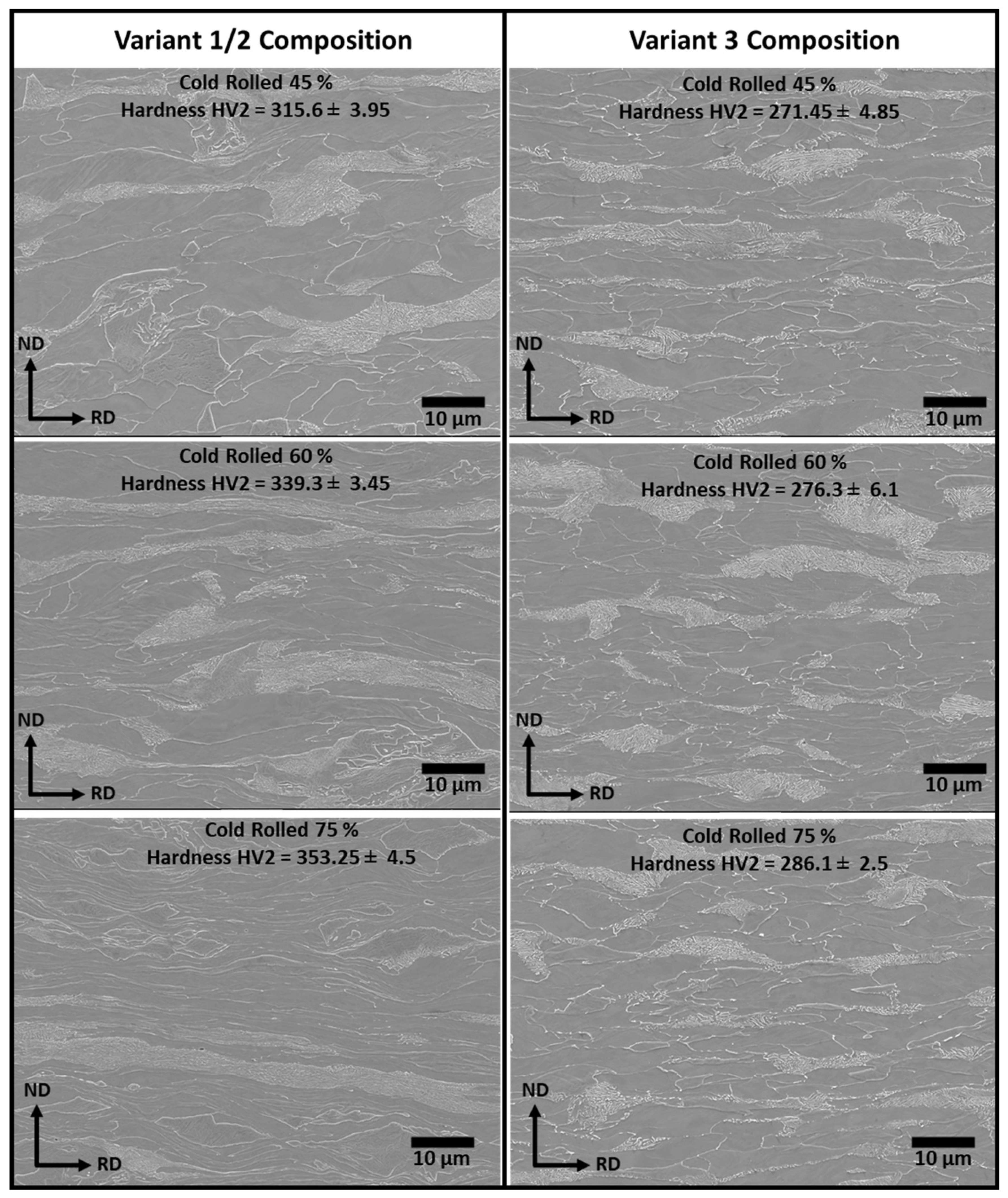
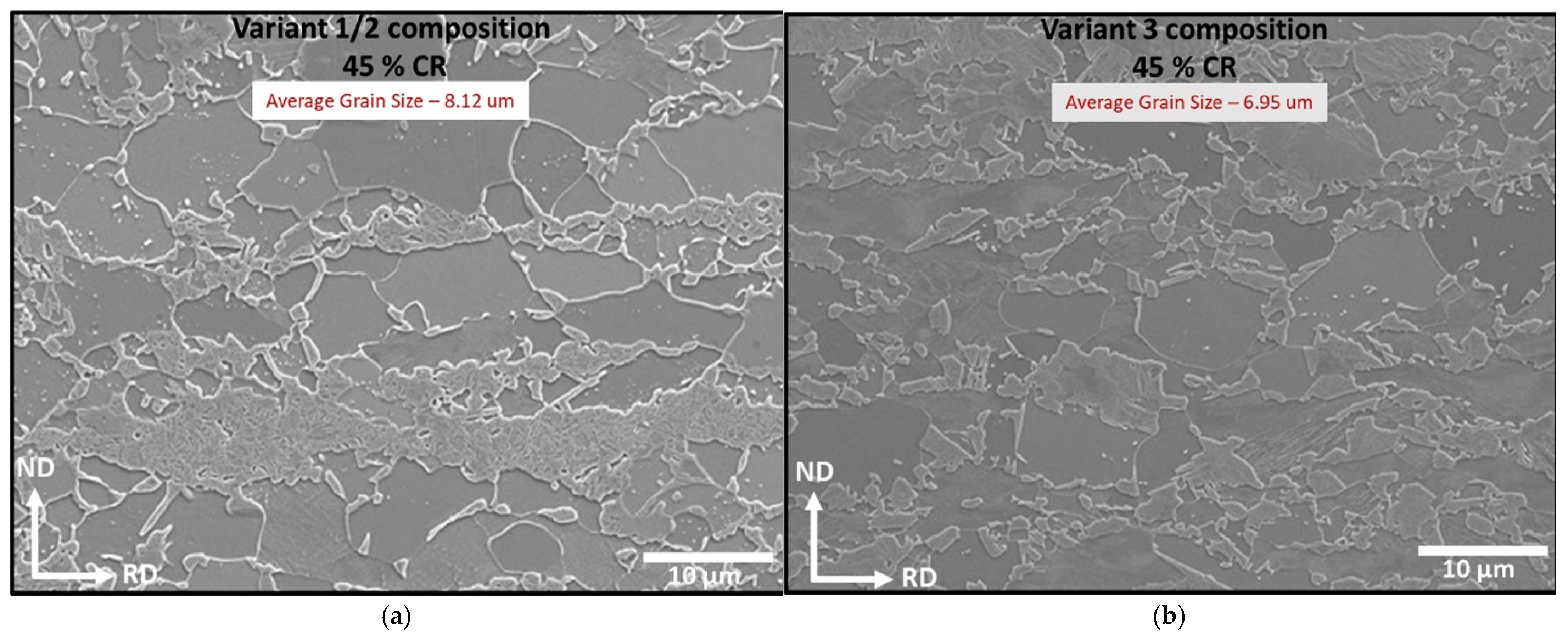
  • Variant 3—Increased Nb Study. Reducing the Mn content and increasing the Nb content has been used to change the hot rolled microstructure (finer ferrite grain size), whilst maintaining the same hardness (balanced increased grain size strengthening and reduced solid solution strengthening). The effect of cold rolling reduction and annealing on the resulting microstructure has been assessed, accounting for the reduced Mn segregation and finer grain size affecting the martensite nucleation behaviour.

2. Materials

The steel compositions for this study are selected to be in the range of commercial DP 800 steels [17]. For Variant 1 and Variant 3, a Consarc vacuum induction (VIM) furnace was used to produce 5-kg casts with ingot dimensions of 220 × 80 × 30 mm. The chemical composition of these casts was measured using Optical Emission Spectrometry (OES) and an ELTRA CS-2000 Carbon Sulphur (C–S) analyser and are shown in Table 1. For the Variant 2 study, a commercial DP 800 3.5-mm-thick hot rolled strip with nominally the same composition as Variant 1 was used as the starting material.

3. Methodology

3.1. Variant 1

After casting, the ingot was hot rolled using a Hille mill, with a too-high configuration. Blocks of 45 mm in length were cut from the ingot and were soaked at 1050 °C for 1 h (homogenised) prior to the first rolling pass and for 5 min between each intermediate pass. Rolling reductions of around 30% were carried out until a final hot rolled thickness of 3.5 mm. After the last hot rolling pass, the strip was allowed to cool quickly in the air until 600 °C, followed by slow cooling to room temperature (24 h) in an alumina Techne FB-08 fluidised bed furnace set at 600 °C. Cold rolling was then carried out to rolling reductions of 45, 60 and 75%.
The cold rolled strips were cut into rectangular samples of 80 × 6-mm dimensions using aqua jet cutting. Heating rates of 0.65 °C/s, 1.2 °C/s, 5 °C/s, 15 °C/s and 30 °C/s were used to simulate the range of heating rates that can be achieved on a commercial continuous annealing line. All the heat treatments were conducted at a peak temperature of 730 °C for a holding time of 150 s, followed by quenching to room temperature at a cooling rate of −50 °C/s. The thermal tests were conducted using an Phoenix Electro-Thermal Mechanical Testing machine (ETMT), which uses induction heating and compressed air to achieve the time temperature profile for a given heat treatment.

3.2. Variant 2

The as-received DP 800 hot rolled strip material was sectioned into 10 × 120-mm sections and were then heat-treated in a Gleeble HDS-V40, where they were heated to 900 °C for 5 min before being cooled either using forced air or water quenched. JMatPro version 13.0 was used to create the CCT curve for this material to determine the cooling conditions required to achieve the desired microstructures and can be seen in Figure 1. Table 2 gives the heat treatment conditions and attained microstructures. After Gleeble heat treatment, the samples were cold rolled to 45, 60 and 75%; then, 10 × 4-mm samples were removed (ensuring from the location corresponding to the isothermal Gleeble heat treatment region) and inter-critically annealed using the Bähr Dilatometer 805 A/D. To obtain similar martensite volume fractions for all the three initial microstructures, the peak inter-critical annealing temperatures were varied. It was found that, for the ferrite–pearlite initial microstructure, an inter-critical annealing temperature of 730 °C was required to achieve the desired 35% second phase, whereas, for the ferrite–50% bainite and fully martensite/bainite, the peak inter-critical annealing temperatures was required to be 750 °C. For all the three microstructures, the heating rate and holding time were kept constant at 1.2 °C/s and 150 s, respectively.

3.3. Variant 3

The 220 × 80 × 30-mm cast was rough rolled to 12 mm before being sectioned into 10 × 20 × 120-mm samples for hot deformation plane strain simulations using the Gleeble HDS-V40 system. For comparison, the material used for Variant 1 was also processed in the same manner to provide benchmark microstructures. It should be noted that the DP800 hot rolled steel used for the Variant 2 trials had a similar composition to Variant 1. For the Gleeble simulations, the samples were heated to 1200 °C for 5 min before following a finishing pass schedule based on commercial temperature strain conditions for the hot rolling strip. The measured temperature and strain history for the deformation schedule are shown in Figure 2. After the Gleeble plane strain hot deformation, the samples were cold rolled to 45, 60 and 75% reduction; then, 10 × 4-mm samples were machined/extracted and heat-treated using Bähr Dilatometer 805 A/D. Whilst the Variant 1/2 composition samples for all cold reductions were heat-treated with a peak temperature of 730 °C and an effective heating rate of 1.2 °C/s; for the Variant 3 cold rolled samples, the peak temperature required was 750 °C, and effective heating rates of 1.2 °C/s and of 10 °C/s were used. The higher peak temperature was selected to achieve the same second phase fraction in the lower Mn Variant 3 steel, and the different heating rates were used to consider the effect of changing the extent of recrystallisation and austenitisation overlap.

3.4. Metallographic Preparation and Analysis

For metallurgical characterisation of all the Variant samples (hot rolled, cold rolled and heat-treated), small-sized samples were cut and mounted (KonductoMet resin) on the RD–ND plane. Depending upon the requirement, the mounted samples were polished using standard metallographic procedures to a finish of 0.05–0.01 μm. For revealing the microstructures, etching was done using the Nital 2% solution for 2–10 s. Nikon Eclipse LV150N was used for optical micrography. FEG JEOL 7800F-SEM equipped with a secondary electron (SE) detector, Energy-Dispersive X-Ray (EDX) detector and Electron Back Scattered Diffraction detector (EBSD) was used for SEM microstructural images, EDX scans and EBSD maps. ImageJ software version 1.8.0_172 was used to measure the phase fractions and grain sizes in accordance with ASTM E562-11 and ASTM E112-12, respectively [18,19]. Micro-Vicker’s hardness measurements were carried out using a Wilson hardness testing machine with a load of 1 kg and a dwell time of 10 s.

4. Results and Discussion

4.1. Variant 1

Figure 3a shows the optical micrograph of the hot rolled Variant 1 sample. It can be seen that the simulated coiling process produced the desired ferrite–pearlite microstructure. The banded pearlite seen in the microstructure is typical of industrial scale production [16]. The ferrite grain size along the RD direction was found to be 6.1 μm, and the pearlite volume fraction was found to be 22%. Figure 3b–d show SEM microstructural images of the cold rolled 45%, 60% and 75% samples with the corresponding microhardness values. The ferrite grains are deformed and elongated along the rolling direction. The cementite particles in the pearlite colonies are fragmented and are aligned along the grain boundaries, which can act as potential nucleating sites for the austenite phase during inter-critical annealing. The increase in hardness value with an increase in cold reduction percentage indicates the increase in dislocation density and the associated stored energy. Therefore, high-temperature mechanisms such as cementite spheroidization, ferrite recovery and recrystallisation are expected to occur during the heating stage of inter-critical annealing, and their corresponding progress depends upon the heating rate employed.
Figure 4 shows the comparison of SEM microstructural images and the corresponding hardness values for 45% and 75% cold-reduced samples annealed at heating rates of 0.65 °C/s, 1.2 °C/s, 15 °C/s and 30 °C/s, respectively. Figure 5 summarises the martensite volume fraction and ferrite grain size for all the cold reductions. The results show that the martensite volume fraction for all the cold reductions increased with an increase in the heating rate. Moreover, the effect of the heating rate on the volume fraction seems to be increasing with an increase in the cold reduction percentage. For 45% CR, the volume fraction increased by 18.4%, whereas the volume fraction has increased by 34% and 210% for 60% CR and 75% CR, respectively. In addition to this, the ferrite grain size was found to be refined with an increase in the heating rate for all the CRs. This difference in the microstructural features comes from the fact that the initial microstructure after the three cold reductions is different in terms of the dislocation densities, ferrite grain boundary area and percentage of cementite fragments. Moreover, with the variation in the heating rate, the type of microstructure present prior to austenite formation (just before Ac1 temperature) is expected to change because of the different recrystallisation kinetics and varying percentage of cementite spheroidization for different cold reductions, generating different microstructures before the Ac1 temperature and austenite nucleation.
For slower heating rates, especially the 0.65 °C/s condition, complete recrystallisation and spheroidization are expected to happen for all the cold reductions. Therefore, the microstructure prior to the Ac1 temperature is expected to contain fully recrystallized polygonal ferrite grains with relatively large grain sizes, as some ferrite grain growth can occur, and internal spheroidized cementite particles. It should be noted that the amount of spheroidization will be higher for higher cold reduction samples because of the higher driving force in the form of higher interfacial energy due to higher percentage of fragmentation during cold reduction and the presence of a higher dislocation density acting as excellent carbon diffusion paths [20]. From Figure 4, at slow heating rate condition (SEM images), it can be seen that 75% cold reduction has a higher amount of spheroidized cementite particles when compared to 45% cold reduction. Granbom et al. reported that rapid cementite spheroidization occurs in the presence of high-dislocation density by the simultaneous dissolution and diffusion of carbon solute atoms towards the ferrite grain boundaries [21]. This enriches the ferrite grain boundaries with a high carbon concentration. This allows the austenite to preferentially nucleate at the triple points and grow along the ferrite grain boundaries, leading to a necklace martensite morphology, with the exception of martensite forming in the prior pearlitic banded regions. Moreover, with the absence of any dislocation structure during austenite formation and relatively large grains, the carbon diffusion necessary for further austenite formation through growth will be sluggish. and this thereby decreases the final martensite volume fraction.
In the case of faster heating rates, partial recrystallisation and partial spheroidization is expected to happen before the austenite formation process. Therefore, the microstructure prior to the Ac1 temperature is expected to contain incompletely recrystallised ferrite grains with a high dislocation density and fragmented cementite particles. The presence of fragmented cementite particles, especially along the grain boundaries, increases the potential austenite nucleation sites during the fast heating rate condition. Moreover, the higher stored energy state provides a greater driving force for austenite nucleation (with the FCC austenite being a denser phase) and growth, allowing a greater than equilibria amount of austenite (volume fraction, VF 0.35) to be present. This therefore increases the austenite formation kinetics when compared to the slower heating rate condition. Due to this, the effect of the heating rate on the martensite volume fraction is more significant for higher cold reduction samples.
For slower heating rates (up to 5 °C/s), the martensite volume fraction decreased with an increase in cold reduction. However, for faster heating rates of 15 °C/s and 30 °C/s, the martensite volume fraction increased with an increase in cold reduction. Significant grain refinement was observed with increasing both cold reduction and the heating rate (Figure 5). For slower heating rates (up to 5 °C/s), it can be assumed that the ferrite recrystallisation will be completed prior to the Ac1 temperature for all the cold reductions. However, among the three cold reductions (45%, 60% and 75%), the fragmented cementite particles are expected to be dissolved/spheroidized to a higher extent for the higher cold reduction. Due to this, the number of austenite nucleating sites in the form of carbide interface decreases and therefore decreases the final austenite percentage. Therefore, a lower martensite volume fraction in the higher cold reduction samples for the slow heating rate conditions can be attributed to the stability of spheroidized cementite particles. This stability of spheroidized cementite particles and its associated sluggish austenite formation kinetics are well-reported in the literature [22,23]. However, due to lesser available time during faster heating rates, a higher amount of fragmented cementite particles is expected to be present during the recrystallisation process. Therefore, the synergetic effect of the finer ferrite grain size and availability of the fragmented cementite particles resulted in an increase of the martensite volume fraction with the increase in cold reduction for heating rates of 15 °C/s and 30 °C/s.
The decrease in ferrite grain size with the increase in the heating rate can be attributed to the limited time for growth after the recrystallisation process is complete. For lower heating rate samples, as recrystallisation happens prior to austenite formation, there will be enough time for significant grain growth to occur. For higher heating rates, austenite formation will be the dominant process, as the Ac1 temperature will be reached prior to the ferrite grain growth process. From Figure 5, it can also be seen that, with an increase in the heating rate, there is generally an increase in the amount of martensite banding in the final microstructure. This is because, at higher heating rates, the austenite nuclei preferentially grew alongside the dislocation structure and the fragmented cementite particles, which are aligned along the rolling direction during the cold deformation process. From the results, it can be concluded that the slower heating rate of 0.65 °C/s is not recommended due to its significantly large ferrite grain size and lower martensite volume fraction. The 75% cold reduction sample heat-treated with a heating rate of 15 °C/s produced an optimum combination of the fine ferrite grain size (3.8 μm) and high martensite volume fraction (50%).

4.2. Variant 2

Figure 6a–c show SEM images and the hardness values of the hot rolled and simulated coiled (using the Gleeble) Variant 2 samples with microstructures of ferrite–20% pearlite (FP), 50% ferrite–50% bainite (FB) and fully martensitic (M). As the feedstock material is the same for all three microstructures, there will not be any bulk compositional differences, and the only difference affecting the microstructures formed on annealing is the hot rolled phases present and the associated solute distribution. The hardness values for the FP, FB and M microstructures are 221 ± 1.2, 269.4 ± 4.3 and 327.7 ± 7.2, respectively. These hardness values imply that the rolling loads required for the cold rolling stage will be the lowest for FP, followed by FB, and will be highest for the M condition; therefore, intermediate annealing may be required commercially to achieve high rolling reductions (to achieve a thin final product) with harder materials, depending also on the width. In this work, cold rolling to different reductions was considered without any intermediate post-HR annealing. Figure 7 shows SEM images of the cold rolled 45%, 60% and 75% samples for the FB and M microstructures. Unlike hot rolled simulated samples, the hardness values of the FB and M cold rolled samples are very close to each other, suggesting that the ferrite in the FB samples has work-hardened sufficiently to account for the difference in the volume fraction of the second phase.
Figure 8 shows the SEM micrographs of cold rolled FP, FB and M samples after inter-critical annealing. It should be noted that a peak temperature of 730 °C was chosen for the FP samples, whereas, for the FB and M samples, the peak temperature used was 750 °C. This is because, for both the FB and M samples, the final martensite volume fraction was found to be very low when using a peak temperature of 730 °C, suggesting a reduced driving force for transformation of the bainite and martensite to form austenite at the inter-critical temperatures compared to pearlite, due to the different local carbon contents in the second phase. Therefore, to have a more accurate comparison between the final microstructures, a higher peak temperature of 750 °C was chosen for these microstructures.
From Figure 8, it can be seen that, for all cold reductions, the FP initial microstructure produced a large proportion of martensite bands, whereas both the FB and M samples produced martensite dominated with the more preferential necklace morphology. Table 3 summarises the ferrite grain sizes and martensite volume fractions for all the Variant 2 annealed samples with respect to cold reductions and the initial microstructures. Similar to the Variant 1 results, an increase in cold reduction decreased the martensite volume fraction for the FP samples. However, for both the FB and M samples, there seems to be no effect on the martensite volume fraction with respect to the amount of cold reduction. For all three microstructures, the increase in cold reduction decreased the ferrite grain size. When compared to the FP samples, the FB and M samples produced significant grain refinement (around 40%).
This ferrite grain refinement and martensite necklace morphology for the FB and M samples can be attributed to the relative uniform solute distribution and lower strain partition during cold rolling. In the FP samples, the relatively high strain partitioning during cold rolling due to the presence of the hard pearlitic regions in the ferrite matrix, produces a higher local dislocation density and therefore enables local rapid ferrite recrystallisation and provides sufficient time for the subsequent grain growth. In addition, the presence of pearlite as deformed bands will also favourably transform into austenite, resulting in a banded martensite morphology. For both the FB and M samples, the driving force for nucleation will be more uniform due to the more uniform carbon distribution, resulting in a consistent Ac1 temperature compared to the locally C-rich pearlite regions in the FP samples. For the FB sample, the strain is accumulated in a much smaller region, effectively storing a similar energy that is contained within the 80% ferrite region in the FP sample and in the much smaller 50% ferrite region in the FB sample. This higher local strain has resulted in a much finer ferrite grain size on recrystallisation in a similar manner as to increasing the amount of rolling reduction.
Therefore, from the Variant 2 study, it can be concluded that an FB or M initial microstructure produces much more favourable microstructures that will result in more isotropic mechanical properties.

4.3. Variant 3

In the Variant 3 study, the amount of Nb content compared to the material used in Variant 1 (referred to as the benchmark for this study) was increased from 0.03 wt% to 0.048 wt%, and the amount of Mn content was decreased from 1.77 wt% to 1.3 wt%. The aim was to increase the TNR and therefore impart more austenite pancaking during hot rolling, thereby achieving a finer ferrite grain size in the hot rolled coiling stage at the same strength level to the Variant 1/2 composition steel (offset the Mn solid solution strengthening contribution with a finer grain size). This will have the additional benefit of reducing the banding through reduced Mn segregation, giving a more dispersed martensite. As there was a change in the composition from the Variant 1/2 composition steel, equilibrium critical temperatures were calculated using ThermoCalc. Figure 9 shows the comparison of the equilibrium austenite fractions for the Variant 1/2 and Variant 3 compositions. The Ae1 and Ae3 temperatures for Variant 1/2 steel are 680.2 °C and 811.7 °C and, for Variant 3, are 700.4 °C and 827.79 °C. This shift in inter-critical region for the Variant 3 composition is due to the decrease in the Mn content, which is an austenite stabilizer. Therefore, to achieve a similar amount of austenite content with the Variant 1/2 composition steel, the Variant 3 steel must be heat-treated at a higher peak temperature of 750 °C compared to 730 °C.
To achieve a higher amount of austenite pancaking, the TNR temperature for Variant 3 composition steel must be higher than that of the Variant 1/2 composition steel. For this purpose, the TNR temperatures were calculated using Equations (1)–(3) [24,25,26]. According to the published literature, the TNR temperature calculated using Equation (1) gave good prediction for steels with the relatively low Nb content (~0.025 wt%). However, the lack of nitrogen in the equation causes discrepancies in the predicted values as strain-induced carbonitride/nitride precipitates play a key role in the recrystallisation process. Moreover, for this equation, large differences between experimental and predicted TNR values were observed for high Ti steels (0.06 wt%). In Equation (2), the presence of nitrogen in the equation gives better a prediction. However, this equation does not consider the effect of other elements and the effective Nb content. For Equation (3), the absence of nitrogen and titanium in the equation can cause discrepancies with the actual TNR values. Therefore, these equations can provide guidance on the relative differences in TNR between the steels. It should be noted that the three equations selected for TNR exclude the contribution of the strain/strain rate. Table 4 shows the comparison of Ae1, Ae3, Ms and TNR temperatures for both the compositions. When compared to the Variant 1/2 composition, the increase in Nb content in the Variant 3 composition increased the TNR temperature irrespective of the equation used. However, the decrease in the Mn content in the Variant 3 composition increased the Ae3 temperature. As the TNR temperature increased by a higher amount, the difference in the TNR–Ae3 temperature range was higher for the Variant 3 composition. This will lead to higher austenite pancaking and subsequent ferrite grain refining. It should be noted that the actual Ar3 temperature will be lower than the ThermoCalc predicted Ae3 temperature.
T N R = 887 + 464 C + 6445 N b 644 N b + 732 V 230 V + 890 T i + 363 A l 357 S i
T N R = 174 log N b C + 12 14 N + 1444
T N R = 849 349 C + 676 N b + 337 V
Figure 10 shows the finish rolling schedule (temperature–strain profile) used for plane strain deformation in the Gleeble HDS-V40 system for the Variant 1/2 composition and Variant 3 composition, with their corresponding TNR temperature range marked. It can be seen that the Variant 1/2 composition steel has potentially fewer deformation passes below the predicted TNR temperature when compared to the Variant 3 steel.
Figure 11 shows the SEM micrographs and the corresponding grain size distribution for the plane strain Gleeble hot deformed samples of the Variant 1/2 composition and Variant 3 steels. It can be seen that the Variant 3 composition of hot, deformed steel achieved a refined ferrite grain size of 6.3 µm when compared to 8.1 µm in the Variant 1/2 composition hot deformed steel. Moreover, the pearlite distribution was found to be relatively more distributed in the Variant 3 steel. After cold reduction to 45%, 60% and 75%, inter-critical annealing was carried out at a peak temperature of 730 °C for the Variant 1/2 composition steel and 750 °C for Variant 3, to achieve approximately equal volume fractions of austenite (and hence, martensite). Figure 12 shows the SEM micrographs of the cold rolled 45%, 60% and 75% samples for the Variant 1/2 composition and Variant 3 composition steels.
Figure 13 shows the SEM microstructures of the cold rolled 45% Variant 1/2 composition and Variant 3 composition steels after inter-critically annealing. Table 5 shows the corresponding hardness values, ferrite grain sizes and martensite volume fractions. It was found that the Variant 3 composition showed significantly less banding of the martensite in the microstructure than the Variant 1/2 composition in both the hot rolled and annealed conditions. However, the ferrite grain refinement was found to be achieved only for the 45% cold reduction Variant 3 sample. For the 45% CR and inter-critically annealed samples, the ferrite grain size for the Variant 1/2 composition and Variant 3 composition steels were found to be 8.12 μm and 6.95 μm, respectively. However, for the 60% and 75% cold reduction samples, the Variant 3 composition produced larger ferrite grain sizes when compared to the Variant 1/2 composition samples. For both compositions, higher cold reductions produce faster recrystallisation kinetics. It is believed that the leaner Mn composition of Variant 3 has allowed more grain growth to occur after recrystallisation completed combined with the reduced grain boundary solute drag contribution in the leaner alloy. Popova et al. also found a similar observation in the Fe-C-Mn steels, where higher manganese samples produced finer grain sizes [27]. Calcagnotto et al. studied the influence of manganese on the ferrite grain size by systematically analysing the microstructural evolution of DP steels in two plain carbon steels with a Mn content of 0.87 wt% and 1.63 wt% [28]. Significant grain refinement was observed in the sample with 1.63 wt% Mn. Therefore, it can be concluded that the requirement of higher peak temperature annealing to achieve the same martensite volume fraction will have the negative effect of enhanced ferrite grain growth kinetics. The higher peak temperature (750 °C) annealing implies that more cementite will be dissolved; therefore, any potential effect it can have on grain growth restriction is also reduced.
It can be concluded from the results that, at the lower cold reduction of 45%, the Variant 3 composition will show improved properties based on the microstructure changes; however, this will have implications of hot band gauges. Therefore, to decrease the grain growth and achieve finer ferrite grains in the CR 60% and 75% Variant 3 samples, inter-critical annealing tests were conducted at a higher heating rate of 10 °C/s, based on the observations from the Variant 1 trials and the literature, where a higher heating rate increased the temperature for the completion of recrystallisation. Figure 14 shows the SEM microstructures and the corresponding grain sizes for the cold rolled 60% and 75%. Variant 3 samples inter-critically annealed using heating rates of 1.2 °C/s and 10 °C/s. It can be seen that, at this higher heating rate, the Variant 3 samples achieved significant grain refinement for both cold reductions. The ferrite grain sizes achieved for CR 60% and CR 75% were 4.01 μm and 3.81 μm, respectively. This can be attributed to the lower time available for grain growth to happen during the high heating rate condition. Therefore, from the Variant 3 study, it can be concluded that the lower cold reduction of 45% replicates the finer ferrite grains from the hot rolling stage. However, CR 60% and CR 75% Variant 3 samples need higher heating rates during inter-critical annealing to achieve finer ferrite grains.

5. Conclusions

In this paper, three DP 800 Variants were systematically studied using a rapid alloy processing (RAP) facility to modify the microstructural features by altering compositions and/or process parameters to thereby achieve microstructures that are expected to give a better ductility/strength balance. From the results, the following conclusions can be made:
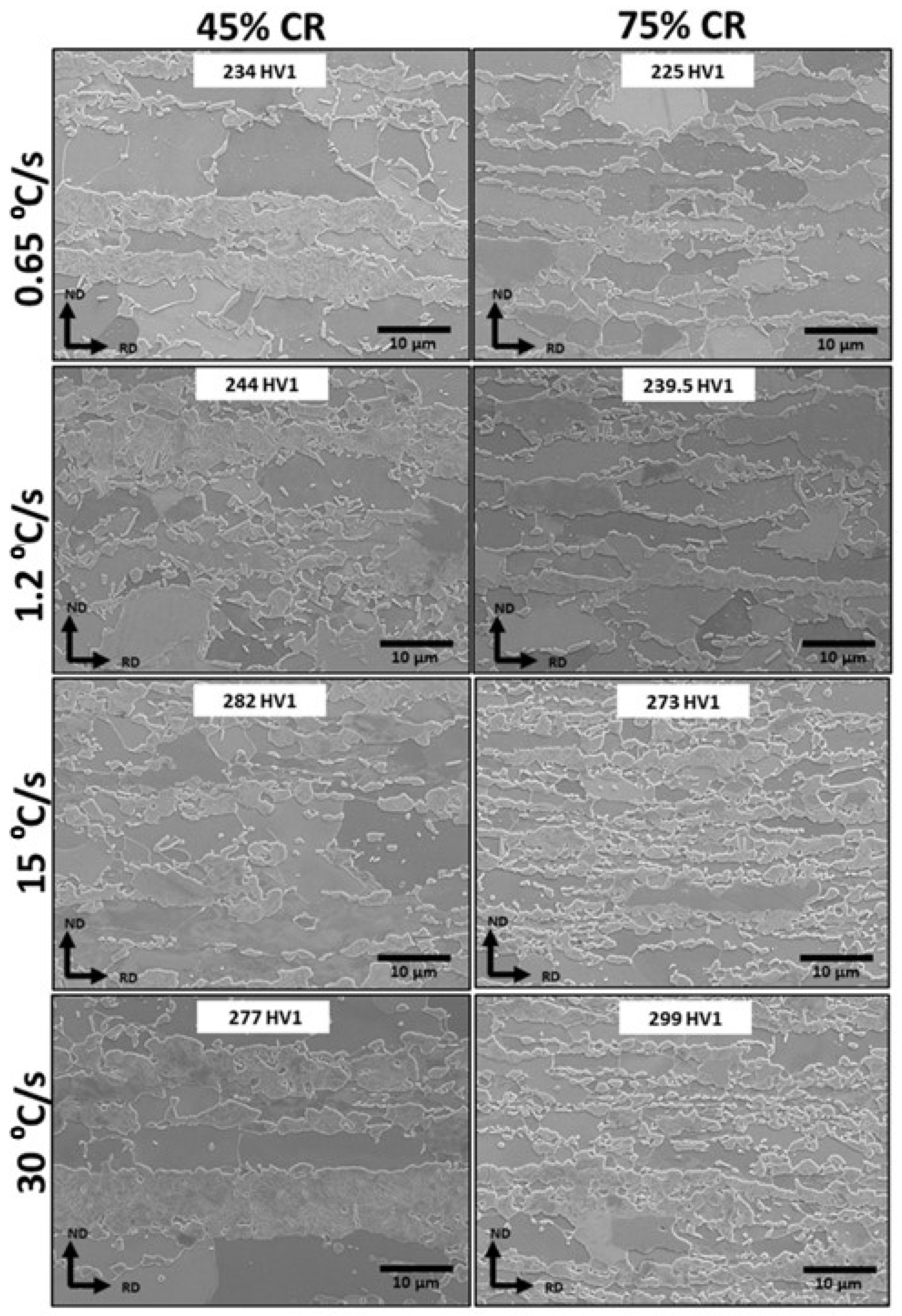
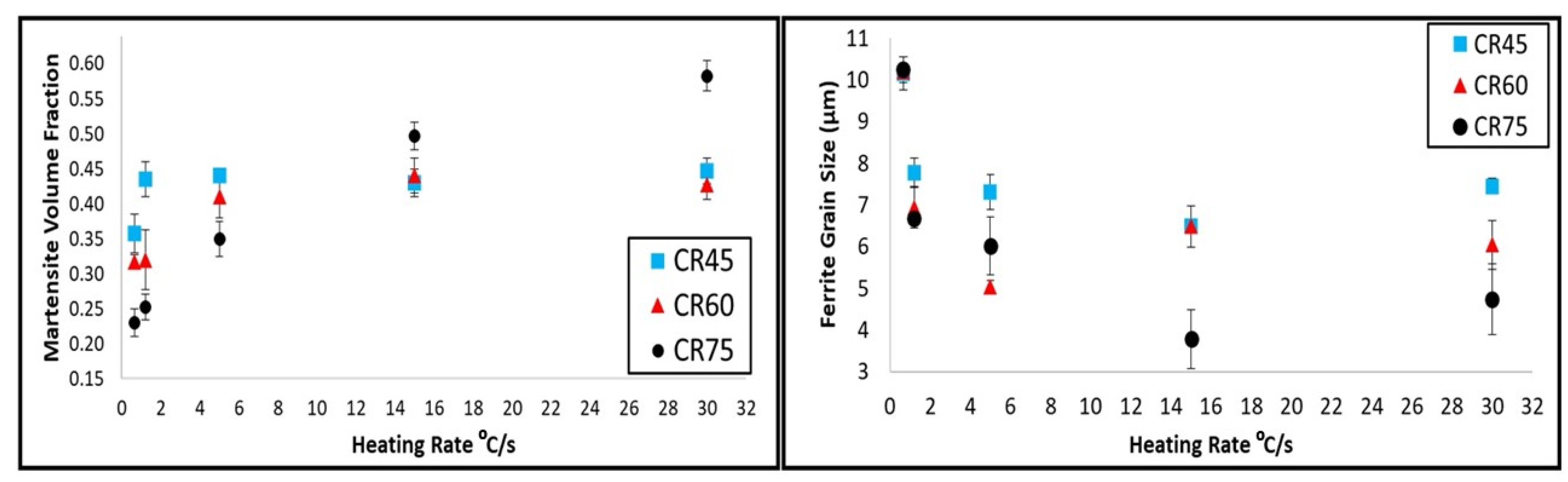
  • Variant 1 looked at the influence of the heating rate and cold rolling reduction on the morphology and volume fraction of martensite after inter-critical annealing. It was found that the presence of a higher amount of dislocations and fragmented cementite particles from a higher cold rolling reduction caused an increase in martensite volume fraction for the higher heating rate samples.
  • From the test matrix for the Variant 1 work (heating rates from 0.65 to 30 °C/s and cold reductions of 45, 60 and 75%), a cold reduction of 75%, and the heating rate of 15 °C/s produced an optimum combination of fine ferrite grain size (3.8 μm) and high martensite volume fraction (50%) and therefore has the potential to give a good combination of strength and ductility.
  • Variant 2 considered differences in the initial hot rolled microstructure to give a more uniform carbon distribution compared to that of the standard ferrite/pearlite microstructures. Both ferrite–50% bainite and fully martensite/bainite initial hot rolled microstructures produced desirable annealed DP steel microstructures with fine ferrite grain size and martensite with necklace morphology for all cold rolling reductions.
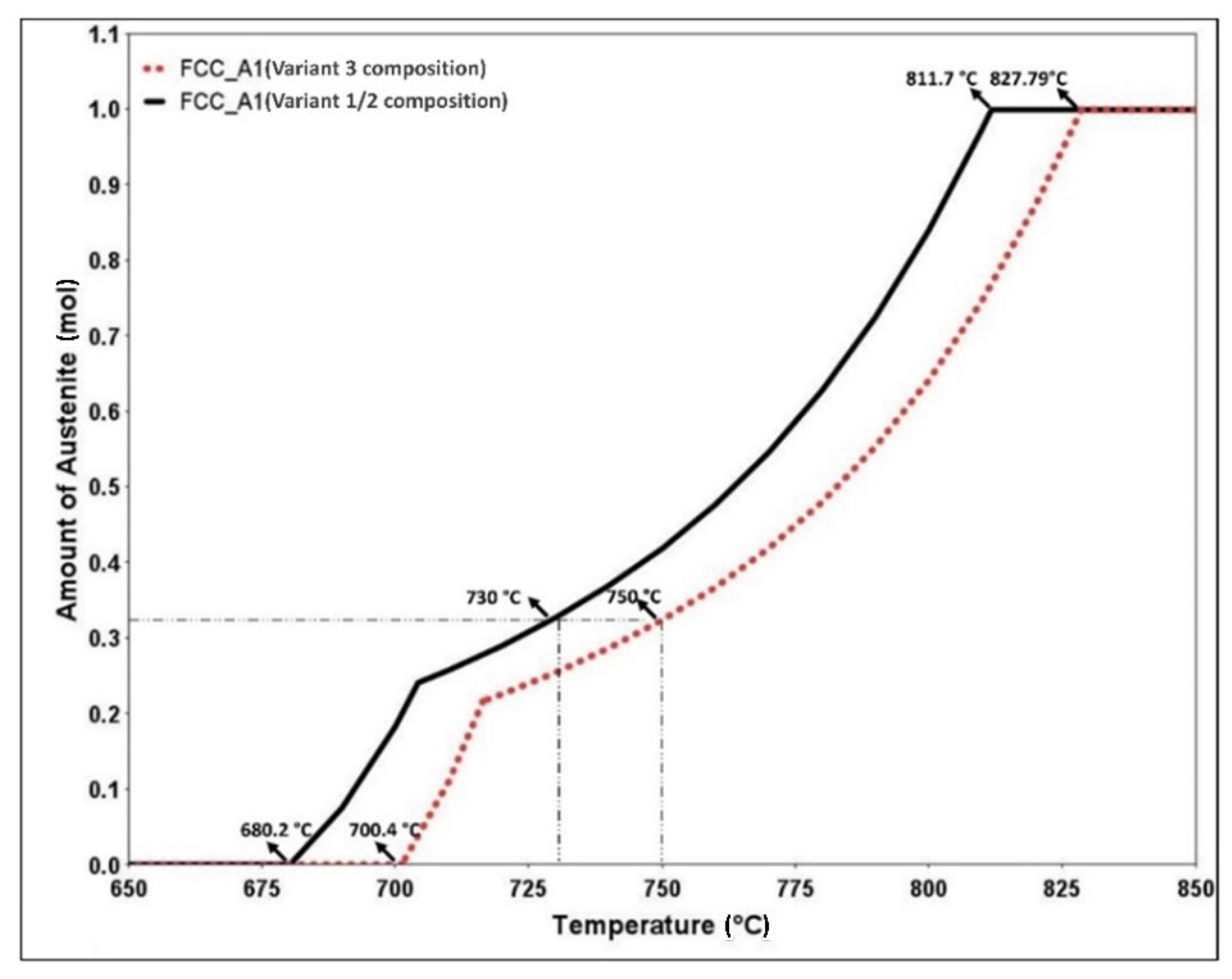
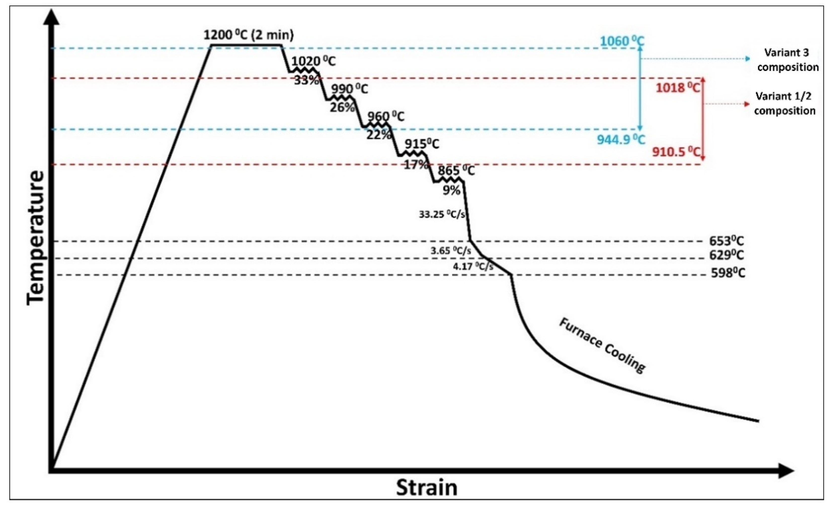
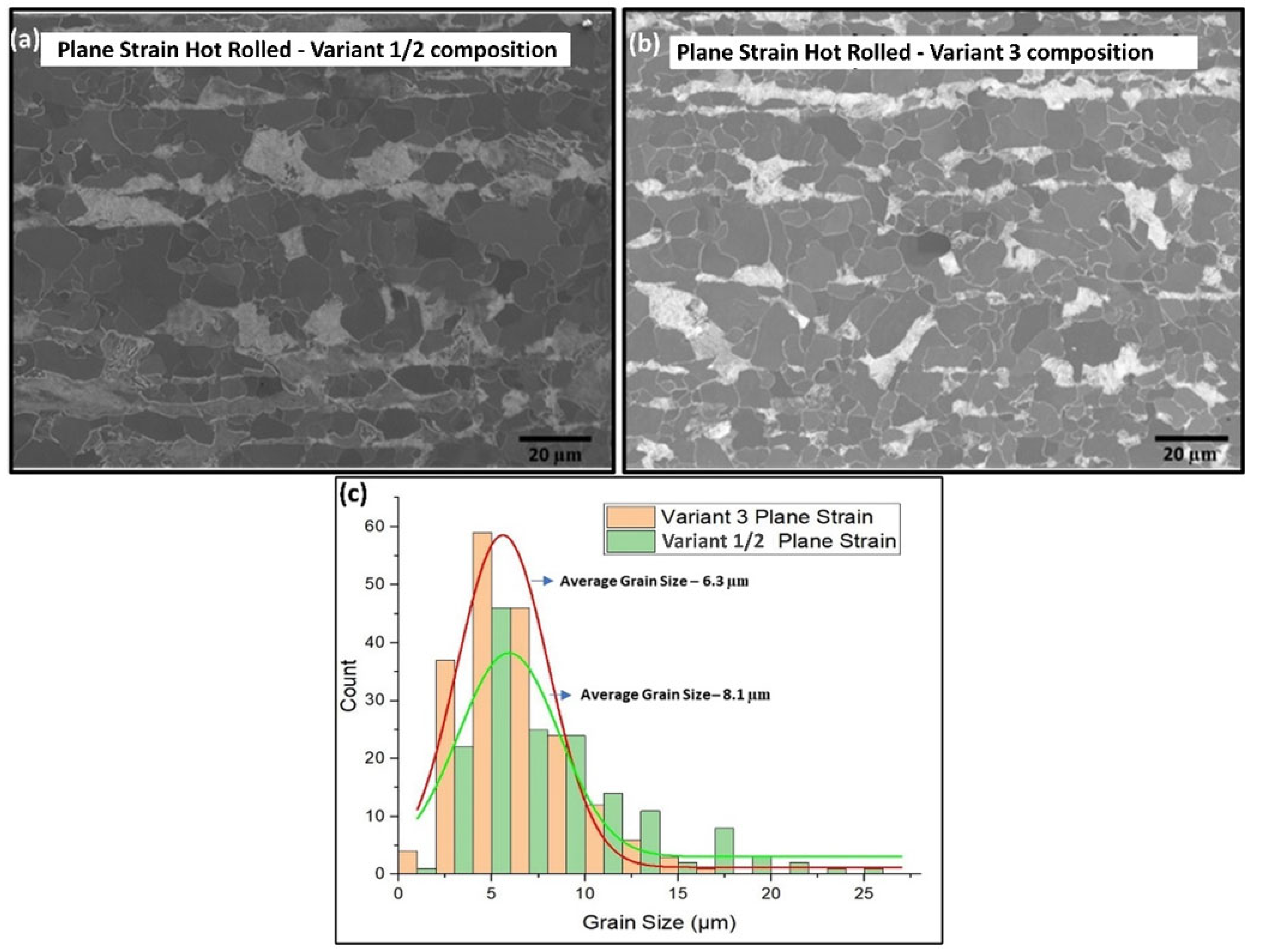
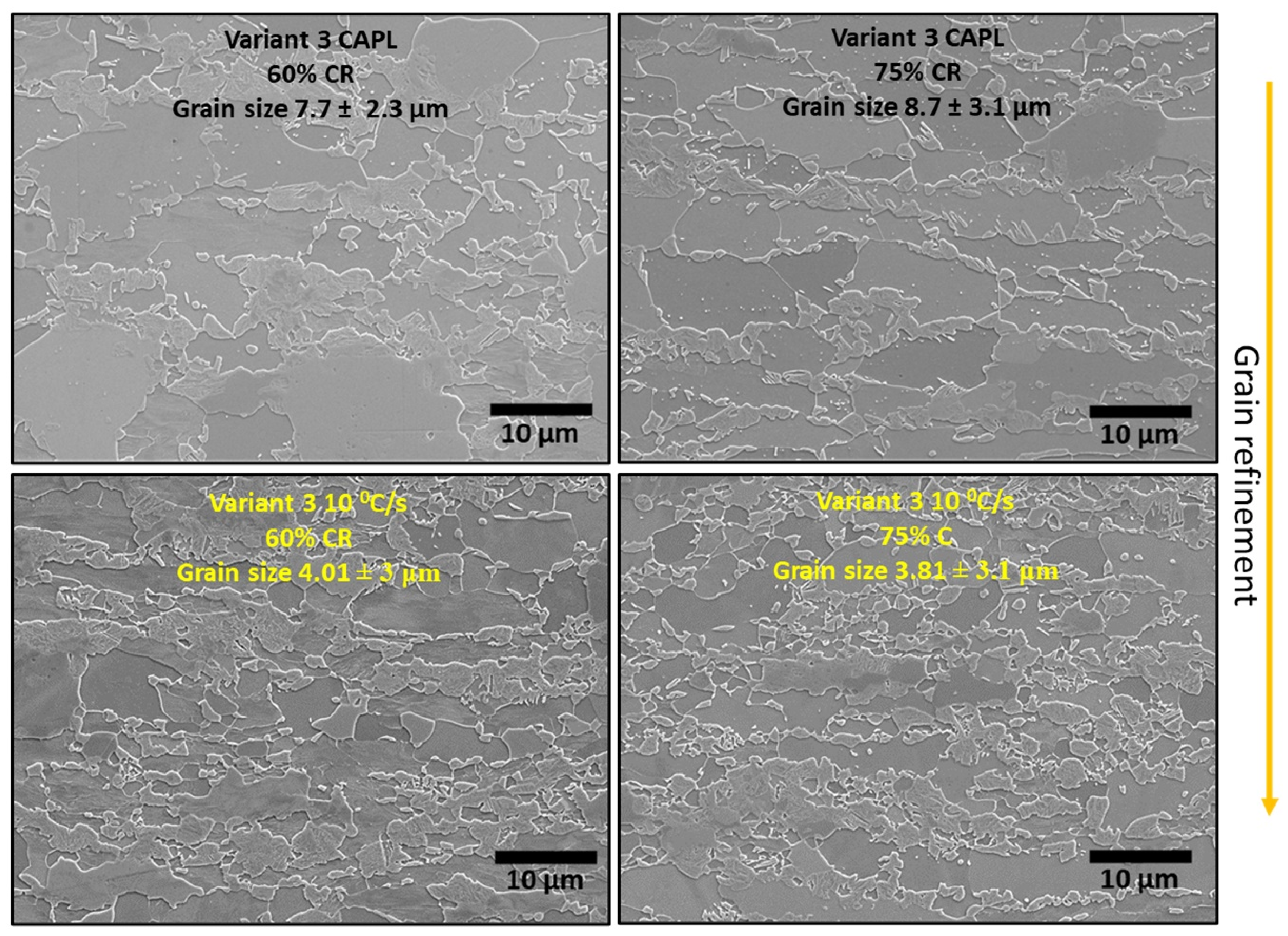
  • The Variant 3 study used a lower Mn content and higher Nb content composition, compared to the Variant 1/2 composition to generate a hot rolled microstructure with a smaller ferrite grain size but the same hardness (balanced grain size and solid solution strengthening). It was found that the increase in niobium content increased the TNR temperature and consequently decreased the ferrite grain in the hot rolled material (6.3 µm) when compared to that of the Variant 1/2 composition (8.1 µm). However, after inter-critical annealing/quenching ferrite grain refinement in Variant 3 steel was achieved only for the 45% cold reduction sample, whereas both the 60% and 75% cold reduction Variant 3 samples produced a higher ferrite grain size due to rapid recrystallisation leading to greater grain growth.
  • A higher heating rate of 10 °C/s was required to produce grain refinement in the 60% and 75% cold-reduced Variant 3 samples.
This work forms the precursor to further studies looking at influence of slow and fast cooling, as well as over ageing in continuous annealing of DP grades.

Author Contributions

Conceptualization, B.B., C.S. and C.D.; methodology, B.B, C.S. and C.D.; validation, B.B., C.S., D.F. and C.D.; formal analysis, B.B. and C.S.; investigation, B.B.; resources, C.S., D.F. and C.D.; data curation, B.B.; writing—original draft preparation, B.B.; writing—review and editing, B.B., C.S., D.F. and C.D.; visualization, B.B., C.S. and C.D.; supervision, D.F. and C.D.; project administration, D.F. and C.D.; funding acquisition, D.F. and C.D. All authors have read and agreed to the published version of the manuscript.

Funding

The authors gratefully acknowledge the funding for the work from EPSRC under the Prosperity Partnership (EP/S005218/1).

Institutional Review Board Statement

Not applicable.

Informed Consent Statement

Not applicable.

Data Availability Statement

Not applicable.

Conflicts of Interest

The authors declare no conflict of interest.

References

  1. Huang, J.; Poole, W.J.; Militzer, M. Austenite formation during intercritical annealing. Metall. Mater. Trans. A 2004, 35, 3363–3375. [Google Scholar] [CrossRef]
  2. Azizi-Alizamini, H.; Militzer, M.; Poole, W.J. Formation of Ultrafine Grained Dual Phase Steels through Rapid Heating. ISIJ Int. 2011, 51, 958–964. [Google Scholar] [CrossRef] [Green Version]
  3. Scott, C.; Fazeli, F.; Amirkhiz, B.S.; Pushkareva, I.; Allain, S. Structure-properties relationship of ultra-fine grained V-microalloyed dual phase steels. Mater. Sci. Eng. A 2017, 703, 293–303. [Google Scholar] [CrossRef]
  4. Anbarlooie, B.; Kadkhodapour, J.; Toudeshky, H.H.; Schmauder, S. Micromechanics of dual-phase steels: Deformation, damage, and fatigue. In Handbook of Mechanics of Materials; Springer: Berlin/Heidelberg, Germany, 2019; pp. 1127–1156. [Google Scholar] [CrossRef]
  5. Tasan, C.; Hoefnagels, J.; Diehl, M.; Yan, D.; Roters, F.; Raabe, D. Strain localization and damage in dual phase steels investigated by coupled in-situ deformation experiments and crystal plasticity simulations. Int. J. Plast. 2014, 63, 198–210. [Google Scholar] [CrossRef] [Green Version]
  6. Ismail, K.; Perlade, A.; Jacques, P.J.; Pardoen, T.; Brassart, L. Impact of second phase morphology and orientation on the plastic behavior of dual-phase steels. Int. J. Plast. 2019, 118, 130–146. [Google Scholar] [CrossRef]
  7. Chbihi, A.; Barbier, D.; Germain, L.; Hazotte, A.; Gouné, M. Interactions between ferrite recrystallization and austenite formation in high-strength steels. J. Mater. Sci. 2014, 49, 3608–3621. [Google Scholar] [CrossRef]
  8. Azizi-Alizamini, H.; Militzer, M.; Poole, W.J. Austenite formation in plain low-carbon steels. Metall. Mater. Trans. A 2011, 42, 1544–1557. [Google Scholar] [CrossRef]
  9. Lolla, T.; Cola, G.; Narayanan, B.; Alexandrov, B.; Babu, S. Development of rapid heating and cooling (flash processing) process to produce advanced high strength steel microstructures. Mater. Sci. Technol. 2011, 27, 863–875. [Google Scholar] [CrossRef]
  10. Zheng, C.; Raabe, D. Interaction between recrystallization and phase transformation during intercritical annealing in a cold-rolled dual-phase steel: A cellular automaton model. Acta Mater. 2013, 61, 5504–5517. [Google Scholar] [CrossRef]
  11. Li, P.; Li, J.; Meng, Q.; Hu, W.; Xu, D. Effect of heating rate on ferrite recrystallization and austenite formation of cold-roll dual phase steel. J. Alloys Compd. 2013, 578, 320–327. [Google Scholar] [CrossRef]
  12. Mohanty, R.R.; Girina, O.A.; Fonstein, N.M. Fonstein, Effect of heating rate on the austenite formation in low-carbon high-strength steels annealed in the intercritical region. Metall. Mater. Trans. A 2011, 42, 3680–3690. [Google Scholar] [CrossRef]
  13. Teixeira, J.; Moreno, M.; Allain, S.; Oberbillig, C.; Geandier, G.; Bonnet, F. Intercritical annealing of cold-rolled ferrite-pearlite steel: Microstructure evolutions and phase transformation kinetics. Acta Mater. 2021, 212, 16920. [Google Scholar] [CrossRef]
  14. Kulakov, M.; Poole, W.J.; Militzer, M. The effect of the initial microstructure on recrystallization and austenite formation in a DP600 Steel. Metall. Mater. Trans. A 2013, 44, 3564–3576. [Google Scholar] [CrossRef]
  15. Abad, R.; Fernández, A.I.; Lopez, B.; Rodriguez-Ibabe, J.M. Interaction between recrystallization and precipitation during multipass rolling in a low carbon niobium microalloyed steel. ISIJ Int. 2001, 41, 1373–1382. [Google Scholar] [CrossRef] [Green Version]
  16. Zhu, Y.; Slater, C.; Connolly, S.; Farrugia, D.; Davis, C. Rapid alloy prototyping for strip steel development: DP800 steel case study. Ironmak. Steelmak. 2021, 48, 493–504. [Google Scholar] [CrossRef]
  17. Tasan, C.; Diehl, M.; Yan, D.; Bechtold, M.; Roters, F.; Schemmann, L.; Zheng, C.; Peranio, N.; Ponge, D.; Koyama, M.; et al. An Overview of Dual-Phase Steels: Advances in Microstructure-Oriented Processing and Micromechanically Guided Design. Annu. Rev. Mater. Sci. 2015, 45, 391–431. [Google Scholar] [CrossRef]
  18. ASTM Standard, E112-12; Standard Test Methods for Determining Average Grain Size, ASTM Int. E112-12. ASTM: West Conshohocken, PA, USA, 2012.
  19. ASTM E562-19e1; Standard Test Method for Determining Volume Fraction by Systematic Manual Point Count, Practice. ASTM: West Conshohocken, PA, USA, 2011.
  20. Yang, D.Z.; Brown, E.L.; Matlock, D.K.; Krauss, G. Ferrite recrystallization and austenite formation in cold-rolled intercritically annealed steel. Metall. Trans. A 1985, 16, 1385–1392. [Google Scholar] [CrossRef]
  21. Granbom, Y. Structure and Mechanical Properties of Dual Phase Steels—An Experimental and Theoretical Analysis. Ph.D. Thesis, KHT School of Industrial Engineering and Management (ITM), Materials Science and Engineering, Mechanical Metallurgy, Stockholm, Sweden, 2010. [Google Scholar]
  22. Law, N.C.; Edmonds, D.V. The formation of austenite in a low-alloy steel. Metall. Mater. Trans. A 1980, 11, 33–46. [Google Scholar] [CrossRef]
  23. Mohanty, R.; Girina, O. Effect of Coiling Temperature on Kinetics of Austenite Formation in Cold Rolled Advanced High Strength Steels. Mater. Sci. Forum 2012, 706–709, 2112–2117. [Google Scholar] [CrossRef]
  24. Bai, D.Q.; Yue, S.; Sun, W.P.; Jonas, J.J. Effect of Deformation Parameters on the No-Recrystallization Temperature in Nb-Bearing Steels. Metall. Mater. Trans. A 1993, 24, 2151–2159. [Google Scholar] [CrossRef]
  25. Barbosa, R.; Boratto, F.; Yue, S.S.; Jonas, J.J. The influence of chemical composition on the recrystallisation behaviour of microalloyed steels. In Proceedings of the International Conference on Processing, Microstructure and Properties of HSLA Steels, Pittsburgh, PA, USA, 1 September 1988; pp. 51–61. [Google Scholar]
  26. Homsher, C.N.; Van Tyne, C.J. Determination of No-Recrystallization Temperature (Tnr) in Multiple Microalloyed Steels. Master’s Thesis, Colorado School of Mines, Golden, CO, USA, 2012. [Google Scholar]
  27. Popova, N.; Dement, T.; Nikonenko, E.; Kurzina, I.; Kozlov, E. Structure and phase composition of manganese steels modified by alloying elements. AIP Conf. Proc. 2017, 1800, 030001. [Google Scholar] [CrossRef] [Green Version]
  28. Calcagnotto, M.; Ponge, D.; Raabe, D. On the effect of manganese on grain size stability and hardenability in ultrafine-grained ferrite/martensite dual-phase steels. Metall. Mater. Trans. A 2012, 43, 37–46. [Google Scholar] [CrossRef]
Figure 1. CCT curve obtained from JMatPro for Variant 2, the assumed prior austenite grain size 25 mm.
Metals 12 01158 g001
Figure 2. Plane strain hot deformation time/temperature/strain profile for the Variant 3 testing.
Metals 12 01158 g002
Figure 3. (a) Optical micrograph of hot rolled Variant 1 steel. (bd) SEM micrograph of cold rolled 45%, 60% and 75% Variant 1 samples.
Metals 12 01158 g003
Figure 4. SEM microstructural images and the corresponding hardness values for 45% and 75% Variant 1 cold-reduced samples annealed at heating rates of 0.65 °C/s, 1.2 °C/s (CAPL), 15 °C/s and 30 °C/s, respectively.
Metals 12 01158 g004
Figure 5. Effect of the heating rate on the martensite volume fraction and ferrite grain size for all the cold reductions in Variant 1.
Metals 12 01158 g005
Figure 6. SEM micrographs of hot rolled and simulated coiled (Gleeble) samples with microstructures of (a) ferrite–20% pearlite, (b) ferrite–50% bainite and (c) fully martensite/bainite, respectively, in Variant 2.
Metals 12 01158 g006
Figure 7. SEM micrographs of the cold rolled 45%, 60% and 75% samples for ferrite–50% bainite and fully martensite/bainite microstructures in Variant 2.
Metals 12 01158 g007
Figure 8. SEM micrographs of cold rolled Ferrite–Pearlite (FP), Ferrite–50% Bainite (FB) and fully Martensite/Bainite (M) steel samples annealed using a peak temperature of 730 °C (FP and FB) and 750 °C (M), respectively.
Metals 12 01158 g008
Figure 9. Comparison of the equilibrium austenite fractions for Variant 1/2 composition and Variant 3 composition predicted by ThermoCalc.
Metals 12 01158 g009
Figure 10. Temperature–strain profile used for plane strain rolling in the Gleeble HDS-V40 for the Variant 1/2 composition and Variant 3 composition steels with their corresponding TNR temperature range.
Metals 12 01158 g010
Figure 11. SEM microstructure for plane strain Gleeble HDS-V40 hot deformed: (a) Variant 1/2 composition steel and (b) Variant 3 steel and (c) corresponding grain size distributions.
Metals 12 01158 g011
Figure 12. SEM micrographs of the cold rolled 45%, 60% and 75% samples for the Variant 1/2 composition and Variant 3 composition steels.
Metals 12 01158 g012
Figure 13. SEM microstructures of cold rolled 45% (a) Variant 1/2 composition and (b) Variant 3 composition steels inter-critically annealed using the standard CAPL heating rate to peak temperatures of 730 °C and 750 °C, respectively.
Metals 12 01158 g013
Figure 14. SEM microstructures of the cold rolled 60% and 75% Variant 3 samples inter-critically annealed using a heating rate of 1.2 °C/s and a higher heating rate of 10 °C/s.
Metals 12 01158 g014
Table 1. Chemical composition (wt%) of the DP 800 steel used for the Variant 1 and Variant 3 study.
AlloyFeCMnSiCr + MoNb
Variant 197.20.141.770.290.5–1.00.03
Variant 397.70.141.30.260.5–1.00.048
Table 2. Cooling rates and the corresponding microstructures obtained from the Variant 2 Gleeble tests.
Cooling MethodCooling Rate (°C/s)Microstructure Obtained
As Received-Ferrite–20% Pearlite
Forced Air Quench−14.0250% Ferrite–50% Bainite
Water Quench−190.2100% Martensite
Table 3. Comparison of the ferrite grain sizes and martensite volume fractions with respect to cold reductions and initial microstructures after inter-critical annealing.
Initial
Microstructure
Cold Reduction %
45%60%75%
Grain Size (µm)VFGrain Size (µm)VFGrain Size (µm)VF
FP8.2297.8226.426
FB5.7314.2362.5933
M5.1333.9322.9736
Table 4. Comparison of the Ae1, Ae3, Ms and TNR temperatures for the variant 1/2 composition and Variant 3 composition.
DP800
Alloy
Ae1 (°C)Ae3 (°C)Ms (°C)TNR Temperature (°C)TNR–Ae3 (°C)
Barbosa et al.Bai et al.Fletcher et al.Barbosa et al.Bai et al.Fletcher et al.
Variant 1/2 composition680.2811.7432.0946.81018.9910.5135.1207.298.8
Variant 3 composition 700.4827.9448.51036.51060.3944.9208.6232.4117.0
Table 5. Comparison of the hardness values, ferrite grain sizes and martensite volume fractions with respect to cold reductions for the Variant 1/2 composition and Variant 3 composition samples annealed using the standard CAPL heating rate.
VariantCold Reduction %
456075
HV2Grain Size (µm)VFHV2Grain Size (µm)VFHV2Grain Size (µm)VF
Variant 1/2 composition (730 °C)2458.10.372196.40.372045.90.33
Variant 3 composition (750 °C)2647.00.412387.70.422108.70.35
Publisher’s Note: MDPI stays neutral with regard to jurisdictional claims in published maps and institutional affiliations.

