Article

Development of Ultrafine–Grained and Nanostructured Bioinert Alloys Based on Titanium, Zirconium and Niobium and Their Microstructure, Mechanical and Biological Properties

1
Institute of Strength Physics and Materials Science of Siberian Branch Russian Academy of Sciences, 634055 Tomsk, Russia
2
Research School of Physics, School of Advanced Manufacturing Technologies, National Research Tomsk Polytechnic University, 634050 Tomsk, Russia
3
Physics Technical Faculty, Tomsk Materials Research Multiple Access Center, National Research Tomsk State University, 634050 Tomsk, Russia
4
Inorganic Chemistry and Center for Nanointegration Duisburg-Essen (CeNIDE), University of Duisburg-Essen, 45141 Essen, Germany
5
General Research Institute for Nonferrous Metals, Beijing 100088, China
*
Author to whom correspondence should be addressed.
Metals 2022, 12(7), 1136; https://doi.org/10.3390/met12071136
Submission received: 12 May 2022 / Revised: 24 June 2022 / Accepted: 28 June 2022 / Published: 2 July 2022
(This article belongs to the Special Issue Thermomechanical Treatment of Metals and Alloys)

Abstract

:
For this paper, studies of the microstructure as well as the mechanical and biological properties of bioinert titanium, zirconium, and niobium alloys in their nanostructured (NS) and ultrafine-grained (UFG) states have been completed. The NS and UFG states were formed by a combined two-step method of severe plastic deformation (SPD), first with multidirectional forging (MDF) or pressing into a symmetrical channel (PSC) at a given temperature regime, and then subsequent multi-pass groove rolling (MPGR) at room temperature, with pre-recrystallization annealing. Annealing increased the plasticity of the alloys in the NS and UFG states without changing the grain size. The UFG structure, with an average size of structural elements of no more than 0.3 μm, was formed as a result of applying two-step SPD and annealing. This structure presented significant improvement in the mechanical characteristics of the alloys, in comparison with the alloys in the coarse-grained (CG) or small-grained (SG) states. At the same time, although the formation of the UFG structure leads to a significant increase in the yield strength and tensile strength of the alloys, their elastic modulus did not change. In terms of biocompatibility, the cultivation of MG-63 osteosarcoma cells on the polished and sandblasted substrates demonstrated high cell viability after 10 days and good cell adhesion to the surface.

1. Introduction

During the last few decades, the scientific field associated with the production of biocompatible materials has seen intensive growth. More advanced medical technologies, materials, and items are being developed, including implants that could replace injured and disabled areas of bone tissue [1,2,3,4,5]. The functional reliability of these materials depends on such factors as their biochemical, cellular, tissue, and biomechanical compatibility. This, in turn, imposes strict requirements on implant materials [1,6,7,8].
The materials intended for producing implants should not only be harmless and biocompatible with the human organism but must also have the necessary strength and plasticity [3]. Depending on the implantation site and the implant’s purpose, new requirements are constantly being specified. In particular, these materials should possess optimal mechanical properties (yield strength, ultimate strength, hardness, fatigue limit, wear resistance, cyclic fatigue, etc.) and must be able to integrate into the bone tissue, which in turn principally influences the material’s elastic modulus [9,10,11,12]. Low elastic modulus leads to the uniform distribution of deformation strains and stresses at the bone–implant interfaces and prevents possible fractures at the rigid fixation of the implant to the bone and bone resorption in those areas without mechanical stress [1].
Currently, a wide range of implant materials is used in clinical practice: metals and metal alloys, ceramics, polymers, and composite materials [1,2,3,8,9,10,11,12,13,14,15]. However, the majority of biocompatible materials do not possess all the required biological and mechanical properties. This explains a number of ineffective results after implantation, including implant rejection [6,7], and stimulates continuous research and the development of advanced materials that can be used in medicine.
Most manufactured implants include valvular bioinert metals (titanium, zirconium, niobium, hafnium, and tantalum) and their alloys [3,16]. The main advantages of these materials are their high corrosion resistance and good biocompatibility, non-toxicity, low thermal linear expansion and thermal conductivity, non-magnetization, and low density. The most widely used alloys in medicine are commercially pure titanium and titanium alloys of medium strength, such as Ti-6Al-7Nb and Ti-6Al-2.5Fe [16,17,18,19]. However, the preferred alloys are those without any toxic alloying elements, such as Al, V, or Mo, which could affect the organism [20,21]. In this regard, the most promising elements are niobium and zirconium. Since Ti and Nb are non-toxic elements, the Ti-Nb binary alloys exhibit excellent biocompatibility. In particular, the Ti-40Nb and Ti-45Nb alloys demonstrate a good combination of Young’s (elasticity) modulus, corrosion resistance, and biocompatibility [22,23,24,25]. The elasticity modulus of titanium and medium-strength titanium alloys is in the range of 100–120 GPa, thus significantly exceeding Young’s modulus of the bone tissue. The 40 wt % of Nb in the Ti alloy leads to the stabilization of the β-phase and the reduction of Young’s modulus to 55–60 GPa, which is comparable to Young’s modulus of cortical bone (10–50 GPa) [18,19,20].
Zirconium alloys, Zr-1Nb or Zr-2.5Nb, have high corrosion resistance in a biological environment, high fatigue strength, and low Young’s modulus, which in itself makes them potentially productive for use as commercial implants [26,27,28,29].
Poor strength characteristics hinder the use of commercially pure titanium and Ti-40Nb, Ti-45Nb, and Zr-1Nb alloys [3]. One of the ways to solve this problem is by the use of several types of thermo-mechanical and deformation processing, in particular, severe plastic deformation (SPD) [30]. With SPD, nanostructured (NS) or ultrafine-grained (UFG) states are formed in the metal material structure, resulting in an improvement in their mechanical properties [31,32,33].
Currently, the question of how to form UFG and NS states in bio-medical metal materials by SPD is being addressed by a number of research groups. These states can be achieved using the following methods: equal channel angular pressing and its modifications (ECAP) [34,35,36,37,38,39,40,41,42], high-pressure torsion [43,44,45], multidirectional forging (MDF) [46,47,48,49], and cyclic extrusion and compression (CEC) [49,50,51], as well as various methods of severe plastic deformation and rolling [52,53,54,55,56,57] and combined methods [58,59,60,61,62,63,64,65]. These methods can be used for the formation of UFG and NS structures in commercially pure titanium [36,37,38,39,50,51,65,66], in Ti–Nb alloy systems [67,68,69,70,71,72,73], and in Zr–Nb systems [74,75,76,77,78,79,80,81,82,83].
However, the list of such diverse SPD methods is incomplete and requires more advanced methods, as well as further research and development. Today, the bioinert Zr-Nb and Ti-Nb alloy systems are actively used in medicine, and numerous issues related to their applications are still open, thus requiring further research in this field.
The present paper focuses on the microstructure, mechanical, and biological properties of UFG and NS bioinert alloys for biomedical applications (commercially pure titanium, zirconium Zr-1 wt % Nb alloy, and titanium–niobium Ti-45 wt % Nb alloy) by combined SPD methods, including MDF or pressing into a symmetric channel (PSC) (see Patent RF, 2315117 and Patent RF, 2418092) and subsequent multi-pass groove rolling (MPGR). Moreover, the medical application of dental implants made of UFG titanium is considered.

2. Materials and Research Methods

2.1. Materials

In this paper, we describe the results obtained for numerous alloys used in medicine: commercially pure VT1-0 titanium (VSMPO-AVISMA, Verkhnaya Salda, Russia), zirconium—1 wt % niobium (Zr-1Nb) alloy (SC “Chepetsky Mechanical Plant”, Glazov, Russia), and titanium—45 wt % niobium (Ti-45Nb) alloy (GRINM, Beijing, China; SC “Chepetsky Mechanical Plant”, Glazov, Russia). Rods made of commercially pure titanium grade VT1-0 (wt %), comprising Ti 99.49, Si 0.10, Fe 0.25, O 0.20, H 0.01, and N 0.04, were used in their initial state. The Zr-1Nb alloy rods, comprising (wt %) Zr 96.54, Nb 1.01, Mo ≤ 0.32, W ≤ 0.10, Fe ≤ 0.29, and Ti ≤ 0.88, were used in their initial state, then treated with vacuum annealing at 580 °C for 3 h [84]. The Ti alloy, comprising (wt %) Ti 55.32, Nb 44.67, Cr ≤ 0.10, Fe ≤ 0.05, C ≤ 0.05, and W ≤ 0.13, was produced via electro-arc multistep melting and subsequent quenching at 1100 °C in water (GRINM, Beijing, China) [85]. After quenching, the rod surface was mechanically cleaned from the oxide contamination.

2.2. Technological Aspects of Combined SPD, including MDF or PSC and Subsequent MPGR

As described above, bulk NS and UFG states in metals and alloys are produced using different SPD methods [30]. It is well-known that if structural heterogeneity is caused by one type of severe deformation, it can be eliminated by another type of deformation. Thus, the elimination of structural anisotropy and mechanical properties in a material can be achieved with the combined SPD methods. In the first stage, equal channel angular pressing (ECAP) is used as one of the SPD methods, whereas in the second stage, the methods are cold and/or hot rolling, drawing or extrusion [58,59,60,61,62,63,64].
Multidirectional forging (MDF) is one of the few SPD methods that include multiple changes of direction of the deformation axis, i.e., “abc” deformation [46,47]. Changing the axis of the applied deforming stress allows a large total value of deformation after each forging pass to be achieved, which, in turn, significantly improves the structural homogeneity in the billet’s cross-sectional area. This method makes it possible to produce a UFG structure in rather brittle materials since the treatment begins at a high temperature. Thus, this method exerts a negligible load on the instrument. For example, the selection of the appropriate temperature-deformation conditions provides a possible UFG structure in pure titanium [86]. In addition, this method is less time-consuming than other ECAP methods, and, at the same time, does not require special equipment [30].
Since pressing into a symmetric channel (PSC) is a more efficient method of grain refining, this can be used instead of the MDF method (see Patent RF, 2315117 and Patent RF, 2418092). In this case, the alloy billet is pressed into the shape of a parallelepiped under loading from the vertical press-mold channel into two symmetrically located horizontal channels. As a result, since all the channels have the same cross-section, a new parallelepiped billet of the same size is formed.
Neither MDF nor PSC achieves good homogeneity in the billet volume. The authors of [87] have demonstrated that PSC produces a UFG structure in titanium. However, the microstructure is heterogeneous in the billet volume. The structural element size in the central part of the billet is within 0.09–0.15 µm; however, increasing the distance from the center to the billet periphery means that the size range of these structural elements increases to 0.2–0.3 µm. Simultaneously, the heterogeneity of micro-hardness distribution over the material volume is not eliminated.
To effectively improve the strength properties of the billet and to achieve homogeneous mechanical properties in the billet volume, subsequent deformation MPGR is applied [59,87].
The two combined SPD methods i.e., MDF or PSC and subsequent rolling, are described below. Figure 1 illustrates the MDF process and the subsequent MPGR.
The first stage of billet deformation includes free-forging in several cycles at a rate of 103–101 s−1, with sequential multistep temperature decrease within the range of (0.3–0.6)⋅Tm, where Tm is the melting temperature of the material [89]. This promotes the plastic deformation of refractory metals at a given stress. Each cycle includes three-fold forging passes at a certain temperature. Through successive forging passes, the temperature of the billet gradually decreases to 50 °C. For example, in the case of MDF with titanium, the deformation temperature decreases from 500 to 400 °C [90].
After each forging pass, the billet is rotated by 90° around the roll axis to transform the deformation axis. This improves the dead zones in the material after the previous pass and leads to a continuous homogeneous structure. The value of the relative deformation of the sample at each pressing stage was 0.71–0.74. This is due to the fact that lower degrees of deformation do not provide sufficient conditions for the development of dynamic recrystallization processes, and deformations to higher degrees can lead to the billet’s destruction.
The total strain value e is calculated as the sum of the true strain values under the conditions of each billet compression (upsetting). The true strain value was determined as the natural logarithm of the ratio of the initial to the final sample thickness at each step of the sample upsetting:
e = i = 1 n l n h 0 i h i
where h0i is the initial billet height, hi is the final billet height, and i is the upsetting cycle number.
The true logarithmic strain value was calculated using the following formula:
e = l n h k h 0 .
In the second stage, the samples were deformed using the MPGR method in grooved or flat rollers at room temperature. Rolling was carried out repeatedly since the shrinkage at each pass of the billet through the roller was not more than 0.02. The true logarithmic strain value e during rolling reached 2.1. The true deformation at this stage was determined by Equation (2).
Despite the fact that MDF minimizes the labor intensity of the technological process, to improve grain refinement in alloys in the initial deformation cycles, higher applied stresses and confined deformation conditions are required. In this case, PSC provides such conditions. The scheme of the second combined SPD method is shown in Figure 2.
The first stage involves the pressing-through of the billet into the press-mold, with changing shrinking axis–from the vertical channel into two symmetric horizontal channels. A specially designed press-mold with the channels having the same section is used to maintain the initial billet form for the next pressing cycle. PSC improves the stress conditions, increases deformation uniformity, and reduces the tensile stress, which can lead to the formation of lateral cracks under conditions of billet upsetting. The billet is rotated around its long axis by 90° to change its position for the next pressing cycle.
PSC can be carried out at temperatures lower than those needed for MDF. Technologically, this is due to two main points: the possible danger of mechanical destruction of the material, caused by the press-mold, and premature wear of the material at high temperatures. The PSC process for titanium is carried out at a reduction of temperature from 500 to 400 °C, which, in turn, initiates limited deformation conditions and results in more efficient grain refinement with fewer cycles [90].
The second stage of deformation includes the use of MPGR under the same conditions as those after MDF. After rolling, the heterogeneity of the structure decreases and provides additional deformation strengthening. However, in this case, the stress increases and the plasticity decreases.
An increase in plasticity and a decrease in internal stresses in the alloys after combined SPD can be achieved by recovery annealing in a particular temperature range that ensures the formation of the alloy structure with stable mechanical properties, without excessive working softening of the material. Thus, the microhardness thermal resistance zone in UFG titanium corresponds to a temperature range of 250–300 °C in a time interval of 1–3 h (Figure 3) [87]. At temperatures above 300 °C, a visible decrease in mechanical properties is observed, due to active grain growth during the recrystallization of the UFG structure. In this case, the annealing temperature after MDF or PCP in the case of MPGR titanium should be 300 °C.
After MDF or PSC with MPGR, rod-like billets with a 6 mm × 6 mm2 square section and a length of 400–1000 mm were produced.

2.3. Research Methods

After SPD, the microstructure and phase composition of the samples were investigated by optical microscopy AXIOVERT-200MAT (Carl Zeiss, Industrielle Messtechnik GmbH Oberkochen, Germany), transmission electron microscopy (TEM) (including JEOL JEM 2100 and JEOL JEM 2010, JEOL Ltd., Akishima, Tokyo, Japan), and X-ray diffraction analysis using CuKα radiation (Bruker D8 Advance, Karlsruhe, Germany, λ = 1.54 Å). The measurements were carried out in the 2θ range of 10–90°, with a scan step of 0.01° and an acquisition time of 1 s. The phase was identified using the cards from the database of the International Center for Diffraction Data (ICDD) PDF4+. Microhardness was measured according to the Vickers test on a Duramin-5 microhardness tester (Struers, Ballerup, Denmark).
Mechanical properties were ascertained using an Instron tension testing machine (Instron European Headquarters, High Wycombe, UK). An infrared thermal imaging FLIR SC 7700M system (FLIR Systems, Nashua, NH, USA) was used previously in [91] to measure the temperature field on the surface of the samples, as well as their sizes and shapes, including the formation of a “neck” during deformation. In the present work, this made it possible to obtain the true stress–true strain (σtrue(εtrue)) dependence, according to the following equations [91].
The true stress σtrue was evaluated using the formula:
σ t r u e = F ( 1 + ε e n g ) S 0 ,
where F is the load applied to the sample, S0 is the initial cross-section area of the sample, S0 = a0 × b0, where a0 and b0 are the width and the thickness of the sample, εeng is the engineering deformation, ε e n g = Δ l l 0 , where Δl and l0 are the elongation and the initial length of the gauge section of the sample, respectively. The true stress in the “neck” zone was calculated as follows:
σ t r u e = F S i ,
where Si = ai × bi is the cross-sectional area in the “neck” of the sample corresponding to the i-th IR thermogram, ai and bi are the width and the thickness of the sample in the “neck” region for the i-th thermogram. The latter are related by bi = b0 × ai/a0.
The true strain εtrue was determined as follows:
ε t r u e = l n ( 1 + ε e n g ) ,
The Young’s modulus value was measured via dynamic mechanical analysis (DMA) using the three-point bending method on a Shimadzu EZ-SX testing machine (Shimadzu Europa GmbH, Tokyo, Japan) at room temperature. Here, the technique of loading the sample with a ball-supporting screw was used. The sample bearing length was 40 mm, the indenter loading rate was 2 mm/min, and the maximum load was 500 N. Young’s modulus was automatically calculated using the program TRAPEZIUM X (ver. 1.4.0; Shimadzu, Tokyo, Japan).
Gigacycle fatigue (109 cycles) was estimated using the ultrasonic resonant loading machine Shimadzu USF-2000 (Shimadzu Europa GmbH, Kyoto, Japan) at a given stress range of 100–300 MPa and at a cyclic change frequency of 20 kHz, with an asymmetric cycle coefficient of R = –1 [92,93,94].
Biological tests were performed with an osteosarcoma cell line (MG-63). The following culture media were used for cell cultivation: Dulbecco’s modified Eagles medium (DMEM), supplemented with 10% fetal bovine serum (FBS), 2 mM glutamine, 100 U/mL penicillin, and 100 mg/mL streptomycin (Life Technology, Ober-Olm, Germany). The Ti and Zr-1Nb samples were placed in a plastic 24-well plate (−2 cm2) (Sarstedt, Nümbrecht, Germany) with 1 mL of culture medium, at 5 × 10⁴ cell concentration. The MTT reagent (3-/4,5-dimethylthiazol-2-yl/-2,5-diphenyltetrazolium bromide) (Sigma, Steinheim, Germany) was mixed with 5 mg/mL PBS phosphate buffer, then 50 μg of the MTT reagent was added to the cells after 10 days. The cell culture was incubated for 1 h at 37 °C in 5% CO2. Simultaneously, MTT was metabolized into a dark blue formazan salt, which is soluble in organic solvents. The supernatant was removed and 300 μL of dimethyl sulfoxide (DMSO) was added. The cells were incubated for 30 min at 37 °C. The formation concentration was studied using standard biochemical technology and a standard colorimetric method (Multiskan® FC, Mikrotiterplatten-Photometer, Thermo Fisher Scientific, Vantaa, Finland) at 570 nm. All experiments were repeated five times and the data were presented as mean ± standard deviation.
To investigate MG-63 osteosarcoma cell samples via SEM, cells with 2.5% glutaraldehyde were incubated for 30 min. After thorough rinsing in PBS, the cells were dehydrated by graded ethanol changes (40, 60, 80, and 96%) for 10 min and were then dried to the critical point. SEM was performed using an ESEM Quanta 400 FEG device (FEI Co., Hillsboro, OR, USA) after gold–palladium alloy sputtering.

3. Results and Discussion

3.1. Microstructure and Mechanical Properties of Medical Alloys Produced Using SPD Methods

3.1.1. Commercially Pure Titanium
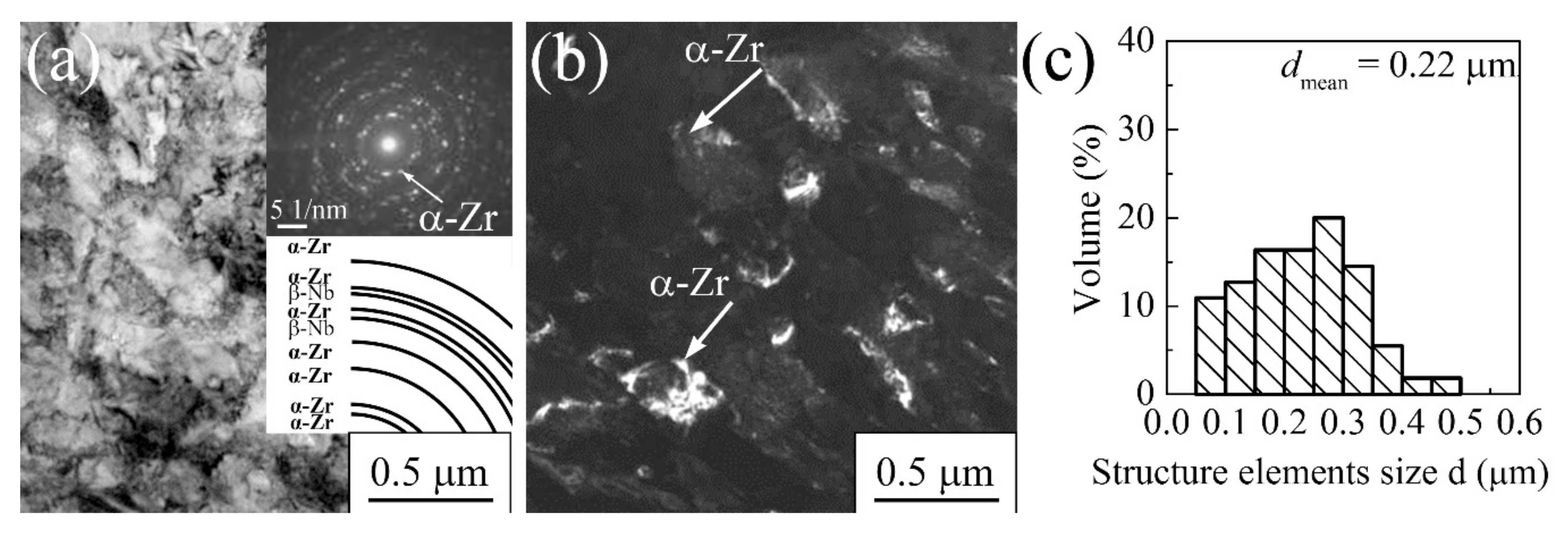
The initial microstructure of commercially pure titanium consists of equiaxial α-phase grains (hexagonal close-packed lattice/HCP-lattice), which are 10–45 µm in size and have an average value of 25 µm (Figure 4). Such grain-sized structures are classified as coarse-grained (CG), as described in the crystalline body classification system [95].
After combined SPD, which includes the above two methods, together with the subsequent annealing, NS and UFG states are formed in the billets. In the case of MDF with the inclusion of MPGR, the average size of the structure elements (grains, subgrains, fragments) is 0.2 μm, which corresponds to the UFG state [96]. PSC, including MPGR, enhances effective grain refinement; in this study, a nanostructure with characteristic sizes of structural elements of at least 100 nm [82] was obtained. According to the accepted terminology, NS materials [30] describe crystalline materials with an average grain size and other structural elements of at most 100 nm. Such materials, with a grain size from 100 nm to 1 µm, are called UFG [97].
A typical electron microscopic image of the titanium microstructure after MDF or PSC, including rolling and subsequent annealing, is shown in Figure 5. For comparative analysis, the titanium samples were deformed under the same temperature regimes. At the stages of forging and pressing, the temperature was reduced from 500 to 400 °C. After three cycles of cumulative deformation, e did not exceed 6.12, and after MPGR, it did not exceed 2.1.
No distinct grained structure was observed in the bright-field TEM images (Figure 5a,c). Both fragments (subgrains) and crystallized grains were observed. A dislocated lattice subgrain structure with insignificant dislocation density was localized inside the subgrains and fragments. The primary extinction contour was located along the boundaries of the grains and subgrains.
Numerous multi-varied isolated intensity reflexes arranged along the circles were observed on the microdiffraction images (Figure 5a, insert). This indicated large-angle disorientation at the grain boundaries. Several reflexes show azimuthal scattering, associated with a change in the crystal lattice in local areas.
The micro-diffraction image (Figure 5c) showed increasing circle discreteness (number of reflexes per unit of the circle arc) which was comparable to the number of reflexes observed in the micro-diffraction image (Figure 5a). This may be viewed as an indication that there is an increase in the number of structural elements per unit volume and, secondly, an increase in the angle between the subgrain boundaries.
Figure 6 shows the grain–subgrain structure pattern and the histogram of the size distribution of structural elements in the titanium after SPD. The average element structure size (grain, subgrain, and fragments) was calculated by the secant method [98]. As can be seen from the histogram, after MDF and MPGR, the fraction of structural elements with a size of 0.2 µm is 60% of the volume of the titanium sample, and the remaining 40% falls on elements with a size of 0.3–0.7 µm (Figure 6a,b). After PSC and MPGR, about 65% of the main volume consisted of structural elements with a size of 0.1 μm; the remaining structural elements had dimensions of 0.3–0.7 μm (Figure 6c,d).
Thus, both SPD methods produce the NS and UFG structures in titanium, while a high percentage of nanostructural elements is formed after MDF and MPGR.
The manifestation of the bulk NS and UFG structures via combined SPD methods increases the mechanical characteristics (yield strength, tensile strength, hardness, endurance limit, wear resistance, cyclic fatigue, etc.) [99,100,101,102,103,104,105,106]. This is due to the fact that NS and UFG metals have a number of specific characteristics, such as small grain size, the predominance of large-angle disorientation at the grain boundaries, and the predominance of high internal stresses as a result of significant defect density inside and at the subgrain and grain boundaries. The improvement of strength characteristics in parallel with a decrease in the grain size can be explained by grain boundary strengthening of the material, based on the Hall–Petch type of relationship [99,100,101,102].
Based on a uniaxial tensile test, the formation of NS and UFG structures in commercially pure titanium by the use of the combined SPD methods provided significantly improved strength characteristics (Figure 7a). The dependencies of σ = f(ε) represent the typical engineering curves for the elastic–plastic materials. The σtrue(εtrue) curve demonstrates a significant increase in the true stress for CG titanium in the “neck” region (Figure 7b). Since the destruction of the NS and UFG titanium under deformation occurs without the formation of a “neck”, the true and engineering curves are similar.
The yield strength in NS and UFG titanium increases by a factor of 3 and 2.2, respectively [87,88]. The plasticity before fracture is reduced to 6–7%. In this case, these strength characteristics of titanium are comparable with the strength characteristics of Grade 4 titanium alloys used in medicine: Ti–6Al–4V, Ti–6Al–7Nb (Table 1) [10,18].
Young’s modulus of titanium was determined according to the three-point bending scheme (Figure 7c). The corresponding values in the various states are shown in Table 1. In the CG state, Young’s modulus was 122 GPa. After applying the combined deformation method for the NS and UFG titanium, the modulus slightly decreased to 117 GPa (MDF and MPGR) and 100 GPa (PSC and MPGR), respectively (Table 1). The data for the NS titanium collected in Table 1 were obtained by the nanoindentation of the samples. High values of the elastic modulus in the range of 100–122 GPa are characteristic of pure titanium and are due to the presence of the main high-modulus α-phase.
Producing NS and UFG alloys is important for improving characteristics such as fatigue strength [103,104,105,106]. It leads to an increase in not only high-cycle (106 cycles) but also gigacycle (109 cycles or more) fatigue. When testing the high-cycle fatigue of CG titanium in the investigated range of cyclic stresses, failure occurred after N = 5 × 10⁴ cycles. At the cyclic stress amplitude of 280 MPa, the CG samples failed after 105 cycles. The number of cycles increased to N = 1.8 × 10⁶ before the destruction of UFG titanium
When testing gigacycle fatigue for CG titanium (Figure 7d) under the conditions of cyclic stress of 175 MPa, the CG samples failed after 105 cycles. The number of cycles increased to N = 1.9 × 10⁹ before the destruction of UFG titanium. Up to 109 cycles, the fatigue strength of UFG titanium was 200 MPa, which is 1.3 times higher than that of CG titanium [106].
When estimating the micro deformation of titanium, a quasistatic curve was recorded. Microplastic deformation in NS titanium develops much more slowly compared to the initial titanium, which, in turn, ensures high dimensional stability. Its resistance to micro deformations is significantly increased. The macroscopic elastic limit increases by up to 3 times (or even more) compared to the CG materials. The limited fatigue strength per 3 × 10⁶ cycles, and at a constant deformation range, is less than 300 MPa for CG titanium, while for NS titanium, it increases to 580 MPa [87].
The improvement of fatigue characteristics in NS and UFG titanium was due to increased resistance to the dislocation motion caused by the growing dislocation density within the grain volume itself. It is also worth mentioning the presence of long-range stress as well as the generation of the inhibition of new dislocations from the grain boundary, caused by the high non-equilibrium of the grain boundaries [99]. In addition, grain size reduction is expected to result in a decrease in the effective stress concentrators formed during the cyclic failure, which are caused by the transition to cooperative grain deformation.
Thus, the combined SPD methods of MDF and MPGR and pre-recrystallization annealing led to the formation of UFG titanium. Modification of the combined SPD method by replacing MDF with PSC made it possible to increase the grain refinement and the further development of NS titanium with an average size of structural elements of 100 μm. Based on the combined SPD methods, the formed nanostructure and the UFG states in titanium significantly improved the mechanical properties and support the practical application of titanium as a durable and reliable material for medical implants.

3.1.2. Zr-1Nb Alloy

The investigated annealed Zr-1Nb alloy has a polycrystalline structure with a grain size of 1–5 μm (Figure 8a). Electron microscopy revealed that the microstructure of the alloy contains α-Zr matrix grains and β-Nb particles, located at the boundaries and in the bodies of the matrix grains (Figure 8b). In zirconium, the dispersion strengthening of Nb particles predominates. In the microdiffraction image (Figure 8b, insert), the reflexes of the following phases were identified: the α-Zr phase (hexagonal close-packed/hcp lattice) and the β-Nb (body-centered cubic/BCC lattice). The reflexes of α-Zr were more pronounced, while those for β-Nb were less intense, indicating that the fraction of niobium is small. The grain size distribution of the α-Zr and β-Nb phases is shown in the histogram in Figure 8c,d. The average grain size of the α-Zr phase was 2.8 μm. The average particle size of Nb was 0.4 μm. The structure of a zirconium alloy with such a range of grain sizes, according to the classification in [95], should be considered to be a small-grained (SG) state.
The application of the combined SPD method, including MDF and MPGR, with further annealing at 300 °C, enhanced the formation of the UFG structure in the Zr-1Nb alloy [107,108,109].
Depending on the total (accumulative) strain value e, which can be as large as e = 1.5–4.6 after three, five, or nine pressings, the UFG structure is formed in the alloy at the MDF stage. An increase in the number of MDF cycles from one to three cycles reduces the average size of the structural element to 0.55–0.28 μm [90].
Subsequent MPGR leads to more efficient grain refinement and improves the structure homogeneity. A typical UFG microstructure of the Zr-1 wt % Nb alloy was formed after the application of single-cycle MDF (three pressings) (e = 2.12) and rolling (e = 2.01), as shown in Figure 9a,b.
The UFG microstructure in the Zr-1Nb alloy had a grain-subgrain structure, as seen in the titanium. The bright-field TEM images revealed the extinction contours passing through several boundaries of subgrains and fragments (Figure 9a). A high density of dislocations was observed in the grains, subgrains, and fragments.
In the microdiffraction pattern (Figure 9a, insert), a number of point reflexes can be seen, with a typical azimuthal blurring of different intensities, arranged in a circle. Microdiffraction identification of the zirconium alloy showed a high intensity of reflexes of the main α-phase (HCP lattice) and a low intensity of reflexes of the β-phase (BCC lattice). The average size of the structural elements, grains, subgrains, and fragments was about 0.22 µm.
According to the histogram demonstrating the size distribution of the structure elements (Figure 9c), about 37% of the volume falls on those elements with a size of 0.2 µm or less, and about 58% falls on the elements that are 0.2–0.4 µm in size. Elements with a size of 0.4 μm or more accounted for only about 4% of the distribution.
It should be noted that no niobium particles were observed on the bright-field TEM images. The particles of the β-Nb phase were identified by the energy-dispersive X-ray (EDX) microanalysis of the element content (Figure 10a,b). Their size was 40–60 nm. A decrease in the niobium particle size could be due to their partial dissolution during severe plastic deformation in a zirconium-based solid solution. This is characteristic of cementite during the plastic deformation of carbon steel [110].
The X-ray diffraction analysis revealed that the phase composition of the alloy after application of the combined SPD method did not change. The reflexes of the base phase α-Zr were identified in the microdiffraction pattern. The reflexes of the β-Nb phase revealed by the TEM analysis were not observed [111].
It is also worth noting that the use of various deformation methods for the Zr-Nb alloy systems, such as equal channel angular pressing (ECAP) and high-pressure torsion, enhanced the mechanical characteristics of the material, which, in turn, enhanced the formation of the UFG structure itself [77,78,79,80]. The combined SPD method, including MDF, MPGR, and pre-recrystallization annealing, led to the same effect.
Diagrams of the uniaxial tension (engineering stress-strain and true stress-true strain curves) for UFG zirconium alloys, produced by the MDF method and MPGR, are shown in Figure 11a,b. A significant increase in the true stress occurs in the Zr-1Nb alloy in both the SG and UFG states. This is due to the high plasticity and the formation of the “neck” in the Zr-1Nb alloy in both states.
After applying the SPD method, the yield strength σ0.2/YS and ultimate strength σYTS increased by up to 1.6 and 2 times, compared to the σ0.2/YS and σYTS of the SG alloy, respectively. At the same time, a high elongation value before deformation (12%) was observed (see Table 2). The plasticity before fracture for UFG zirconium alloy is comparable to the same characteristic in industrial zirconium. Table 2 presents the data for commercially pure zirconium obtained via electro-arc melting [111].
Three-point bending was applied to estimate Young’s modulus of the different structures of zirconium alloys (Figure 11c). Young’s modulus for the zirconium alloy in the SG state was 68 GPa, while Young’s modulus for UFG remained almost unchanged (66 GPa) after using the combined SPD method. It should be noted that Young’s modulus of zirconium-niobium alloy systems varies within 58–100 GPa, depending on the initial structure-phase state and the impurity content [111].
The fatigue strength increased in the UFG zirconium alloy under a gigacycle load regime [106]. Figure 12 illustrates the experimental fatigue points and curves for the zirconium alloy in different states.
The fatigue of the SG zirconium samples occurs in the low-cycle region if the number of cycles is less than 2.1 × 10⁴ and the stress amplitude is σ = 160 MPa. For the UFG zirconium alloy samples, the number of loading cycles before fracture is 1.5 × 10⁹ at stress σ = 170 MPa, which is 1.7 times higher than that for an alloy having that initial structure (the number of cycles before fracture is 1.7 × 10⁹, at a stress σ = 100 MPa).
Thus, the use of combined SPD methods, including MDF with subsequent MPGR and the pre-recrystallization annealing of the Zr-1Nb alloy, enhanced the formation of the UFG structure, providing increased strength and fatigue properties as well as a low Young’s modulus, in accordance with the requirements for medical implants.

3.1.3. Ti-45Nb Alloy

After billet quenching, a polyhedral-grained titanium and niobium solid-solution structure was formed in the initial Ti-45Nb alloy (body-centered cubic/BCC lattice). As is evident from Figure 13a, needle-shaped impurities can be observed in the grain volume bulk, which were attributed to a metastable martensitic α″-phase (orthorhombic lattice). The grain size ranged from 150 to 1700 µm, with an average grain size of 760 µm. More than 60% of the bulk volume falls on those grains that are 400–1200 µm in size (Figure 13b). The formation of such structures after quenching is typical for titanium-based alloys with a high niobium content of 30–45 wt %. [112,113].
The phase analysis based on the results of TEM SAED-patterns identification confirmed the presence of a β-solid solution of titanium and niobium, and a martensitic α″-phase (Figure 14a,b, insert). The martensite that is formed as a result of alloy annealing has a plate-like structure. A distinctive feature of the modification (Figure 14a, insert) is the appearance of low-intensity extra-reflex groups for the ω-phase (hexagonal primitive lattice/HPL). The segregation of the ω-phase is associated with heating the material above the polymorphic transformation point and with subsequent cooling under non-equilibrium conditions. This process mainly occurs in those regions depleted in the β-stabilizer—niobium [114]. Figure 14 shows the diagram of martensite identification, wherein the reflexes are highlighted as the axis area [ 2 ¯ 3 ¯ 1 ¯ ]α″, corresponding to the orthorhombic crystal lattice.
The results of electron microscopy are consistent with the X-ray diffraction analysis (XRD) (Figure 15a). The reflexes of the martensitic α″-phase and β-phase were identified by XRD. It should be noted that the ω-phase was not found here, due to an insignificant volume fraction of this phase.
After quenching, heterogeneity of physical and mechanical properties was observed in the Ti-Nb alloy. The hardness of the β-phase grains was in the range of 1400–1900 MPa, whereas the martensite α″-phase was 2800–3500 MPa.
The combined SPD method for the Ti-45Nb alloy included MDF and MPGR, followed by pre-recrystallization annealing at 300 MPa [115]. It should be noted that the α″-phase in the initial structure intensifies the process of structure fragmentation at the initial stage of SPD [72]. The phase content of the alloy changed after SPD, according to the XRD data (Figure 15b). As can be seen from the TEM data, after deformation, the metastable α″-phase was transformed into a stable β-phase, according to the scheme α″ →β + α [113].
Figure 16a,b illustrates the typical TEM images of the UFG Ti-45Nb alloy microstructure after three-cycle “abc”-pressing (e = 6.12) and MPGR (e = 2.01). The matrix elements (subgrains) of the β-phase were 0.1–0.3 μm in size, and the nano-subgrains of the α-phase were 20–60 nm in size; these were located at the intersections and boundaries of the matrix subgrains and can be observed on the bright-field TEM image.
Predominantly, the subgrains and fragments have an approximately equiaxed shape. In terms of the microdiffraction patterns of the Ti-45 wt % Nb alloy, three phase groups of reflexes can be distinguished (Figure 16a, insert): the high-intensity reflexes of the β-phase, the low-intensity reflexes of the α-phase titanium (HCP lattice), and the non-equilibrium ω-phase (hexagonal primitive lattice). The energy-dispersive X-ray (EDX) microanalysis showed that the niobium content in the β-phase subgrains is close to that of the initial state, 45 wt %, whereas the α-phase subgrains include 2–6 wt % of niobium. The concentration of the second component in both phases is in equilibrium [112].
Nanosized ellipsoidal ω-phase particles of up to 10 nm in size in the β-subgrain volume were observed on the dark-field TEM image of the ω-phase reflex (the reflex groups are indicated by a circle in Figure 16c, insert). It should be noted that the ω-phase was not identified on XRD. This is probably due to an insignificant fraction volume (3%, according to the TEM data).
According to the histogram demonstrating the distribution of the β-phase structure elements (subgrains), the bulk volume (up to 75%) corresponds to the subgrains between 0.1 and 0.3 µm, and only 5% of the volume falls on the subgrains between 0.4 and 0.5 µm in size (Figure 16d). The average size of the β-phase structure element in the Ti-45 wt % Nb alloy is 0.21 µm. Moreover, the α-phase subgrains, comprising 84% of the bulk volume, have a subgrain size of 0.02–0.04 µm. Subgrains of 0.05–0.07 µm comprise 12% of the volume, and subgrains with a size of less than 0.02 µm comprise only 4% (Figure 16e). The average α-phase subgrain size is 0.03 µm.
As in the case of titanium and the Zr-1Nb alloy, MDF and MPGR significantly improved the mechanical characteristics of the Ti-45Nb alloy (Figure 17). The engineering (Figure 17a) and the true (Figure 17b) curves for Ti-45Nb alloy in the CG and UFG states are similar to those for pure titanium. The effect of the “neck” in the Ti-45Nb alloy in the CG state is less pronounced and the increase in the true stress is not as significant as in the case of CG titanium.
As we can see from Figure 17a, for the UFG state of Ti-45Nb, the yield stress and the ultimate strength are increased by a factor of 1.2 and 1.6, respectively, in comparison to the CG state [115,116]. The ultimate plasticity for the UFG Ti-45Nb alloy is 6% (Table 3). For comparison, Table 3 demonstrates the properties of the industrial Ti-45Nb alloy [25,117].
By refining the structure of the Ti-45Nb alloy, the plasticity before fracture decreases to 6%. The decrease in the ductility of the alloys in the UFG state, as obtained by SPD, is usually associated with a general tendency for a rapid loss of plastic flow stability, due to the low ability of the material to tolerate strain-hardening [34,48,95]. It should be noted that, according to the results in previous studies [30,118], the limited strain at which the destruction of the UFG samples occurs during compression in the case of the Ti, Zr-1Nb, and Ti-45Nb alloy is at least 20%, which is 3 times larger than the plasticity before fracture seen in the tensile tests, in contrast with the fine-grained (FG) magnesium alloys produced by I-ECAP [41]. The true strain is practically the same under both compression and tension for FG magnesium alloys.
The Ti-45Nb alloy in the single-phase β-state has a low Young’s modulus (50–60 GPa) [18]. The structural-phase transformations in the alloy that occur during SPD can affect not only its strength properties but also its Young’s modulus. According to an earlier study [119], Young’s modulus of the phases contained in titanium alloys increases according to Eβ < Eα < Eω. The separation of the ω-phase particles leads to an enhancement of Young’s modulus. On the other hand, the nanostructuring of the β-titanium alloys by SPD can decrease its value. This is caused by the non-equilibrium of grain boundaries with dislocated substructures, due to the formation of long-range stress fields.
The initial value of 50 GPa of Young’s modulus was determined experimentally for the three-point bending of the UFG samples and the original titanium-niobium alloy (Figure 17c). Young’s modulus of the UFG alloy increased slightly to 58 GPa (Table 3).
The microhardness of the alloy after SPD was 3100 MPa. The distribution of microhardness was homogeneous over the UFG sample cross-section; under quenching conditions, it became heterogeneous, due to the presence of the α″-phase and the martensitic α″-phase grains (two-phase system).
Figure 18 shows the results of the gigacycle experiment for UGF and NS alloy samples obtained from the Ti-45Nb alloy. It was established that the UGF samples did not fail after 107 cycles at a maximum stress of 300 MPa or less. At the same time, the CG samples fail after 107 cycles at a maximum stress of 230 MPa. The fatigue limit for the UGF samples after 109 cycles was 290 MPa and, for the CG samples, it was 200 MPa. The samples with the UFG structure demonstrate an increased fatigue strength compared to CG structures. Thus, the fatigue limit (at 107 cycles) of the UGF Ti-45Nb alloy samples is 380 MPa, which, in turn, is approximately 1.4 times higher than the fatigue strength of the CG samples (σ0 = 280 MPa).
Thus, the multiphase UFG structure that appeared in the Ti-45Nb alloy as a result of combined SPD, represented by β-phase subgrains, dispersion-strengthened nanosized ω-phase particles, and ω-phase subgrains, provides a high level of mechanical properties and a low modulus of elasticity. The latter is comparable with Young’s modulus of cortical bone (10–55 GPa).

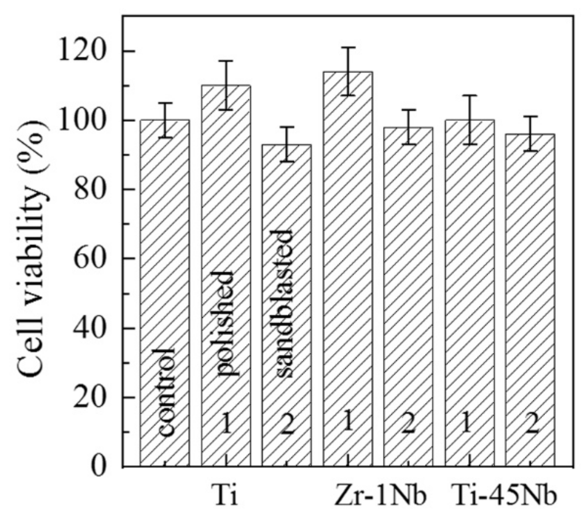
3.2. Biological Testing of UFG Titanium, Zr-1Nb, and Ti-45Nb Alloy

Two different states of the UFG titanium, zirconium–niobium, and titanium–niobium surfaces were used for biological testing, i.e., the polished state and the sandblasted state. The samples were successively polished with silicon carbide paper of 120, 480, and 600 μm in size, respectively. The polished samples were ultrasonically cleaned for 10 min in distilled water. The sandblasted samples were treated similarly, and then they were sandblasted with corundum (Al2O3) particles of 250–380 µm in size (Averon, Fryazino, Russia), as in an earlier study [15]. Finally, the samples were mechanically and ultrasonically cleaned in distilled water and ethanol, respectively. After ultrasonic cleaning, the polished and sandblasted Ti, Zr-1Nb, and Ti-45Nb samples were sterilized at 453 K for 60 min. The Ti, Zr-1Nb, and Ti-45Nb alloy had different surface roughness: the Ra value was 0.6–0.8 and 2–2.5 µm in the polished and sandblasted samples, respectively.

MTT Analysis Results

The MTT analysis data indicate the viability of the MG-63 osteosarcoma cells on the surfaces of Ti, Zr-1Nb, and Ti-45Nb samples after 10 days of cultivation. Cell culture on the surface of the plastic plates was used as control samples. The MTT analysis showed that the MG-63 cells proliferated well on the Ti, Zr-1Nb, and Ti-45Nb surfaces (Figure 19). Cell viability did not change and remained close to 100% for all substrates under study (Figure 19). The cell viability on the polished Ti, Zr-1Nb, and Ti-45Nb sample surface (1) was marginally higher compared to those on the sandblasted surface (2). Cell viability on the sandblasted Ti, Zr-1Nb, and Ti-45Nb surfaces slightly decreased, compared to the plastic control samples. This is due to the fact that additional energy is required for cell viability on a rough, sandblasted surface.
SEM analysis confirmed good adsorption of the MG-63 cells on the smooth polished and rough sandblasted surfaces (Figure 20, Figure 21 and Figure 22). In general, the MTT results of the Ti, Zr-1Nb, and Ti45Nb samples excluded cytotoxicity, indicating their high biocompatibility.

3.3. Development and Medical Applications of Dental Nanostructured Titanium Implants

Dental implantology is considered to be one of the most promising areas in dentistry; new methods of treating patients with complete or partial adentia are now being developed. Every year, hundreds and thousands of dental implants are installed worldwide. According to the Chicago Center for Advanced Dentistry, the global dental implant market was USD 3.4 billion in 2008. The US implant market was USD 1.7–2.0 billion in 2009 [120].
The market for dental implants and abutments in the Asia-Pacific region in 2008 amounted to USD 480 million. According to the Association of Dental Dealers in Europe (including more than 900 companies) and the European Dental Industry (more than 500 companies in ten European countries), the turnover of dental implants in Europe amounted to USD 144.4 million in 2001, which was 12.3% more than in 2000 [120].
Undoubtedly, the choice of material determines the functional reliability of dental implants. The material must not only be stable and flexible but it should also be safe and biocompatible with a living organism. Since 1951, after Branemark [8] discovered the phenomenon of osseointegration, pure titanium has become the standard material for dental implants.
Titanium fully meets the biocompatibility requirements but only partially meets the mechanical requirements. The point is that technically pure titanium samples (VT1-0 and VT1-00) are produced in Russia, while commercially pure titanium (four brands of Grade 1, 2, 3, and 4), different in composition and properties, is produced in the USA. One of the promising applications of high-strength NS and UFG titanium is dental implantology. This is due to two factors: only a small amount of titanium is required to make an implant at a reasonable price, and the working temperature of the implant is the body temperature itself.
Over the past 20 years, the Laboratory of Physics of Nanostructured Biocomposites of the Institute of Strength Physics and Materials Science, SB RAS (ISPMS SB RAS, Tomsk, Russia), has been developing biocomposites based on NS titanium alloys and biologically active CaP coatings. During this period, patents were issued to the Russian Federation (see Patent RF, 2385740 and Patent RF, 2441621).
Methods of severe plastic deformation contribute greatly to the formation of an NS/UFG homogeneous structure material with a grain and subgrain size of less than 100 nm. The developed VT1-0 NS/UFG titanium has mechanical properties that are comparable to those of some titanium alloys and does not contain hazardous alloying elements (A1, V, Mo, etc.). This, in turn, enhances the possibilities of the successful application of NS Ti in medicine. The appropriate preparation of the titanium surface, including mechanical treatment, sandblasting, and chemical etching, provides enhanced osseointegration, i.e., the attachment of the implant to the tooth tissue, in the absence of fibrous tissue between the implant and the tooth tissue. Studies of the morphological features of changes in bone tissue in the implant zone, in tests carried out on rabbits, showed that dental NS titanium implants show significantly improved osseointegration.
The modern designs of intraosseous dental screw implants of different modifications, including VT1-0 (VT1-00) NS/UFG titanium (characteristic of increased osseointegration), have been developed and patented at the ISPMS SB RAS, in collaboration with the Novokuznetsk State Institute of Advanced Medical Studies (Novokuznetsk, Russia), the Siberian Chemical Plant (Seversk, Russia), and the Siberian State Medical University (Tomsk, Russia).
The instruments and accessories necessary to perform surgical and orthopedic procedures with dental implants have been developed (technical specifications, number 942422.001–10). Pilot sets of dental-screw intraosseous implants, instruments, and accessories have been produced (Figure 23).
The clinical tests of NS titanium dental implants have confirmed that the implants meet the requirements of modern implantology, and their application does not generate complications during the surgical and orthopedic treatment stages. Today, the designed set of the NS titanium dental implants with instruments and accessories (technical specifications, number 942422.001–10) is recommended for stomatology in the Russian Federation and for registration in the Federal Supervisory Agency for Health Care and Social Development.
Bioinert metals and alloys in the NS and UFG states are the main components for producing effective biocomposites for medical applications. The most promising metal materials for substrates are bioinert pure titanium and Ti-45Nb alloy since they do not contain harmful and toxic chemical elements. In addition, Ti-Nb alloy has a low elastic modulus near the bone. The UFG and NC structures provide improved mechanical characteristics. Biotesting has proved the good osseointegration properties of these alloys. Therefore, the development and medical application of dental implants based on NS titanium are proposed.

4. Conclusions

The combined two-phase SPD method, including “abc” pressing into a symmetric channel, with multipass rolling and subsequent pre-recrystallization annealing, was developed to produce bulk VT1-0 titanium and Zr-1Nb and Ti-45Nb alloys billets with NS and UFG structures. The modification of the combined SPD method, due to the replacement of MDF with PSC, promotes more efficient grain refinement and makes it possible to obtain an NS state in VT1-0 titanium, with an average size of structural elements of 100 nm. The NS formed in pure VT1-0 titanium provides high yield strength, ultimate strength, fatigue limit, and microhardness (σ0.2/YS = 1100 MPa, σUTS = 1160 MPa, σ0 = 580 MPa, Hμ = 3200 MPa). The mechanical properties of NS titanium are comparable with medium-strength titanium alloys, such as Ti–6Al–4V and Ti–6Al–7Nb.
The combined SPD method, including MDF and MPGR, allows researchers to obtain a UFG structure (the average size of the structural elements is 0.2 μm) in Zr-1Nb alloys. The UFG structure provides about a 2-times increase in the mechanical properties of Zr-1Nb alloys (σ0.2/YS = 380 MPa, σUTS = 790 MPa, σ0 = 170 MPa, Hμ = 2800 MPa) in comparison with the SG state.
The multiphase UFG structure (the average size of the structural elements is 0.2 μm) formed in the Ti-45Nb alloy after MDF and MPGR, represented by subgrains of the main β-phase, dispersion-hardened nanosized particles of the ω-phase, and subgrains of the α-phase, provides a high level of mechanical properties at a low modulus of elasticity. The UFG structure provides an increase about 1.5 times that of the mechanical properties of the Ti-45Nb alloy (σ0.2/YS = 415 MPa, σUTS = 1180 MPa, σ0 = 380 MPa, Hμ = 3100 MPa) in comparison to the CG state. The modulus of elasticity of UFG Ti-45Nb alloy is comparable to that of cortical bone.
The plasticity before fracture, which is in the range of 6–12% for UFG alloys formed by SPD, may be considered satisfactory for producing implants.
MTT that was carried out for the VT1-0 titanium and Zr-1Nb and Ti-45Nb alloy samples in the UFG and/or NS states indicated their high biocompatibility. The cultivation of MG-63 osteosarcoma cells on the polished and sandblasted substrates demonstrated high cell viability after 10 days and good cell adhesion to the surface.
Thus, the NS and UFG alloys based on titanium, zirconium, and niobium, obtained by a combined SPD method including PSC or MDF and MPGR, present good biomaterials for medical applications, primarily for the replacement of bone parts that are lost, damaged, or infected with implants.

5. Patents

Bratchikov A.D., Sharkeev Yu.P., Kolobov Yu.R., Eroshenko A.Yu., Kalashnikov M.P. Method of deformation processing of materials and the device for its realization. Patent RF, 2315117, 2008 (in Russian).
Sharkeev Yu.P., Korobitsyn G.P., Tolmachev A.I., Eroshenko A.Yu., Belyavskaya O.A. The method of obtaining titanium blanks of polyhedral and round shapes in the nanostructured state and a device for deformation processing of titanium blanks. Patent RF, 2418092, 2011 (in Russian).
Legostaeva E.V., Sharkeev Y.P., Tolkacheva T.V., Tolmachev A.I., Uvarkin P.V. Bioactive coating on implant from titanium and method for its production. Patent RF, 2385740, 2010 (in Russian).
Sharkeev Yu.P., Polenichkin V.K., Belyavskaya O.A., Polenichkin A.V., Sheshukov S.I. Dental intraosseous implant and abutment for him. Patent RF, 2441621, 2012 (in Russian).

Author Contributions

Conceptualization, Y.S., A.E. and Z.K.; methodology, Y.S., A.E. and E.L.; investigation, A.E., E.L., M.K., O.P., V.S., Q.Z., Z.S. and H.Z.; resources, O.B., O.P., V.S., Q.Z., Z.S. and H.Z.; writing—original draft preparation, A.E. and Y.S.; writing—review and editing, Z.K., E.L. and M.E.; visualization M.K. and E.L.; supervision Y.S. and M.E. All authors have read and agreed to the published version of the manuscript.

Funding

The work was performed according to the Government Research Assignment for the Institute of Strength Physics and Materials Science of the Siberian Branch of the Russian Academy of Sciences (ISPMS SB RAS), project No. FWRW-2021-0004.

Institutional Review Board Statement

Not applicable.

Informed Consent Statement

Not applicable.

Data Availability Statement

Not applicable.

Acknowledgments

Experimental research was conducted using the equipment of the Common Use Center “Nanotech” at the Institute of Strength, Physics, and Materials Science, SB RAS (ISPMS SB RAS, Tomsk, Russia). The authors also would like to acknowledge the opportunities provided by the German Academic Exchange Service (DAAD; Leonhard-Euler program) in terms of exchange programs and the support of international collaboration. The authors are grateful to A.I. Tolmachev, P.V. Uvarkin, I.A. Glukhov, A.M. Mairambekova, O.B. Naimark, M.V. Bannikov, V.P. Vavilov, V.A. Skrypnyak, V.V. Fedorov, and Y.V. Dontsov for help and encouragement in the performance of the experiments.

Conflicts of Interest

The authors declare no conflict of interest.

References

  1. Tripathi, A.; Melo, J.S. (Eds.) Advances in Biomaterials for Biomedical Applications, Advanced Structured Materials; Springer: Singapore, 2017; 554p. [Google Scholar] [CrossRef]
  2. Tadic, D.; Epple, M. A thorough physicochemical characterisation of 14 calcium phosphate-based bone substitution materials in comparison to natural bone. Biomaterials 2004, 25, 987–994. [Google Scholar] [CrossRef]
  3. Niinomi, M.; Narushima, T.; Nakai, M. (Eds.) Advances in Metallic Biomaterials, Springer Series in Biomaterials Science and Engineering; Springer: Berlin/Heidelberg, Germany, 2015; 351p. [Google Scholar] [CrossRef]
  4. Kolken, H.M.A.; Janbaz, S.; Leeflang, S.M.A.; Lietaert, K.; Weinans, H.H.; Zadpoor, A.A. Rationally designed meta-implants: A combination of auxetic and conventional meta-biomaterials. Mater. Horiz. 2017, 5, 28–35. [Google Scholar] [CrossRef] [Green Version]
  5. Zhang, B.; Pei, X.; Zhou, C.; Fan, Y.; Jiang, Q.; Ronca, A.; D’Amora, U.; Chen, Y.; Li, H.; Sun, Y.; et al. The biomimetic design and 3D printing of customized mechanical properties porous Ti6Al4V scaffold for load-bearing bone reconstruction. Mater. Des. 2018, 152, 30–39. [Google Scholar] [CrossRef]
  6. Esposito, M.; Hirsch, J.M.; Lekholm, U.; Thomsen, P. Biological factors contributing to failures of osseointegrated oral implants, (II). Etiopathogenesis. Eur. J. Oral Sci. 1998, 106, 721–764. [Google Scholar] [CrossRef]
  7. Branemark, P.I.; Zarb, G.A.; Albrektsson, T. Tissue-Integrated Prostheses: Osseointegration in Clinical Dentistry; Quintessence Publishing Co.: Chicago, IL, USA, 1985; p. 350. [Google Scholar]
  8. Saini, M.; Singh, Y.; Arora, P.; Arora, V.; Jain, K. Implant biomaterials: A comprehensive review. World J. Clin. Cases 2015, 3, 52–57. [Google Scholar] [CrossRef]
  9. Niinomi, M.; Liu, Y.; Nakai, M.; Liu, H.; Li, H. Biomedical titanium alloys with Young’s moduli close to that of cortical bone. Regen. Biomater. 2016, 3, 173–185. [Google Scholar] [CrossRef] [Green Version]
  10. Ozaki, T.; Matsumoto, H.; Watanabe, S.; Hanada, S. Beta Ti Alloys with Low Young’s Modulus. Mater. Trans. 2004, 45, 2776–2779. [Google Scholar] [CrossRef] [Green Version]
  11. Niinomi, M. Mechanical properties of biomedical titanium alloys. Mater. Sci. Eng. A 1998, 243, 231–236. [Google Scholar] [CrossRef]
  12. Guo, S.; Meng, Q.; Zhao, X.; Wei, Q.; Xu, H. Design and fabrication of a metastable β-type titanium alloy with ultralow elastic modulus and high strength. Sci. Rep. 2015, 5, 14688. [Google Scholar] [CrossRef]
  13. Amarnath, G.; Muddugangadhar, B.; Tripathi, S.; Dikshit, S.; Divya, M.S. Biomaterials for Dental Implants: An Overview. Int. J. Oral Implant. Clin. Res. 2011, 2, 13–24. [Google Scholar] [CrossRef] [Green Version]
  14. Osman, R.B.; Swain, M.V. A Critical Review of Dental Implant Materials with an Emphasis on Titanium versus Zirconia. Materials 2015, 8, 932–958. [Google Scholar] [CrossRef] [Green Version]
  15. Colombo, M.; Gallo, S.; Padovan, S.; Chiesa, M.; Poggio, C.; Scribante, A. Influence of Different Surface Pretreatments on Shear Bond Strength of an Adhesive Resin Cement to Various Zirconia Ceramics. Materials 2020, 13, 652. [Google Scholar] [CrossRef] [Green Version]
  16. Zardiackas, L.; Freese, H.; Kraay, M. (Eds.) Titanium, Niobium, Zirconium, and Tantalum for Medical and Surgical Applications; ASTM: West Conshohocken, PA, USA, 2006; p. 265. [Google Scholar] [CrossRef]
  17. Brunette, D.M.; Tengvall, P.; Textor, M.; Thomsen, P. Titanium in Medicine: Material Science, Surface Science, Engineering, Biological Responses and Medical Applications, Engi-neering Materials; Springer: Berlin/Heidelberg, Germany, 2001; pp. 145–162. [Google Scholar]
  18. Niinomi, M.; Nakai, M.; Hieda, J. Development of new metallic alloys for biomedical applications. Acta Biomater. 2012, 8, 3888–3903. [Google Scholar] [CrossRef]
  19. Li, Y.; Yang, C.; Zhao, H.; Qu, S.; Li, X.; Li, Y. New Developments of Ti-Based Alloys for Biomedical Applications. Materials 2014, 7, 1709–1800. [Google Scholar] [CrossRef] [Green Version]
  20. Niinomi, M. Recent metallic materials for biomedical applications. Metall. Mater. Trans. A 2002, 33, 477–486. [Google Scholar] [CrossRef]
  21. Geetha, M.; Singh, A.K.; Asokamani, R.; Gogia, A.K. Ti based biomaterials, the ultimate choice for orthopaedic implants—A review. Prog. Mater. Sci. 2009, 54, 397–425. [Google Scholar] [CrossRef]
  22. Xu, L.-J.; Xiao, S.-L.; Tian, J.; Chen, Y.-Y.; Huang, Y.-D. Microstructure and dry wear properties of Ti-Nb alloys for dental prostheses. Trans. Nonferrous Met. Soc. China 2009, 19, s639–s644. [Google Scholar] [CrossRef]
  23. Hermann, R.; Calin, M.; Büchner, B.; Eckert, J. Elastic constants of single crystalline β-Ti70Nb30. Scr. Mater. 2012, 66, 198–201. [Google Scholar] [CrossRef]
  24. Gepreel, M.A.-H.; Niinomi, M. Biocompatibility of Ti-alloys for long-term implantation. J. Mech. Behav. Biomed. Mater. 2013, 20, 407–415. [Google Scholar] [CrossRef]
  25. Reck, A.; Pilz, S.; Thormann, U.; Alt, V.; Gebert, A.; Călin, M.; Heiß, C.; Zimmermann, M. Effects of thermomechanical history and environment on the fatigue behavior of (β)-Ti-Nb implant alloys. MATEC Web Conf. 2018, 165, 06001. [Google Scholar] [CrossRef]
  26. Zhou, F.; Wang, B.; Qiu, K.; Lin, W.; Li, L.; Wang, Y.; Nie, F.; Zheng, Y. Microstructure, corrosion behavior and cytotoxicity of Zr–Nb alloys for biomedical application. Mater. Sci. Eng. C 2012, 32, 851–857. [Google Scholar] [CrossRef]
  27. ASTM F2384-10; Standard Specification for Wrought Zirconium 2.5 Niobium Alloy for Surgical Implant Applications (UNS R60901). ANSI: New York, NY, USA, 2016.
  28. Buczynski, B.; Kory, M.; Steiner, R.; Kittinger, T.; Ramsier, R. Bacterial adhesion to zirconium surfaces. Colloids Surfaces B Biointerfaces 2003, 30, 167–175. [Google Scholar] [CrossRef]
  29. Narayan, R.J.; Hobbs, L.W.; Jin, C.; Rabiei, A. The use of functionally gradient materials in medicine. JOM 2006, 58, 52–56. [Google Scholar] [CrossRef]
  30. Valiev, R.Z.; Zhilyaev, A.P.; Langdon, T.G. Bulk Nanostructured Materials: Fundamentals and Applications; John Wiley & Sons, Inc.: Hoboken, NJ, USA, 2013; 456p. [Google Scholar] [CrossRef] [Green Version]
  31. Elias, C.N.; Meyers, M.A.; Valiev, R.Z.; Monteiro, S.N. Ultrafine grained titanium for biomedical applications: An overview of performance. J. Mater. Res. Technol. 2013, 2, 340–350. [Google Scholar] [CrossRef] [Green Version]
  32. Purcek, G.; Yapici, G.; Karaman, I.; Maier, H. Effect of commercial purity levels on the mechanical properties of ultrafine-grained titanium. Mater. Sci. Eng. A 2010, 528, 2303–2308. [Google Scholar] [CrossRef]
  33. Sergueeva, A.; Stolyarov, V.; Valiev, R.; Mukherjee, A. Advanced mechanical properties of pure titanium with ultrafine grained structure. Scr. Mater. 2001, 45, 747–752. [Google Scholar] [CrossRef]
  34. Valiev, R.Z.; Islamgaliev, R.K.; Alexandrov, I.V. Bulk nanostructured materials from severe plastic deformation. Prog. Mater. Sci. 2000, 45, 103–189. [Google Scholar] [CrossRef]
  35. Valiev, R.Z.; Langdon, T.G. Principles of equal-channel angular pressing as a processing tool for grain refinement. Prog. Mater. Sci. 2006, 51, 881–981. [Google Scholar] [CrossRef]
  36. Zhao, X.; Fu, W.; Yang, X.; Langdon, T.G. Microstructure and properties of pure titanium processed by equal-channel angular pressing at room temperature. Scr. Mater. 2008, 59, 542–545. [Google Scholar] [CrossRef]
  37. Zhu, Y.; Huang, J.; Gubicza, J.; Ungár, T.; Wang, Y.M.; Ma, E.; Valiev, R.Z. Nanostructures in Ti processed by severe plastic deformation. J. Mater. Res. 2003, 18, 1908–1917. [Google Scholar] [CrossRef] [Green Version]
  38. Meredith, C.S.; Khan, A.S. Texture evolution and anisotropy in the thermo-mechanical response of UFG Ti processed via equal channel angular pressing. Int. J. Plast. 2012, 30–31, 202–217. [Google Scholar] [CrossRef]
  39. Zhang, Y.; Figueiredo, R.B.; Alhajeri, S.N.; Wang, J.T.; Gao, N.; Langdon, T.G. Structure and mechanical properties of commercial purity titanium processed by ECAP at room temperature. Mater. Sci. Eng. A 2011, 528, 7708–7714. [Google Scholar] [CrossRef]
  40. Rosochowski, A. (Ed.) Severe Plastic Deformation Technology; Whittles Publishing: Scotland, UK, 2017; 264p. [Google Scholar]
  41. Gzyl, M.; Rosochowski, A.; Pesci, R.; Olejnik, L.; Yakushina, E.; Wood, P. Mechanical Properties and Microstructure of AZ31B Magnesium Alloy Processed by I-ECAP. Metall. Mater. Trans. A 2013, 45, 1609–1620. [Google Scholar] [CrossRef] [Green Version]
  42. Qarni, M.J.; Sivaswamy, G.; Rosochowski, A.; Boczkal, S. Effect of incremental equal channel angular pressing (I-ECAP) on the microstructural characteristics and mechanical behavior of commercially pure titanium. Mater. Des. 2017, 122, 385–402. [Google Scholar] [CrossRef] [Green Version]
  43. Zhilyaev, A.P.; Langdon, T.G. Using high-pressure torsion for metal processing: Fundamentals and applications. Prog. Mater. Sci. 2008, 53, 893–979. [Google Scholar] [CrossRef]
  44. Dimić, I.; Cvijović-Alagić, I.; Völker, B.; Hohenwarter, A.; Pippan, R.; Veljović, D.; Rakin, M.; Bugarski, B. Microstructure and metallic ion release of pure titanium and Ti–13Nb–13Zr alloy processed by high pressure torsion. Mater. Des. 2016, 91, 340–347. [Google Scholar] [CrossRef]
  45. Mohammed, M.T. Mechanical and wear properties of HPT-biomedical titanium: A review. Biomater. Biomech. Bioeng. 2015, 2, 185–196. [Google Scholar] [CrossRef]
  46. Zherebtsov, S.; Salishchev, G.; Galeyev, R.; Valiakhmetov, O.; Mironov, S.; Semiatin, S. Production of submicrocrystalline structure in large-scale Ti–6Al–4V billet by warm severe deformation processing. Scr. Mater. 2004, 51, 1147–1151. [Google Scholar] [CrossRef]
  47. Zherebtsov, S.; Salishchev, G.; Galeyev, R.; Maekawa, K. Mechanical Properties of Ti–6Al–4V Titanium Alloy with Submicrocrystalline Structure Produced by Severe Plastic Deformation. Mater. Trans. 2005, 46, 2020–2025. [Google Scholar] [CrossRef] [Green Version]
  48. Zherebtsov, S.; Kudryavtsev, E.; Kostjuchenko, S.; Malysheva, S.; Salishchev, G. Strength and ductility-related properties of ultrafine grained two-phase titanium alloy produced by warm multiaxial forging. Mater. Sci. Eng. A 2012, 536, 190–196. [Google Scholar] [CrossRef]
  49. Zherebtsov, S.; Salishchev, G.; Łojkowski, W. Strengthening of a Ti–6Al–4V titanium alloy by means of hydrostatic extrusion and other methods. Mater. Sci. Eng. A 2009, 515, 43–48. [Google Scholar] [CrossRef]
  50. Zherebtsov, S.; Lojkowski, W.; Mazur, A.; Salishchev, G. Structure and properties of hydrostatically extruded commercially pure titanium. Mater. Sci. Eng. A 2010, 527, 5596–5603. [Google Scholar] [CrossRef]
  51. Topolski, K.; Garbacz, H.; Wieciński, P.; Pachla, W.; Kurzydłowski, K. Mechanical properties of titanium processed by hydrostatic extrusion. Arch. Met. Mater. 2012, 57, 863–867. [Google Scholar] [CrossRef] [Green Version]
  52. Dinda, G.; Rösner, H.; Wilde, G. Synthesis of bulk nanostructured Ni, Ti and Zr by repeated cold-rolling. Scr. Mater. 2005, 52, 577–582. [Google Scholar] [CrossRef]
  53. Nocivin, A.; Raducanu, D.; Cinca, I.; Trisca-Rusu, C.; Butu, M.; Thibon, I.; Cojocaru, V.D. X-ray Diffraction Study and Texture Evolution for a Ti-Nb-Ta Biomedical Alloy Processed by Accumulative Roll Bonding. J. Mater. Eng. Perform. 2015, 24, 1587–1601. [Google Scholar] [CrossRef]
  54. Sadeghpour, S.; Abbasi, S.; Morakabati, M.; Karjalainen, L.; Porter, D. Effect of cold rolling and subsequent annealing on grain refinement of a beta titanium alloy showing stress-induced martensitic transformation. Mater. Sci. Eng. A 2018, 731, 465–478. [Google Scholar] [CrossRef]
  55. Li, S.J.; Cui, T.C.; Li, Y.L.; Hao, Y.L.; Yang, R. Ultrafine-grained β-type titanium alloy with nonlinear elasticity and high ductility. Appl. Phys. Lett. 2008, 92, 043128. [Google Scholar] [CrossRef]
  56. Xu, Y.; Yi, D.; Liu, H.; Wu, X.; Wang, B.; Yang, F. Effects of cold deformation on microstructure, texture evolution and mechanical properties of Ti–Nb–Ta–Zr–Fe alloy for biomedical applications. Mater. Sci. Eng. A 2012, 547, 64–71. [Google Scholar] [CrossRef]
  57. Cojocaru, V.; Raducanu, D.; Gloriant, T.; Gordin, D.; Cinca, I. Effects of cold-rolling deformation on texture evolution and mechanical properties of Ti–29Nb–9Ta–10Zr alloy. Mater. Sci. Eng. A 2013, 586, 1–10. [Google Scholar] [CrossRef] [Green Version]
  58. Gabrion, X.; Thibaud, S.; Zang, Y.; Charbonnier, P.; Laheurte, P.; Gaillard, Y. Effect of a hyper deformation drawing process on mechanical behaviour of thin wires of Ti-26Nb (at.%) alloys. Mater. Des. 2017, 120, 273–279. [Google Scholar] [CrossRef]
  59. Sordi, V.L.; Ferrante, M.; Kawasaki, M.; Langdon, T.G. Microstructure and tensile strength of grade 2 titanium processed by equal-channel angular pressing and by rolling. J. Mater. Sci. 2012, 47, 7870–7876. [Google Scholar] [CrossRef]
  60. Fan, Z.; Jiang, H.; Sun, X.; Song, J.; Zhang, X.; Xie, C. Microstructures and mechanical deformation behaviors of ultrafine-grained commercial pure (grade 3) Ti processed by two-step severe plastic deformation. Mater. Sci. Eng. A 2009, 527, 45–51. [Google Scholar] [CrossRef]
  61. Stolyarov, V.V.; Zhu, Y.T.; Lowe, T.C.; Valiev, R.Z. Microstructure and properties of pure Ti processed by ECAP and cold extrusion. Mater. Sci. Eng. A 2001, 303, 82–89. [Google Scholar] [CrossRef]
  62. Valiev, R.; Semenova, I.P.; Jakushina, E.; Latysh, V.; Rack, H.J.; Lowe, T.C.; Petruželka, J.; Dluhoš, L.; Hrušák, D.; Sochová, J. Nanostructured SPD Processed Titanium for Medical Implants. Mater. Sci. Forum 2008, 584-586, 49–54. [Google Scholar] [CrossRef]
  63. Semenova, I.P.; Korshunov, A.I.; Salimgareeva, G.K.; Latysh, V.V.; Yakushina, E.B.; Valiev, R.Z. Mechanical behavior of ultrafine-grained titanium rods obtained using severe plastic deformation. Phys. Met. Met. 2008, 106, 211–218. [Google Scholar] [CrossRef]
  64. Li, T.; Kent, D.; Sha, G.; Dargusch, M.S.; Cairney, J.M. Precipitation of the α-phase in an ultrafine grained beta-titanium alloy processed by severe plastic deformation. Mater. Sci. Eng. A 2014, 605, 144–150. [Google Scholar] [CrossRef]
  65. Zherebtsov, S.V.; Dyakonov, G.S.; Salishchev, G.A.; Salem, A.; Semiatin, S.L. The Influence of Grain Size on Twinning and Microstructure Refinement During Cold Rolling of Commercial-Purity Titanium. Met. Mater. Trans. A 2016, 47, 5101–5113. [Google Scholar] [CrossRef] [Green Version]
  66. Edalati, K.; Matsubara, E.; Horita, Z. Processing Pure Ti by High-Pressure Torsion in Wide Ranges of Pressures and Strain. Met. Mater. Trans. A 2009, 40, 2079–2086. [Google Scholar] [CrossRef]
  67. Panigrahi, A.; Sulkowski, B.; Waitz, T.; Ozaltin, K.; Chrominski, W.; Pukenas, A.; Horky, J.; Lewandowska, M.; Skrotzki, W.; Zehetbauer, M. Mechanical properties, structural and texture evolution of biocompatible Ti–45Nb alloy processed by severe plastic deformation. J. Mech. Behav. Biomed. Mater. 2016, 62, 93–105. [Google Scholar] [CrossRef]
  68. Elmay, W.; Prima, F.; Gloriant, T.; Bolle, B.; Zhong, Y.; Patoor, E.; Laheurte, P. Effects of thermomechanical process on the microstructure and mechanical properties of a fully martensitic titanium-based biomedical alloy. J. Mech. Behav. Biomed. Mater. 2013, 18, 47–56. [Google Scholar] [CrossRef] [PubMed]
  69. Eroshenko, A.; Sharkeev, Y.; Khimich, M.; Glukhov, I.; Uvarkin, P.; Tolmachev, A.; Mairambekova, A. Microstructure of ultrafine-grained Ti-40 wt.% Nb alloy after annealing. Lett. Mater. 2020, 10, 54–59. (In Russian) [Google Scholar] [CrossRef]
  70. Ozaltin, K.; Chrominski, W.; Kulczyk, M.; Panigrahi, A.; Horky, J.; Zehetbauer, M.; Lewandowska, M. Enhancement of mechanical properties of biocompatible Ti–45Nb alloy by hydrostatic extrusion. J. Mater. Sci. 2014, 49, 6930–6936. [Google Scholar] [CrossRef] [Green Version]
  71. Völker, B.; Jäger, N.; Calin, M.; Zehetbauer, M.; Eckert, J.; Hohenwarter, A. Influence of testing orientation on mechanical properties of Ti45Nb deformed by high pressure torsion. Mater. Des. 2017, 114, 40–46. [Google Scholar] [CrossRef]
  72. Panigrahi, A.; Bönisch, M.; Waitz, T.; Schafler, E.; Calin, M.; Eckert, J.; Skrotzki, W.; Zehetbauer, M. Phase transformations and mechanical properties of biocompatible Ti–16.1Nb processed by severe plastic deformation. J. Alloys Compd. 2015, 628, 434–441. [Google Scholar] [CrossRef]
  73. Ma, J.; Karaman, I.; Kockar, B.; Maier, H.; Chumlyakov, Y. Severe plastic deformation of Ti74Nb26 shape memory alloys. Mater. Sci. Eng. A 2011, 528, 7628–7635. [Google Scholar] [CrossRef]
  74. Edalati, K.; Horita, Z.; Yagi, S.; Matsubara, E. Allotropic phase transformation of pure zirconium by high-pressure torsion. Mater. Sci. Eng. A 2009, 523, 277–281. [Google Scholar] [CrossRef]
  75. Pérez-Prado, M.; Gimazov, A.; Ruano, O.; Kassner, M.; Zhilyaev, A. Bulk nanocrystalline ω-Zr by high-pressure torsion. Scr. Mater. 2008, 58, 219–222. [Google Scholar] [CrossRef]
  76. Zhilyaev, A.; Sabirov, I.; González-Doncel, G.; Molina-Aldareguía, J.; Srinivasarao, B.; Pérez-Prado, M. Effect of Nb additions on the microstructure, thermal stability and mechanical behavior of high pressure Zr phases under ambient conditions. Mater. Sci. Eng. A 2011, 528, 3496–3505. [Google Scholar] [CrossRef] [Green Version]
  77. Rogachev, S.O.; Rozhnov, A.B.; Nikulin, S.A.; Rybal’Chenko, O.V.; Gorshenkov, M.V.; Chzhen, V.G.; Dobatkin, S.V. Effect of torsion conditions under high pressure on the structure and strengthening of the Zr–1% Nb alloy. Phys. Met. Met. 2016, 117, 371–377. [Google Scholar] [CrossRef]
  78. Companhoni, M.V.P.; Matheus, J.R.G.; Marcondes, T.L.; Pinto, A.L. Analysis of microstructure and microhardness of Zr-2.5Nb processed by High-Pressure Torsion (HPT). J. Mater. Sci. 2012, 47, 7835–7840. [Google Scholar] [CrossRef]
  79. Grabovetskaya, G.P.; Stepanova, E.N.; Mishin, I.P.; Vinokurov, V.A. Effect of deformation and heat treatment on the structure, the mechanical properties, and the fracture characteristics of an ultrafine-grained Zr–1Nb alloy. Russ. Met. 2017, 2017, 271–278. [Google Scholar] [CrossRef]
  80. Kukareko, V.A.; Kopylov, V.I.; Kononov, A.G.; Rogachev, S.O.; Nikulin, S.A.; Dobatkin, S.V. Structural transformations during heating of a Zr-2.5% Nb alloy subjected to equal-channel angular pressing. Russ. Met. 2010, 2010, 642–647. [Google Scholar] [CrossRef]
  81. Straumal, B.; Gornakova, A.; Mazilkin, A.; Fabrichnaya, O.; Kriegel, M.; Baretzky, B.; Jiang, J.-Z.; Dobatkin, S. Phase transformations in the severely plastically deformed Zr–Nb alloys. Mater. Lett. 2012, 81, 225–228. [Google Scholar] [CrossRef]
  82. Terent’ev, V.F.; Dobatkin, S.V.; Nikulin, S.A.; Kopylov, V.I.; Prosvirnin, D.V.; Rogachev, S.O.; Bannykh, I. Fatigue strength of submicrocrystalline Ti and Zr–2.5% Nb alloy after equal channel angular pressing. Kov. Mater. 2011, 49, 65–73. [Google Scholar] [CrossRef]
  83. Nikulin, S.; Rozhnov, A.; Rogachev, S.; Khatkevich, V.; Turchenko, V.; Khotulev, E. Investigation of structure, phase composition, and mechanical properties of Zr-2.5% Nb alloy after ECAP. Mater. Lett. 2016, 169, 223–226. [Google Scholar] [CrossRef]
  84. Sharkeev, Y.; Eroshenko, A.; Kulyashova, K.; Fortuna, S.; Suvorov, K.; Epple, M.; Prymak, O.; Sokolova, V.; Chernousova, S. Microstructure, mechanical and biological properties of zirconium alloyed with niobium after severe plastic deformation. Mater. Und Werkst. 2013, 44, 198–204. [Google Scholar] [CrossRef]
  85. Kovalevskaya, Z.G.; Khimich, M.A.; Belyakov, A.V.; Shulepov, I.A. Evaluation of Physical and Mechanical Properties of Structural Components of Ti-Nb Alloy. Adv. Mater. Res. 2014, 1040, 39–42. [Google Scholar] [CrossRef]
  86. Sharkeev, Y.P.; Legostaeva, E.V.; Vavilov, V.P.; Skripnyak, V.A.; Belyavskaya, O.A.; Eroshenko, A.Y.; Glukhov, I.A.; Chulkov, A.O.; Kozulin, A.A. Regular Features of Stage Formation in the Stress-strain Curves and Microstructure in the Zone of Fracture of Coarse-Grained and Ultrafine-Grained Titanium and Zirconium Alloys. Sov. Phys. J. 2019, 62, 1349–1356. [Google Scholar] [CrossRef]
  87. Sharkeev, Y.P.; Legostaeva, E.V.; Eroshenko, Y.A.; Khlusov, I.A.; Kashin, O.A. The Structure and Physical and Mechanical Properties of a Novel Biocomposite Material, Nanostructured Titanium–Calcium-Phosphate Coating. Compos. Interfaces 2009, 16, 535–546. [Google Scholar] [CrossRef]
  88. Sharkeev, Y.P.; Vavilov, V.P.; Belyavskaya, O.A.; Skripnyak, V.A.; Nesteruk, D.A.; Kozulin, A.A.; Kim, V.M. Analyzing Deformation and Damage of VT1-0 Titanium in Different Structural States by Using Infrared Thermography. J. Nondestruct. Eval. 2016, 35, 42. [Google Scholar] [CrossRef]
  89. Humphreys, J.; Rohrer, G.S.; Rollet, A. Recrystallization and Related Annealing Phenomena, 3rd ed.; Elsevier: Amsterdam, The Netherlands, 2017; 734p. [Google Scholar]
  90. Sharkeev, Y.P.; Eroshenko, A.Y.; Danilov, V.I.; Tolmachev, A.I.; Uvarkin, P.V.; Abzaev, Y.A. Microstructure and Mechanical Properties of Nanostructured and Ultrafine-Grained Titanium and the Zirconium Formed by the Method of Severe Plastic Deformation. Sov. Phys. J. 2014, 56, 1156–1162. [Google Scholar] [CrossRef]
  91. Sharkeev, Y.; Vavilov, V.; Skrypnyak, V.; Legostaeva, E.; Eroshenko, A.Y.; Belyavskaya, O.; Ustinov, A.; Klopotov, A.; Chulkov, A.; Kozulin, A.; et al. Research on the processes of deformation and failure in coarse- and ultrafine-grain states of Zr1–Nb alloys by digital image correlation and infrared thermography. Mater. Sci. Eng. A 2020, 784, 139203. [Google Scholar] [CrossRef]
  92. Bannikov, M.V.; Naimark, O.B.; Oborin, V.A. Experimental investigation of crack initiation and propagation in high- and gigacycle fatigue in titanium alloys by study of morphology of fracture. Frat. Integrita Struttrale 2016, 35, 50–56. [Google Scholar] [CrossRef]
  93. Naimark, O.; Palin-Luc, T. Gigacycle fatigue: Non-local and scaling aspects of damage localization, crack initiation and propagation. Procedia Struct. Integr. 2016, 2, 1143–1148. [Google Scholar] [CrossRef] [Green Version]
  94. Betekhtin, V.I.; Kadomtsev, A.; Narykova, M.; Bannikov, M.; Abaimov, S.; Akhatov, I.; Palin-Luc, T.; Naimark, O.B. Experimental and theoretical study of multiscale damage-failure transition in very high cycle fatigue. Phys. Mesomech. 2017, 20, 78–89. [Google Scholar] [CrossRef] [Green Version]
  95. Glezer, A.M.; Kozlov, E.V.; Koneva, N.A.; Popova, N.A.; Kurzina, I.A. Plastic Deformation of Nanostructured Materials; CRC Press: Boca Raton, FL, USA, 2017; 334p. [Google Scholar] [CrossRef]
  96. Legostaeva, E.V.; Egorkin, V.S.; Sinebryukhov, S.L.; Eroshenko, A.Y.; Lyamina, G.V.; Komarova, E.; Gnedenkov, S.V.; Sharkeev, Y.P. Nanostructured titanium: Structure, mechanical and electrochemical properties. Inorg. Mater. Appl. Res. 2014, 5, 44–53. [Google Scholar] [CrossRef]
  97. Meyers, M.A.; Mishra, A.; Benson, D.J. Mechanical properties of nanocrystalline materials. Prog. Mater. Sci. 2006, 51, 427–556. [Google Scholar] [CrossRef]
  98. ASTM E1382-97; Standard Test Methods for Determining Average Grain Size Using Semiautomatic and Automatic Image Analysis. ANSI: New York, NY, USA, 2010. [CrossRef]
  99. Gleiter, H. Nanostructured materials: Basic concepts and microstructure. Acta Mater. 2000, 48, 1–29. [Google Scholar] [CrossRef] [Green Version]
  100. Dirras, G.; Tingaud, D.; Ueda, D.; Hocini, A.; Ameyama, K. Dynamic Hall-Petch versus grain-size gradient effects on the mechanical behavior under simple shear loading of β-titanium Ti-25Nb-25Zr alloys. Mater. Lett. 2017, 206, 214–216. [Google Scholar] [CrossRef]
  101. Wang, W.; Wang, X.; Mei, W.; Sun, J. Role of grain size in tensile behavior in twinning-induced plasticity β Ti-20V-2Nb-2Zr alloy. Mater. Charact. 2016, 120, 263–267. [Google Scholar] [CrossRef]
  102. Li, Y.; Bushby, A.J.; Dunstan, D.J. The Hall–Petch effect as a manifestation of the general size effect. Proc. R. Soc. A 2016, 472, 20150890. [Google Scholar] [CrossRef] [Green Version]
  103. Murakam, Y.; Nomoto, T.; Ueda, T. Factors influencing the mechanism of superlong fatigue failure in steels. Fatigue Fract. Eng. Mater. Struct. 1999, 22, 581–590. [Google Scholar] [CrossRef]
  104. Mughrabi, H. Specific features and mechanisms of fatigue in the ultrahigh-cycle regime. Int. J. Fatigue 2006, 28, 1501–1508. [Google Scholar] [CrossRef]
  105. Sharkeev, Y.P.; Kukareko, V.A.; Zinchenko, V.F.; Eroshenko, A.Y.; Kuchina, A.S. Increasing the cyclic life of submicrocrystalline and large-grain titanium in high-intensity ionic implantation. Steel Transl. 2010, 40, 729–732. [Google Scholar] [CrossRef]
  106. Naimark, O.B.; Sharkeev, Y.P.; Mairambekova, A.M.; Bannikov, M.V.; Eroshenko, A.Y.; Vedernikova, A.I. Failure mechanisms of titanium VT1−0 and zirconium alloy E110 in ultrafine-grained, fine-grained and coarse-grained states under cyclic loading in gigacycle regime. Lett. Mater. 2018, 8, 317–322. [Google Scholar] [CrossRef]
  107. Eroshenko, A.Y.; Mairambekova, A.M.; Sharkeev, Y.P.; Kovalevskaya, Z.G.; Khimich, M.A.; Uvarkin, P.V. Structure, phase composition and mechanical properties in bioinert zirconium-based alloy after severe plastic deformation. Lett. Mater. 2017, 7, 469–472. [Google Scholar] [CrossRef]
  108. Sharkeev, Y.P.; Eroshenko, A.Y.; Danilov, V.I.; Glukhov, I.A.; Tolmachev, A.I. Production of ultrafine-grain bioinert alloys. Steel Transl. 2015, 45, 116–119. [Google Scholar] [CrossRef]
  109. Sharkeev, Y.P.; Skripnyak, V.A.; Vavilov, V.P.; Legostaeva, E.V.; Kozulin, A.A.; Chulkov, A.O.; Eroshenko, A.Y.; Belyavskaya, O.A.; Glukhov, I.A. Special Aspects of Microstructure, Deformation and Fracture of Bioinert Zirconium and Titanium-Niobium Alloys in Different Structural States. Sov. Phys. J. 2018, 61, 1718–1725. [Google Scholar] [CrossRef]
  110. Kovalevskaya, Z.G.; Ivanov, Y.F.; Perevalova, O.B.; Klimenov, V.A.; Uvarkin, P.V. Study of microstructure of surface layers of low-carbon steel after turning and ultrasonic finishing. Phys. Met. Met. 2013, 114, 41–53. [Google Scholar] [CrossRef]
  111. Kondo, R.; Nomura, N.; Suyalatu; Tsutsumi, Y.; Doi, H.; Hanawa, T. Microstructure and mechanical properties of as-cast Zr–Nb alloys. Acta Biomater. 2011, 7, 4278–4284. [Google Scholar] [CrossRef]
  112. Bönisch, M.; Panigrahi, A.; Calin, M.; Waitz, T.; Zehetbauer, M.; Skrotzki, W.; Eckert, J. Thermal stability and latent heat of Nb–rich martensitic Ti-Nb alloys. J. Alloys Compd. 2017, 697, 300–309. [Google Scholar] [CrossRef]
  113. Sharkeev, Y.P.; Kovalevskaya, Z.G.; Khimich, M.A.; Bataev, V.A.; Zhu, Q.F.; Belyakov, A.V.; Gluhov, I.A. Phase Transformations of the Ti-40% Nb Alloy Under External Influence. Key Eng. Mater. 2016, 683, 174–180. [Google Scholar] [CrossRef]
  114. Colings, E.W. (Ed.) Physical Metallurgy of Titanium Alloys; American Society for Metals, Metals Park: Geauga County, OH, USA, 1984; 261p. [Google Scholar]
  115. Eroshenko, A.Y.; Sharkeev, Y.P.; Glukhov, I.A.; Uvarkin, P.V.; Mairambekova, A.M.; Tolmachev, A.I. The Influence of Dimesions and Phase State of Structural Elements on Mechanical Properties of Binary Alloys of the Ti–Nb and Zr–Nb Systems. Sov. Phys. J. 2019, 61, 1899–1907. [Google Scholar] [CrossRef]
  116. Sharkeev, Y.; Vavilov, V.; Skripnyak, V.A.; Belyavskaya, O.; Legostaeva, E.; Kozulin, A.; Chulkov, A.; Sorokoletov, A.; Eroshenko, A.; Kuimova, M. Analyzing the Deformation and Fracture of Bioinert Titanium, Zirconium and Niobium Alloys in Different Structural States by the Use of Infrared Thermography. Metals 2018, 8, 703. [Google Scholar] [CrossRef] [Green Version]
  117. Company Certificate ATI 45Nb™ Alloy, Allegheny Technologies Incorporated (ATI), Batch-No.TSC-522069. Available online: https://www.atimetals.com (accessed on 6 May 2022).
  118. Eroshenko, A.Y.; Sharkeev, Y.P.; Khimich, M.A.; Uvarkin, P.V.; Tolmachev, A.I.; Glukhov, I.A.; Legostaeva, E.V. Effect of Prolonged Thermal Exposure on Microstructure and Mechanical Properties of Zr–1 wt.% Nb and Ti–45 wt.% Nb Ultrafine-Grained Bioinert Alloys. Sov. Phys. J. 2021, 63, 1846–1853. [Google Scholar] [CrossRef]
  119. Lai, M.; Li, T.; Raabe, D. ω phase acts as a switch between dislocation channeling and joint twinning- and transformation-induced plasticity in a metastable β titanium alloy. Acta Mater. 2018, 151, 67–77. [Google Scholar] [CrossRef]
  120. Marketing in Dentistry. Chicago Center for Modern Dentistry. 2005. Available online: https://www.chicago-center.com (accessed on 5 May 2022).
Figure 1. MDF and MPGR: 1—initial billet (P—the arrows indicate the direction of applied load under pressing); 2—billet after first forging pass; 3–6—repeated forging passes with deformation axis rotation; 7—rolling; 8—billet formed after rolling in grooved rolls. “Reprinted with permission from ref. [88] Copyright 2022 Springer Nature”.
Metals 12 01136 g001
Figure 2. PSC and MPGR: 1—billet before first pressing cycle (P—the arrows indicate the direction of applied load under pressing); 2—billet after the first pressing cycle; 3—repeating previous pressing cycles by rotating deformation axis; 4—rolling; 5—billet configuration after rolling in grooved rollers.
Metals 12 01136 g002
Figure 3. Dependence of UFG titanium microhardness on annealing time and temperature “Reprinted with permission from ref [87] Copyright 2022 Springer Nature”.
Metals 12 01136 g003
Figure 4. Optical image (a), bright-field TEM image with corresponding microdiffraction pattern (b), histogram of the structure element size distribution of CG titanium (c).
Metals 12 01136 g004
Figure 5. Bright-field with corresponding microdiffraction patterns (a,c) and dark field (b,d) TEM images of titanium produced by MDF and MPGR (a,b), and PSC and MPGR (c,d).
Metals 12 01136 g005
Figure 6. Areas of bright-field TEM images (a,c) of the grain–subgrain structures, and histograms of element structure size distribution (b,d) of the titanium processed with MDF and MPGR (a,b) and PSC and MPGR (c,d).
Metals 12 01136 g006
Figure 7. The tensile engineering stress-strain curves (a), true stress-true strain curves (b), three-point bending diagram (c), and the dependence of stress σ on the number of fatigue cycles (N) (d) for pure titanium; 1—CG state, 2—UFG produced by MDF and MPGR, 3—NS, produced by PSC and MPGR. Arrows indicate those samples that did not fail during testing.
Metals 12 01136 g007
Figure 8. Optical image (a) and bright-field TEM image, with corresponding microdiffraction pattern (b); histograms of the element structure size distribution of the α-Zr phase (c) and β-Nb phase (d) of Zr-1Nb alloy in SG state.
Metals 12 01136 g008
Figure 9. Bright-field with corresponding microdiffraction pattern (a) and dark field (b) TEM images, with the distribution histogram of structure element sizes (c) of Zr-1Nb alloy after MDF and MPGR.
Metals 12 01136 g009
Figure 10. Niobium distribution map of Zr-1Nb alloy: bright field (a) and dark field (b) TEM images.
Metals 12 01136 g010
Figure 11. Tensile engineering stress-strain curves (a) and true stress-true strain curves (b), and three-point bending diagram (c) of the Zr-1Nb alloy; 1—SG state, 2—UFG state.
Metals 12 01136 g011
Figure 12. The dependence of stress σ on the number of fatigue cycles N for the Zr-1Nb alloy: 1—SG state; 2—UFG state. Arrows indicate those samples that did not fail during testing.
Metals 12 01136 g012
Figure 13. Optical image (a) and histogram of the structural element size distribution (b) of Ti-45Nb alloy.
Metals 12 01136 g013
Figure 14. Bright-field image with corresponding microdiffraction patterns in TEM images (a,b) and the α″-phase identification (c) of Ti-45Nb alloy under quenching: (a)—β-phase; (b)—α″-phase.
Metals 12 01136 g014
Figure 15. XRD pattern of Ti-45Nb alloy (Cu-Kα) after quenching (a) and with UFG (b).
Metals 12 01136 g015
Figure 16. Bright-field (a) and dark-field (b,c) TEM images, with corresponding microdiffraction patterns and histograms of the structure element size distribution of β-phase (d) and α-phase (e) of UFG Ti-45Nb, after MDF and MPGR.
Metals 12 01136 g016
Figure 17. Tensile engineering stress-strain curves (a) and true stress-true strain curves (b), and three-point bending diagram (c) of Ti-45Nb alloy: 1—CG state, 2—UFG state.
Metals 12 01136 g017
Figure 18. Dependence of the stress σ on the number of fatigue cycles N for the Ti-45Nb alloy: 1—CG state; 2—UFG state. Arrows indicate the samples that did not fail during the testing.
Metals 12 01136 g018
Figure 19. MTT analysis of the titanium, Zr-1Nb, and Ti-45Nb samples after MG-63 cell incubation for 10 days. Control: plastic plate; 1—polished samples, 2—sandblasted samples.
Metals 12 01136 g019
Figure 20. MG-63 osteosarcoma cells on a titanium sample surface after incubation for 10 days: (a,b)—titanium polished samples; (c,d)—titanium sandblasted samples.
Metals 12 01136 g020
Figure 21. MG-63 osteosarcoma cells on the Zr-1Nb sample surface after incubation for 10 days: (a,b)—Zr-1Nb polished samples; (c,d)—Zr-1Nb sandblasted samples.
Metals 12 01136 g021
Figure 22. MG-63 osteosarcoma cells on Ti-45Nb sample surface after incubation for 10 days: (a,b)—Ti-45Nb polished samples; (c,d)—Ti-45Nb sandblasted samples.
Metals 12 01136 g022
Figure 23. SEM images of the NS implant surface after mechanical treatment (a); a set of dental screw intraosseous implants, with instruments and accessories (b); X-ray topographic images of the internal cross-sectional dental implants (c).
Metals 12 01136 g023
Table 1. The mechanical properties of titanium alloys for medical applications.
Materialsσ0.2/YS, MPaσUTS,
MPa
ε, %σf,
MPa
Hμ, MPaE, GPa
Pure Ti
CG state
270400232801800122
UFG Ti
(MDF and MPGR)
870107073002700–2800117
NS Ti
(PSC and MPGR)
1100116065803000–3200100
Grade 4≥480≥550154702200114
Ti–6Al–4V10101100≥8570350088–116
Ti–6Al–7Nb82094072000110–120
Note: σ0.2/YS—yield strength; σUTS—ultimate stress; ε—plasticity value; σf—fatigue limit for 106 cycles; Hμ—microhardness; E—Young’s modulus.
Table 2. Mechanical properties of zirconium Zr-1Nb alloy.
Materialsσ0.2/YS, MPaσUTS,
MPa
ε, %σf,
MPa
Hμ, MPaE, GPa
Zr-1Nb
SG state
23039026100154068
UFG Zr-1Nb38079012170280066
Zr (in billets)3053901595
Note: σ0.2/YS—yield strength; σUTS—ultimate strength; ε—plasticity value; σf—fatigue for 106 cycles; Hμ—microhardness; E—Young’s modulus. 1
Table 3. Mechanical properties of the Ti-45Nb alloy.
Materialsσ0,2/YS, MPaσUTS,
MPa
ε, %σf,
MPa
Hμ, MPaE, GPa
Ti-45Nb
(CG state)
34571014.5280230050
UFG Ti-45Nb41511806380310058
Ti-45Nb
industrial
4506551030062
Note: σ0.2/YS—yield strength; σUTS—ultimate stress; ε—plasticity value; σf—fatigue limit for 106 cycles; Hμ—microhardness; E—Young’s modulus. 5
Publisher’s Note: MDPI stays neutral with regard to jurisdictional claims in published maps and institutional affiliations.

