Article

Effect of Quenching and Tempering on Mechanical Properties and Impact Fracture Behavior of Low-Carbon Low-Alloy Steel

1
Collaborative Innovation Center of Steel Technology, University of Science and Technology Beijing, Beijing 100083, China
2
Technical Quality Department, Xiangtan Iron & Steel Group Co., Ltd., Xiangtan 411101, China
*
Author to whom correspondence should be addressed.
Metals 2022, 12(7), 1087; https://doi.org/10.3390/met12071087
Submission received: 3 June 2022 / Revised: 22 June 2022 / Accepted: 22 June 2022 / Published: 25 June 2022
(This article belongs to the Special Issue Structure and Properties of Heterogeneous Materials)

Abstract

:
Conventional quenching and tempering were employed to achieve the optimal strength and toughness of low-carbon low-alloy steel. The fracture behavior (crack initiation and propagation) of the steel in the impact process was also analyzed. It was found that the microstructures of the steel after different tempering treatments were mainly composed of martensite, and its mechanical properties were dependent on the tempering temperature. With the increase in tempering temperature, martensitic laths merged and coarsened. Moreover, recovery occurred, causing a decrease in dislocation density. Subsequently, the strength of the steel gradually decreased, and the impact energy increased. When the tempering temperature was 600 °C, the optimal yield strength (557 MPa) and the impact energy (331 J) were achieved. In addition, high angle grain boundaries (HAGBs) affected the impact energy and crack propagation. Cracks were easily deflected when they encountered high angle grain boundaries, and linearly expanded when they encountered low angle grain boundaries (LAGBs).

1. Introduction

As one of the keys to the decarbonization and zero emissions of energy systems, offshore platforms are becoming increasingly important. Further, the development of offshore platforms can promote the efficient utilization of green energy and help achieve peak emissions and carbon neutrality. Offshore platform steels play an important role in ensuring the safety of marine structures. Under strong waves, tides, storms, and other severe marine environments, steels with high strength and toughness are available to improve safety and stability [1,2,3,4,5]. In these situations, low-carbon low-alloy steels are greatly favored because of their excellent strength and cryogenic toughness [6].
Strength and toughness are the most important indexes of steel. The strength of low-carbon low-alloy steel can be compensated by precipitation strengthening and fine grain strengthening. In the current research scenario, how to maximize toughness without losing strength has become the main concern for engineers [7,8,9]. Martensite is one of the main phases of low-carbon high-strength steel. After quenching, high-density dislocations inside martensitic laths can contribute to grain boundary strengthening, precipitation strengthening and solid solution strengthening [7,10,11]. S.W. Thompson found that low-carbon martensite caused the best strength and toughness matching, followed by low carbon bainite and polygonal ferrite [12]. However, martensite becomes extremely hard and brittle after water-quenching, due to carbon solid solution strengthening. Therefore, it is necessary to temper martensite after quenching to further improve its toughness [13,14,15]. Sun et al. reported that quenching effectively controlled the carbon content of the steel matrix and the substructure size of martensitic laths, and tempering promoted the formation of spherical carbides and improved the impact toughness [16]. Zhao et al. found that low-carbon steel prepared by conventional quenching and tempering had a cryogenic toughness of 69 J at −40 °C because of the presence of martensite and fine film-like stable austenite [8]. Chen et al. developed ultra-low-carbon, high-strength steel, and found that the optimum combination of strength and toughness could be obtained by controlling the cooling rate after direct quenching [11]. Therefore, the optimum combination of strength and toughness can be obtained by regulating microstructure and heat treatment.
Microstructures greatly affect crack initiation and propagation, and the toughness of steel can be improved by hindering crack propagation [17,18]. Toughness is directly related to fracture resistance. Fracture generally occurs in three stages: local stress concentration, microvoid formation and crack propagation [19,20]. The initiation and propagation of cracks result from the interaction between dislocation substructures and other microdefects in martensite. Thus, the toughness of steel can be improved to a certain extent by hindering crack propagation. Crack propagation is influenced by the percentages of high angle grain boundaries and low angle grain boundaries [11,19,20,21]. In summary, it is necessary to investigate the relationships between microstructure, cracks and cryogenic toughness.
In the present work, the microstructure of the low-carbon low-alloy steel was regulated by conventional quenching and tempering to obtain the optimal strength and toughness matching. The relationship between the initiation and propagation of cracks and microstructure was investigated to provide theoretical support for improving toughness.

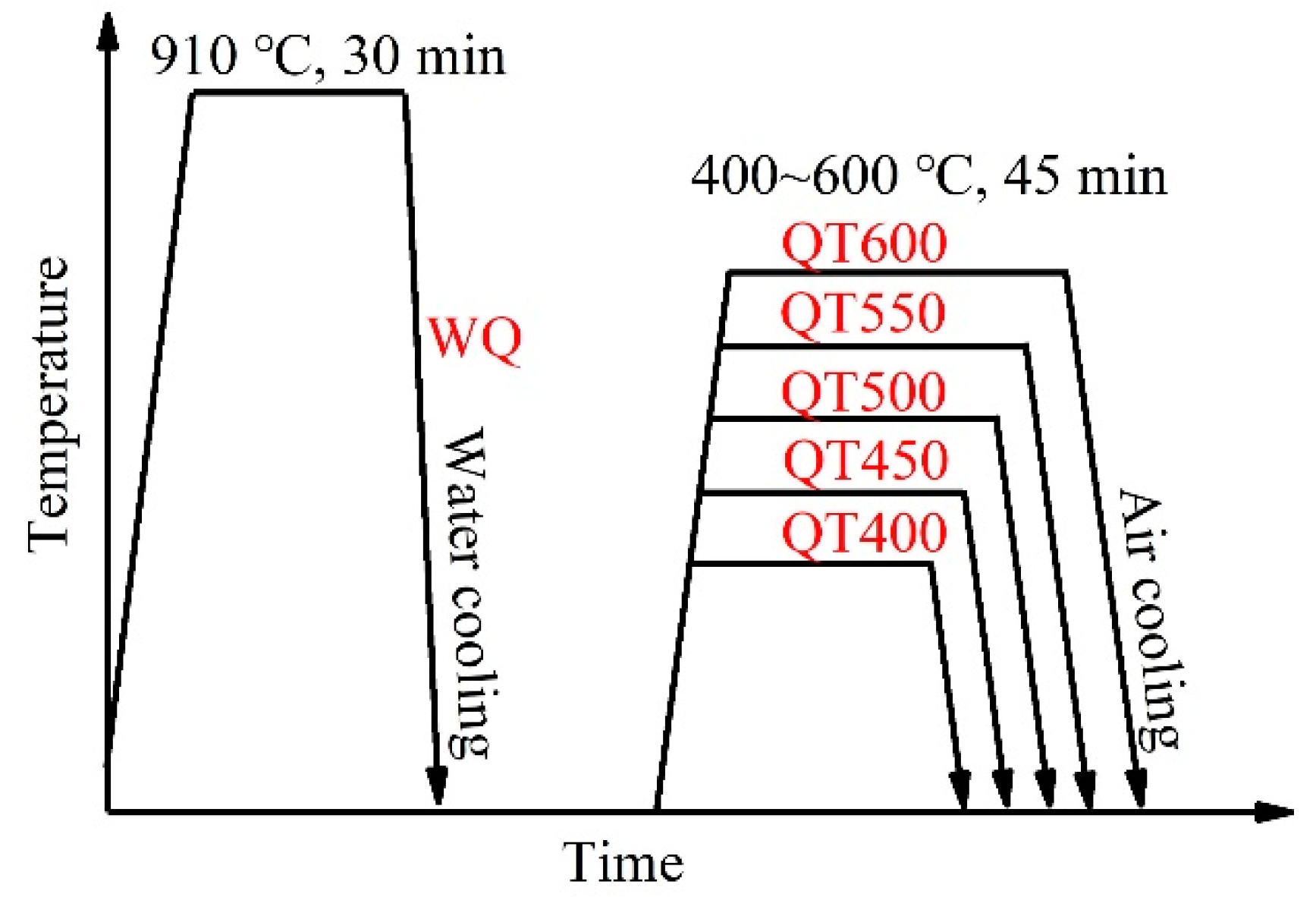
2. Materials and Methods

The chemical composition of the low-carbon low-alloy steel is presented in Table 1. The steel was vacuum-melted and cast into a 25 kg ingot, which was reheated at 1200 °C for six hours and forged into a 70 mm thick plate. The forged steel plate was then hot-rolled to 14 mm thickness. The heat treatment process is displayed in Figure 1. The steel specimens were first austenitized at 910 °C for 30 min and then water-quenched (WQ) to room temperature. The specimens were separately tempered at 400 °C, 450 °C, 500 °C, 550 °C and 600 °C for 45 min, and then air-cooled. The specimens with different heat treatments were named QT400, QT450, QT500, QT550 and QT600, respectively.
According to the GB/T 228.1-2010 standard, tensile tests of plate specimens (gauge length = 25 mm) were carried out on an electronic universal tensile testing machine. According to the GB/T 229-2007 standard, Charpy V-notched impact specimens of 10 mm × 10 mm × 55 mm size were tested at −40 °C on a 450 J impact tester. In each group, three specimens were tested, and the average value was adopted to reduce the experimental error.
After mechanical grinding and polishing, the specimens were etched with 4% nital solution for ten seconds, and the microstructures were observed by a Gemini 500 scanning electron microscope (SEM). The specimens were electro-polished in 10% perchloric acid and alcohol at the potential of 18 V for 25 s, and then the average misorientation angles and the percentage of HAGBs were measured by electron backscatter diffraction (EBSD, Symmetry S2). The scanning step size was 0.15 μm. After double-jet electrolytic thinning in a solution of 10% perchloric acid alcohol, martensitic laths, dislocation and sub-grains were detected by an FEI Tecnai F20-FEGTM transmission electron microscope (TEM). The dislocation densities of the specimens were measured by a Bruker D8 Advance X-ray diffractometer (XRD) under Cu-Kα radiation at 40 kV and 40 mA. The scanning angle during XRD ranged between 35° and 145°, and the scanning speed was 1°/min. The dislocation density was calculated by the formula [22,23]:
ρ = K e 2 b 2
where K is a constant (14.4, for BCC crystal structure material), ρ is the dislocation density of martensite, e is the micro-strain calculated by MDI Jade 6.0 software, and b is the Burgers vector of martensite.

3. Results

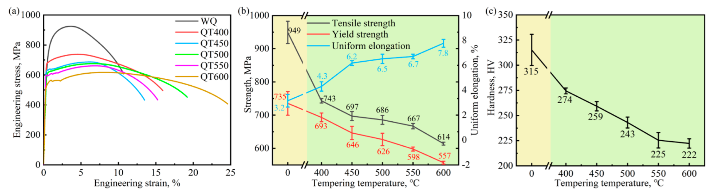
3.1. Mechanical Properties

Figure 2 shows the tensile properties of the specimens after different heat treatments. The yield strength, tensile strength and uniform elongation of the water-quenched specimen were 735 MPa, 949 MPa and 3.2%, respectively. Compared with these values, the yield strength, tensile strength and uniform elongation of the specimens tempered at 400 °C decreased by 26 MPa, decreased by 187 MPa, and increased by 1.1%, respectively. The yield strength and tensile strength of the specimens gradually decreased with the increase in the tempering temperature. However, the decrement degree was relatively small. The uniform elongation of the specimens increased continuously with the increase in tempering temperature. The hardness of the water-quenched specimen was 315 HV, whereas that of the tempered specimen at 400 °C decreased by 41 HV. Similar to the strength variation trend, the hardness of the specimens gradually decreased with the increase in tempering temperature.
The impact energies of the specimens after being tempered at different temperatures are shown in Figure 3. When the tempering temperatures were 0 °C, 400 °C, 450 °C, 500 °C, 550 °C and 600 °C, the impact energies were 215 J, 287 J, 290 J, 296 J, 284 J and 331 J, respectively. After water-quenching, the impact energy of the specimens tempered at 400 °C increased the most. When the tempering temperature rose from 400 °C to 550 °C, the impact energy changed slightly. When the tempering temperature rose from 550 °C to 600 °C, the impact energy significantly increased. Generally, the impact energy increased with the increase in tempering temperature. Notably, the impact energy (284 J) of the specimen tempered at 550 °C was lower than that of all other tempered specimens. In other words, the tempering embrittlement temperature of the studied low-carbon low-alloy steel was around 550 °C. The main goal of this research was to obtain better strengthening and toughness matching, rather than excellent toughness or strength alone. As seen in Figure 3b, with reasonable composition and heat treatment, the tested steel manifested better strength and toughness matching than other low-carbon low-alloy steels.

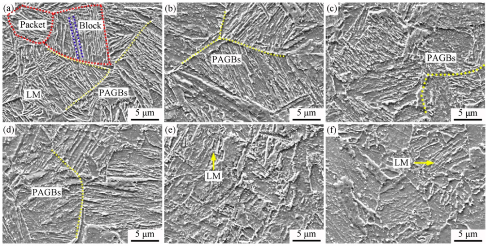
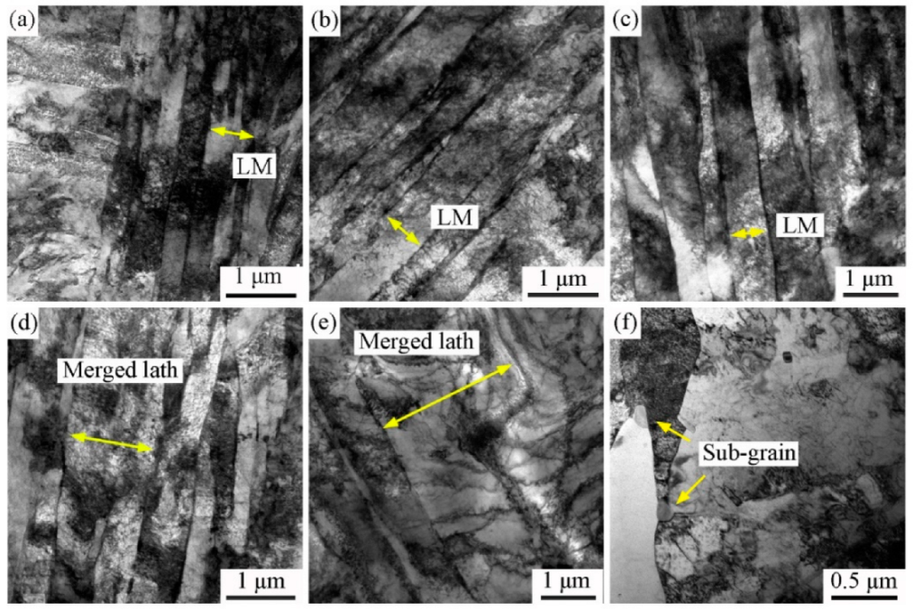
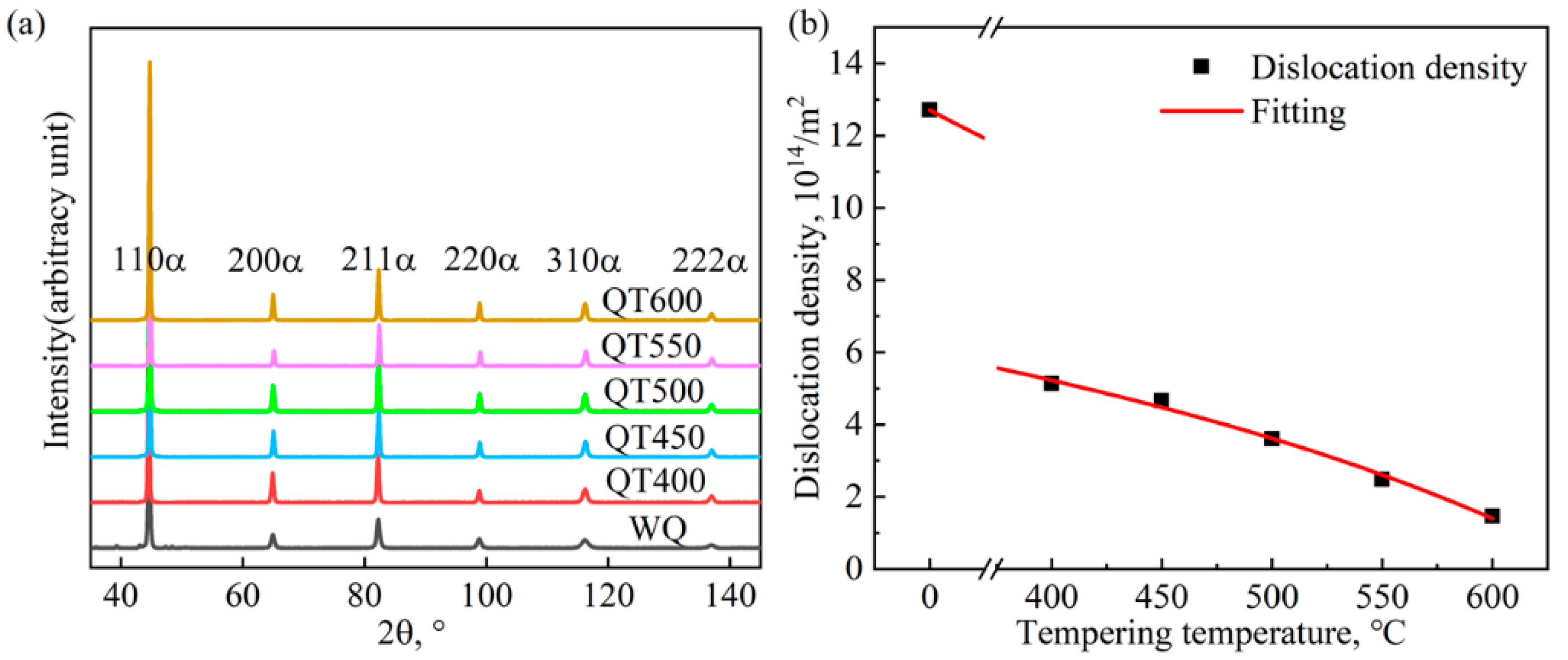
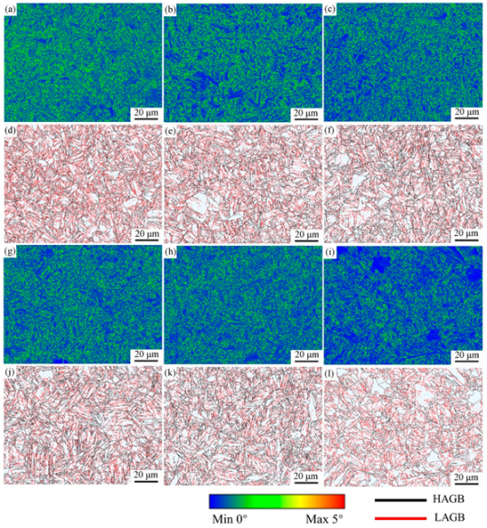
3.2. Microstructure Characterization
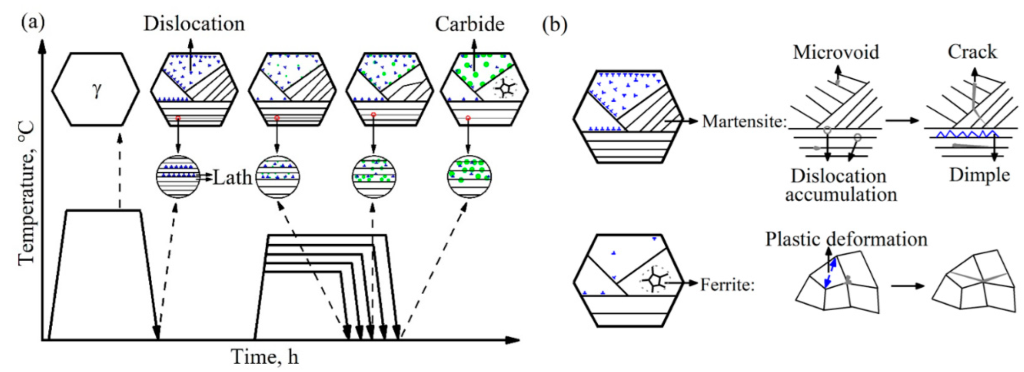
The microstructure of the water-quenching specimen mainly contained homogeneous martensite, as shown in Figure 4a. The prior austenite grain boundaries (PAGBs, marked by yellow dotted lines) and lath martensite (LM, marked by arrows) can be observed clearly. Each prior austenite grain was composed of several packets (marked by red dotted lines) with different orientations, and each packet consisted of parallel blocks (marked by blue dotted lines). Figure 4b–f indicate that the characteristics of martensite were gradually weakened with the increase in tempering temperature, and the microstructure was mainly tempered martensite. The martensitic laths were relatively clear when the tempering temperature was 400 °C and 450 °C. However, the martensitic laths gradually became blurred after tempering at 500 °C, 550 °C and 600 °C. Especially at 600 °C, the martensitic laths decomposed the most, and the number of martensitic laths decreased. The prior austenite grain boundaries became significantly blurred.
TEM micrographs of different specimens are shown in Figure 5. Figure 5a reveals the presence of numerous dislocation tangles between the martensitic laths, and Figure 5b indicates that the martensitic laths remained straight after tempering at 400 °C. Dislocation offset and annihilation accelerated, and the rate of dislocation proliferation was lower than that of dislocation extinction. When the tempering temperature reached 450 °C, the martensitic laths gradually became bent and tended to merge (Figure 5c). After this, the martensite greatly recovered and maintained its lath-like morphology. Some martensitic laths disappeared, and a part of the remaining laths merged after tempering at 500 °C and 550 °C (Figure 5d,e, marked by yellow arrows). Therefore, the number of dislocations was also substantially reduced due to the fast rate of dislocation extinction, and the remaining dislocations underwent polygonization. When the tempering temperature was 600 °C, sub-grains were formed (Figure 5f, marked by yellow arrows).
Figure 6a displays the XRD patterns of the specimens after different heat treatments, and the peaks are all BCC peaks. The dislocation densities were quantified by evaluating the six peaks, as shown in Figure 6b. The dislocation density of the water-quenched specimen was calculated as 1.27 × 10¹⁵ m−2. After tempering at 400 °C, the number of dislocations decreased sharply, and nearly half of these dislocations were annihilated. Thereafter, the dislocation density decreased slightly during tempering at 450~600 °C.
Figure 7 shows the impact fracture morphologies of the specimens after different heat treatments. In the sub-figures, as shown by the yellow arrow, Figure 7(a1–f1) are the bottom magnification of the specimens, Figure 7(a2–f2) are the central magnification of the specimens, and Figure 7(a3–f3) is the near notch magnification of the specimens. It is noticeable that all specimens mainly experienced a ductile fracture. The fracture surfaces were composed of a large number of dimples of uneven size, depth and shape. Microvoids existed on the fracture surface of the specimens, especially at the bottom of the dimples, as shown by the red arrows. Cracks were formed by the continuous development of microvoids under stress during the impact test, as shown by the blue arrows in Figure 7(a3,b1,d2). In addition, the size of the dimples shown Figure 7a differed greatly, whereas the dimples shown in Figure 7b–f almost had a similar size.
Figure 8 shows the kernel average maps (KAM) and crystal boundary distribution of different specimens analyzed by EBSD. It can be clearly seen from the KAM maps that the dislocation density was higher within the martensitic laths. The average misorientation angles (θ) of the quenched specimens and the 400 °C, 450 °C, 500 °C, 550 °C, 600 °C tempered specimens were 0.89°, 0.66°, 0.62°, 0.58°, 0.57° and 0.53°, respectively. The geometrically necessary dislocation density (ρGND) can be estimated by Equation (2) [5]:
ρ GND = 2 θ ub  
where u is the scanning step size (0.15 μm), and b is the Burgers vector (0.248 nm). Therefore, the calculated ρGND of the quenched specimens and the 400 °C, 450 °C, 500 °C, 550 °C, 600 °C tempered specimens were 8.4 × 10¹⁴ m−2, 6.2 × 10¹⁴ m−2, 5.8 × 10¹⁴ m−2, 5.4 × 10¹⁴ m−2, 5.3 × 10¹⁴ m−2 and 4.9 × 10¹⁴ m−2, respectively, which were similar to the results shown in Figure 6. The red and black lines in the grain boundary distribution maps represent LAGBs (2~15°) and HAGBs (>15°), respectively. It was found that the prior austenite grain boundaries and the packet and block boundaries were HAGBs, and the martensitic lath boundaries were LAGBs. The percentage of HAGBs after quenching at 910 °C and tempering at 400 °C, 450 °C, 500 °C, 550 °C, 600 °C were 49.8%, 54.1%, 60%, 60%, 63.2% and 65.9%, respectively. Therefore, the percentage of HAGBs tended to increase with the increase in tempering temperature.
In order to investigate the mechanism of crack initiation and propagation in detail, the surfaces perpendicular to the impact fracture were observed. The water-quenched and 600 °C tempered specimens were selected to explore the influence of different microstructures on crack propagation. Figure 9a,b show the crack propagation path in the homogeneous martensite of the water-quenched specimen after the impact test. When the crack encountered prior austenite grain boundaries or packet and block boundaries, it tended to turn to another propagation direction (marked by yellow dotted lines) or stop propagation (marked by red dotted lines). The crack propagation path between martensitic laths was relatively straight, mainly travelling along lath boundaries or directly through laths in order to continue to propagate, until it passed through the whole grain and stopped at the prior austenite grain boundaries or packet and block boundaries. Figure 9c,d show the crack propagation path in the tempered martensite of the specimens after tempering at 600 °C. Cracks were deflected multiple times at the packet and block boundaries (marked by blue arrows). Therefore, the propagation behaviors of cracks in the homogeneous martensite and tempered martensite were similar.

4. Discussion

4.1. Effect of Tempering Temperature on Microstructure

Tempering was carried out to achieve the optimal combination of strength and toughness by toughening [13]. A schematic diagram of the microstructures of the specimens after different heat treatments is shown in Figure 10a. The microstructure of the specimen after water-quenching mainly consisted of martensite. The merging, coarsening and decomposition of martensite occurred after tempering from 400 °C to 600 °C. The reason for this was that a large number of dislocations were present in the martensite, and the martensite was a metastable phase and supersaturated solid solution [33]. The increase in tempering temperature provided energy for atomic diffusion, and the further diffusion of carbon (C) atoms made the prior austenite grain boundaries and martensitic lath boundaries become the main C atom segregation areas. In addition, C atoms were also prone to migrating to dislocations and interact with dislocations to reduce lattice distortion, thereby reducing the system energy and making the system more stable [31,34,35,36].
The elastic strain energy of the specimen after quenching was large, and the recovery during tempering reduced the lattice distortion [37]. It was not easy to measure the exact recovery temperature. However, when the tempering temperature was 400 °C, recovery was noticed. Martensite maintained its lath-like morphology after recovery because of insufficient thermal kinetic energy for atomic diffusion [38,39]. When the tempering temperature was 600 °C, atomic diffusion occurred due to the enhanced activity of atoms, and the martensite morphology changed significantly. Subsequently, the sub-grains gradually grew up. Furthermore, sub-grain boundaries were transformed into HAGBs [38]. The transformation between HAGBs and LAGBs was less significant when the tempering temperature was 400 °C, and the microstructure changed slightly. When the tempering temperature reached 600 °C, the number of merged martensitic laths increased significantly, resulting in a significant reduction in the percentage of LAGBs. This was consistent with the changing trend of LAGBs shown in Figure 8. In summary, the increase in tempering temperature was beneficial to atomic diffusion and grain boundary migration, and the merging of martensitic laths facilitated grain boundary migration.

4.2. Relationship between Microstructure and Mechanical Properties

Different tempering temperatures led to different degrees of recovery and the diffusion of atoms. They mainly affected the decomposition of martensite (Figure 4), the morphology of tempered martensite (Figure 5) and the dislocation density (Figure 6). These also would have affected the grain boundary strengthening and dislocation strengthening, etc., resulting in different mechanical properties.
Figure 2b reveals that the reductions in the yield strength and tensile strength of the water-quenched and tempered specimens were different. Dislocation strengthening mainly determined the evolution of strength during tempering [40]. At the initial stage of recovery, the disappearance of excess vacancies and the annihilation of opposite sign dislocations led to a significant decrease in dislocation density. Furthermore, partial dislocations broke away from Cottrell atmosphere pinning. Therefore, compared with water-quenching, the strength of the steel decreased and the impact energy increased significantly after tempering at 400 °C due to the decrease in dislocation density. With the continuation of the recovery process, the dislocation density of martensitic laths gradually decreased, and dislocation tangles were gradually transformed into a low energy dislocation network (Figure 5 and Figure 6) [41]. The remaining dislocations were also rearranged into walls. Therefore, the strength of the steel decreased relatively less during tempering from 400 °C to 600 °C. In addition, the impact energy of the steel during tempering was also affected by recovery. With the increase in tempering temperature, the impact energy gradually increased. Notably, tempering at 550 °C caused tempering brittleness. The impact energy did not decrease drastically because fewer alloying elements were added to the steel. Even if there was elemental agglomeration, the degree of aggregation was not excessive. In addition, the highest impact energy of the steel tempering at 600 °C could be attributed to the formation of softer ferrite.

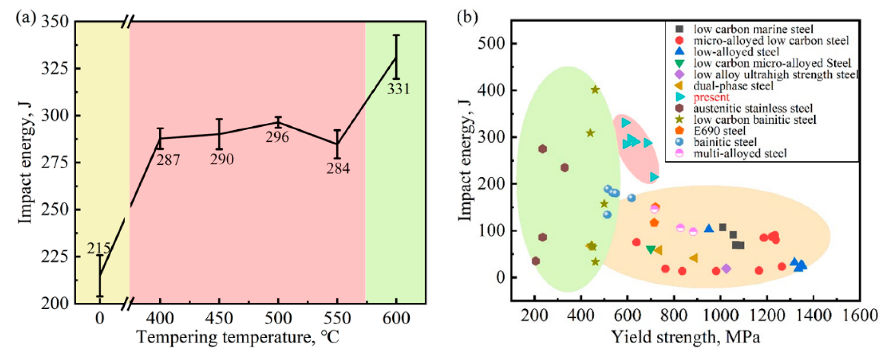
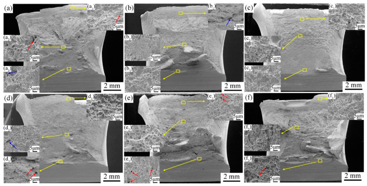
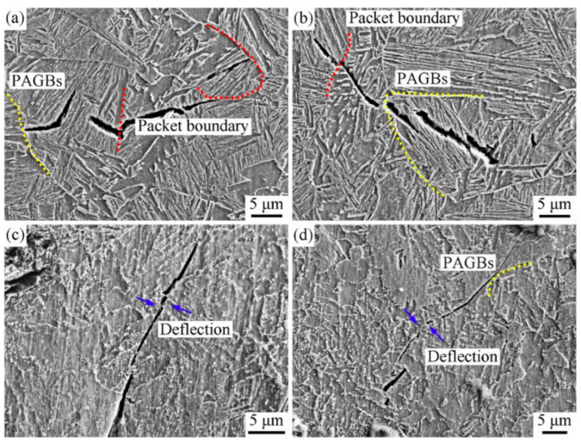
4.3. Impact Fracture Behavior

The mechanism of crack initiation and propagation is depicted in Figure 10b. During tempering, stress concentration easily occurred at the accumulated dislocation, and the hardness of martensite and ferrite was different. Therefore, the relatively soft matrix in the specimen usually underwent initial plastic deformation under impact loading [42], as shown by the blue arrows in Figure 10b. In addition, large local stress concentration was beneficial to crack nucleation and microvoid formation. Under the applied load, the microvoids were transformed into cracks and continued to propagate [31]. However, the propagation paths of cracks along HAGBs and LAGBs were different [42,43], due to different grain boundary energies [19].
The grain boundary energy mainly resulted from dislocation energy, and the dislocation density was determined by the misorientation angle. Therefore, the relationship between grain boundary energy (γgb) and misorientation angle (θ) can be expressed by Equation (3) [25,44]:
γ g b = E 0 θ ( A   l n θ )
where E0 and A depend on boundary plane orientation. It was clear that the grain boundary energy increased with the increase in the misorientation angle. When the crack attempted to pass through LAGBs, the grain boundary energy was low, and the crack was subjected to lower resistance. Therefore, the crack almost propagated linearly. When the crack encountered HAGBs with large grain boundary energy, the energy consumed during crack propagation increased, and thus the crack changed its propagation direction or stopped propagation (Figure 9) [45].
Further, the impact energy of the specimens was related to the percentage of HAGBs [16,46]. It can be seen in Figure 3 and Figure 8 that the impact energy increased with the increase in the percentage of HAGBs, and the increase in HAGBs caused more crack deflection and favored the improvement of steel toughness [25].

5. Conclusions

In this paper, the effect of quenching and tempering on the mechanical properties and impact fracture behavior of low-carbon low-alloy steel were investigated. The conclusions are as follows:
(1)
The microstructure of martensite can be regulated by changing tempering temperature. With the increase in tempering temperature, the dislocation density between laths gradually decreased, resulting in a reduction in strength. Meanwhile, martensitic laths gradually merged and coarsened, and a greater transformation between HAGBs and LAGBs occurred. The increase in HAGBs enhanced the toughness of the steel, and the impact energy also increased.
(2)
It can be considered that combined with the microstructure and mechanical properties, the optimal strengthening and toughness matching can be achieved at 600 °C tempering. The microstructure was mainly composed of tempered martensite, and the yield strength, the tensile strength and the impact energy were 557 MPa, 614 MPa and 331 J, respectively.
(3)
The transformation between LAGBs and LAGBs during tempering also affected the crack propagation. HAGBs effectively deflected and even stopped crack propagation, whereas LAGBs had less influence on crack propagation.

Author Contributions

Investigation, J.Y.; writing—original draft preparation, Y.Z.; writing—review and editing, H.W.; supervision, D.X.; project administration, D.L. and C.T.; funding acquisition, D.X. All authors have read and agreed to the published version of the manuscript.

Funding

This work was funded by Corrosion Resistant Steel and Protection Technology for Marine Building Structure (2021YFB3701700).

Institutional Review Board Statement

Not applicable.

Informed Consent Statement

Not applicable.

Data Availability Statement

Data are contained within the article.

Acknowledgments

Thanks to the Collaborative Innovation Center of Steel Technology of University of Science and Technology Beijing for training and educating. Thanks to my teacher Wu Huibin for his careful guidance. Thanks to the funding of Corrosion Resistant Steel and Protection Technology for Marine Building Structure (2021YFB3701700).

Conflicts of Interest

The authors declare no conflict of interest.

References

  1. Zhou, Y.; Jia, T.; Zhang, X.; Liu, Z.; Misra, R.D.K. Microstructure and toughness of the CGHAZ of an offshore platform steel. J. Mater. Process. Technol. 2015, 219, 314–320. [Google Scholar] [CrossRef]
  2. Zhou, Y.-L.; Chen, J.; Liu, Z.-Y. Corrosion Behavior of Rusted 550 MPa Grade Offshore Platform Steel. J. Iron Steel Res. Int. 2013, 20, 66–73. [Google Scholar] [CrossRef]
  3. Zhang, H.; Sun, M.; Liu, Y.; Ma, D.; Xu, B.; Huang, M.; Li, D.; Li, Y. Ultrafine-grained dual-phase maraging steel with high strength and excellent cryogenic toughness. Acta Mater. 2021, 211, 116878. [Google Scholar] [CrossRef]
  4. Tervo, H.; Kaijalainen, A.; Pallaspuro, S.; Anttila, S.; Mehtonen, S.; Porter, D.; Kömi, J. Low-temperature toughness properties of 500 MPa offshore steels and their simulated coarse-grained heat-affected zones. Mater. Sci. Eng. A 2020, 773, 138719. [Google Scholar] [CrossRef]
  5. Wei, X.; Cao, X.; Luan, J.H.; Jiao, Z.B.; Liu, C.T.; Zhang, Z.W. Synergy of strengthening and toughening of a Cu-rich precipitate-strengthened steel. Mater. Sci. Eng. A 2022, 832, 142487. [Google Scholar] [CrossRef]
  6. Ning, D.; Dai, C.R.; Wu, J.L.; Wang, Y.D.; Wang, Y.Q.; Jing, Y.; Sun, J. Carbide precipitation and coarsening kinetics in low carbon and low alloy steel during quenching and subsequently tempering. Mater. Charact. 2021, 176, 111111. [Google Scholar] [CrossRef]
  7. Hutchinson, B.; Hagström, J.; Karlsson, O.; Lindell, D.; Tornberg, M.; Lindberg, F.; Thuvander, M. Microstructures and hardness of as-quenched martensites (0.1–0.5%C). Acta Mater. 2011, 59, 5845–5858. [Google Scholar] [CrossRef]
  8. Zhao, N.; Zhao, Q.; He, Y.; Liu, R.; Liu, W.; Zheng, W.; Li, L. Strengthening-toughening mechanism of cost-saving marine steel plate with 1000 MPa yield strength. Mater. Sci. Eng. A 2022, 831, 142280. [Google Scholar] [CrossRef]
  9. Liang, Y.; Long, S.; Xu, P.; Lu, Y.; Jiang, Y.; Liang, Y.; Yang, M. The important role of martensite laths to fracture toughness for the ductile fracture controlled by the strain in EA4T axle steel. Mater. Sci. Eng. A 2017, 695, 154–164. [Google Scholar] [CrossRef]
  10. Inoue, J.; Sadeghi, A.; Koseki, T. Slip band formation at free surface of lath martensite in low carbon steel. Acta Mater. 2019, 165, 129–141. [Google Scholar] [CrossRef]
  11. Chen, J.; Li, C.; Ren, J.; Tu, X.; Chen, L. Strength and toughness of Fe-1.2Mn-0.3Cr-1.4Ni-0.4Mo-C tempered steel plate in three cooling processes. Mater. Sci. Eng. A 2019, 754, 178–189. [Google Scholar] [CrossRef]
  12. Thompson, S.W. Interrelationships between yield strength, low-temperature impact toughness, and microstructure in low-carbon, copper-precipitation-strengthened, high-strength low-alloy plate steels. Mater. Sci. Eng. A 2018, 711, 424–433. [Google Scholar] [CrossRef]
  13. Morsdorf, L.; Emelina, E.; Gault, B.; Herbig, M.; Tasan, C.C. Carbon redistribution in quenched and tempered lath martensite. Acta Mater. 2021, 205, 116521. [Google Scholar] [CrossRef]
  14. Gan, X.; Wan, X.; Zhang, Y.; Wang, H.; Li, G.; Xu, G.; Wu, K. Investigation of characteristic and evolution of fine-grained bainitic microstructure in the coarse-grained heat-affected zone of super-high strength steel for offshore structure. Mater. Charact. 2019, 157, 109893. [Google Scholar] [CrossRef]
  15. Yen, H.; Chiang, M.; Lin, Y.; Chen, D.; Huang, C.; Lin, H. High-Temperature Tempered Martensite Embrittlement in Quenched-and-Tempered Offshore Steels. Metals 2017, 7, 253. [Google Scholar] [CrossRef] [Green Version]
  16. Sun, C.; Fu, P.; Ma, X.; Liu, H.; Du, N.; Cao, Y.; Liu, H.; Li, D. Effect of matrix carbon content and lath martensite microstructures on the tempered precipitates and impact toughness of a medium-carbon low-alloy steel. J. Mater. Res. Technol. 2020, 9, 7701–7710. [Google Scholar] [CrossRef]
  17. Long, S.; Liang, Y.; Jiang, Y.; Liang, Y.; Yang, M.; Yi, Y. Effect of quenching temperature on martensite multi-level microstructures and properties of strength and toughness in 20CrNi2Mo steel. Mater. Sci. Eng. A 2016, 676, 38–47. [Google Scholar] [CrossRef]
  18. Li, C.; Duan, R.; Fu, W.; Gao, H.; Wang, D.; Di, X. Improvement of mechanical properties for low carbon ultra-high strength steel strengthened by Cu-rich multistructured precipitation via modification to bainite. Mater. Sci. Eng. A 2021, 817, 141337. [Google Scholar] [CrossRef]
  19. Zhao, Y.; Tong, X.; Wei, X.H.; Xu, S.S.; Lan, S.; Wang, X.L.; Zhang, Z.W. Effects of microstructure on crack resistance and low-temperature toughness of ultra-low carbon high strength steel. Int. J. Plast. 2019, 116, 203–215. [Google Scholar] [CrossRef]
  20. Mao, G.; Cayron, C.; Cao, R.; Logé, R.; Chen, J. The relationship between low-temperature toughness and secondary crack in low-carbon bainitic weld metals. Mater. Charact. 2018, 145, 516–526. [Google Scholar] [CrossRef]
  21. Yang, G.; Xia, S.L.; Zhang, F.C.; Branco, R.; Long, X.Y.; Li, Y.G.; Li, J.H. Effect of tempering temperature on monotonic and low-cycle fatigue properties of a new low-carbon martensitic steel. Mater. Sci. Eng. A 2021, 826, 141939. [Google Scholar] [CrossRef]
  22. Mote, V.D.; Purushotham, Y.; Dole, B.N. Williamson-Hall analysis in estimation of lattice strain in nanometer-sized ZnO particles. J. Theor. Appl. Phys. 2012, 6, 6. [Google Scholar] [CrossRef] [Green Version]
  23. Li, X.; Wiskel, J.; Henein, H.; Ivey, D.; Omotoso, O. Characterization of Microstructure in High Strength Microalloyed Steels Using Quantitative X-Ray Diffraction. In Proceedings of the Biennial International Pipeline Conference 2008, Calgary, AB, Canada, 29 September–3 October 2008. [Google Scholar] [CrossRef]
  24. Xiong, W.; Song, R.; Huo, W.; Yu, P.; Qin, S.; Liu, Z. Microstructure characteristics and impact fracture mechanisms of Nb and V–Ti micro-alloyed offshore platform steels. Vacuum 2022, 195, 110709. [Google Scholar] [CrossRef]
  25. Ren, J.; Li, C.; Han, Y.; Li, E.; Gao, C.; Qiu, C. Effect of initial martensite and tempered carbide on mechanical properties of 3Cr2MnNiMo mold steel. Mater. Sci. Eng. A 2021, 812, 141080. [Google Scholar] [CrossRef]
  26. Zhu, W.; Cui, J.; Chen, Z.; Feng, Y.; Zhao, Y.; Chen, L. Design and Performance of 690 MPa Grade Low-Carbon Microalloyed Construction Structural Steel with High Strength and Toughness. Acta Metall. Sin. 2021, 57, 340–352. [Google Scholar] [CrossRef]
  27. Ghosh, S.; Miettunen, I.; Somani, M.C.; Kömi, J.; Porter, D. Nanolath martensite-austenite structures engineered through DQ&P processing for developing tough, ultrahigh strength steels. Mater. Today Proc. 2021, 46, 2131–2134. [Google Scholar] [CrossRef]
  28. Wang, J.; Li, W.; Zhu, X.; Zhang, L. Effect of martensite morphology and volume fraction on the low-temperature impact toughness of dual-phase steels. Mater. Sci. Eng. A 2022, 832, 142424. [Google Scholar] [CrossRef]
  29. Kim, J.; Choi, S.; Park, D.; Lee, J. Charpy impact properties of stainless steel weldment in liquefied natural gas pipelines: Effect of low temperatures. Mater. Des. 2015, 65, 914–922. [Google Scholar] [CrossRef]
  30. Im, Y.-R.; Oh, Y.J.; Lee, B.-J.; Hong, J.H.; Lee, H.-C. Effects of carbide precipitation on the strength and Charpy impact properties of low carbon Mn-Ni-Mo bainitic steels. J. Nucl. Mater. 2001, 297, 138–148. [Google Scholar] [CrossRef]
  31. Zhou, Y.; Jia, T.; Zhang, X.; Liu, Z.; Misra, R.D.K. Investigation on tempering of granular bainite in an offshore platform steel. Mater. Sci. Eng. A 2015, 626, 352–361. [Google Scholar] [CrossRef]
  32. Zhou, C.; Ye, Q.; Hu, J.; Zhao, T.; Gao, X.; Wang, Z. Ultra-high-strength multi-alloyed steel with enhanced cryogenic toughness using thermally stable retained austenite. Mater. Sci. Eng. A 2022, 831, 142356. [Google Scholar] [CrossRef]
  33. Jia, J.; Liu, Z.; Li, X.; Du, C.; Li, W. Comparative study on the stress corrosion cracking of a new Ni-advanced high strength steel prepared by TMCP, direct quenching, and quenching & tempering. Mater. Sci. Eng. A 2021, 825, 141854. [Google Scholar] [CrossRef]
  34. Bansal, G.K.; Tripathy, S.; Chandan, A.K.; Rajinikanth, V.; Ghosh, C.; Srivastava, V.C.; Ghosh Chowdhury, S. Influence of quenching strategy on phase transformation and mechanical properties of low alloy steel. Mater. Sci. Eng. A 2021, 826, 141937. [Google Scholar] [CrossRef]
  35. Zhang, Y.; Gu, J.; Han, L. Elemental redistribution and precipitation reactions of 9Cr1.5Mo1CoB(FB2) steel during tempering. Mater. Charact. 2021, 171, 110778. [Google Scholar] [CrossRef]
  36. Morsdorf, L.; Tasan, C.C.; Ponge, D.; Raabe, D. 3D structural and atomic-scale analysis of lath martensite: Effect of the transformation sequence. Acta Mater. 2015, 95, 366–377. [Google Scholar] [CrossRef]
  37. Bouissa, Y.; Bohlooli, N.; Shahriari, D.; Champliaud, H.; Morin, J.; Jahazi, M. FEM modeling and experimental validation of quench-induced distortions of large size steel forgings. J. Manuf. Processes 2020, 58, 592–605. [Google Scholar] [CrossRef]
  38. Chen, K.; Jiang, Z.; Liu, F.; Yu, J.; Li, Y.; Gong, W.; Chen, C. Effect of quenching and tempering temperature on microstructure and tensile properties of microalloyed ultra-high strength suspension spring steel. Mater. Sci. Eng. A 2019, 766, 138272. [Google Scholar] [CrossRef]
  39. Ghassemi-Armaki, H.; Chen, R.P.; Maruyama, K.; Yoshizawa, M.; Igarashi, M. Static recovery of tempered lath martensite microstructures during long-term aging in 9–12% Cr heat resistant steels. Mater. Lett. 2009, 63, 2423–2425. [Google Scholar] [CrossRef]
  40. Zhou, T.; Faleskog, J.; Babu, R.P.; Odqvist, J.; Yu, H.; Hedström, P. Exploring the relationship between the microstructure and strength of fresh and tempered martensite in a maraging stainless steel Fe–15Cr–5Ni. Mater. Sci. Eng. A 2019, 745, 420–428. [Google Scholar] [CrossRef]
  41. Jiang, Z.; Du, J.; Wang, P.; Zheng, J.; Li, D.; Li, Y. Mechanism of Improving the Impact Toughness of SA508-3 Steel Used for Nuclear Power by Pre-Transformation of M-A Islands. Acta Metall. Sin. 2021, 57, 891–902. [Google Scholar] [CrossRef]
  42. Shi, G.; Zhao, H.; Zhang, S.; Wang, Q.; Zhang, F. Microstructural characteristics and impact fracture behaviors of low-carbon vanadium-microalloyed steel with different nitrogen contents. Mater. Sci. Eng. A 2020, 769, 138501. [Google Scholar] [CrossRef]
  43. Xiong, Z.; Liu, S.; Wang, X.; Shang, C.; Li, X.; Misra, R.D.K. The contribution of intragranular acicular ferrite microstructural constituent on impact toughness and impeding crack initiation and propagation in the heat-affected zone (HAZ) of low-carbon steels. Mater. Sci. Eng. A 2015, 636, 117–123. [Google Scholar] [CrossRef]
  44. Rohrer, G.S. Grain boundary energy anisotropy: A review. J. Mater. Sci. 2011, 46, 5881–5895. [Google Scholar] [CrossRef] [Green Version]
  45. Li, J.; Zhang, C.; Jiang, B.; Zhou, L.; Liu, Y. Effect of large-size M23C6-type carbides on the low-temperature toughness of martensitic heat-resistant steels. J. Alloy. Compd. 2016, 685, 248–257. [Google Scholar] [CrossRef]
  46. Wang, X.L.; Wang, Z.Q.; Dong, L.L.; Shang, C.J.; Ma, X.P.; Subramanian, S.V. New insights into the mechanism of cooling rate on the impact toughness of coarse grained heat affected zone from the aspect of variant selection. Mater. Sci. Eng. A 2017, 704, 448–458. [Google Scholar] [CrossRef]
Figure 1. Schematic diagrams of heat treatment.
Metals 12 01087 g001
Figure 2. (a) Engineering stress–strain curves, (b) strength and elongation, (c) hardness of the specimens after different heat treatments.
Metals 12 01087 g002
Figure 3. (a) Impact energy of the specimens after different heat treatments, (b) Mechanical property comparison of the experimental steel and other structural steels, including low carbon marine steel [8], micro-alloyed low carbon steel [24], low-alloyed steel [25], low carbon micro-alloyed steel [26], low alloy ultrahigh strength steel [27], dual-phase steel [28], austenitic stainless steel [29], low carbon bainitic steel [30], E690 steel [14], bainitic steel [31], multi-alloyed steel [32].
Metals 12 01087 g003
Figure 4. SEM micrographs of the specimens after different heat treatments. (a) WQ, (b) QT400, (c) QT450, (d) QT500, (e) QT550, (f) QT600.
Metals 12 01087 g004
Figure 5. TEM micrographs of the specimens after different heat treatments. (a) WQ, (b) QT400, (c) QT450, (d) QT500, (e) QT550, (f) QT600.
Metals 12 01087 g005
Figure 6. (a) XRD patterns, (b) dislocation density of the specimens after different heat treatments.
Metals 12 01087 g006
Figure 7. SEM micrographs of impact specimens after different heat treatments. (a) WQ, (b) QT400, (c) QT450, (d) QT500, (e) QT550, (f) QT600.
Metals 12 01087 g007
Figure 8. Kernel average maps and grain boundary distribution maps of the specimens after different heat treatments. (a,d) WQ, (b,e) QT400, (c,f) QT450, (g,j) QT500, (h,k) QT550, (i,l) QT600.
Metals 12 01087 g008
Figure 9. Surfaces perpendicular to the fracture of the specimens after water-quenching or tempering at 600 °C. (a,b) WQ, (c,d) QT600.
Metals 12 01087 g009
Figure 10. Schematic illustration of (a) microstructural evolution of the specimens after different heat treatments, (b) crack initiation and propagation of the specimens after impact test.
Metals 12 01087 g010
Table 1. Chemical composition of the experimental steel (wt.%).
CSiMnAlCrNbTiNiCuFe
0.080.181.610.030.160.0370.0130.260.2Bal.
Publisher’s Note: MDPI stays neutral with regard to jurisdictional claims in published maps and institutional affiliations.

