Abstract
The principal optimum process parameters for printing Ti5Mo fused tracks and layers were determined. The laser power, scanning speed and hatch distance were varied to study their influence on fused track and layer formation. The morphology, geometry, homogeneity, surface roughness, solidification structure, microstructure and microhardness of the fused tracks and layers were analysed. It was observed that, based on the laser energy density, different fused tracks and layers can be achieved. It is only at a certain critical threshold that optimum process parameters could be obtained. Laser power of 200 W with a corresponding scanning speed of 1.0 m/s at a hatch distance of 80 µm was obtained as the optimum process parameter set. As opposed to previous research by the authors, the Mo powder particles in the current investigation melted completely in the Ti5Mo alloy matrix due to the small Mo powder particle size (1 µm). A 50% offset rescanning strategy also improved the surface quality of the layers. The solidification front is predominantly cellular, and the microhardness values obtained fall within the values reported in the current literature.
1. Introduction
Ti-based alloys have been used extensively for biomedical applications with laudable success because they demonstrate excellent combinations of biomechanical and biochemical properties [1,2]. These properties enhance rapid anchoring of Ti-based implants (osseointegration) resulting in a clinical success rate up to 99% over a period of 10 years [3]. These observations demonstrated the good interaction of Ti-based implants with the host bone tissue. This could be due to the unique properties of Ti, which is the precursor powder in the Ti-based alloys. Titanium is a nontoxic element even when ingested in large quantities [4]. Geetha et al. [5] and Sandu et al. [6] demonstrated the influence of ingestion of Ti by humans of up to 0.8 mg per day, proving that Ti was eliminated without being digested/assimilated. This confirmed that Ti, as the precursor alloy in Ti-based alloy, would not have harmful effects on the human body, but rather promote good interaction with the host bone [4]. However, it was empirically proven that the Ti6Al4V alloy, which is known as the working horse of the Ti-based alloys, has some drawbacks due to alloying elements used in formulating the Ti6Al4V alloy [7]. The aluminium in the Ti6Al4V alloy was reported to cause allergic reactions and the use of vanadium was associated with neurological disorders (such as Alzheimer’s disease) [7]. As a result, there has been a consistent attempt by researchers and industry practitioners to developed new Ti-based alloys with nontoxic elements. Experimental results proved that Be, Al, V, Cr, Mn, Fe, Co, Ni, Cu, Zn and Ag are harmful elements, whereas Ti, Mo, B, Mg, Si, P, Ca, Sr, Zr, Nb, Pd, In, Sn, Ta, Pt and Au are considered biocompatible (nontoxic) elements [8]. As a result, materials scientists have been alloying the nontoxic elements with Ti to produce Ti-based alloys which would not be harmful to the body. Binary Ti-Mo alloys have been the subject of several studies, because Mo is considered as the most preferred β-stabilizing element, since it is able to stabilize the β-phase with a low solute concentration [9]. Being a β-stabilizing element, Mo would widen the β-phase domain of the alloy, leading to production of biomedical devices with a lower elastic modulus as compared to the high elastic modulus of Ti6Al4V (100–120 GPa) [4]. The high elastic modulus of Ti6Al4V leads to incomplete stress transfer between bone and implant, resulting in the stress shielding effect [10]. Stress shielding leads to bone resorption in the interface with the implant and increases the risk of implant failure [11]. Alloying Mo with Ti could help overcome the downsides (toxicity and stress shielding) inherent in Ti6Al4V implants.
Ho et al. [12] were among the first in the 1990s to use the conventional methods of manufacturing (casting) to produce the Ti-Mo alloys for biomedical applications. The authors investigated various compositions, from 6 to 20 wt% Mo, and reported that the Ti with 15 wt% Mo and elastic modulus <80 GPa was best suited for biomedical applications. Lee et al. [13] also investigated Ti-xMo (x = 5, 10, 15 and 20 wt.%) alloy compositions by using an arc-melting vacuum-pressure casting system and observed the lowest elastic modulus at 15 wt.% Mo concentration. The preferred suitability of Ti15Mo alloys for biomedical applications as compared to Ti6Al4V was confirmed by a host of other researchers [14,15,16,17]. The investigation of Chen et al. [18] with Mo composition ranging from 5% to 20% (mass fraction) revealed that Ti 10 wt.% Mo with elastic modulus of 29.8 GPa was the most ideal for biomedical applications. Other researchers [19,20,21] also investigated the suitability of Ti-Mo binary system for biomedical applications with 10 wt.% Mo and reported low elastic moduli (23–40 GPa), no cytotoxicity and preferential properties for biomedical applications as compared to Ti6Al4V. The investigations of Heimann et al. [22] focused on Ti-xMo (x = 1, 5 and 10 wt.%) alloy compositions. The experimental results reveal that 5 wt.% Mo demonstrated the least cavitation erosion and was the best suited for biomedical applications. Sung et al. [14] also investigated the suitability of Ti-xMo with compositions 3, 7, 10 and 15 wt% and reported the lowest elastic modulus (<50 GPa) for 7 wt% Mo. These authors concluded that 7 wt% Mo was preferred for biomedical applications. The work of Kumar and Narayanan [23] and Martins et al. [24] confirmed that the amount of Mo ions released in the Ti-xMo alloys systems were within a safe range. Consequently, the suitability of Ti-xMo alloys for biomedical applications was incorporated into the ASTM F2066 implant material standard [25].
Although the pioneers were able to use the conventional methods (casting, forging, etc.) of manufacturing the Ti-xMo alloys ‘successfully’, Mo is a refractory metal with a high melting point [26]. Therefore, alloying Mo with Ti increases the melting point of the powder making the processing of the material very difficult [27]. As a result, the conventional methods of manufacturing could not be used to produce the alloy without defects, such as porosity, shrinkage and inhomogeneous microstructures [27]. However, laser powder bed fusion (LPBF), a subset of the additive manufacturing technology which is currently considered as a renaissance of the manufacturing industry, could be used to manufacture the Ti-xMo alloys without the above-mentioned defects, due to the layer-wise manufacturing strategy employed by the LPBF process. In addition, the versatility of the LPBF process to produce 3D objects with intricated geometries in one manufacturing cycle, opens the window for producing biomimetic objects which would enhance the geometrical, technical and functional properties of biomedical components [28,29].
The authors have previously demonstrated the possibility of in-situ alloying Ti-xMo (x = 10, 15 wt.%) via LPBF [30,31]. However, since the LPBF process is non-linear, the authors wanted to determine the optimum process parameters to produce Ti-xMo (x = 5 wt.%) alloy and compare the mechanical properties of the alloys Ti-xMo (x = 5, 10, 15 wt.%) in subsequent research, because the literature presents divergent results about the best-suited composition of the Ti-xMo alloys for biomedical applications. To the best of the authors’ knowledge, such comparisons have not yet been done for the Ti-xMo alloys using the LPBF manufacturing process.
Single tracks are the initial units produced during the LPBF process and it is the overlapping of the fused tracks that creates single layers. Subsequently, the superposition of the single layers creates a 3D structure. Therefore, the properties of LPBF products depend on the quality of the fused tracks and layers. It is generally accepted that laser power and scanning speed, which have a decisive effect on the quality of the fused tracks, and hatch distance, which influences the quality of the layers, are the principal process parameters [32]. Consequently, the current research seeks to determine the optimum principal process parameters (laser power, scanning speed and hatch distance) that could be used to produce Ti5Mo alloy fused tracks and layers, which could be used to produce the Ti5Mo 3D structures in subsequent investigations. Approximating the laser melting process of building a 3D object to single fused tracks and layers might be a concern, since heat accumulation during thermal recycling of multiply layers enlarge melt pools and increase maximum temperatures [33]. However, literature demonstrated that only single fused tracks alone [32,34,35] have been used as representative of the full LPBF process to investigate the physics of the LPBF process. The current research adopted the same approach of using single fused tracks and layers to obtain optimum process parameters that could be used to produce Ti5Mo 3D structures in subsequent investigations.
2. Materials and Methods
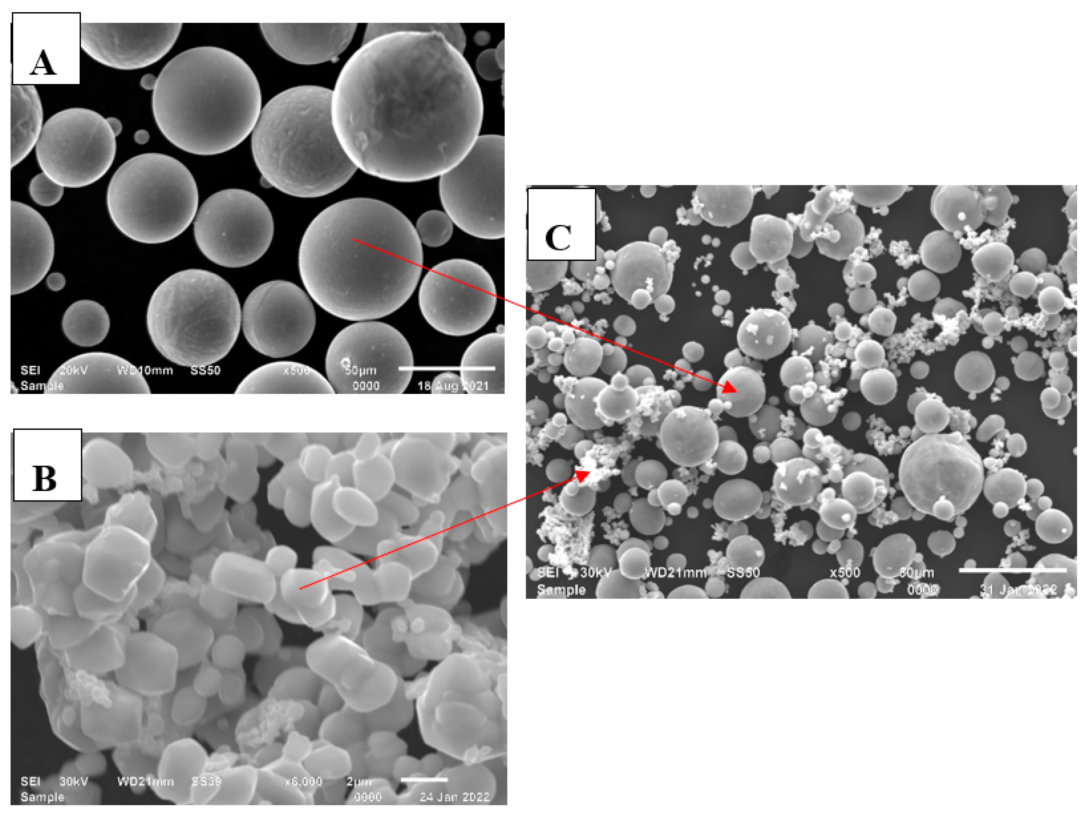
The samples were produced using gas-atomised Ti (Cp Ti, grade 2) powder and Mo powder procured from Sabinano (Pty) Ltd, Johannesburg, South Africa. The nominal chemical composition of the Cp Ti powder as received was: Ti (bal.), O (0.17), Fe (0.062), C (0.006), H (0.002) and N (0.012) in weight percent (wt.%), and the particle size distribution in sieve diameters weight by volume were: d10 = 12.6 μm, d50 = 29.8 μm and d90 = 41.5 μm. The Ti powder particles had high sphericity and smooth surfaces, whereas the Mo powder particles were plate-like with smooth surfaces (Figure 1). The LPBF feedstock was obtained by mechanically mixing 95 wt.% of Ti with 5 wt.% of Mo, referred to as Ti5Mo. A 3D Turbula®-like mixer procured from SSP Processing Equipment (Pty) Ltd., Johannesburg, South Africa was used to mix the Ti and Mo powder blend for 30 min at 150 rpm.
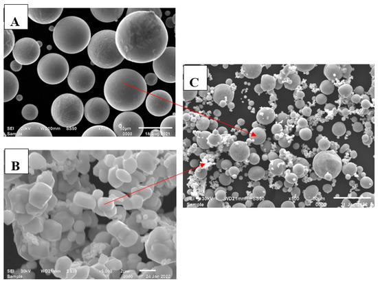
Figure 1.
SEM images of the powders: (A) Cp Ti powder, (B) Mo powder, and (C) Ti5Mo powder blend.
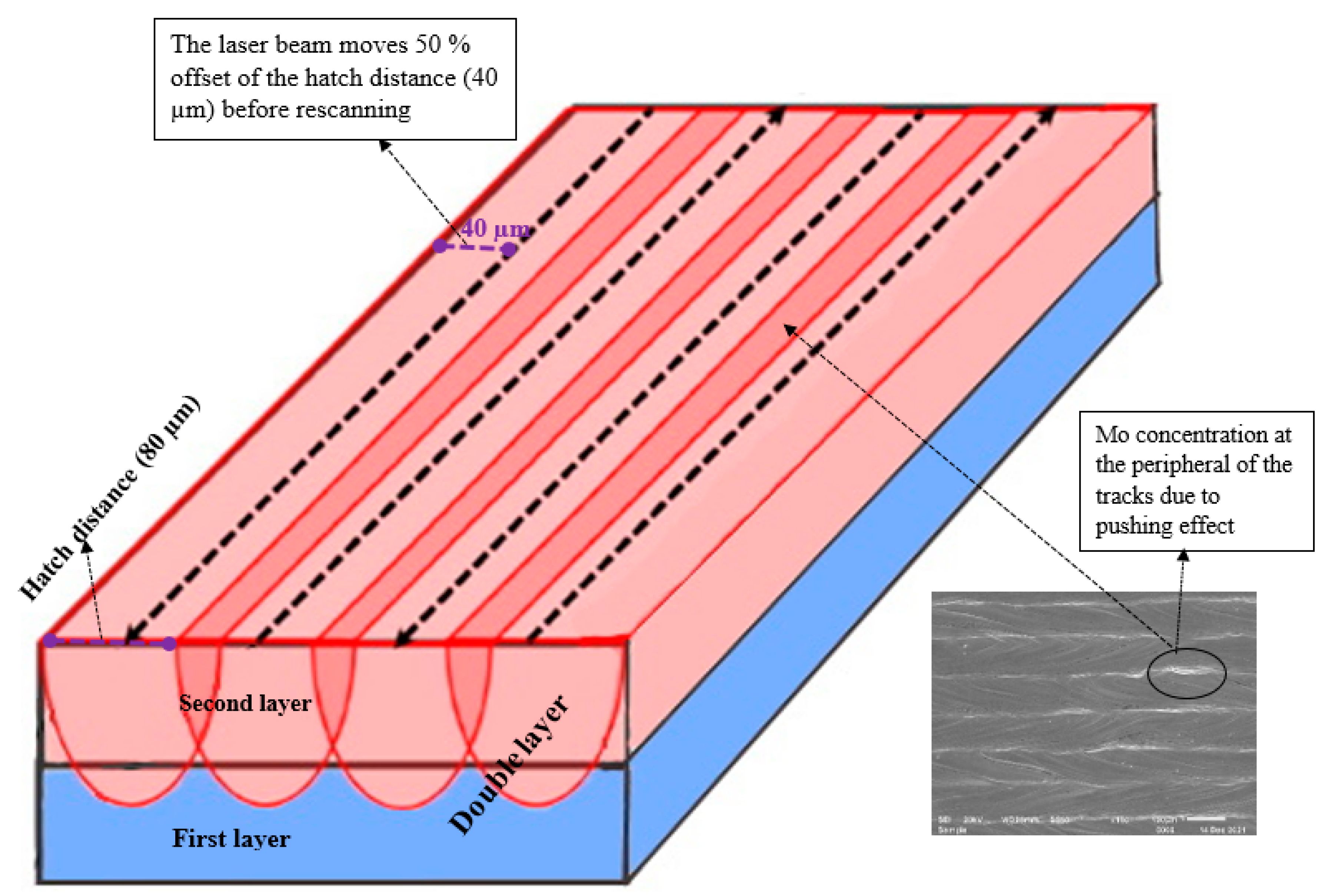
An Electro-Optical Systems (EOS) direct metal laser sintering (DMLS) machine (EOSINT M280) supplied by EOS GmBH, Munich, Germany was used for the studies. The machine is equipped with a continuous-wave ytterbium fibre laser operating at 400 watt. The laser beam had a TEM00 Gaussian profile of 80 µm spot size. Argon was used as the inert gas (protective atmosphere) in the build chamber. A Cp Ti plate was used as the substrate and the chemical composition of the substrate was the same as the chemical composition of the Ti powder used for the experiments. Fused single tracks were produced over a wide range of laser powers (50–350 W) and scanning speeds (0.08–3.4 m/s). For each combination of the process parameters, three single tracks were produced. The tracks were 10 mm in length and the optimum process parameters obtained from fused track analysis were used to produce double layers. These layers were produced at hatch distances of 80 µm, 90 µm and 100 µm and rescanned at a 50% offset hatch distance. (Thus, for the 80 µm hatch distance, the laser moves 40 µm before rescanning, and for 90 µm and 100 µm, it moves 45 µm and 50 µm, respectively, before rescanning—Figure 2).

Figure 2.
A schematic representation of the rescanning strategy.
The top and cross-sectional views of the sintered tracks and layers were analysed using optical and scanning electron microscopy supplied by Carl Zeiss AG, Oberkochen, Germany. The cross-sections of the samples were subjected to standard Struers metallurgical preparation procedures (grinding with 320 papers, polishing by diamond suspensions of 9 µm, 3 µm and 1 µm size [36]) and etched with Kroll’s reagent). The reagent was supplied by Advanced Solution, Johannesburg, South Africa. The cross-sections of the fused tracks were geometrically analysed by measuring the width of the track (W), height of the track (H) and penetration depth (D) as demonstrated elsewhere [35,37]. The surface roughness (Rz) of the samples was measured using a Surftest SJ-210 portable surface roughness meter supplied by Mitutoyo, Tokyo, Japan. The microhardness of the samples was measured with a FM-700 Digital Vickers Microhardness Tester at a constant load of 200 g for 15 s. The a FM-700 Digital was purchased from Future-Tech-Corp, Kanagawa, Japan. Thirty (30) measurements were taken on the polished cross-sections of the samples perpendicular to the building direction, for statistical purposes.
3. Results and Discussion
3.1. Geometry and Morphology of the Fused Single Tracks
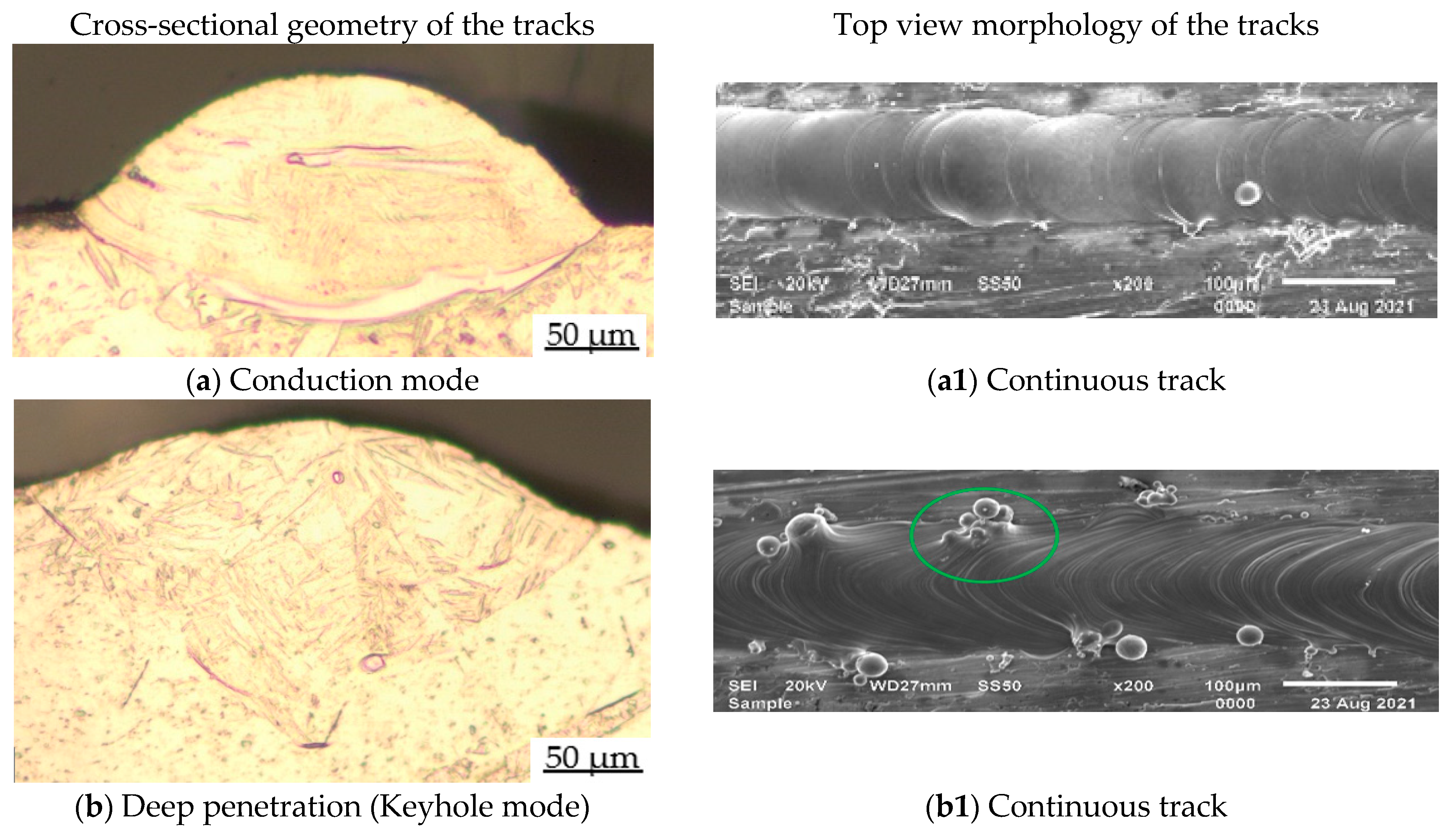
The LPBF process is a very complex process of manufacturing a 3D object. It is a multidisciplinary manufacturing process based on laser physics, optics, heat and mass transfer, mechanics, metallurgy, etc. The process is closely related to the laser welding process, which has been studied extensively in the literature [38]; hence, laser welding theories are normally used to explain the LPBF phenomenon [39]. Just as in laser welding, there are two main modes of laser radiation when the laser beam impinges on the powder bed, which are the conduction mode and the keyhole mode [40]. When the laser beam impinges on the powder bed the laser energy is absorbed by the skin of the upper powder particles. The powder particles at the top begin to melt and the heat is transmitted to the remaining powder particles until a molten pool is formed. Depending on the laser energy density (laser power(P)/scanning speed(V)) of the laser beam [33], a conduction mode profile or keyhole mode profile of the melting process can be formed. A conduction mode is achieved when the thermal transport is mediated mainly via conduction and convection within the molten pool (Figure 3a) [41].


Figure 3.
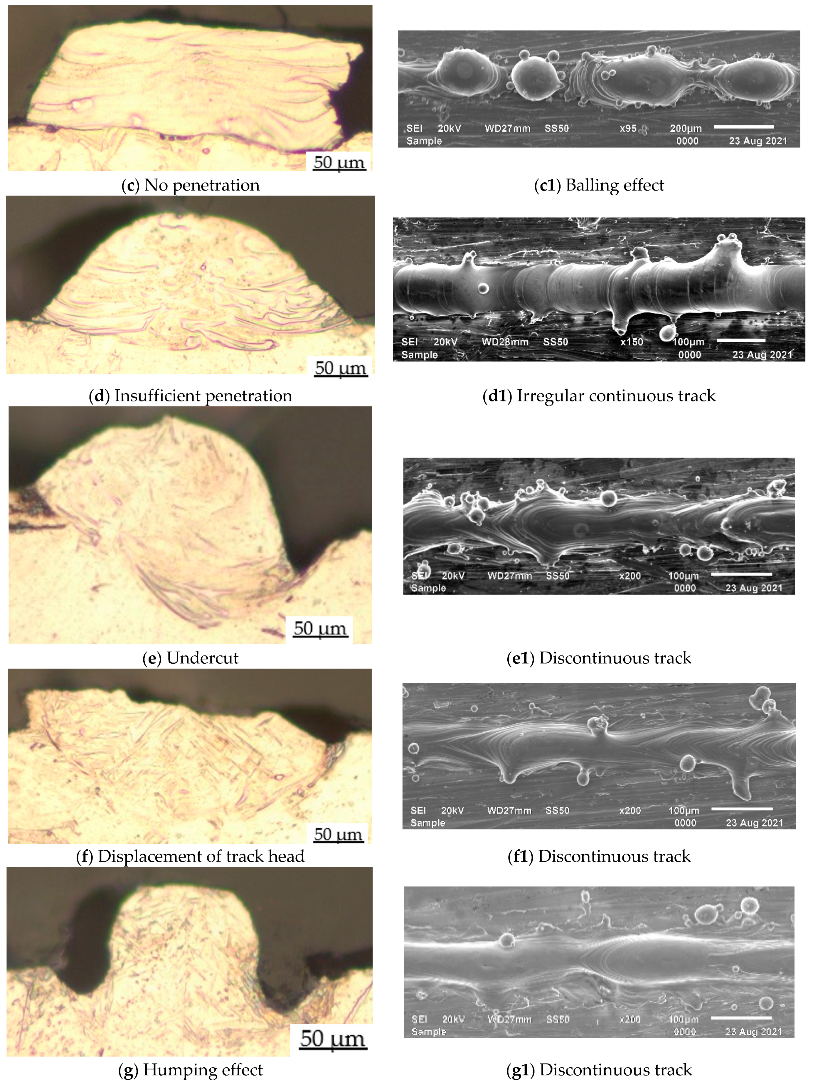
Geometry and morphology of the fused powder tracks at various process parameters, (a) conduction mode: 200 W, 1.0 m/s; (b) deep penetration: 350 W, 1.2 m/s; (c) no penetration: 50 W, 0.4 m/s; (d) insufficient penetration: 150 W, 1.0 m/s; (e) undercut: 300 W, 2.2 m/s; (f) displacement of track head: 350 W, 2.6 m/s; (g) humping effect: 100 W, 1.0 m/s. (a1) Continuous track: 200 W, 1.0 m/s; (b1) Continuous track: 350 W, 1.2 m/s; (c1) Balling effect: 50 W, 0.4 m/s; (d1) Irregular continuous track: 150 W, 1.0 m/s (e1) Discontinuous track: 300 W, 2.2 m/s (f1) Discontinuous track: 350 W, 2.6 m/s; (g1) Discontinuous track: 100 W, 1.0 m/s.
However, if the laser energy density exceeds certain criteria, the mode of melting could change from conduction mode to keyhole mode (Figure 3b) [37]. Thus, there is a threshold for the combination of the process parameters that determines the laser energy density (P/V) which influences the geometrical characteristics and the morphology of the fused tracks.
From Figure 3 and Figure 4, it could be seen that the laser-matter interaction could result in other melting features, such as no penetration, insufficient penetration and defects (undercut, displacement, humping effect etc.). No penetration or insufficient penetration occurs when the laser energy density is not enough to melt the powder particles and penetrate the substrate (previously solidified layers) [32]. As observed from Figure 3c,d of the current study, the laser energy density was sufficient to melt the Ti5Mo powder completely but could not penetrate the substrate or penetrate the substrate sufficiently. The laser interaction with the Ti5Mo powder bed also presents other forms of laser melting profiles (Figure 3e–g). These variations in the geometry of the fused tracks are due to the hydrodynamic movement of the molten pool which is greatly influenced by the Gaussian laser beam [42]. The Gaussian laser beam that melts the constituent powder has spatial intensity distribution. As a result, the laser intensity at the centre of the molten pool is higher than at the periphery of the cylindrical molten pool. The non-uniform distribution of the laser intensity creates a temperature gradient in the molten pool. From the temperature gradient, differences in surface tension between the centre and the edge of the molten pool arise. The surface tension induces recirculation of the molten pool (Marangoni effect) [33], resulting in different track geometry as the molten liquid solidifies. Kou et al., [43] also reported that the non-uniform temperature fields across the molten pool could induce waves in the molten pool. The waves would cause deformation of the molten track geometry as the molten pool solidifies. Qiu et al. [44] reported that the complex melt flow governed by several operating parameters (laser beam absorption, viscosity, surface tension, capillary effects, gravity, etc.) caused the cylindrical molten pool to move in a dispersed and random manner provoking molten pool surface oscillation and ripple formation, which could lead to the deformation of the tracks. As a result, as presented in Figure 3e–g, the sintered tracks demonstrated different types of deformation due to the spatial intensity distribution of the Gaussian laser beam. King et al. [41] and Khairallah et al. [33] noted that Rayleigh capillary and thermocapillary instabilities have a significant effect on the LPBF process. According to the Plateau–Rayleigh instabilities theory, a cylindrical molten pool would be unstable if its ratio of length L to its diameter W exceeds unity π. Thus, a thermocapillary liquid with a high aspect ratio would break down to lower its surface energy. The Plateau–Rayleigh effect pushes the molten pool upwards by fluid flow and shrinks by surface tension (Marangoni effect) [43]. The upward pushing of the molten pool and the shrinkage due to the surface gradient could lead to deformation of the tracks, forming undercuts (Figure 3e), displacement of the track head (Figure 3f) and the humping effect (Figure 3g). The Marangoni effect and the thermocapillary instability are surface tension phenomena that influence the fluid flow from regions of lower surface tension to regions of higher surface tension and can be expressed as in Equation (1) [33].
where Ma is the Marangoni number, is the surface tension gradient, is the temperature gradient, L is the length of the melt pool, ƞ is the viscosity and α is the thermal diffusivity.
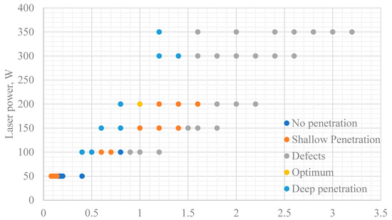
Figure 4.
Classification of the laser penetration profiles.
If the surface tension gradient is negative, a shallow and broad molten pool of large liquid phase (large surface curvature) is formed, but if the surface tension gradient is positive, a deep narrow melt pool would be formed. The surface tension for most alloys including Ti-Mo alloys was reported to be negative [45]. It is, therefore, expected that the Ti5Mo melt pool would form a shallow and broad cylindrical melt pool with high surface energy. Due to the recirculation in the molten pool, the broad liquid curvature surface would break down (deform) to lower its surface energy. The tracks (Figure 3e–g) deform to lower their surface energy per Lord Rayleigh–Plateau [46] instabilities theory of thermocapillary flow. As can be observed (Figure 3), the instability (deformation) of the molten pool increases with increasing scanning speed and laser power. The simulation report of Khairallah et al. [33] demonstrated that the deformation of the melt pool was dependent on the operating temperature within the molten pool. According to Fischer et al. [47], the operating temperature in the molten pool could be estimated as [47]:
A high laser power produces a high E (higher laser energy density), which causes the operating temperature of the molten pool to increase. A higher operating temperature amplifies the recirculation waves within the molten pool, leading to a higher stochastic melt flow. The high turbulence within the molten pool would result in the deformation of the tracks with increasing laser beam energy (E). As a result, the deformation of the tracks increased with increasing laser power (Figure 4).
Also, the fast-advancing laser beam (high scanning speeds) have a high tendency of splashing the molten pool. As observed in nature, as boats move through water, bow waves develop in front of the motion [48]. The fast-advancing laser beam splashes the molten pool (bow wave) and due to the inherent high rate of melting and cooling of the LPBF process, the splash rapidly solidifies to form a deformed geometry. For the current experiments, the deformation of the tracks seemed to increase with increasing scanning speed and laser power (Figure 4).
The conduction mode (Figure 3a) and keyhole mode (Figure 3b) tracks have been the focus of many researchers, probably due to the unique mechanical properties they could provide. The two groups of laser melting modes have their own superiority and inferiority. The advantages of the keyhole mode are that it is characterized by a large penetration depth, small heat-affected zone and high-energy efficiency. These have always attracted more industrial applications in the field of laser welding as compared to the conduction mode profile [49]. The main advantages of the conduction mode are high-process stability and more accurate control of the heat input to the base material as compared to the keyhole mode [50]. Due to the different melting depth and thermal recycling associated with the two laser sintering processes, the microstructure and mechanical properties of samples produced by the two modes are entirely different [51]. Yang et al. [50] used the two modes to produce Ti6Al4V samples and reported that the keyhole mode samples demonstrated poorer formability, but better ductility; conversely, the conduction mode samples demonstrated more outstanding formability but worse ductility. As presented in Figure 3, only samples produced at laser power 200 W at a corresponding scanning speed of 1.0 m/s demonstrated conduction mode. Keyhole mode profiles were present at all laser powers (50–350 W) at relatively lower scanning speeds (Figure 3).
As mentioned earlier, keyhole modes are formed when the energy density is high enough to melt the Ti5Mo powder and drill into the previously solidified layers. The deep melting could cause the Ti5Mo powder particles to vaporize in some local regions within the molten pool. The dense vapour plume, consisting of a cluster of atoms, ions and electrons, produces a recoil momentum on the molten material to form a cavity. Due to the rapid hydrodynamic movement of the thermocapillary melt flow, coupled with the rapid solidification rate, the vapour may not be able to escape before the solidification, but rather be entrapped in the solidified molten pool, resulting in defects in the final 3D parts [41]. Due to the deep penetration into the substrate, the keyhole mode melting resembles a V-shape profile, whereas conduction mode melting resembles a U-shape profile, since there is no further deep absorption of the laser energy below the substrate [50]. Although in the current study the keyhole mode profiles were of the V shape, there was no entrapped gas present in the deep penetrations. This might have been due to the thermophysical differences between the constituent powders. The melting point of Mo is higher than the melting point of Ti (Mo = 2623 °C, Ti = 1668 °C) and the density of Mo is higher than the density of Ti (Mo = 10,220 Kgm−3, Ti = 4500 Kgm−3) [52]. In addition, the laser reflectance of Mo is higher than that of Ti [53]. Therefore, during the LPBF process, the Ti would melt first due to its lower melting temperature and Mo would move to the bottom of the molten pool due to its higher density. After the laser energy had melted, the Ti5Mo powder particles and the laser were about to start drilling the substrate when the Mo powder particles reflected most of the laser energy at the bottom of the molten pool and the remaining laser energy could not entrap the vapour in the wake of the laser beam before the rapid solidification.
Apart from the U-shape and V-shape description of the conduction and keyhole mode profiles, there are other boundary conditions that establish the differences between the keyhole mode and the conduction mode. Nakamura et al. [54] stated that a conduction mode is present when half the width (W) of the track equals the penetration depth (D) of the fused track .
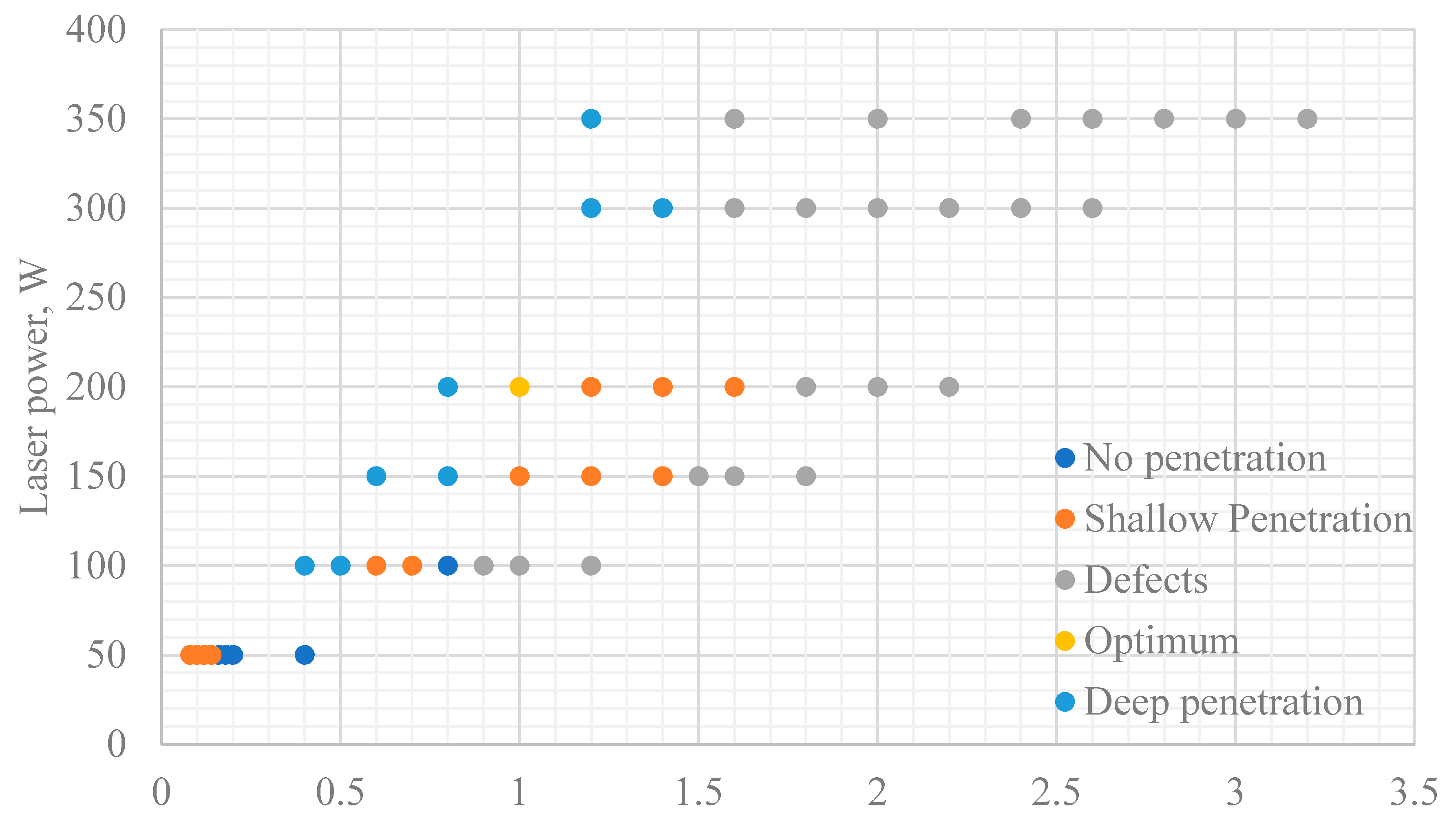
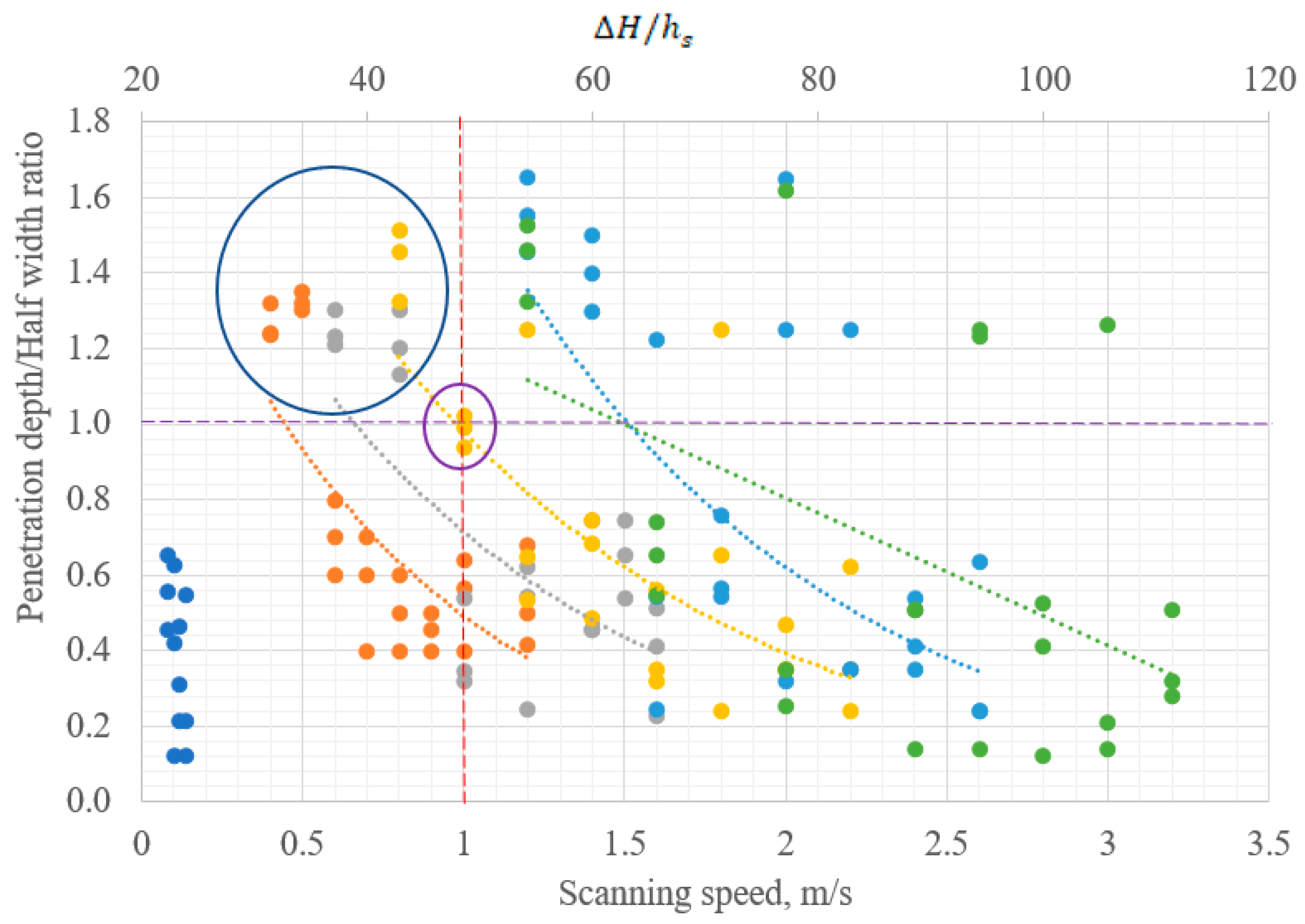
As presented in Figure 5, only laser power of 200 W with a corresponding scanning speed of 1.0 m/s has its ratio of (Figure 5, the purple circle). The combination of all the other process parameters were above or below the purple dotted line at unity (1), demonstrating no penetration, insufficient penetration and deep penetration. The conduction mode process parameters (200 W, 1.0 m/s) could be considered as the preferred optimal process parameters for manufacturing the Ti5Mo powder blend. However, the literature has revealed that moderate penetration keyhole mode could also be considered as optimal for LPBF process [50].

Figure 5.
Ratio of penetration depth in relation to scanning speed and normalised enthalpy.
According to Rai et al. [38], the laser melting process would produce keyhole mode results when
where is the maximum temperature of the molten pool and is the boiling temperature of the material.
The normalized enthalpy model proposed by Hann et al. [39] further expanded Equation (3) in terms of the spatial intensity distribution of the Gaussian laser beam. Hann et al. [39] assumed that the penetration by the Gaussian laser beam was a function only of the ratio of the deposited energy density to the enthalpy at melting (). King et al. [41] made a very impressive derivation that described the transition from one mode to another more perfectly as compared to the initial derivations based on the normalized enthalpy proposed by Hann et al. [39] for laser welding. According to the King et al. [41] derivation, for a Gaussian beam diameter of d, the maximum temperature of the molten pool could be estimated as:
where A is the absorption coefficient of the material, I is laser intensity, d is the laser spot size, k is the thermal conductivity of the molten material, D is thermal diffusivity of the molten material and t is the interaction time between the laser beam and the metal powder. At a selected scanning speed, v, the interaction time between the laser beam and the metal powder could be estimated as
Then, the keyhole threshold in terms of normalized enthalpy could be written as [41]:
From Equation (3), the keyhole mode threshold according to the LPBF process could be written as [41]:
From the detailed analytical presentations of King et al. [41], it could be stated that the threshold for the keyhole mode was directly determined by the applied laser power, scanning speed and beam size diameter. Since the beam size diameter was constant in the current research, laser power and scanning speed were considered as the main determining factors that influenced the molten pool geometries. From Figure 5, the threshold enthalpy for switching from conduction mode to keyhole mode is . Since the constituent powder is made up of 95 wt.% Ti, only the thermophysical properties of Ti (Table 1) were used for the enthalpy calculations.

Table 1.
Thermophysical properties of titanium.
Any value above the threshold value would produce a keyhole profile and values below would produce insufficient or no penetration. However, there were values below the threshold value that demonstrated keyhole characteristics (Figure 5, the blue circle). This could be due to the fact that the normalised enthalpy theory scaling is lacking some physics and fails to account for the additional physics that exist in the keyhole formation process, as explained by King et al. [41].
It could be observed that the ratio of penetration depth to half-width decreased with increasing scanning speed (Figure 5). The decrease in the enthalpy (linear energy density—Figure 6) with increasing scanning speed resulted in the decrease of the depth of penetration with increasing scanning speeds. As the scanning speed increased, the laser energy input of the molten pool decreased (Figure 6). The low molten pool operating temperature was not sufficient to melt the Ti5Mo powder and drill into the substrate. As a result, the depth of penetration as ratio of half-width decreased with increasing scanning speed (Figure 5). Additionally, the time of radiation of the powder bed decreased with increasing scanning speed. The short dwelling time of the laser beam on the powder bed could lead to a reduction in the absorption of the laser energy at a particular spot on the powder bed. As a result, the depth of welding of the new layer into the previous layer (substrate) reduced with increasing scanning speeds at the same laser power as shown in Figure 5.

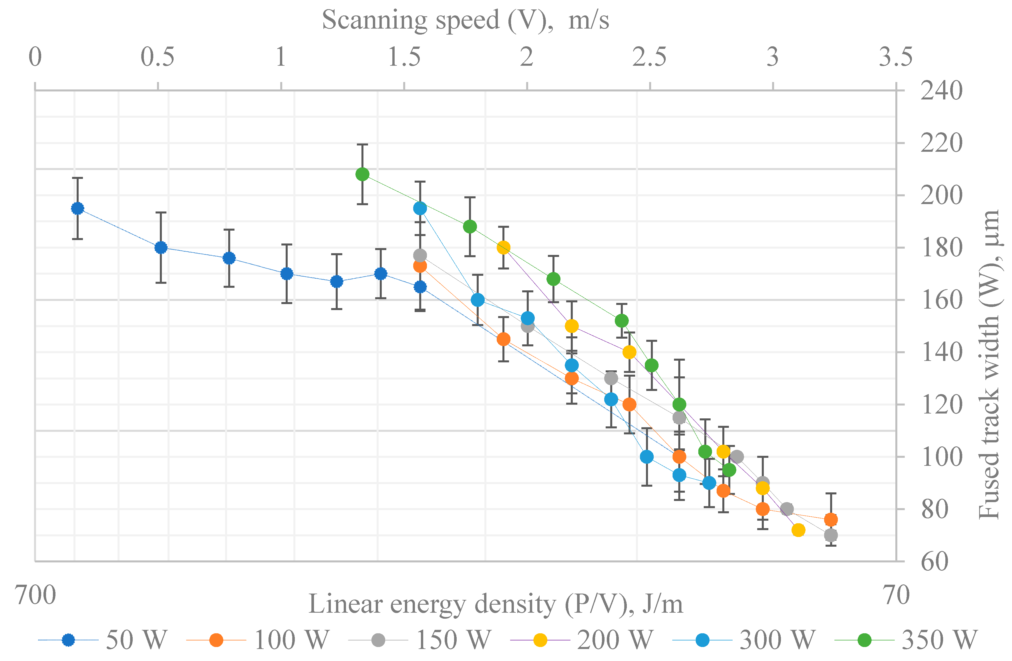
Figure 6.
Relationship between linear energy density, scanning speeds and width of the tracks.
The effect of the laser power on the width of the fused tracks at the various scanning speeds was also investigated. Such investigations would enable the selection of the appropriate hatch distance for manufacturing a 3D object. The results revealed that the width of the fused tracks also reduced with increasing scanning speeds because the laser energy density reduced with increasing scanning speeds (Figure 6). As the linear energy decreased, the temperature in the molten pool decreased. The low fusing temperature led to a viscous melt flow with a small liquid phase. As a result, the curvature of the cylindrical molten pool reduced, leading to a reduction in the widths of the fused tracks with increasing scanning speeds as shown in Figure 6.
3.2. Formation of Spatter Particles on the Fused Tracks
Spatter particles, also known as satellites, were observed at the surfaces and edges of the fused tracks (Figure 3b1, the green circle). During the LPBF process, spatter particles may be formed by two main mechanisms: melt spattering and partial powder melting in the peripheral zone of the laser spot. Melt spattering occurs when the molten liquid is separated and splashes ahead of the advancing laser beam and is pinched off onto the powder bed. Due to the rapid rate of solidification during the melting process, the splashing molten liquid solidifies on the surfaces of the fused tracks as spatter particles. From Equation (2), the molten pool temperature increases with increasing laser power. At a higher laser power, the recirculation of the molten pool also increases. The amplified waves on the surface of the molten pool have a higher probability of ejecting liquid particles onto the powder bed. As a result, spatter particles on the surfaces of the fused tracks produced in the current experimentation increased with increasing laser power (Figure 3. Track a1 was produced at 200 W and it had fewer spatter particles as compared to track b1 produced at 350 W).
3.3. Analysis of Ti5Mo Layers
It is the line-by-line arrangement of the sintered tracks that would lead to the production of a layer. To obtain a 3D object with good mechanical integrity, there is a need to determine the appropriate hatch distance that should be placed in between adjacent sintered tracks. For the current experiment, layers were produced at three different hatch distances of 80 µm, 90 µm and 100 µm with the conduction mode optimal process parameters (200 W, 1.0 m/s) obtained from the sintered tracks analysis. The hatch distances were selected based on Yadroitsev et al. [32] hierarchical principles of printing a 3D object. Yadroitsev et al. [32] stated that the hatch distance should not be less than the average width of the sintered tracks to ensure sufficient overlapping between neighbouring tracks. From Figure 5, it could be seen that the width of the sintered tracks ranges between 70–210. Hence, it is logical and convincing to experiment with the selected hatch distances in order to select the most suitable option to produce a 3D object.
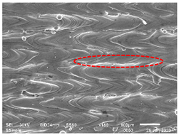
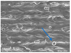
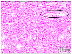
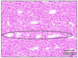
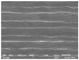
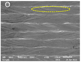
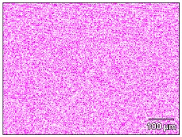
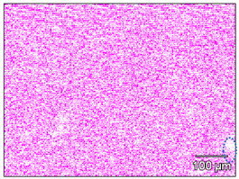
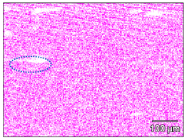
From Table 2, it could be observed that at all the selected hatch distances, the sintered tracks overlapped with wavy-like patterns due to recirculation of the molten pool [37]. Satellites were present at the surface of the layers (Table 2, single scan—the blue arrow). The number of satellites seems to increase with increasing hatch distance. A fewer number of satellites were present on the surface of the layers produced at 80 µm hatch distance. This is due to the large overlapping of tracks produced at 80 µm compared to the other hatch distances. The solidified molten pool reveals that pockets of Mo concentrations were present at the periphery of the sintered layers (Table 2, the red and the black dotted circles). This could be the result of the pushing effect [56]. Due to the thermophysical differences between the two elemental powders (the higher density of Mo as compared to Ti), the rate of motion of the solidification front of the molten pool is faster than the motion of Mo powder particles in the molten pool. The slow-moving Mo powder particles were captured in the solidification front and were pushed to the peripheral of the sintered tracks. Due to the fast-cooling rate of the LPBF process [33] Mo at the borders of the sintered tracks could not mix homogenously with the molten pool before the molten liquid solidifies. As a result, pockets of Mo concentration could be seen at the periphery of the sintered tracks.
Table 2.
Surface morphology and Mo distribution map by EDS of the Ti5Mo double layers with different scanning strategies and hatch distances.
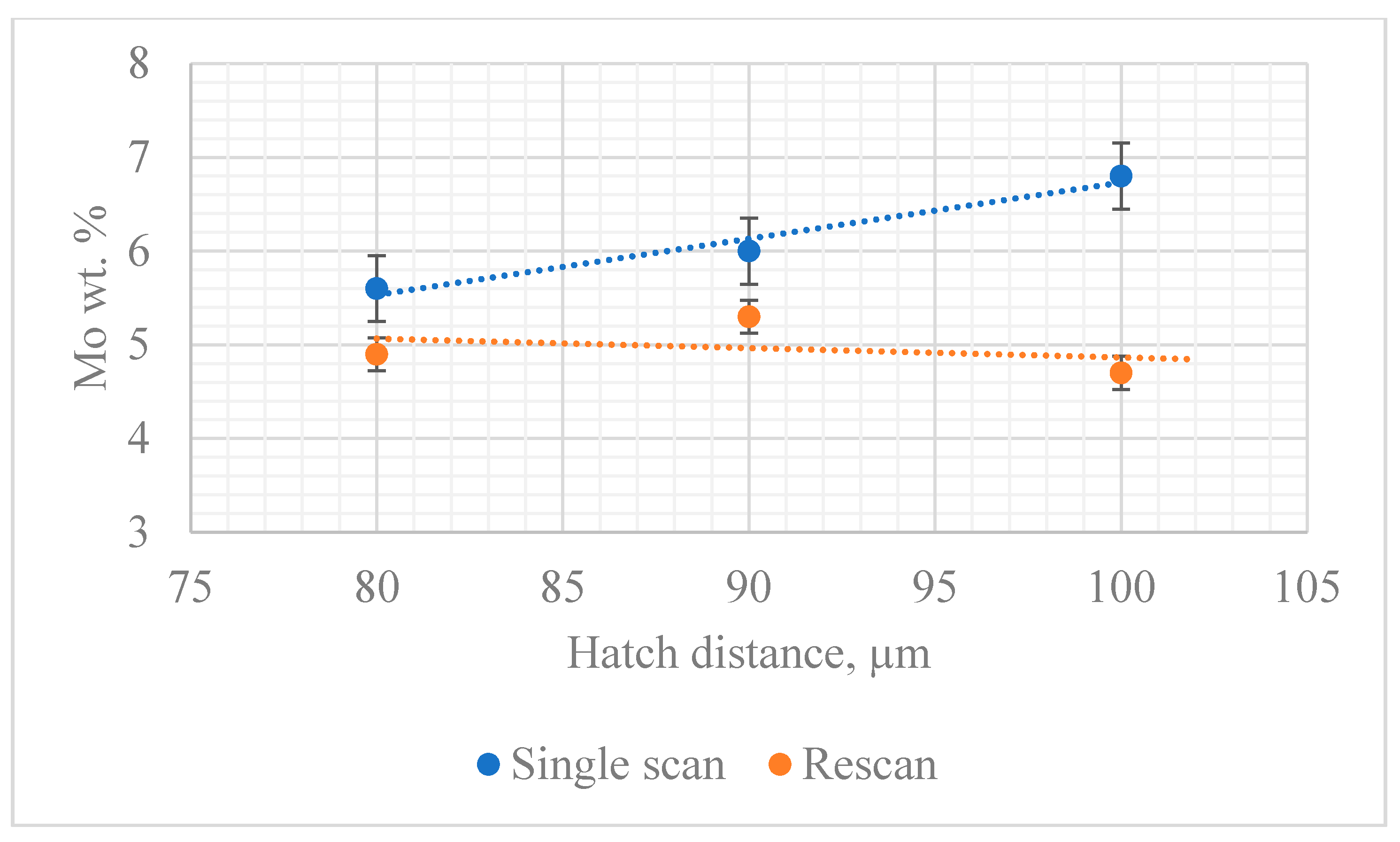
To improve the surface quality of the layers, a rescanning strategy was employed (Figure 2). The samples were rescanned at a 50% offset of the hatch distances. Thus, for the 80 µm hatch distances layer, the laser beam shifted 40 µm in the plane of the laser beam; for 90 µm, the laser beam shifted 45 µm and 50 µm for the 100 µm hatch distance. The rescanning strategy of 50% offset would ensure that all the Mo concentration at the boarders of the sintered tracks could be homogenised with the bulk material. The rescanning strategy removes almost all satellites from the surface of the layers and improves on the homogeneity of the Ti5Mo alloy matrix (Table 2, rescan samples). However, there isstill Mo concentration at the edges of the tracks after the rescanning (Table 2, the yellow and the blue dotted lines). The average wt.% (Figure 7) distribution of Mo in the Ti5Mo alloy matrix attest to the improvement in the homogeneity in the alloy due to the unique rescanning strategy employed.

Figure 7.
Average Wt.% distribution of Mo in the Ti5Mo alloy matrix at different hatch distances.
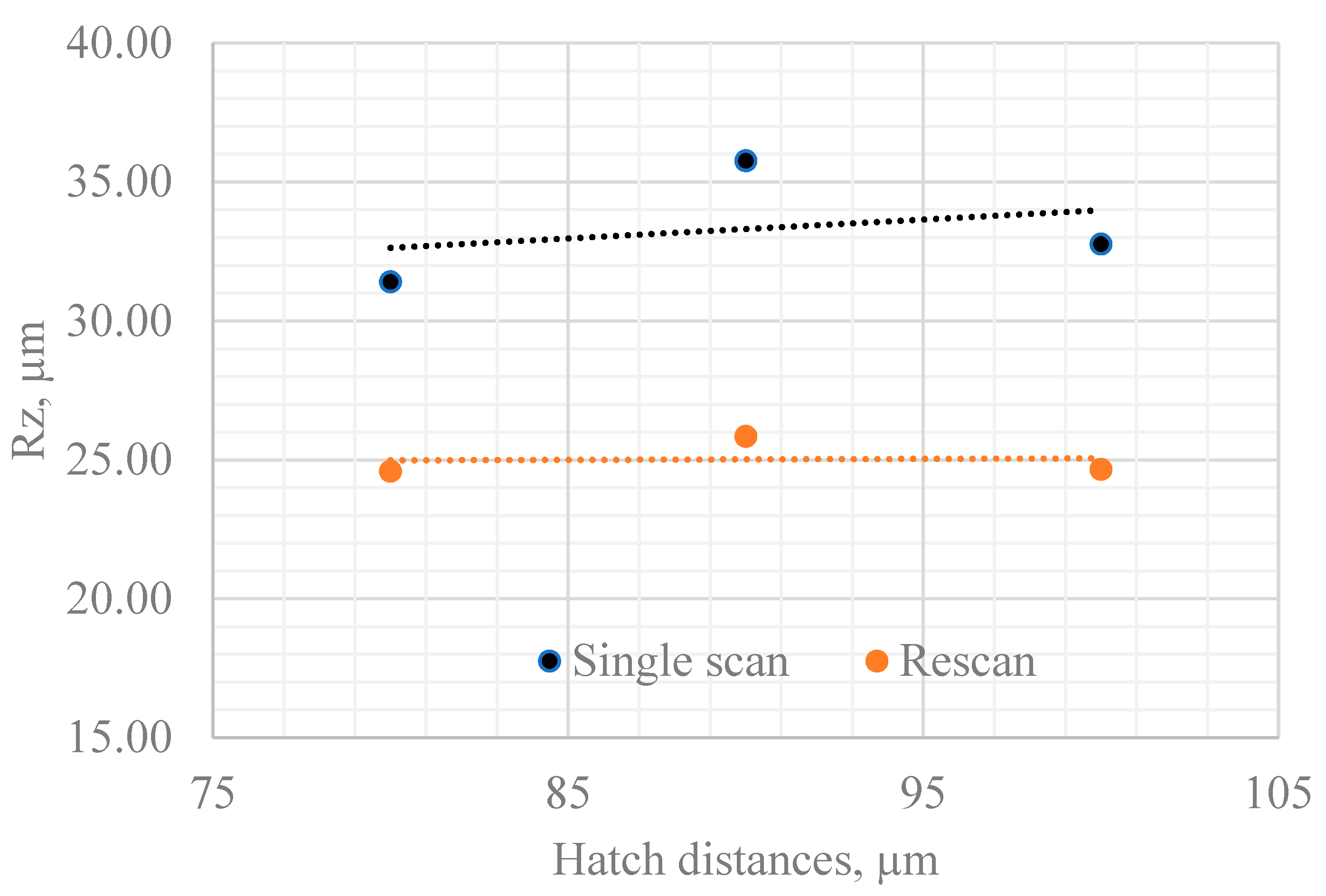
There is almost 50% improvement on the surface quality (surface roughness) of the samples after the rescanning strategy was employed (Figure 8). The improvement on the surface quality of the Ti5Mo layers after the second exposure of the powder bed would enhance the agility of adopting of LPBF processes for most industries. It is well known that surface roughness is one main drawbacks of the LPBF process. Using the current rescanning strategy to improve the surface quality of LPBF products would certainly enhance the widespread industrial application of the LPBF process.

Figure 8.
Surface roughness (Rz) of the sintered layers.
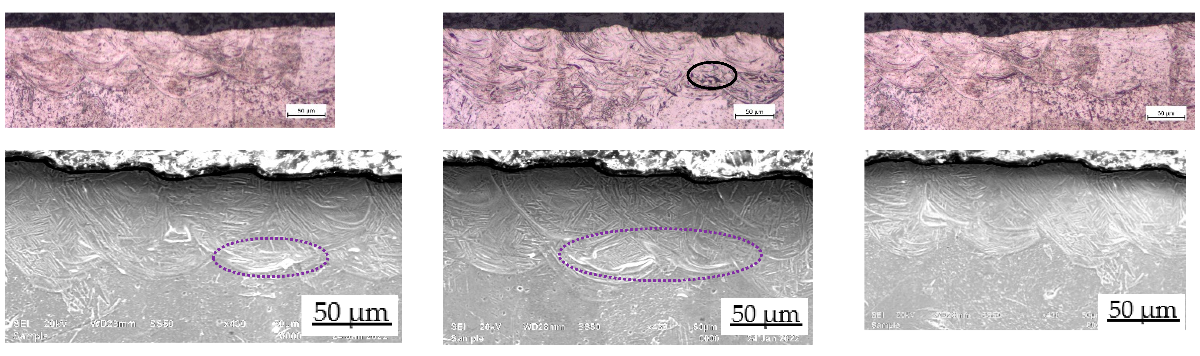
From the cross-sectional observation, there is not much difference between the single scan and the rescan. Hence, only the double scan results were presented (Figure 9, cross-sectional view). Just as observed from the top surface, pockets of Mo concentration were observed from the cross-sectional view of the layers (Figure 9, cross-sectional view—the black and the purple dotted circles). The pockets of Mo-rich areas were distributed randomly in the Ti5Mo alloy matrix. The dispersed distribution of Mo is due to the Marangoni convective flow within the molten pool. This observation indicated that in-situ alloying of elemental powders to print 3D objects has not yet attained maturity and further research is required to be able to print complete homogenous 3D structures via in-situ alloying.

Figure 9.
Optical and secondary electron images of the Ti5Mo cross-sectional view.
3.4. Solidification Structure and Microstructure
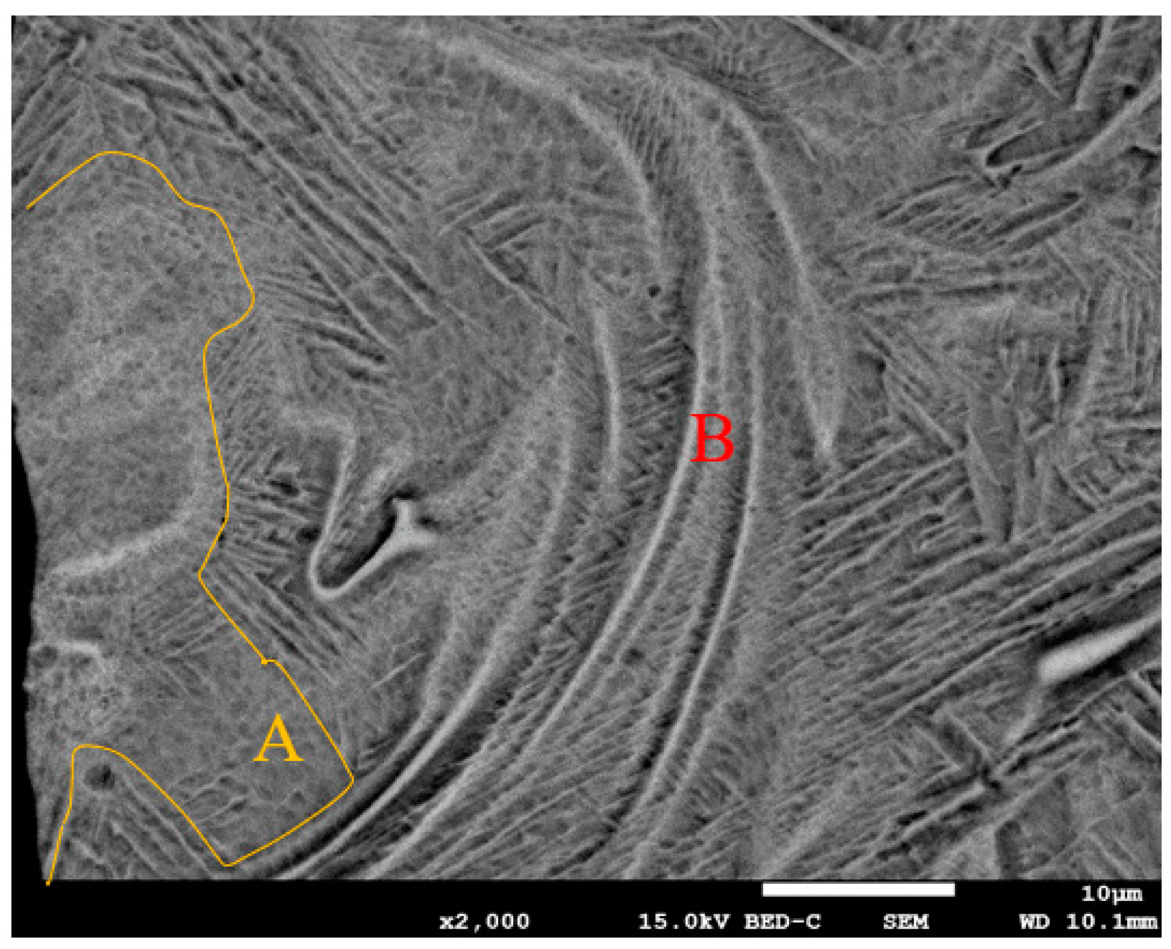
The molten structure is predominately cellular (Figure 10. Area B). This is expected because alloys do not solidify in a planar mode due to solute redistribution resulting in constitutional undercooling that destabilise the solidification front. There appears to be a region of planar mode (Figure 10. Area A). This is possible because as the laser traverses the powder bed and begins to melt the powder, the Mo concentration gradients at the liquid-solid interface of the Ti5Mo molten pool are still increasing and have not reached a steady state. At a low solute concentration of Mo in the Ti5Mo molten pool, the critical thermal gradient for planar solidification is low and a planar front is stable. As a result, there are regions of planar solidification front in the solidified structure. As the concentration gradient of Mo in the Ti5Mo alloy molten pool increases, the solidification front changes from planar to cellular mode. Since planar solidification normally occurs in pure metals and is rare for alloys, for the current experiment, the solidification structure is predominantly cellular for the Ti5Mo alloy. The switching between solidification modes during the LPBF process also contributed to the heterogeneous microstructure nature of LPBF as built components before heat treatments [57].

Figure 10.
Solidification structure of the Ti5Mo alloy.
The microstructure of the Ti5Mo layers (Figure 11) is constituted with α and β phases showing as dark-grey varying contrast, acicular martensite and pockets of Mo concentration. The martensitic feature (needle-like structures) is due to the inherent high rate of heating and cooling of the LPBF process. Scipioni et al. [58] reported that the cooling velocity during the LPBF process is greater than 106 K s−1 and the thermal gradient is reported as104 K mm−1 by Shi et al. [59].
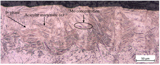
Figure 11.
Ti5Mo microstructure.
It is worth mentioning that a thorough review of the literature reveals that in all the previous studies [30,57,60,61], it was not possible to melt the Mo powder particles completely in the Ti-xMo alloy matrix due to the thermophysical difference and the powder particle distribution between the precursor powder and the Mo powder. It is the numerical simulation conducted by Dzogbewu et al. [60] which paved the way for possible printing of the Tix-Mo alloys without unmelted Mo particles via LPBF using an elemental powder blend. The numerical simulation reveals that if the Mo powder particle size is <20 µm, it would be possible to completely melt Mo in the Ti-xMo alloy matrix. The 1 µm powder particle size used in the current experiment is the main reason for the complete melting of Mo in the Ti5Mo alloy matrix. The small particle size of Mo also increases the packing density of the powder bed because the 1µm Mo powder particle filled the gap between the large 45 µm powder particles on the powder bed. The improved packing density of the powder bed enhances the wetting of the substrate preventing pronounced balling effect [62].
3.5. Microhardness
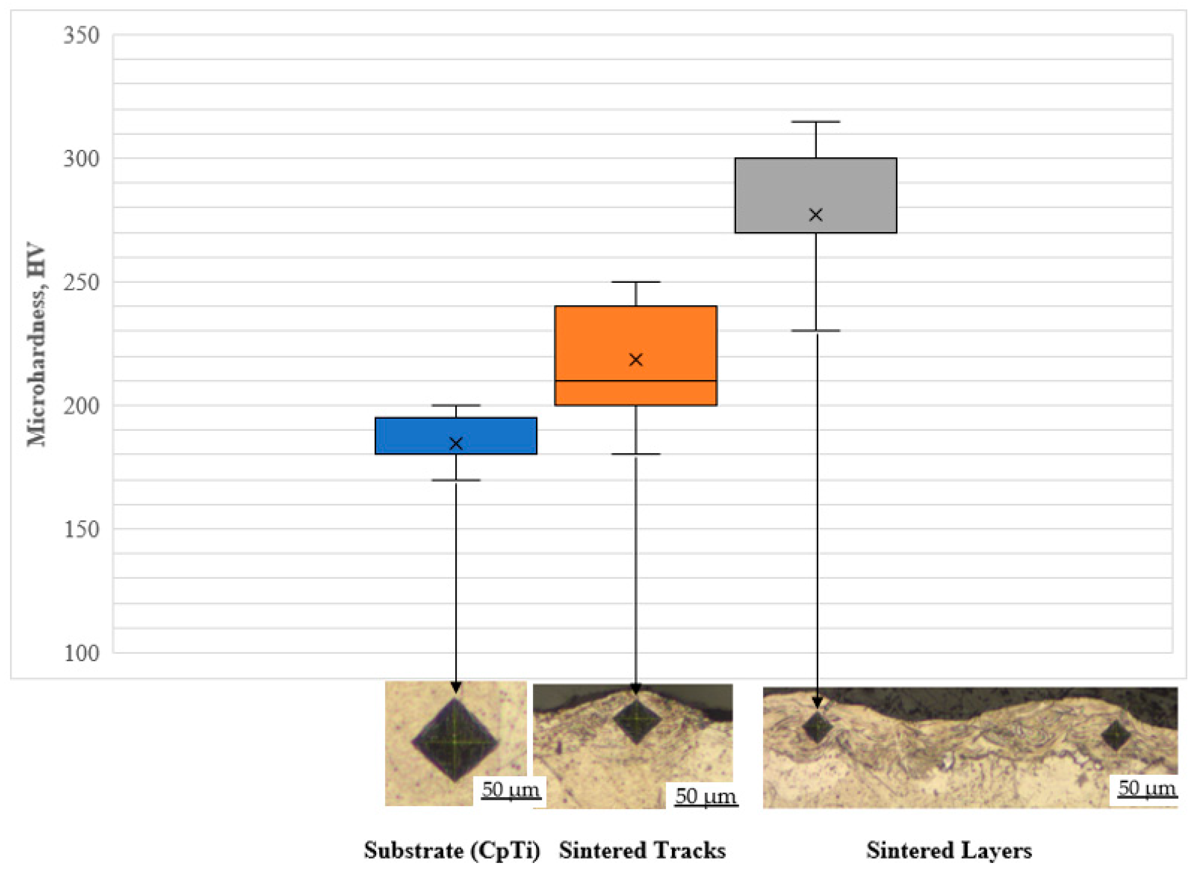
The microhardness of the Ti5Mo samples were investigated. From the box plot (Figure 12), it could be observed that the is a great degree of disparity between the microhardness values of the sintered tracks and the layers. This difference could be due to the experimental setup. The FM-700 Digital Vickers Microhardness Tester machine used a pyramid-shaped diamond indenter. The pyramid-shaped indenter indented the track and the substrate since the height of the tracks averagely equals the deposited powder layer thickness (50 µm). The depth of indentation at 200 g is more than 50 µm [63]. Hence, the microhardness of the CpTi substrate affects the measured microhardness value of the sintered tracks. Secondary, there is a high degree of disparity between the values obtained for the sintered tracks and layers. This could be attributed to the switching between the solidification structure. If the indenter indented a cellular region, a higher microhardness value is obtained, and if it indents a planar region, a lower microhardness value is obtained. This observation synchronised with what is normally observed when measuring the microhardness of a bulk LPBF sample due to the directional heat flux and the large thermal gradient [33]. The microhardness values obtained in the current experiment for the Ti15Mo layers fall within the range reported in the literature. Collins et al. [64] measured the microhardness of Ti-xMo (X = 0–25 wt.%) manufactured by laser engineered net-shaping (LENS™) and reported 280 HV for 5 wt.% Mo composition. Chen et al. [13] obtain microhardness values ranging from 381–451 HV for Ti10Mo bulk samples manufactured via a commercial arc-melting vacuum-pressure casting system. It is reported that the microhardness value increases with increasing Mo content. For the 5 wt.% Mo of the current experiment, the values obtained are in accordance with the literature, indicating that the obtained optimum principal process parameters (200 W, 1.0 m/s and hatch distance of 80 µm) could be used to produce a dense 3D object.

Figure 12.
Microhardness values of the Ti5Mo-sintered tracks and layers.
4. Conclusions
The optimum process parameters for in-situ alloying Ti5Mo powder blend via LPBF process were determined. The investigation attests that the LPBF process is a non-linear process and only a particular combination of the principal process parameters could yield optimum results. The penetration profile, 1⁄2 W = D = 1, and the normalised enthalpy theories were used to analyse the data. The normalised enthalpy theory did not align completely with all the results, since it lack some physics to explain the laser melting behaviour transition from the conduction mode to keyhole mode. The other theories explained the data thoroughly and 200 W, 1.0 m/s at a hatch distance of 80 µm was obtained as the optimum process parameters for manufacturing the Ti5Mo tracks and layers. The range of values obtained for the microhardness corresponds to what is reported in the literature, indicating that the optimum process parameters obtained could be used to produce a dense 3D structure without unmelted Mo particles with an improved homogenous microstructure.
Author Contributions
Conceptualization, T.C.D. and W.B.D.P.; methodology, T.C.D.; software, T.C.D.; validation, T.C.D. and W.B.D.P.; formal analysis, T.C.D. and W.B.D.P.; investigation, T.C.D.; resources, T.C.D. and W.B.D.P.; data curation, T.C.D.; writing—original draft preparation, T.C.D.; writing—review and editing, T.C.D. and W.B.D.P.; visualization, T.C.D. and W.B.D.P.; supervision, T.C.D. and W.B.D.P.; project administration, T.C.D. and W.B.D.P.; funding acquisition, T.C.D. and W.B.D.P. All authors have read and agreed to the published version of the manuscript.
Funding
This research was funded by the Collaborative Program in Additive Manufacturing (Contract No. CSIR-NLC-CPAM-21-MOA-CUT-01).
Data Availability Statement
The raw/processed data required to reproduce these findings can be shared on request.
Conflicts of Interest
The authors declare that they have no known competing financial interest or personal relationships that could have appeared to influence the work reported in this paper.
References
- Niinomi, M. Recent research and development in titanium alloys for biomedical applications and healthcare goods. Sci. Technol. Adv. Mater. 2003, 4, 445–454. [Google Scholar] [CrossRef] [Green Version]
- Nhlapo, N.; Dzogbewu, T.C.; De Smidt, O. A systematic review on improving the biocompatibility of titanium implants using nanoparticles. Manuf. Rev. 2020, 7, 31. [Google Scholar] [CrossRef]
- Nicholson, J.W. Titanium Alloys for Dental Implants: A Review. Prosthesis 2020, 2, 100–116. [Google Scholar] [CrossRef]
- Niinomi, M.; Liu, Y.; Nakai, M.; Liu, H.; Li, H. Biomedical titanium alloys with Young’s moduli close to that of cortical bone. Regen. Biomater. 2016, 3, 173–185. [Google Scholar] [CrossRef] [PubMed] [Green Version]
- Geetha, M.; Singh, A.K.; Asokamani, R.; Gogia, A.K. Ti based biomaterials, the ultimate choice for orthopaedic implants—A review. Prog. Mater. Sci. 2009, 54, 397–425. [Google Scholar] [CrossRef]
- Sandu, A.V.; Baltatu, M.S.; Nabialek, M.; Savin, A.; Vizureanu, P. Characterization and Mechanical Proprieties of New TiMo Alloys Used for Medical Applications. Materials 2019, 12, 2973. [Google Scholar] [CrossRef] [Green Version]
- Mohammed, M.T. Beta Titanium Alloys: The Lowest Elastic Modulus for Biomedical Applications: A Review. Int. J. Mater. Metall. Eng. 2016, 8, 822–827. [Google Scholar] [CrossRef]
- Jakubowicz, J. Special Issue: Ti-Based Biomaterials: Synthesis, Properties and Applications. Materials 2020, 13, 1696. [Google Scholar] [CrossRef] [Green Version]
- Lourenço, M.L.; Cardoso, G.C.; Sousa, K.; Donato, T.A.G.; Pontes, F.M.L.; Grandini, C.R. Development of novel Ti-Mo-Mn alloys for biomedical applications. Sci. Rep. 2020, 10, 6298. [Google Scholar] [CrossRef] [Green Version]
- Raffa, M.L.; Nguyen, V.H.; Hernigou, P.; Flouzat-Lachaniette, C.H.; Haiat, G. Stress shielding at the bone-implant interface: Influence of surface roughness and of the bone-implant contact ratio. J. Orthop. Res. 2021, 39, 1174–1183. [Google Scholar] [CrossRef]
- Huiskes, R.; Weinans, H.; Van Rietbergen, B. The Relationship between Stress Shielding and Bone Resorption around Total Hip Stems and the Effects of Flexible Materials. Clin. Orthop. Relat. Res. 1992, 274, 124–134. [Google Scholar] [CrossRef] [Green Version]
- Ho, W.; Ju, C.; Lin, J.C. Structure and properties of cast binary Ti–Mo alloys. Biomaterials 1999, 20, 2115–2122. [Google Scholar] [CrossRef]
- Lee, E.-B.; Han, M.-K.; Kim, B.-J.; Song, H.-J.; Park, Y.-J. Effect of molybdenum on the microstructure, mechanical properties and corrosion behavior of Ti alloys. Int. J. Mater. Res. 2014, 105, 847–853. [Google Scholar] [CrossRef]
- Sung, B.-S.; Park, T.-E.; Yun, Y.-H. Microstructures and Electrochemical Behavior of Ti-Mo Alloys for Biomaterials. Adv. Mater. Sci. Eng. 2015, 2015, 872730. [Google Scholar] [CrossRef] [Green Version]
- Zhang, L.-B.; Wang, K.-Z.; Xu, L.-J.; Xiao, S.-L.; Chen, Y.-Y. Effect of Nb addition on microstructure, mechanical properties and castability of β-type Ti–Mo alloys. Trans. Nonferrous Met. Soc. China 2015, 25, 2214–2220. [Google Scholar] [CrossRef]
- Almeida, A.; Gupta, D.; Vilar, R. Laser-assisted development of titanium alloys: The search for new biomedical materials. Proc. SPIE 2010, 7994, 79941U. [Google Scholar] [CrossRef]
- Disegi, J.; Roach, M.D.; McMillan, R.D.; Shultzabarger, B.T. Alpha plus beta annealed and aged Ti-15 Mo alloy for high strength implant applications. J. Biomed. Mater. Res. Part B Appl. Biomater. 2017, 105, 2010–2018. [Google Scholar] [CrossRef]
- Chen, Y.-Y.; Xu, L.-J.; Liu, Z.-G.; Kong, F.-T.; Chen, Z.-Y. Microstructures and properties of titanium alloys Ti-Mo for dental use. Trans. Nonferrous Met. Soc. China 2006, 16, S824–S828. [Google Scholar] [CrossRef]
- Zhan, Y.; Li, C.; Jiang, W. β-type Ti-10Mo-1.25Si-xZr biomaterials for applications in hard tissue replacements. Mater. Sci. Eng. C 2012, 32, 1664–1668. [Google Scholar] [CrossRef]
- Xu, L.; Chen, Y.; Liu, Z.; Kong, F. The microstructure and properties of Ti–Mo–Nb alloys for biomedical application. J. Alloys Compd. 2008, 453, 320–324. [Google Scholar] [CrossRef]
- Li, C.; Zhan, Y.; Jiang, W. β-Type Ti–Mo–Si ternary alloys designed for biomedical applications. Mater. Des. 2012, 34, 479–482. [Google Scholar] [CrossRef]
- Robert, B. Materials for Medical Application. De Gruyter. 2020. Available online: https://www.amazon.com/Materials-Medical-Application-Gruyter-Stem/dp/3110619199 (accessed on 16 November 2021).
- Kumar, S.; Narayanan, T.S. Corrosion behaviour of Ti–15Mo alloy for dental implant applications. J. Dent. 2008, 36, 500–507. [Google Scholar] [CrossRef] [PubMed]
- Júnior, J.R.S.M.; Nogueira, R.A.; De Araújo, R.O.; Donato, T.A.G.; Arana-Chavez, V.E.; Claro, A.P.R.A.; Moraes, J.C.S.; Buzalaf, M.A.R.; Grandini, C.R. Preparation and characterization of Ti-15Mo alloy used as biomaterial. Mater. Res. 2011, 14, 107–112. [Google Scholar] [CrossRef] [Green Version]
- F2066-08; Standard Specification for Wrought Titanium-15 Molybdenum Alloy for Surgical Implant Applications (UNS R58150). ASTM International: West Conshohocken, PA, USA, 2008; pp. 1–5. Available online: https://www.astm.org/Standards/F2066.htm (accessed on 16 November 2021).
- Raji, S.A.; Popoola, A.P.I.; Pityana, S.L.; Popoola, O.M. Characteristic effects of alloying elements on β solidifying titanium aluminides: A review. Heliyon 2020, 6, e04463. [Google Scholar] [CrossRef] [PubMed]
- Jablokov, V.; Nutt, M.; Richelsoph, M.; Freese, H. The Application of Ti-15Mo Beta Titanium Alloy in High Strength Structural Orthopaedic Applications. J. ASTM Int. 2005, 2, 491–508. [Google Scholar] [CrossRef]
- Dzogbewu, T.C.; Amoah, N.; Fianko, S.K.; Afrifa, S.; de Beer, D. Additive manufacturing towards product production: A bibliometric analysis. Manuf. Rev. 2022, 9, 1. [Google Scholar] [CrossRef]
- Etesami, S.A.; Fotovvati, B.; Asadi, E. Heat treatment of Ti-6Al-4V alloy manufactured by laser-based powder-bed fusion: Process, microstructures, and mechanical properties correlations. J. Alloys Compd. 2022, 895, 162618. [Google Scholar] [CrossRef]
- Dzogbewu, T.C. Laser powder bed fusion of Ti15Mo. Results Eng. 2020, 7, 100155. [Google Scholar] [CrossRef]
- Liu, H.; Niinomi, M.; Nakai, M.; Hieda, J.; Cho, K. Changeable Young’s modulus with large elongation-to-failure in β-type titanium alloys for spinal fixation applications. Scr. Mater. 2014, 82, 29–32. [Google Scholar] [CrossRef]
- Yadroitsev, I.; Krakhmalev, P.; Yadroitsava, I. Hierarchical design principles of selective laser melting for high quality metallic objects. Addit. Manuf. 2015, 7, 45–56. [Google Scholar] [CrossRef]
- Khairallah, S.A.; Anderson, A.T.; Rubenchik, A.; King, W.E. Laser powder-bed fusion additive manufacturing: Physics of complex melt flow and formation mechanisms of pores, spatter, and denudation zones. Acta Mater. 2016, 108, 36–45. [Google Scholar] [CrossRef] [Green Version]
- Zenani, A.; Dzogbewu, T.C.; Du Preez, W.B.; Yadroitsev, I. Optimum Process Parameters for Direct Metal Laser Sintering of Ti6Al Powder Blend. Univers. J. Mech. Eng. 2020, 8, 170–182. [Google Scholar] [CrossRef]
- Hussain, S.Z.; Kausar, Z.; Koreshi, Z.U.; Sheikh, S.R.; Rehman, H.Z.U.; Yaqoob, H.; Shah, M.F.; Abdullah, A.; Sher, F. Feedback Control of Melt Pool Area in Selective Laser Melting Additive Manufacturing Process. Processes 2021, 9, 1547. [Google Scholar] [CrossRef]
- Struers Company. Metallographic Products, Knowledge and Service|Struers.com. Available online: https://www.struers.com/en (accessed on 17 January 2022).
- Chan, C.L.; Mazumder, J.; Chen, M.M. Three-dimensional axisymmetric model for convection in laser-melted pools. Mater. Sci. Technol. 1987, 3, 306–311. [Google Scholar] [CrossRef]
- Rai, R.; Elmer, J.W.; Palmer, T.A.; DebRoy, T. Heat transfer and fluid flow during keyhole mode laser welding of tantalum, Ti–6Al–4V, 304L stainless steel and vanadium. J. Phys. D Appl. Phys. 2007, 40, 5753–5766. [Google Scholar] [CrossRef] [Green Version]
- Hann, D.; Iammi, J.; Folkes, J. A simple methodology for predicting laser-weld properties from material and laser parameters. J. Phys. D Appl. Phys. 2011, 44, 445401. [Google Scholar] [CrossRef]
- Madison, J.D.; Aagesen, L. Quantitative characterization of porosity in laser welds of stainless steel. Scr. Mater. 2012, 67, 783–786. [Google Scholar] [CrossRef]
- King, W.E.; Barth, H.D.; Castillo, V.M.; Gallegos, G.F.; Gibbs, J.W.; Hahn, D.E.; Kamath, C.; Rubenchik, A.M. Observation of keyhole-mode laser melting in laser powder-bed fusion additive manufacturing. J. Mater. Process. Technol. 2014, 214, 2915–2925. [Google Scholar] [CrossRef]
- Sing, S.; Huang, S.; Goh, G.; Tey, C.; Tan, J.; Yeong, W. Emerging metallic systems for additive manufacturing: In-situ alloying and multi-metal processing in laser powder bed fusion. Prog. Mater. Sci. 2021, 119, 100795. [Google Scholar] [CrossRef]
- Kou, S.; Limmaneevichitr, C.; Wei, P.S. Oscillatory Marangoni flow: A fundamental study by conduction-mode laser spot welding. Weld. J. 2011, 90, 229–240. [Google Scholar]
- Qiu, C.; Panwisawas, C.; Ward, M.; Basoalto, H.C.; Brooks, J.W.; Attallah, M. On the role of melt flow into the surface structure and porosity development during selective laser melting. Acta Mater. 2015, 96, 72–79. [Google Scholar] [CrossRef] [Green Version]
- Keene, B.J. Review of data for the surface tension of pure metals. Int. Mater. Rev. 1993, 38, 157–192. [Google Scholar] [CrossRef]
- Rayleigh, L. XIX. On the instability of cylindrical fluid surfaces. Lond. Edinb. Dublin Philos. Mag. J. Sci. 1892, 34, 177–180. [Google Scholar] [CrossRef] [Green Version]
- Fischer, P.; Romano, V.; Weber, H.; Karapatis, N.; Boillat, E.; Glardon, R. Sintering of commercially pure titanium powder with a Nd:YAG laser source. Acta Mater. 2003, 51, 1651–1662. [Google Scholar] [CrossRef]
- Krehl, O.K.P. History of Shock Waves, Explosions and Impact—A Chronological and Biographical Reference; Springer: Berlin/Heidelberg, Germany, 2009. [Google Scholar] [CrossRef]
- Torkamany, M.; Ghaini, F.M.; Poursalehi, R.; Kaplan, A. Combination of laser keyhole and conduction welding: Dissimilar laser welding of niobium and Ti-6Al-4V. Opt. Lasers Eng. 2016, 79, 9–15. [Google Scholar] [CrossRef]
- Yang, J.; Han, J.; Yu, H.; Yin, J.; Gao, M.; Wang, Z.; Zeng, X. Role of molten pool mode on formability, microstructure and mechanical properties of selective laser melted Ti-6Al-4V alloy. Mater. Des. 2016, 110, 558–570. [Google Scholar] [CrossRef]
- Lathabai, S.; Jarvis, B.; Barton, K. Comparison of keyhole and conventional gas tungsten arc welds in commercially pure titanium. Mater. Sci. Eng. A 2001, 299, 81–93. [Google Scholar] [CrossRef]
- AZoM. Titanium Alloys—Physical Properties. AZO Materials. 2002. Available online: https://www.azom.com/article.aspx?ArticleID=1341 (accessed on 19 August 2021).
- Palik, E.D. Handbook of Optical Constants of Solids; Elsevier: Amsterdam, The Netherlands, 2012; Volume 1. [Google Scholar]
- Nakamura, S.; Sakurai, M.; Kamimuki, K.; Inoue, T.; Ito, Y. Detection technique for transition between deep penetration mode and shallow penetration mode in CO2 laser welding of metals. J. Phys. D Appl. Phys. 2000, 33, 2941–2948. [Google Scholar] [CrossRef]
- Shi, Y.; Yan, C.; Zhou, Y.; Wu, J.; Wang, Y.; Yu, S.; Chen, Y. Metal Materials for Additive Manufacturing; Elsevier: Amsterdam, The Netherlands, 2021; pp. 403–595. [Google Scholar] [CrossRef]
- Xu, J.Q.; Chen, L.; Choi, H.; Li, X.C. Theoretical study and pathways for nanoparticle capture during solidification of metal melt. J. Phys. Condens. Matter 2012, 24, 255304. [Google Scholar] [CrossRef]
- Vrancken, B.; Thijs, L.; Kruth, J.-P.; Van Humbeeck, J. Microstructure and mechanical properties of a novel β titanium metallic composite by selective laser melting. Acta Mater. 2014, 68, 150–158. [Google Scholar] [CrossRef] [Green Version]
- Bertoli, U.S.; Guss, G.; Wu, S.; Matthews, M.J.; Schoenung, J.M. In-situ characterization of laser-powder interaction and cooling rates through high-speed imaging of powder bed fusion additive manufacturing. Mater. Des. 2017, 135, 385–396. [Google Scholar] [CrossRef]
- Shi, Q.; Gu, D.; Xia, M.; Cao, S.; Rong, T. Effects of laser processing parameters on thermal behavior and melting/solidification mechanism during selective laser melting of TiC/Inconel 718 composites. Opt. Laser Technol. 2016, 84, 9–22. [Google Scholar] [CrossRef]
- Dzogbewu, T.C.; Yadroitsev, I.; Krakhmalev, P.; Yadroitsava, I.; Plessis, A.D. Optimal process parameters for in situ alloyed Ti15Mo structures by laser powder bed fusion. In Proceedings of the Solid Freeform Fabrication 2017: 28th Annual International Solid Freeform Fabrication Symposium—An Additive Manufacturing Conference, SFF 2017, Austin, TX, USA, 7–9 August 2017; pp. 75–96. [Google Scholar]
- Huber, F.; Rasch, M.; Schmidt, M. Laser Powder Bed Fusion (PBF-LB/M) Process Strategies for In-Situ Alloy Formation with High-Melting Elements. Metals 2021, 11, 336. [Google Scholar] [CrossRef]
- Das, S. Physical Aspects of Process Control in Selective Laser Sintering of Metals. Adv. Eng. Mater. 2003, 5, 701–711. [Google Scholar] [CrossRef]
- Broitman, E. Indentation Hardness Measurements at Macro-, Micro-, and Nanoscale: A Critical Overview. Tribol. Lett. 2017, 65, 23. [Google Scholar] [CrossRef] [Green Version]
- Collins, P.C.; Banerjee, R.; Banerjee, S.; Fraser, H.L. Laser deposition of compositionally graded titanium–vanadium and titanium-molybdenum alloys. Mater. Sci. Eng. A 2003, 352, 118–128. [Google Scholar] [CrossRef]


Publisher’s Note: MDPI stays neutral with regard to jurisdictional claims in published maps and institutional affiliations. |
© 2022 by the authors. Licensee MDPI, Basel, Switzerland. This article is an open access article distributed under the terms and conditions of the Creative Commons Attribution (CC BY) license (https://creativecommons.org/licenses/by/4.0/).