Abstract
Aluminium matrix composites (AlMCs) of AA7075 aluminium alloy reinforced with 0.5 and 1 wt.% multiwall carbon nanotubes (MWCNTs) were fabricated with powder metallurgy techniques using three different mechanical milling strategies, varying the milling energy and the stage in which the reinforcements were added to the pre-alloyed matrix powders. In this paper, we focus on the influence of these parameters on the dispersion of MWCNTs. Characterization of the obtained composite powders by X-ray diffraction and scanning electron microscopy showed that the evolution of the particle size and morphology of the composite powders is influenced by milling conditions and MWCNT content; however, under the conditions tested in this study, there were no significant differences in crystallite size and lattice strain. The best distribution of the reinforcements was obtained after milling 7075 powders and MWCNTs in a high-energy cycle (HEBM), varying the rotation speed between 1200 and 1300 rpm. Raman spectroscopy was used to assess the damage induced by the milling process in the nanotubes, and no reaction products were detected under any of the tested conditions. Nanoindentation tests were performed to measure the elastic modulus and hardness of the composite powders, revealing that the best mechanical behaviour was achieved by the 7075-0.5 wt.% MWCNT composites obtained by the HEBM route.
1. Introduction
Aluminium is considered an ideal metal matrix for lightweight, high-strength composites, which are widely applied in the automotive and aerospace industries [1]. In recent decades, aluminium matrix composites (AlMCs) have been reinforced with ceramic particles, such as TiC, SiC, Al2O3, Y2O3, AlN, Si3N4 and TiB2, in order to improve properties such as strength at elevated temperature, fatigue performance, elastic stiffness and wear resistance [2,3,4,5,6,7,8,9].
However, in recent years, extensive work has been carried out on carbon nanotubes (CNTs) due to their exceptional properties [10], such as high modulus of elasticity (1–5 TPa), high resistance (50–60 GPa), chemical stability, high conductivity and low weight. Such characteristics make CNTs very attractive as a reinforcers for production of lightweight metal matrix composites (MMCs). Although the mechanical properties of multiwalled carbon nanotubes (MWCNTs) are lower (Young’s modulus is up to 1.8 TPa) than those of single-walled carbon nanotubes (SWCNTs), their higher chemical stability and lower production cost make them more suitable for industrial applications [11].
As is well known, improvement in the mechanical properties of a ductile matrix, such as aluminium, with the dispersion of CNT reinforcements is mainly attributed to a combination of strengthening mechanisms, such as thermal mismatch, dispersion strengthening by Orowan looping, load transfer [12] and grain size refinement. The first mechanism relates to the indirect strengthening caused by the dislocations created in the matrix due to the mismatch in the coefficient of thermal expansion between the aluminium and the embedded CNTs during the production process. The dispersion strengthening by Orowan looping across reinforcements inhibits dislocation motion and occurs during plastic deformation. The interfacial load-transfer strengthening contribution is based on the classical load-transfer mechanism of the ductile matrix in the strong reinforcing phase and depends on the interfacial bonds between the matrix and reinforcements over a minimum length (critical length). Finally, grain-refinement or Hall–Petch strengthening is triggered by the introduction of dispersed fine particles and provides additional strengthening to the matrix. Consequently, to achieve the expected properties of nanocomposites, the production processes should guarantee a fine microstructure, the preservation of the integrity of the nanotubes and their adequate dispersion in the matrix; otherwise, the ductility, strength and toughness would be affected. Those factors remain considerable challenges of AlMC-CNT production.
In recent years, considerable efforts have been made to achieve the correct dispersion of CNTs in the metal matrix using different dispersion techniques, such as pre-dispersion of CNTs in polyvinyl alcohol (PVA) [13], use of surfactants [14], prior acid treatment of the CNTs [15] and a solution coating technique that relies on the electrostatic self-assembly of CNTs on the aluminium powder surface [16].
Different liquid-state techniques, such as plasma spraying, cold spraying, thermal spraying and squeeze casting, have been used to fabricate bulk composites reinforced with CNTs [17]. However, poor dispersion of CNTs and unfavourable chemical reactions between CNTs and the metal matrix, which affect the load-transfer strengthening contribution, have been identified as crucial problems in the development of these liquid-state techniques.
One of the advantages of solid-state techniques is the relatively low processing temperatures, which minimize interfacial reactions and allow for attainment of very fine microstructures. In the first stage, CNTs are blended and integrated into the matrix metal powder, followed by hot consolidation of the mixture as a hot extrusion or hot rolling processes. Due to its low cost and high process adaptability, powder metallurgy is the most prevalent method used for the fabrication of CNT/Al composites, which leads to an increase in the mechanical properties of the products [18,19,20].
High-energy ball milling (HEBM) has proven to be a very efficient process for synthesis metal matrix composite powders, as it allows for incorporation of the metal and the reinforcing phases into each powder particle. It is thus considered an effective technique to promote CNT dispersion into aluminium powder and to achieve fine-grain structures. Furthermore, the use of mechanical milling to produce CNT-reinforcing Al MMCs remains limited [21]. In ductile metals, it is well known that HEBM develops in stages, starting with particle flattening, cold welding, layering and refracturing of the powder particle mixture. As the dimensions of CNTs are much smaller than those of typical Al powders, they can be enveloped by the deformed metal and protected from the direct impact of the milling media, refining the microstructure and ensuring the homogeneous and uniform distribution of the reinforcement. However, it has been demonstrated that if the milling time is excessively prolonged, the fracture and amorphization of the CNTs take place, making them excessively reactive with aluminium during subsequent high-temperature processing cycles [22].
HEBM is a dynamic and complex process and; therefore, the optimization of variables is important to achieve the desired product. As a consequence, in recent years, intense research has been carried out to determine the effect of ball milling conditions (speed, time, milling media, ball-to-powder weight ratio (BPR), milling atmosphere, temperature and the addition of a process control agent (PCA)) on the microstructural evolution and induced properties of the composite [23,24,25]. However, the scientific literature related to CNT-reinforced metal matrix composites is still fairly limited, with significantly more studies conducted on aluminium matrix composites [17] (p. 2); although significant strengthening has been reported in some cases, very few papers report the use of commercial Al alloys [19,26,27,28] (p. 2), to produce CNTs/AlMCs.
Therefore, only a few studies have been published on the reinforcement of 7075 aluminium matrices with CNTs. Uriza-Vega et al. [29] studied the influence of CNT content (0–3 wt.%) on the properties of composites manufactured via powder metallurgy and hot extrusion. In order to improve nanotube dispersion, a sonication stage involving isopropyl alcohol was performed. Their results indicate that for CNT contents above 2.0 wt.%, mechanical behaviour of the composites shows a noticeable improvement, with ductility close to that reported in the literature for Al7075 commercial alloy. Jagannatham et al. [30] produced composites by milling with different amounts of reinforcements, followed by conventional sintering and hot extrusion. In this work, the authors observed that properties such as hardness, as well as tensile and dry sliding wear performance of the manufactured composites were enhanced with the addition of CNTs up to 1 wt.%, and further addition of CNTs led to a decrease in mechanical and tribological properties. Zhang et al. [31] analysed the precipitation-hardening behavior of CNTs/7075 Al composites with 1 wt.% CNT content during aging treatment. The CNTs shortened the peak aging time due to dislocations generated between the CNTs and the Al matrix, retarding the over-aging process.
In line with these studies, the objective of our work was to identify a manufacturing method that is easily transferable to an industrial process for the production of new high-strength 7075 composites through a mechanical milling process followed by hot extrusion. MWCNTs were selected due to their low cost, and two reinforcement percentages (0.5 and 1 wt.%) were compared. Three strategies with short milling times were established, including ball milling cycles in which the rotation speed was alternated between two values in order to improve the efficiency of this stage.
As previously mentioned, the proposed processes should lead to a uniform dispersion of MWCNTs into a fine-grained AA7075 matrix, avoiding their agglomeration and clustering, preserving their integrity and ensuring a good interfacial bonding between nanotubes and the aluminium [2,11,23] (p. 1, p. 1, p. 3). Therefore, in this paper, we focus on verifying the effect of the milling conditions on these characteristics, which are key to obtaining the expected properties in the final composites. The influence on the morphology and hardness of the AA7075-MWCNT composite powders is analysed in detail. In further work, the results of mechanical tests performed on the profiles of composites obtained by hot extrusion will be presented.
2. Materials and Methods
2.1. Raw Materials
Inert gas-atomized AA7075 powder from aluminium alloy ingots fabricated and supplied by ECKA Granules Germany GmbH (Velden, Germany),was used as the matrix for the composite material. The particle size distribution indicated in the product’s technical sheet is ×10 = 26.6 µm; ×50 = 41.3 µm; ×90 = 63.3 µm, according to ISO 13320:2009 particle size analysis laser diffraction methods. The chemical composition of the pre-alloyed powders was (wt.%): 5.5 Zn, 2.6 Mg, 1.5 Cu, 0.08 Fe, 0.11 Si, <0.01 Mn, 0.26 Cr, <0.01 Ti and Al balance.
The MWCNT nanotubes, used as reinforcement were supplied by IoLiTec Nanomaterials (Heilbronn, Germany), with a purity > 95%. According to the data sheet, the outer diameter (OD) was 10–20 nm, and the average length was 1–2 μm.
2.2. AA7075-MWCNT Composite Powder Preparation
To obtain a homogeneous distribution of MWCNTs during the manufacture of AA7075-MWCNT composite powders, a ball milling (BM) process was employed with the use of a horizontal rotary ball mill (Simoloyer®CM01 ZOZ GmbH, Wenden, Germany) operating under a high-purity argon atmosphere to avoid excessive metal oxidation.
The ball-to-powder ratio (BPR) was 10:1. The balls employed for milling (AISI 420) were 5 mm in diameter. An amount of 0.5wt.% amide micro wax (Licowax® C micro powder, Clariant, Muttenz, Switzerland) was added to the powders as a process control agent (PCA) to prevent excessive cold welding of the powders and detrimental welding of the powder with the components of the mill (balls, walls and blades).
Different percentages (1 and 0.5 wt.%) of MWCNTs were added to the pre-alloyed AA7075 powders. These percentages were selected based on a bibliographic review carried out by the authors [11,21,29] (p. 1, p. 2, p. 3). High concentrations of CNTs can result in a negative effect on the mechanical behaviour of the aluminium composites due to the non-homogeneous dispersion of nanotubes, as indicated in previous studies. For example, Esawi et al. [32] observed that for CNT contents higher than 2 wt.%, clusters are formed in the processed aluminium compounds, and therefore, the increase in the percentage of CNTs does not produce the expected improvements in terms of mechanical properties. Jagannatham et al. [30] (p. 3) obtained similar results. They observed that for CNT additions greater than 1 wt.%, the mechanical and tribological properties of 7075-CNT compounds decreased.
To optimize the dispersion of MWCNTs in composite powders, three mechanical ball milling strategies were compared in this study. These were carried out by following a cyclic operation mode in which the rotation speed was varied over 1 min cycles, maintaining the higher speed indicated in first place for 48 s and the second lower speed for the last 12 s. Previous research [33] showed that cyclic operation improves the efficiency of the process by avoiding the agglomeration and sticking of particles and reducing the milling time required to obtain a smaller-grained structure compared with conventional milling.
Low-energy ball milling (LEBM) was proposed to achieve an adequate dispersion by minimizing the deterioration of the MWCNTs. Thus, AA7075 powders and MWCNTs were introduced into the mill together and milled in 300/200 rpm cycles for 4 h. In the HEBM, MWCNTs were also milled with pre-alloyed powder particles, but a higher-kinetic-energy strategy was used (alternating the speed between 1300 and 1000 rpm for 4 h). The aim of this strategy was to achieve dispersion of the MWCNTs and their incorporation into the matrix at the same time that the plastic deformation of the particles occurs. Finally, the H + LEBM strategy was aimed to initially increase the resistance of the matrix by cold working before proceeding with dispersion of the nanotubes. Therefore, AA7075 particles were milled alone using a high-energy cycle (1300/1000 rpm for 4 h), followed by the addition of MWCNTs and a final mixing stage carried out for 2 h at low speed (200 rpm) to avoid deterioration of the nanotubes. Table 1 summarizes the parameters of the three strategies.

Table 1.
Route of ball milling.
To study variations in sizes and morphologies of the composite powders and verify the dispersion of nanotubes over time, samples were extracted after 2 and 4 h for the LE and HE methods and after, 2, 4 and 6 h for the H + LE methods.
2.3. Material Characterization
The pre-alloyed AA7075 powders in as-received and ball-milled conditions were characterised by studying their morphology and size distribution, as well as the microstructure of the particles. Morphological characterization was performed by SEM using a dual-beam Helios NanoLab™ 400 FEI instrument (Nanolab Technologies, Milpitas, CA, USA) with a resolution 1.0 nm at 20 kV equipped with EDS and INCA Energy software (Oxford Instruments, Abingdon, UK). To investigate the microstructure and the possible presence of intermetallic phases or elementary segregation in the as-received atomized particles, powder samples were embedded in resin and then prepared for metallographic observation using 10% NaOH as an etching reagent. The particle size distribution of powders was calculated by image analysis using ImageJ digital image-processing open source software (Wayne Rasband-NIH, USA) The diameters of 100 particles from five SEM images taken from each powder sample were measured.
Initial microstructural characterization of the MWCNTs was carried out by means of a JEOL JEM-2010 FEG (200 kV) ultra-high-resolution TEM microscope (0.19 nm dot; 0.10 nm line) with EDS microanalysis (JEOL Ltd., Tokyo, Japan).
The composite particles were analysed by Raman spectroscopy to quantitatively determine possible damage to the MWCNTs. Raman spectra were measured with a Horiba Jobin Yvon LabRam HR800UV spectrometer (Horiba, Tokyo, Japan) equipped with LabSPEC V.5 software (HORIBA France SAS, Longjumeau, France). Samples were excited with a HeNe laser (632.8 nm) focused on the samples using a 50× objective. Measurements were carried out under two conditions. First, the spectra were collected in a frequency range between 30–3500 cm−1 and 20 scans with 15 s exposure time to detect all possible Raman active modes. However, due to the high level of fluorescence produced by some samples, for better determination of the D and G band heights, it was necessary to reduce the excitation time of the sample, narrowing the frequency range to 1000 to 2000 cm−1 and reducing the number of scans to 10, with 5 s exposure time.
Crystal structures, crystallite sizes and lattice strain due to the presence of lattice defects of materials were evaluated by X-ray diffraction (XRD) using a Cu Kα (λ = 0.15406 nm) radiation source in a Siemens model D-5000 diffractometer (KS Analytical Systems, Aubrey, TX, USA). Scans were collected in the 2θ range of 5–90°; smaller angular steps of 2θ = 0.02° and a fixed counting time of 4 s were used to measure the intensity of each Bragg reflection.
The Bragg angles, 2θ, corresponding to different peaks were noted, and the values of interplanar spacing (d-spacing) obtained from the computerized output were compared with the standard values from the International Centre for Diffraction Data’s powder diffraction file (ICDD-PDF).
The position of the 2θ peaks, their intensity (Ihkl) and the full width at half maximum (FWHM) of the height of the peak (βhkl)0 were determined with EVA (version 14, Bruker, Billerica, MA, USA).
The crystallite size and lattice strain were estimated using Scherrer’s formula as follows [34].
The lattice strain of the matrix (ε) was estimated using the following equation:
where t is the crystallite size (Å), K is a constant (0.9), λ is the wavelength of the Cu radiation (1.54056Å), βhkl corresponds to the mean width of the analysed reflection (radians) and θ is the Bragg angle.
The instrumental corrected broadening [35] corresponding to a diffraction peak was estimated using the following equation:
Instrumental correction was carried out using the previous expression with a standard quartz pattern (ICCD card 00-033-1161).
The modulus of elasticity (E) and hardness (H) of the AA7075-MWCNT composites were determined with a NanoIndenter XP (MTS NanoSystem) with a DCM (dynamic control module) for ultra-low-load mechanical property characterization and a continuous stiffness measurement (CSM) attachment for continuous determination of E and H. The nanoindentation test involves indenting a specimen with a very low load using a high-precision instrument that records the load and penetration depth continuously. In the nanoindentation test, the elastic modulus (E) and hardness (H) were directly obtained from the measured load-penetration depth curves under loading/unloading through appropriate data analysis.
For these measurements, a CSM was used, which offers high-resolution nanoindentation testing. Unlike conventional indentation testing methods, the use of the CSM provides the advantage of measuring material hardness and elastic modulus as a continuous function of indenter penetration depth. The measurements were conducted with a three-sided pyramidal Berkovich diamond indenter tip with a tip radius of ~100 nm. The maximum penetration depth was 500 nm. This value was selected by taking into account the size of the aluminium powder.
A method formulated by Oliver and Pharr [36] was used to extract hardness and elastic modulus values from the load–displacement data according to ISO-14577-1. In order to manipulate and characterize the powder correctly, it was necessary to embed the powders in resin and ground and polish them until we attained a 3 µm diamond paste. One test series of 20 indentations each was performed for each material.
3. Results and Discussion
3.1. Microstructural Characterization of Raw Materials
Figure 1 displays SEM images of the as-received AA7075 powders used as the composite matrix. Most of the particles have spherical morphology. The high-magnification SEM image shows the orange skin-like topology of the particle surfaces, which represents a typical morphology for gas-atomized powders [37] (Figure 1b). The particle size distribution of the as-received atomized powders was determined by metallographic measurements analysis of more than 100 particles. The results are depicted in Table 2. An average grain size of 36 μm was determined.
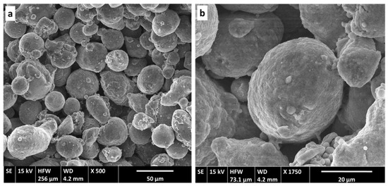
Figure 1.
Secondary electron (SE) images of as-received atomized AA7075 powders: (a) morphology of the powders; (b) detailed image of the topology of the surface.
Table 2.
Particle size distribution of the as-received atomized AA7075 powders.
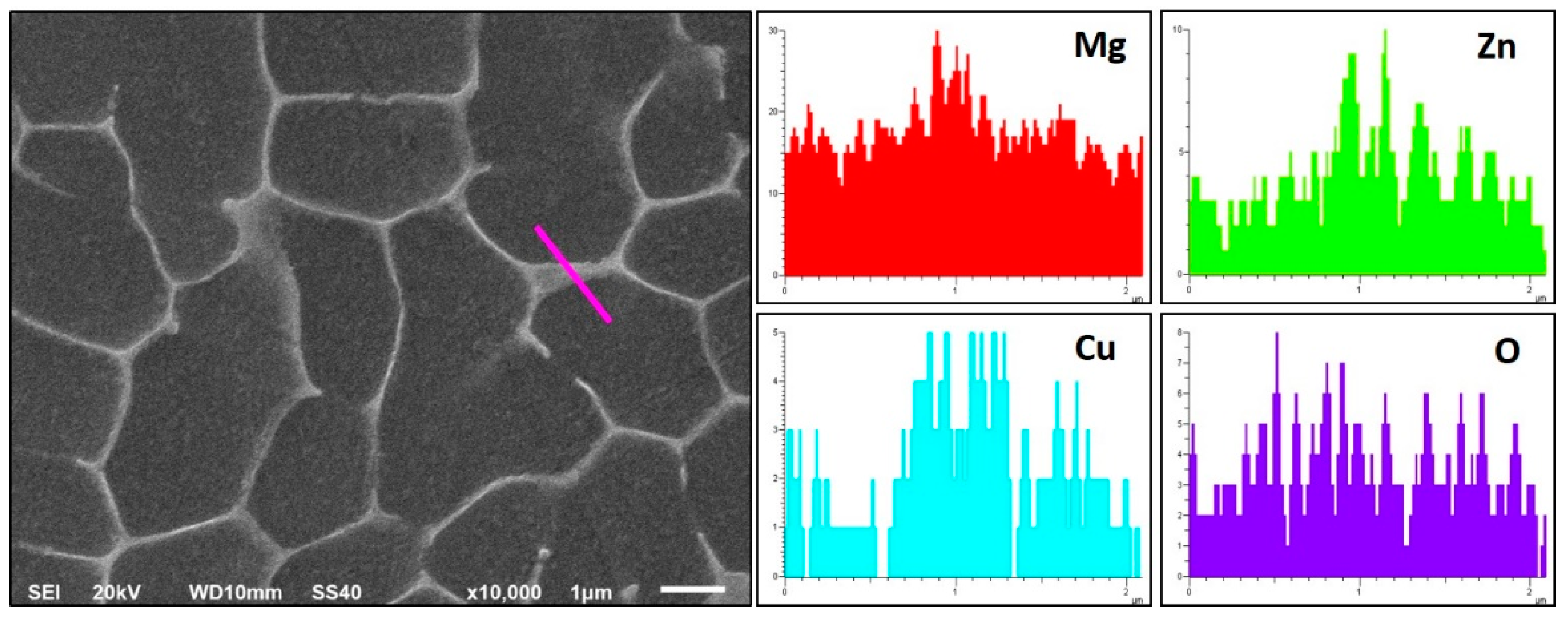
Examining the cross section of the particles (Figure 2), a combination of cellular and dendritic-like morphologies [38] can be observed, with cell or dendrite sizes between 1 µm and 8 μm. No precipitation of intermetallic phases was detected in the inter-dendritic spaces of the examined particles, but EDS analyses showed a clear segregation of Mg, Zn, Cu and O along boundaries (Figure 3).
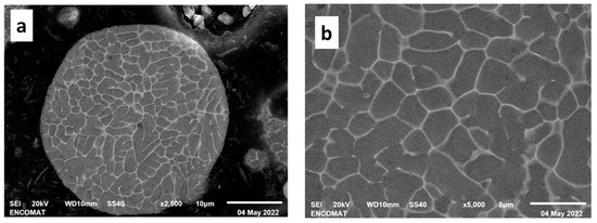
Figure 2.
SEM images of the fine solidification microstructure of AA7075 pre-alloyed powders: (a) cross section of the powder particle after etching with NaOH; (b) detailed image (a) showing the dimensions of the dendrites.
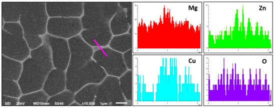
Figure 3.
EDS analysis of AA7075 particles along grain boundaries. The image on the left allows for determination of the position where the scan line was performed (pink line). The image on the right shows the elemental profiles from the scan.
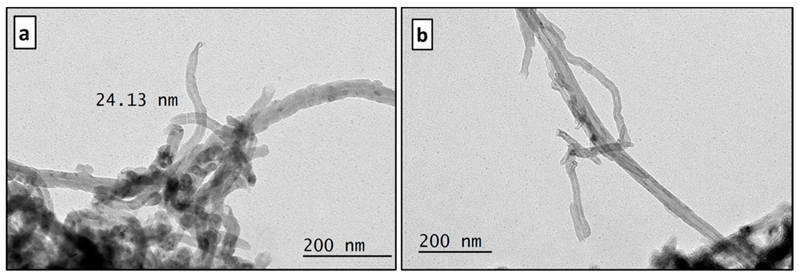
A study of the morphological characteristics of as-received MWCNTs was performed by HRTEM. Due to their strong tendencies to form bundles and aggregate together, their examination and characterization is difficult [39]. To solve this problem, a homogeneous suspension of a small amount of carbon nanotubes in ethanol was produced by ultrasonic stirring for 5 min. Then, a droplet was deposited on the sample holder and, after evaporation, was examined. Figure 4a shows bundles of MWCNTs that could not be adequately dispersed. This made it difficult to verify the dimensions of the tubules. An average outside diameter (OD) of between 10 and 20 nm, as indicated by the manufacturer’s technical data sheet, was estimated by 50 measurements made on the terminal tubules of different clusters (Figure 4b). A small fraction of nanotubes of OD > 30 nm was also detected. Due to the degree of entanglement of the MWCNTs, their average length could not be verified.

Figure 4.
HRTEM images showing: (a) clusters of MWCNTs; (b) an individual MWCNT.
3.2. Morphology and Size Evolution of Composite Particles and Dispersion of MWCNTs
As previously mentioned, one of the major obstacles to the effective use of CNTs as reinforcements in metal matrix composites is their agglomeration and poor distribution/dispersion within the metallic matrix. For this reason, determining the distribution of carbon nanotubes in the pre-alloyed AA7075 powders obtained according to three proposed milling methods constitutes the first stage of this study. In order to understand the mechanism of dispersion of the MWCNTs, it is necessary to consider the deformation process of the matrix powder particles as a function of the milling parameters.
3.2.1. High-Energy Ball Milling (HEBM) Route
This route was used to ensure the uniform distribution of CNTs in the MMCs and obtain an ultrafine-grained matrix in a short, single-stage process. Mechanical milling of AA7075 powders and MWCNTs was performed in 1 min cycles with 48 s of high rotation speed (1300 rpm) and 12 s of lower speed (1000 rpm) for 4 h. Samples of the milled powder were extracted for analysis at 2 h and 4 h.
Figure 5 shows the morphology of the composite powders with 0.5 and 1 wt.% MWCNTs after 2 h and 4 h of HE ball milling, which resulted in particles with a clearly irregular shape. During the first two hours, under the high-energy impacts of the balls, the initially spherical particles undergo severe deformation and are repeatedly flattened and transformed into flakes. The cold welding of the flakes leads to the formation of large particles [40] with a multilayer structure and a rough surface. After longer time periods, with continued deformation, the particles become work-hardened, and the tendency to fracture predominates over cold welding, leading to a decrease in the particle size. Both AA7075-MWCNT composites follow a similar morphology evolution during milling, although there is a slight difference in particle size.
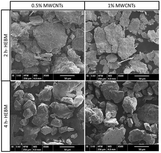
Figure 5.
SEM morphological evolution of MWCNT composite powders after 2 h and 4 h of HEBM.
Figure 6 shows the particle size distribution obtained for both reinforcement percentages after 2 h and 4 h of HEBM. After the initial two hours, most of the measured particles of 0.5 wt.% MWCNT composite powders are in the 40–100 μm range, whereas for the 1 wt.% MWCNTs, most particles are in the 40–80 μm range. Upon completion of the total milling time, the percentage of particles with sizes of 40–60 μm is greatly increased for 1% MWCNT, whereas for the mixture with 0.5% MWCNT, the increase is observed in the range between 120 and 140 μm. The computed average particle size for 1 wt.% MWCNT composite is close to 63 μm after 2 h and 54 μm after 4 h milling time. In the case of 0.5 wt.% composites, the average particle size is 83 μm at 2 h and 72 μm at the end of the milling process. This difference can be attributed to two simultaneous effects of MWCNTs. On the one hand, nanotubes act as a process control agent by attaching to the surface of the particles, limiting cold welding and subsequently favouring more intense plastic deformation of the particles. On the other hand, MWCNTs are incorporated into the particles, producing a harder surface after each impact from the milling media, therefore increasing the brittleness of the particles [32,39] (p. 4, p. 7) With the increasing content of MWCNTs, the effect is maximized, leading to lower average particle sizes [29] (p. 3).
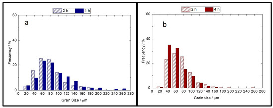
Figure 6.
Particle size distribution histograms determined from SEM measurements of AA7075-MWCNT composite particles after 2 h and 4 h of HEBM: (a) 0.5 wt.% MWCNTs; (b) 1 wt.% MWCNTs.
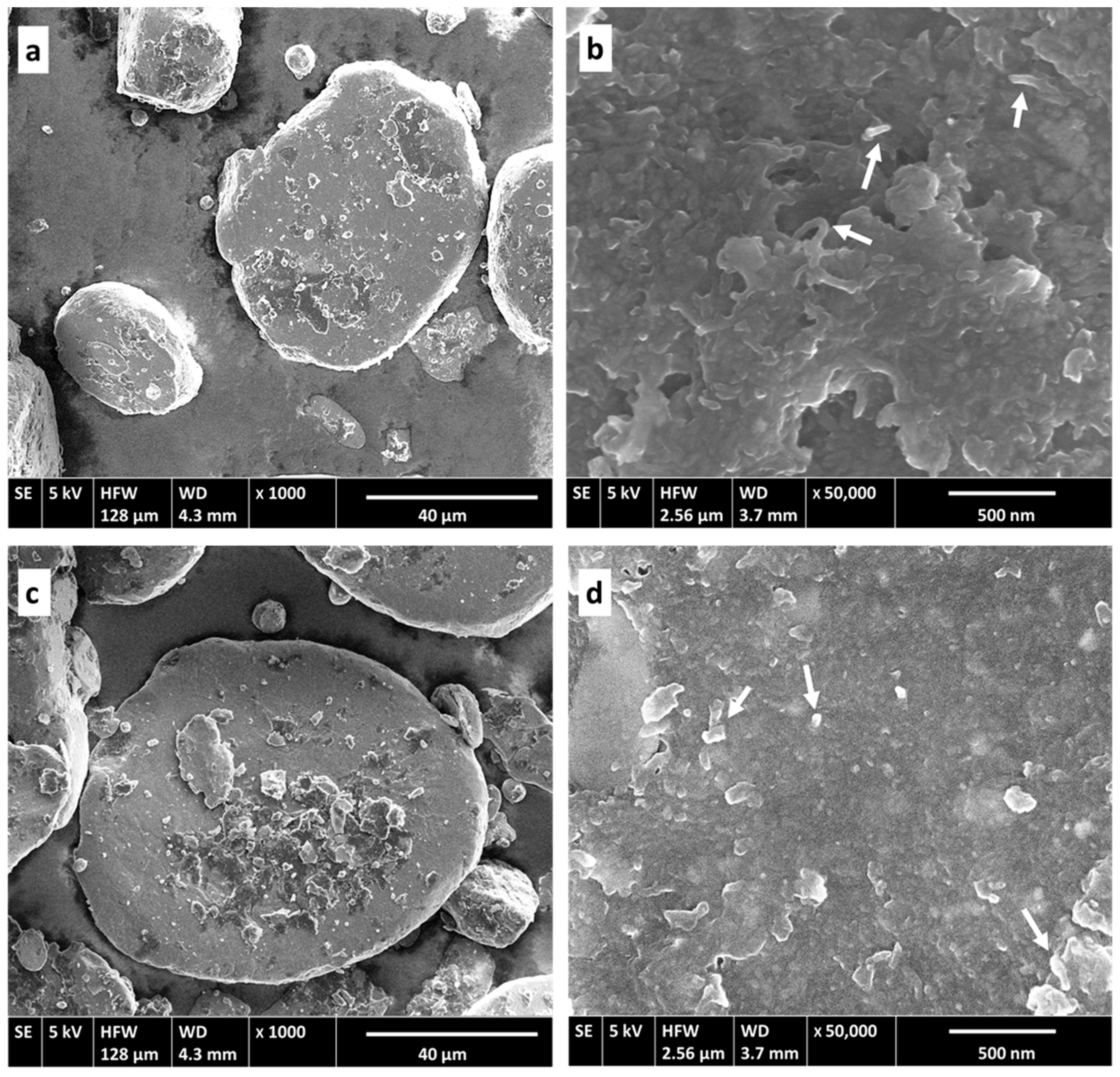
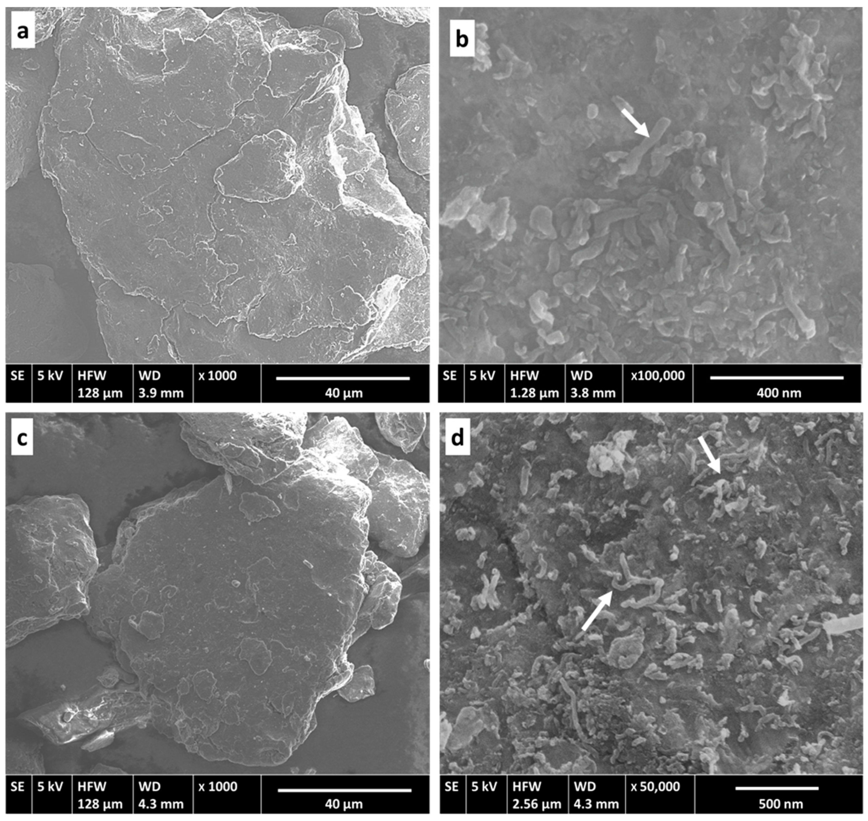
The high-impact energy of this route also helps to improve the dispersion of reinforcements into the matrix. In the initial stages, the bundles of MWCNTs are gradually disentangled, separated and dispersed into AA7075 powders. We observed that after milling for 2 h, the clusters adhere to and extend very uniformly on the surface of the AA7075 particles, forming a thin and homogeneous layer in which only a few tubules can be individually differentiated. With milling time increased to 4 h, the surfaces of the particles present a very smooth appearance, and almost no nanotubes can be observed on the surface, as shown in the SEM images in Figure 7. Therefore, after this amount of milling time, it is clear that the nanotubes are already embedded into the matrix. A mechanism for this integration was previously proposed for Al matrix composites [22] (p. 2). In the initial stage, AA7075 powders had a spherical shape, and MWCNT clusters tended to accumulate in the wells between particles. After a short ball milling time, bundles of nanotubes extended over and adhered to the soft surface of the particles. Under the continuous high-energy impacts, clusters are broken down by shearing forces at the same time that particles are being deformed into flakes, creating flat surfaces that can provide more sites for the adhesion of the tubules. Due to the cold welding of particles between them to create coarse and irregular particles, MWCNTs are progressively trapped inside the powders. Fracturing creates new surfaces, and the process can continue until the particles become hard and the adhesion of new nanotubes is finalized. The combination of a high ball-to-powder weight ratio, high rotational speeds in the attritor mill and the efficiency of the cycle procedure followed allow for dispersion and integration of the nanotubes to be achieved more quickly than reported by other researchers [11,24] (p. 1, p. 3). No evident differences are observed between the dispersion of 0.5% and 1 wt.% MWCNTs.
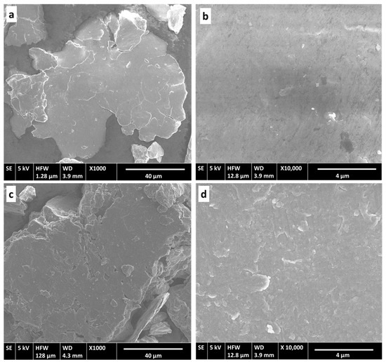
Figure 7.
SEM micrographs of AA7075-MWCNT composite particles obtained after 4 h of HEBM showing the good integration of MWCNs into the 7075 matrix: (a,b) 0.5 wt.% MWCNTs; (c,d) 1 wt.% MWCNTs.
3.2.2. Low-Energy Ball Milling (LEBM) Route
This strategy is designed to achieve correct dispersion without introducing severe damage to the nanotubes during the milling process. Therefore, pre-alloyed AA7075 powders and MWCNTs are introduced in the attritor mill, and milling is carried out for 4 h in 1 min cycles with the rotation speed varying from 300 rpm (48 s) to 200 rpm (12 s). Powder samples were extracted for analysis after 2 h and 4 h of milling.
Figure 8 shows SEM micrographs of the powder samples taken in the middle and at the end of the milling time, demonstrating that the particles are flattened due to ball impacts, but their rounded shape proves that cold welding and fragmentation to form more equiaxed particles did not occur extensively. This is an indication that the energy involved in the milling process was not sufficient. In these images, it is also evident that the MWCNTs are agglomerated in certain areas on the surface of the AA7075 particles (Figure 8a,c). At a higher magnification (Figure 8b,d), the clusters seem to be attached to the surface, but integration into the particles was not achieved. As a consequence of the poor dispersion of the reinforcements for both wt.% studied, this milling strategy was proven to be inadequate and was therefore discarded, so the results of the other analyses carried out on these samples are not presented in this paper.

Figure 8.
SEM micrographs of AA7075 + 1%-MWCNTs mixed with the LEBM method after different mill times: (a,b) 2 h; (c,d) 4 h.
3.2.3. High + Low-Energy Milling (H + LEBM) Route
This milling strategy was used in an attempt to obtain a material with a heterogeneous structure that would allow us to achieve an adequate combination of resistance and ductility. This is a line of research that is receiving a lot of attention, and there have recently been several reports on superior combinations of mechanical properties in metals, alloys and composites that are processed to have different heterogeneous microstructures but with the common feature of considerable difference in strength between different domains [41,42].
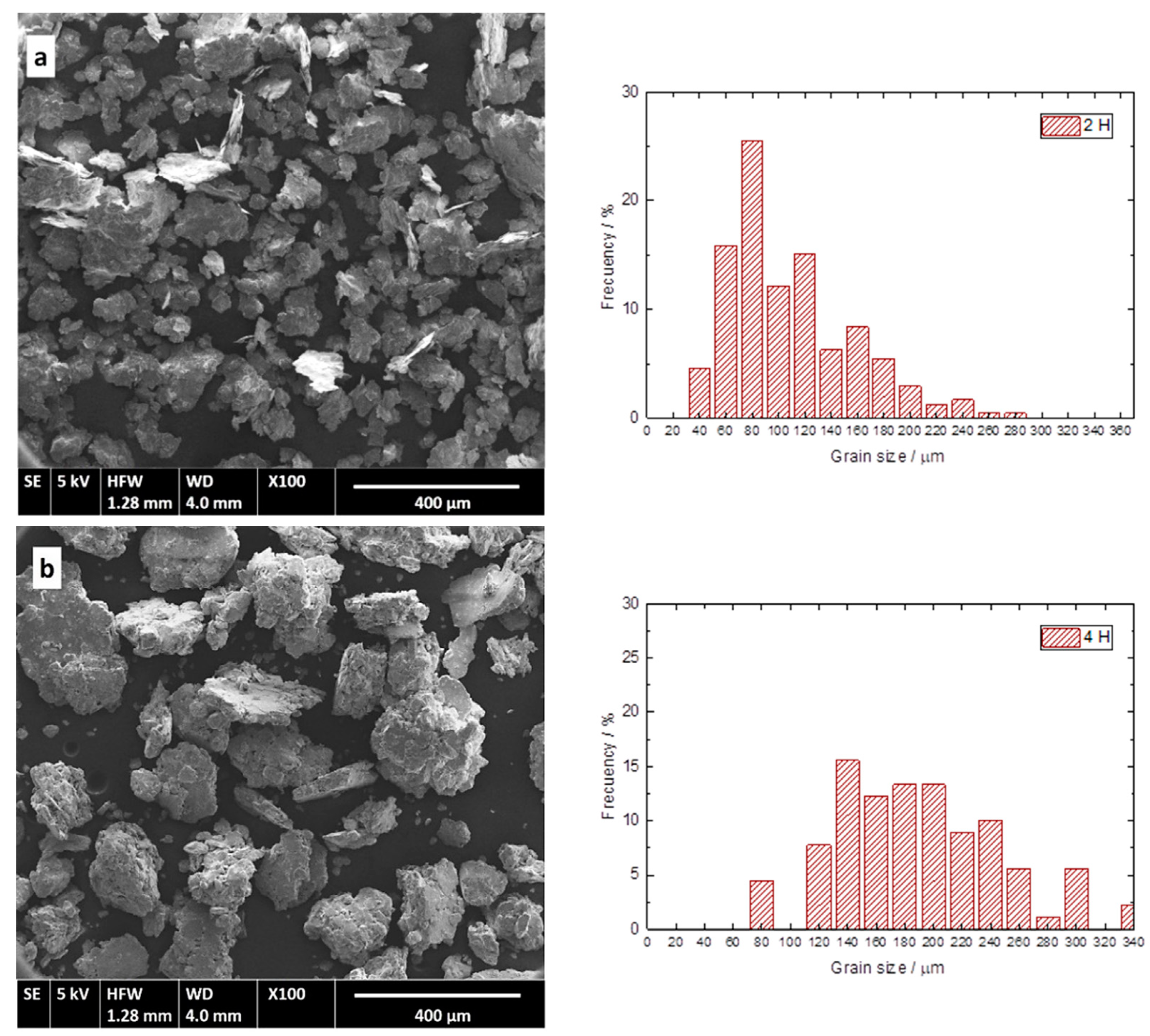
The applied process involves two milling stages. During the first stage, the AA7075 powders were milled via HEBM for 4 h, following the cycling process previously described, varying in speed between 1300 rpm and 1000 rpm, in order to obtain a fine-grained and strain-hardened structure. In the second stage, MWCNTs are added to the mill and grinded with the powders for a further 2 h in a low speed, low energy process (300/200 rpm) to promote the dispersion of the nanotubes. The assumption is that the delayed addition of the MWCNTs to the matrix could provide reinforcement-rich and lean regions, ultimately producing a heterostructured matrix. Samples were extracted at 2 h, 4 h and 6 h. Figure 9 shows the morphological changes of AA7075 particles during the high-energy milling stage without MWCNT addition during the H + LEBM route. The corresponding particle size distribution is presented for each case. After 2 h, most of the particles had a size between 60 and 120 μm, with an average size of 100 μm. This grain size is indicative of the predominance of cold welding in these early stages of milling. After 4 h of HEBM, the particle size distribution is clearly broadened, showing a profile very different from that obtained in the HEBM with MWCNTs added at the beginning of the process. In this case, most of the particles are between 120 and 260 μm, with an average size of 185 μm. The final particle morphology indicates that the cold-welding process continues to be predominant, giving rise to thicker particles with a multilayer structure by welding individual flakes with no preferred orientation, therefore causing an equiaxial morphology.
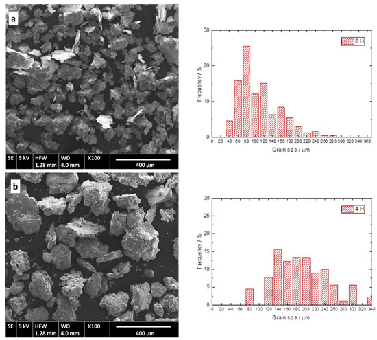
Figure 9.
SEM micrographs of AA7075 powders after milling in the first stage of the H + LEBM route with the corresponding particle size distribution: (a) 2 h of milling; (b) 4 h of HEBM without addition of MWCNTs.
When examining the particles of the samples extracted after the addition of MWCNTs and further milling at low speed for 2 h (total milling process: 6 h), a clear reduction in the dimensions of the particles for both percentages of MWCNTs can be observed (Figure 10).
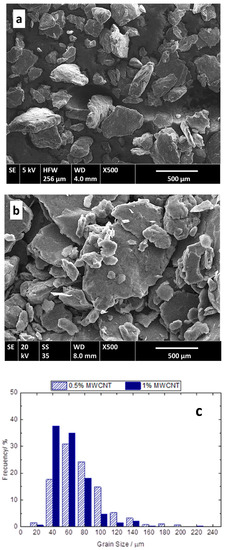
Figure 10.
SEM micrographs of AA7075-MWCNT composites after completing the H + LEBM route (6 h total milling): (a) 1 wt.% MWCNTs; (b) 0.5 wt.% MWCNTs; (c) particle size distribution for both MWCNT content levels.
This is due to the fracture process derived from the loss of ductility and increased hardness of the particles, together with the nanotubes, which seems to produce a cutting effect on the aluminium particles. In the case of 1 wt.% MWCNT composites, most of particles are 40–80 μm in size, with an average diameter of 52 μm. The particle size distribution is slightly more homogenous for the composite with the addition of 0.5 wt.% nanotubes, with most being 40–100 μm in size, with an average size of 66 µm. Additionally, the morphology of the particles is less irregular than in the previous stage.
These results indicate that the addition of MWCNTs in the last milling stage limits cold welding and favours the fracture process by increasing the hardness and reducing the ductility of the particles, helping to reduce the final size of powders. Observing data summarized in Table 3, which show the average particle sizes measured after the two strategies involving a high-energy stage, it becomes evident that there is no significant difference in the final size of the AA7075 particles for the two routes analysed. Another consequence to be drawn from these results is that 1 wt.% MWCNT composites show a greater reduction in particle size, regardless of the milling route followed.
Table 3.
Average particle size (in μm) of the powders milled through different routes and with different MWCNT percentages.
The effect of this H + LEBM milling strategy on the dispersion of the nanotubes is presented in Figure 11. SEM microstructures of the composite powders with both nanotube content levels indicate that the bundles were efficiently dispersed, and no agglomerations can be observed, unlike with the LEBM method. This suggests that although the milling time was shorter, the hardness acquired by the AA7075 particles in the previous high-energy stage helps in the dispersion of the nanotubes.

Figure 11.
SEM micrographs of 7075-MWCNT composite powders after the completion of the H + LEBM strategy: (a,b) 0.5 wt.% MWCNTs; (c,d) 1 wt.% MWCNTs.
Detailed observations of the particle surfaces show that most MWCNTs are uniformly distributed over the surface of the powders (Figure 11b,d), although the integration of the particles has not been complete and groups of tubules can be observed on some surfaces, especially in the 1 wt.% reinforcement composite (Figure 11d).
These results seem to indicate that the H + LEBM method allows for the correct dispersion of nanotubes, reducing the breakage and deterioration thereof due to the MWCNT addition being carried out when the 7075 particles had already undergone a significant degree of hardening. Under these conditions, we are likely to obtain a heterogeneous “core-shell” type structure wherein the MWCNTs are concentrated in a crust around the pre-alloyed powder particles without undergoing excessive deterioration. The subsequent consolidation of these particles by hot extrusion will make it possible to demonstrate whether this heterogeneous structure leads to improvements in the properties of the composite material. This research will be conducted in a future study.
3.3. Effect of Milling Conditions on Average Crystallite Size (ACS) and Lattice Strain (LS)
XRD was used to evaluate the effect of mechanical milling on the crystallite size and lattice strain of the aluminium matrix particles and to detect the possible presence of new phases formed by reactions between the MWCNTs and the aluminium of the matrix. As previously explained, only the results of the two strategies that proved to be efficient for nanotube dispersion are presented. The profiles of all Bragg reflections are broadened; this is related to the reduction in crystallite size and to the important lattice strain introduced by milling.
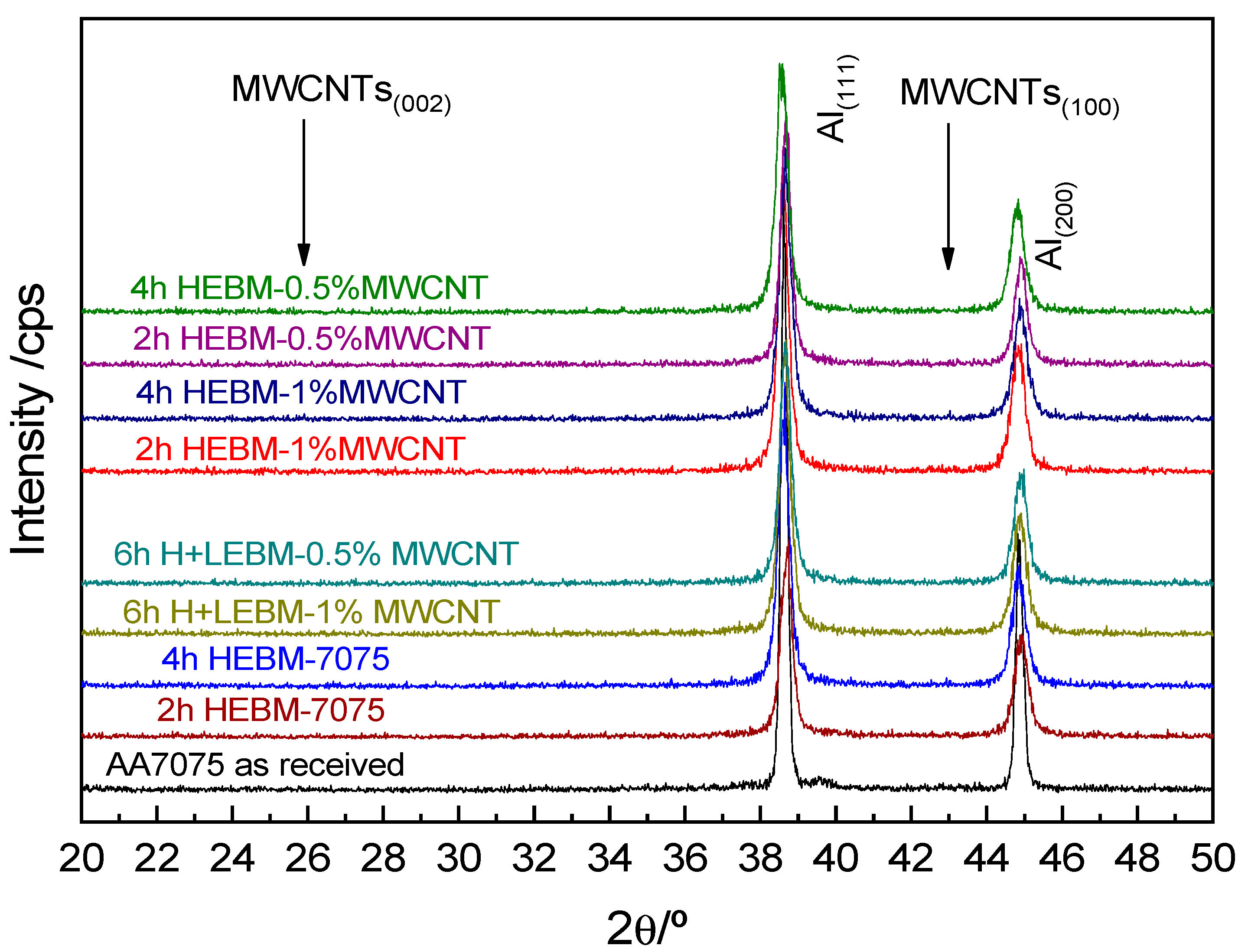
Figure 12 shows XRD diffractograms of AA7075-MWCNT composite powders with different MWCNT percentages milled through two different routes (HEBM and H + LEBM) compared to as-received AA7075 powders. All XRD patterns show five major peaks corresponding to the FCC phase of Al. In Figure 12, only the region between 20 and 50 2θ degrees of the XRD patterns is shown. This enlargement allows for better visualization of the two most intense peaks of aluminium, as well as the regions close to 26° and 43°, where the two most intense peaks attributed to the carbon nanotubes should appear [43,44]. No peak is detected that could correspond to the formation of Al4C3 during ball milling (peaks between 31–37°). Many researchers [17,28] (p. 2, p. 3) have reported the formation of Al4C3 during the manufacture of AlMC by metallurgy processing methods. The precipitation of aluminium carbide can occur as a consequence of the temperature reached during milling or the creation of defect sites and open ends in CNTs that favour their nucleation at temperatures below the aluminium melting point. The absence of peaks related to MWCNTs and peaks corresponding to any intermetallic phase are ascribed to the low amount of MWCNTs used and the fact that the filtered X-ray is limited in its detection of phases that account for less than 2% volume [45].
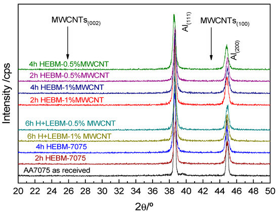
Figure 12.
XRD diffractograms of AA7075-MWCNT composite powders with different MWCNT percentages milled through different routes compared to as-received AA7075 powders.
It is well known that during high-energy ball milling, the impact and shear forces of the milling media induce the formation of a large amount of linear defects, such as dislocations and stacking faults, which result in the formation of high-dislocation-density regions in the grains piling up on the grain boundaries or irregular clusters in the grains [23,46,47] (p. 2). As a result of these microstructural changes, the profiles of all Bragg reflections are broadened; this is related to the reduction in crystallite size and to the important lattice strain introduced by milling. To analyse these effects, the highest-intensity peak was selected, that is, the peak of Al (111).
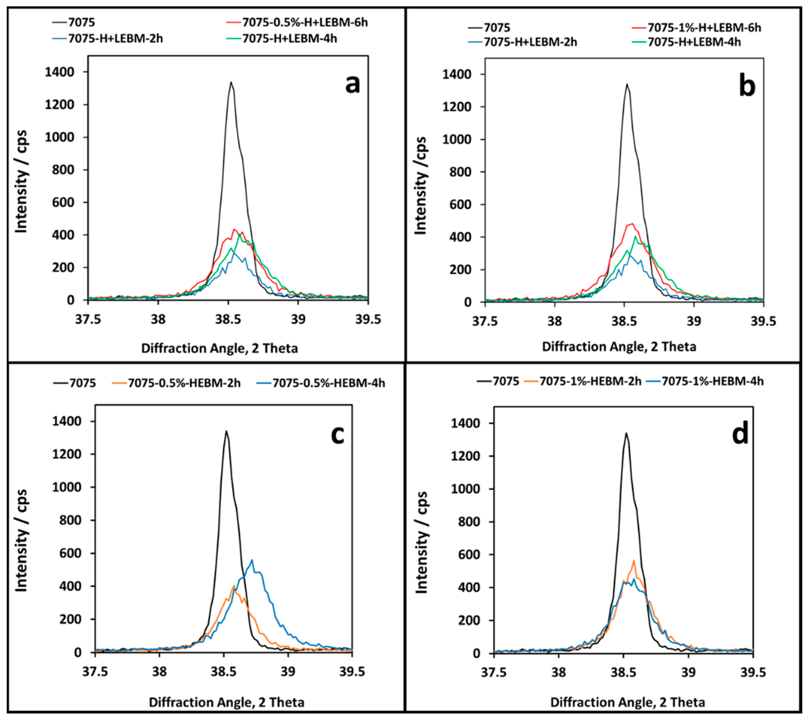
Figure 13 shows an enlarged view of the Al (111) peak corresponding to 7075 particles in the as-received (AR) condition and its evolution with milling time following the different milling routes and with different concentrations of MWCNTs. A broadening of the full width at half maximum (βhkl) and a decrease in peak intensity can be observed for both methods and MWCNT percentages, indicating structural changes with reduced crystallite size, as well as microstrain in the deformed powder particles [48,49]. As the H + LEBM route samples extracted at 2 h and 4 h correspond to AA7075 particles milled at high speed, the corresponding peaks are identical in Figure 13a,b.
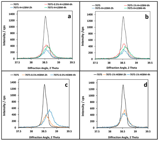
Figure 13.
XRD patterns for AA7075-MWCNT powders with different MWCNT percentages milled following different routes. Broadening and shift in the Al (111) peak is shown for: (a) H + LEBM and 0.5 wt.% MWCNTs; (b) H + LEBM and 1 wt.% MWCNTs; (c) HEBM and 0.5 wt.% MWCNTs; (d) HEBM and 1 wt.% MWCNTs.
According to these figures, the change in milling strategy does not produce evident changes in the evolution of the nanocrystalline structure of the samples, which seems to reach similar values under the two conditions, i.e., with MWCNTs added at the beginning of the milling process and with their addition after the HEBM stage. Similarly, the variation in the percentage of reinforcements does not produce a significant change in the broadening and the decrease in the maximum intensity of the Al (111) peak. This observation is in agreement with those reported by other researchers [50].
Samples of 0.5 wt.% MWCNT composites obtained following the HEBM route show a significant difference in the evolution of the Al (111) peak, with a displacement of the peak towards higher diffraction angles after 4 h of high-energy ball milling (Figure 13c). No clear explanation can be proposed for this phenomenon because it is not present in the 1 wt.% MWCNT composite samples. Several authors previously reported a displacement in the position of the XRD aluminium peaks towards lower diffraction angles [51] or towards higher values [45] (p. 17) as results of high-energy milling for different aluminium composites. Different reasons for this displacement have been suggested [45,52] (p. 17), such as the dissolution of minor alloying elements, the effect of impurities and reinforcement particles on the strain accumulation into the lattice of the aluminium matrix or residual strain (macrostrain) due to a change in the lattice parameters of the aluminium matrix during milling.
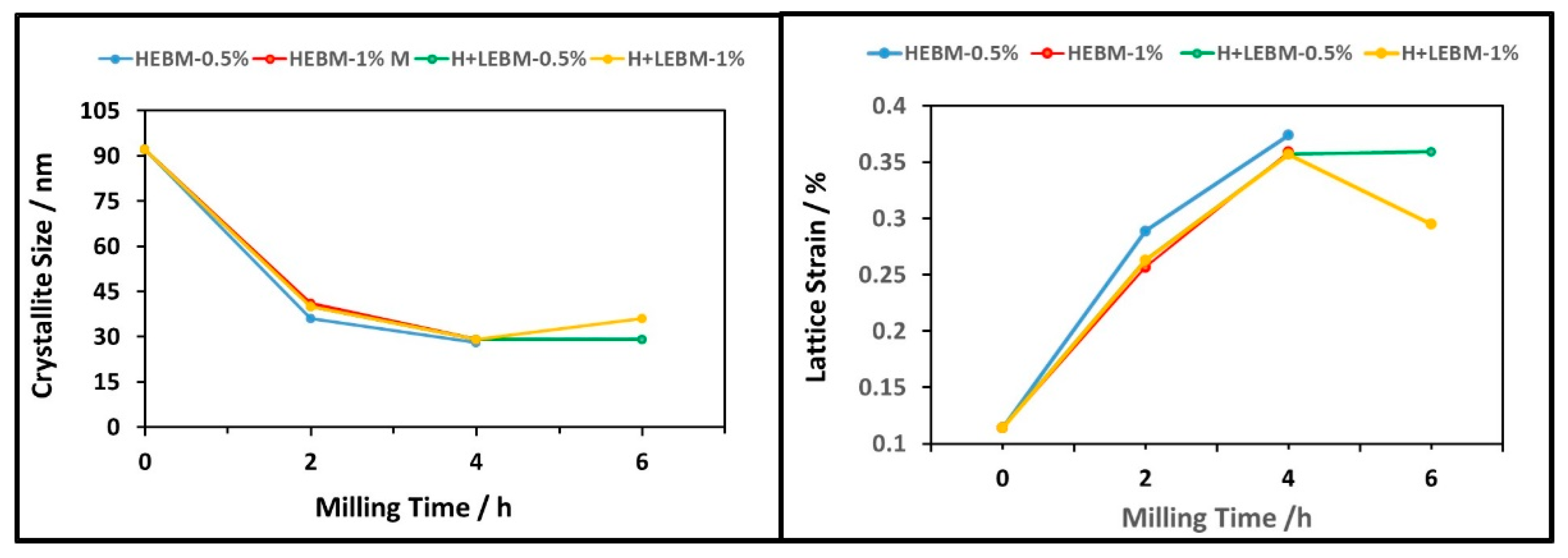
In order to better compare the results obtained with the two milling routes for both wt.% MWCNTs, the variation in crystalline size and lattice strain of composite powders, as a function of milling time, are presented in Figure 14. The crystallite size and lattice strain were estimated using Scherrer’s formula and Equation (2) on the peak (111). A detailed analysis of these graphs allows us to draw several conclusions.
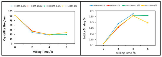
Figure 14.
Variation in crystallite size and lattice strain in composite powders as a function of time for different milling routes.
Firstly, the most significant change in crystallite size, as well as in the percentage of microdeformations, occurs after the first 2 h of milling, regardless of the route followed, the presence or absence of nanotubes in the high-energy milling process and their percentage. This intense decrease in crystallite size was achieved at significantly shorter times than those reported by other researchers [48] (p. 17) due to the higher energy involved in the milling process followed in this work, which was performed with the same BPR (10:1) in a cycle operation procedure at higher rotary speeds.
The average crystallite size of the as-received 7075 powders decreases from 92 nm to a value close to 40 nm after 2 h of HEBM with and without 1% of MWCNT, representing a reduction of 43%. For the mixture with 0.5% of MWCNTs, the reduction is slightly smaller, with an average crystallite size of 36 nm. The lattice strain of the 7075 powders also increases from 0.114% in the starting powders (without milling) to values close to 0.26%, except for the HEBM route with 0.5 wt.% MWCNTs, for which the value of the strain is slightly higher, i.e., 0.29%.
The high energy of the ball impacts during this first stage of milling, where the 7075 is still ductile and the lattice strain is low, induces severe plastic deformation, creating a large number of dislocations and other defects, such as stacking faults [17] (p. 2). Dislocations are rearranged to a lower energy state, and low-angle sub-boundaries are formed. As the generation of dislocations continues, low-angle sub-boundaries transform into high-angle boundaries and become grains at the nanoscale. These trends have also been observed by other researchers [28,46] (p. 3, p. 17). As a consequence of strain hardening, the crystallite refinement produced in the next two milling hours is far less remarkable. The declining rate of crystallite reduction from 2 to 4 h (HEBM) or 6 h (H + LBM) of milling is accompanied by a similar increase rate in the lattice strain, as shown in Figure 14.
The second remarkable observation is that there is no significant difference in the final crystal size or lattice strain values when comparing both routes for 0.5% MWCNTs. For the conditions used in this study, the results reveal that for 0.5 wt.% MWCNTs, regardless of the route followed, the crystallite size of the as-received powders (92 nm) decreases with milling time to a steady value of ~28 nm. The lattice strain (0.114%) also increases to a steady state close to 0.36%.
However, for the highest nanotube concentration (1%), a difference in crystallite size and lattice strain is observed at the end of the two routes. The H + LEBM route leads to the largest final crystallite size (36 nm) and, consequently, to the lowest level of deformation (0.30%). It should be noted that the differences between the two routes are not significant. At the end of the HEBM route, the crystal size is 29 nm, and the lattice strain is 0.36%.
In summary, for the conditions tested in this study (high energy, short time and low percentage of nanotubes), there are no significant differences in crystal size or in strain lattice values when comparing either routes or the influence of nanotube contents.
3.4. Effect of Cyclic Ball Milling Process on MWCNTs
Raman spectroscopy was used to appraise the degradation induced in the structure of MWCNTs during the mechanical milling step.
Raman spectroscopy has emerged as an important tool for the characterization of carbon nanomaterials on account of its sensitivity to even slight changes in highly symmetric covalent bonds. Since the first observation of MWNTCs in 1991 by Iijima [53], this technique has been used to characterize the synthesis and purification processes of carbon nanotubes and to study their properties. It has proven to be a powerful tool for the characterization of single-walled carbon nanotubes (SWNTs), supplying information about purity, tube alignment and defects. In recent years, MWCNTs have also been characterized by Raman spectroscopy, although interpretation is often more difficult, usually based on the well-established results obtained for SWCNTs.
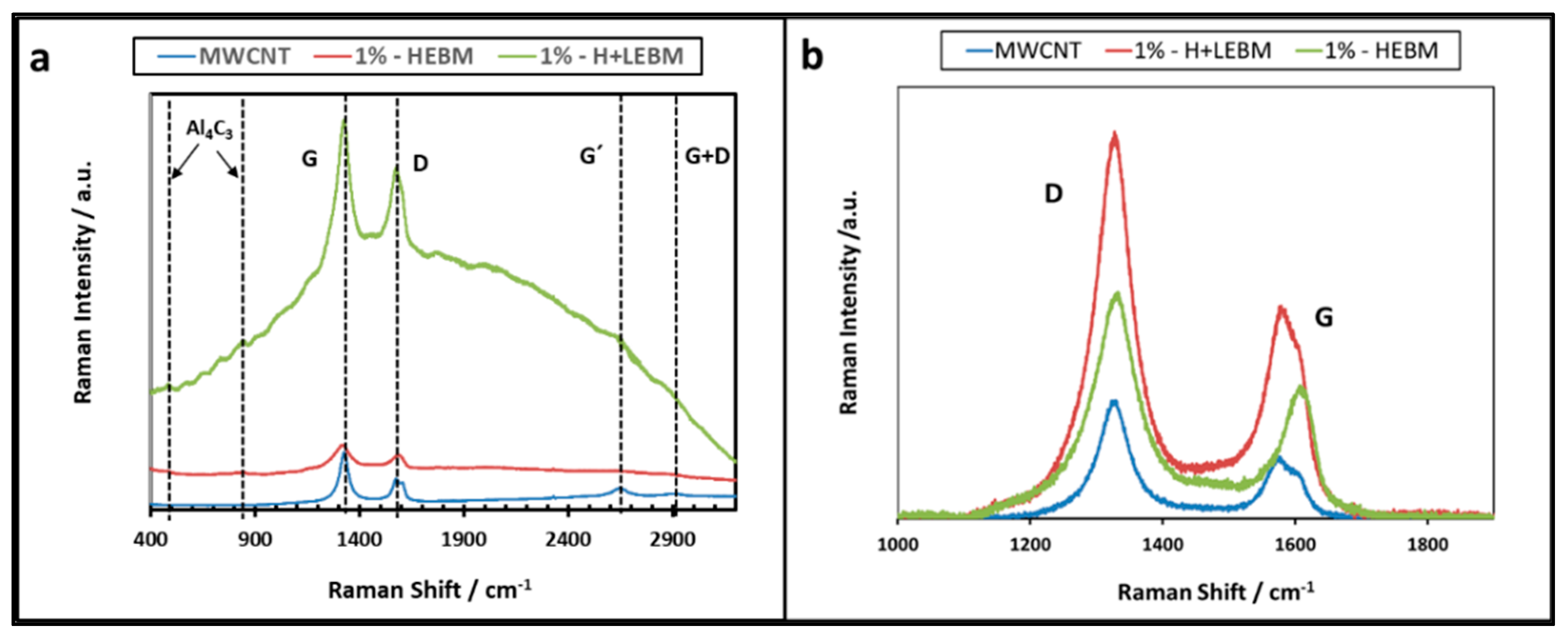
Figure 15a shows the Raman spectra of the AA7075 composite reinforced with 1 wt.% MWCNTs obtained by the two proposed milling methods, HEBM and H + LEBM, compared to the as-received MWCNTs. The spectra were obtained under the same experimental conditions (HeNe laser, 632.8 nm, 20 scans and exposure time of 15 s). Similar results were obtained for the 0.5 wt.% composite with both strategies.
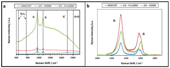
Figure 15.
Raman spectra of as-received MWCNTs and the AA7075-1 wt.% MWCNT composite obtained by H + LEBM and HEBM routes. (a) Frequency range from 30 to 3500 cm−1, 20 scans and exposure time of 15 s; (b) frequency range from 1000 to 2000 cm−1, 10 scans to 10 and exposure time of 5 s.
The Raman spectra of MWCNTs show D and G bands due to sp2 sites [54], as well as the G’ band, which is attributed to the overtone of the D band. The G band corresponds to the tangential vibrations of the C-C sp2 bond atoms and therefore appears wider and smaller for poorly structured and defect-containing nanotubes. This band shows two components: the lower-frequency component associated with vibrations along the circumferential direction, (G−), which is therefore diameter-dependent; and the higher-frequency component, (G+), which is attributed to vibrations along G direction of the nanotube axis [55]. In this work, the G+ band was detected at 1572 cm−1, and the G− band was located at 1604 cm−1.
On the other hand, in MWCNTs, the D− band is attributed to lattice defects, such as kinks, heteroatoms and vacancies, as well as finite or nanosized graphitic planes in rings [56].
As shown in Figure 15a, the important background due to the fluorescence of the sample corresponding to the H + LEBM route makes it difficult to compare the shape and intensity of the D and G bands between the three samples. To avoid this effect, new Raman spectra were collected in the frequency range between 1000 and 2000 cm−1 (Figure 15b) by performing 10 scans with 5 s exposure time to reduce the excitation time. Table 4 shows the position of D and G bands and the ID/IG ratio computed after background removal. The addition of MWCNTs into the AA7075 matrix via milling processes causes changes in the spectra, such as a clear change in the intensity of the D and G peaks and a slight shift to higher frequencies of the G and D bands [22] (p. 2). These effects, together with the broadening of both peaks, indicate a notorious increase in the defects and amorphization of the CNTs.
Table 4.
D-band and G-band peaks, as well as ID/IG ratio, for as-received MWCNTs and 7075-1 wt.% MWCNT composites obtained by the two proposed milling routes.
Despite the similarities, there are differences between the spectra of the two samples that should be pointed out. The displacement towards higher frequencies of the G band is greater for composites obtained by the HEBM route (1607 cm−1 vs. 1578 cm−1 for the H + LEBM route). On the other hand, the displacement of the D band towards higher frequencies is the same. Another parameter usually used to assess this damage to nanotubes is the change in the two band intensities, which is quantified by the ID/IG ratio. As expected, the ratio obtained for both routes is higher than the value for the as-received MWCNTs, and it is almost the same for both routes. All these data confirm that the degradation of MWCNTs is reduced by the strategy in which these reinforcements are incorporated into previously hardened matrix powders through a low-energy milling stage.
Finally, the spectra of both 7075-1 wt.% MWCNT composites (Figure 15a) show two small peaks at 488 cm−1 and 840 cm−1, as previously reported by Xu et al. [57], corresponding to Al4C3. As previously mentioned, partial damage to the walls of MWCNTs during milling generates regions for the reaction of Al and C that facilitate the formation of Al4C3. The slight shift of several cm−1 between the reported values and those measured in this work can be attributed to crystal defects of the Al4C3 grown over the damaged MWCNTs. This verifies the formation of this carbide, although XRD spectra do not detect the presence of aluminium carbide, probably because the amount is too small to be detected, given the resolution of this technique.
3.5. Nanoindentation Results
The interaction between the Al matrix and CNTs and the dispersion of CNTs themselves are the main issues directly related to the mechanical properties of the composite. In our study, the formation of covalent bonds (Al4C3) at the interface between the Al matrix and CNTs was confirmed for 7075-1 wt.% MWCNTs obtained via both routes. The most relevant aspects related to the effect of MWCNTs on the mechanical resistance of composites are their proportion, their adequate dispersion and the interaction between the matrix and the nanotubes. Although data confirmed the formation of covalent bonds (Al4C3) at the Al-C interface in composites containing 1 wt.% MWCNTs, their presence is considered very limited, so an analysis of the results shown below was performed based on the % and distribution of the reinforcements.
Table 5 presents the hardness (H) and elastic modulus (E) values obtained through nanoindentation tests of powder composites obtained by different milling routes and for the two concentrations of nanotubes. These values can be compared with the results obtained for the AA7075 pre-alloyed powders milled under high energy without nanotubes. The indentation depth was established at 500 nm to ensure that the indented area was much smaller than the tested powder particles.
Table 5.
Hardness and Young’s modulus values.
The nanoindentation results show that whereas the hardness values remain very similar in all samples, the addition of 0.5 wt.% MWCNTs to the composites obtained through the two milling strategies produces a clear increase in the value of E. However, this increase is not as significant in the composites with 1 wt.% MWCNTs, especially in the case of the H + LEBM route, in which a decrease in the modulus of elasticity is measured.
There is a lack of literature data on elastic modulus because most research has focused on improving the yield/tensile strength. There is a large scatter in the Ecomposite/Emetal-matrix ratio, especially at low CNT volume fractions [58,59,60]. For example, Gowda and Girish [61] performed nanoindentation characterization to measure the hardness and elastic modulus properties of Al reinforced with B4C particulates and carbon nanotubes (CNT) synthesized by powder metallurgy. Their results clearly reveal that Young’s modulus decreases with the addition of B4C to the aluminium matrix but increased with the addition of CNT up to 1%, beyond which point it decreased. Similar results were obtained by U. Abdullahi et al. [62] when studying the influence of different percentages of nanotubes (1, 1.5, 2.0 and 2.5 wt.% CNT) on aluminium nanocomposites (Al-CNT). Their results obtained using nanoindentation and Vickers microhardness techniques show that hardness increased with the increased CNT percentage up to 2 wt.%.
Esawi et al. observed a similar trend [32] (p. 4) in their study using the Vickers test to evaluate microhardness and nanoindentation measurements for determination of Young´s module on aluminium matrix nanocomposites with 0.5, 1, 2 and 5 wt.% CNTs. The maximum hardness value was observed at 0.5 wt.% CNTs, and the maximum value of Young’s modulus was measured in composites with 2 wt.% CNTs. They attributed these results to the tendency of CNTs to agglomerate at high-volume fractions due to the large aspect ratio of the CNTs used in their study.
In previous studies, it was verified that with a certain percentage of CNTs, it is difficult to achieve their adequate dispersion in the matrix. When the CNT clusters are not well-infiltrated with the metal matrix, load transfer to CNT clusters is very small, and an elastic response dominates the matrix. Therefore, a descent in mechanical properties is observed.
These observations are in agreement with our results, wherein the lower value corresponds to a condition where a higher concentration of nanotubes is milled for only two hours under low energy. This may also be the cause of the low E values obtained in the 1wt.% MWCNT composite samples manufactured by the H + LEBM route, in which nanotubes are mixed for only two hours under low-speed milling. These conditions of energy seem to be insufficient to achieve a complete dispersion and integration of nanotubes in the matrix, leading to a less rigid composite.
4. Conclusions
In the search for an efficient and economical process that can be implemented in industry for the manufacture of profiles of AA7075 matrix composites reinforced with MWCNTs, a powder metallurgical process was developed with a mechanical milling stage followed by a hot extrusion stage.
In this paper, we presented the results obtained in a study of three mechanical ball milling strategies proposed with the aim of achieving effective dispersion of 0.5 wt.% and 1 wt.% MWCNTs in the matrix powders.
- -
- The high-energy ball milling route (HEBM) strategy achieves good dispersion and integration of the nanotubes in the AA7075 particles for the two percentages of reinforcements tested after 4 h of milling. Therefore, the cyclic variation of the speed (1 min cycles with a 48 s stage at 1300 rpm and a 12 s stage at 1000 rpm) allows for a reduction in the milling time, obtaining average particle sizes of 72 µm for 0.5 wt.% and 54 µm for 1 wt.% MWCNTs.
- -
- The low-energy ball milling route (LEBM) does not effectively disaggregate the MWCNT bundles and does not achieve adequate dispersion and incorporation into the AA7075 particles in the considered milling time (4 h in 1 min cycles varying rotation speed from 300 rpm for 48 s to 200 rpm for 12 s). These processes could be improved by notably increasing the milling time, but this would make its industrial implementation difficult. Thus, this strategy was discarded.
- -
- The high + low-energy (H + LEBM) strategy (4 h HEBM of AA7075 powders with no nanotubes + 2 h LEBM with MWCNTs) allowed for the adequate dispersion of the nanotubes, achieving their integration on the surface of the powders. In subsequent work, we will tested whether this “core-shell” structure can lead, after extrusion, to composites with heterogeneous microstructures and improved properties. The average particle size obtained via this route is 66 µm with 0.5 wt.% and 52 µm with 1 wt.% MWCNTs.
- -
- The nanoindentation technique makes it possible to verify that the highest E and H values are achieved in the samples with 0.5 wt.% MWCNTs produced by the H + LEBM milling route.
- -
- In the characterization carried out through Raman spectroscopy, the values of the ID/IG ratio determined form the spectra indicate that there is no significant difference in the damage induced in the MWCNTs in the two milling routes analysed. This is consistent with the fact that the stage that the two routes have in common is initial high-energy milling for 4 h, in which the maximum deformation of the powders and reinforcements occurs. It is significant to note that the difference in distortion detected in the MWCNTs in the as-received state is not relevant.
- -
- Moreover, the presence of a small amount of Al4C3 is detected in composites obtained from both routes due to the reaction of C with Al from the matrix.
- -
- After the performed XRD study, the average crystallite size obtained at the end of both HEBM and H + LEBM is similar (approximately 30 nm), representing a reduction of ~40% with respect to the as-received AA7075 powders. The most important crystallite size reduction takes place in the first two hours of milling, and the presence of nanotubes, at least in the proportions considered, seems to be irrelevant.
- -
- Based on the obtained results, especially those with respect to mechanical properties, it seems that the best option is to use 0.5% MWCNTs, regardless of the route followed.
Author Contributions
Conceptualization, I.F., G.P., M.J.C., M.C. and P.R.; data curation, I.F.; formal analysis, M.C., M.J.C. and P.R.; funding acquisition, G.P. and M.J.C.; investigation, I.F., G.P., M.J.C., M.C. and P.R.; methodology, I.F.; project administration, G.P.; supervision, G.P. and M.J.C.; writing—original draft, M.J.C.; writing—review and editing, G.P. and M.J.C. All authors have read and agreed to the published version of the manuscript.
Funding
This research was funded by the Ministry of Science, Innovation and Universities and the European Regional Development Funds (ERDF) (grant number: MAT2017-83825-C4-2-R).
Data Availability Statement
Not applicable.
Conflicts of Interest
The authors declare no conflict of interest.
References
- Koli, D.K.; Agnihotri, G.; Purohit, R. Advanced Aluminum Matrix Composites: The Critical Need of Automotive and Aerospace Engineering Fields. Mater. Today Proc. 2015, 2, 3032–3041. [Google Scholar] [CrossRef]
- Fogagnolo, J.B.; Velasco, F.; Robert, M.H.; Torralba, J.M. Effect of mechanical alloying on the morphology, microstructure and properties of aluminum matrix composite powders. Mater. Sci. Eng. 2003, A342, 131–143. [Google Scholar] [CrossRef]
- Zhao, N.; Nash, P.; Yang, X. The effect of mechanical alloying on SiC distribution and the properties of 6061 aluminum composite. J. Mater. Process. Technol. 2005, 170, 586–592. [Google Scholar] [CrossRef]
- Yao, X.; Zheng, Y.F.; Liang, J.M.; Zhang, D.L. Microstructures and tensile mechanical properties of an ultrafine grained AA6063-5 vol% SiC metal matrix nanocomposite synthesized by powder metallurgy. Mater. Sci. Eng. 2015, A648, 225–234. [Google Scholar] [CrossRef]
- Chen, C.-L.; Lin, C.-H. Effect of Y2O3 and TiC reinforcement particles on intermetallic formation and hardness of Al 6061 composites via mechanical alloying and sintering. Metall. Mater. Trans. A 2015, 46, 3687–3695. [Google Scholar] [CrossRef]
- Abreu, C.; Acuña, R.; Cristóbal, M.J.; Verdera, D.; Llovo, C. Friction Stir Processing Strategies to develop a surface layer composite on AA6061-T6. Mater. Manuf. Process. 2018, 33, 1133–1140. [Google Scholar]
- Acuña, R.; Cristóbal, M.J.; Abreu, C.; Cabeza, M. Microstructure and Wear Properties of Surface Composite Layer Produced by Friction Stir Processing (FSP) in AA2024-T351 Aluminum Alloy. Metall. Mater. Trans. A 2019, 50, 2860–2874. [Google Scholar] [CrossRef]
- Gandra, J.; Miranda, R.; Vila, P.; Velhinho, A.; Pamies, J.; Teixeira, A.V.; Pamiès Teixeira, J. Functionally Graded Materials Produced by friction stir processing. J. Mater. Process. Technol. 2011, 211, 1659–1668. [Google Scholar] [CrossRef]
- Feijoo, I.; Cabeza, M.; Merino, P.; Pena, G.; Rey, P. Age Hardening of Extruded AA 6005A Aluminum Alloy Powders. Materials 2019, 12, 2316. [Google Scholar] [CrossRef] [Green Version]
- Eatemadi, A.; Daraee, H.; Karimkhanloo, H.; Kouhi, M.; Zarghami, N.; Akbarzadeh, A.; Abasi, M.; Hanifehpour, Y.; Joo, S.W. Carbon nanotubes: Properties, synthesis, purification, and medical applications. Nanoscale Res. Lett. 2014, 9, 393. [Google Scholar] [CrossRef] [Green Version]
- Peng, T.; Chang, I. Mechanical alloying of multi-walled carbon nanotubes reinforced aluminum composite powder. Powder Technol. 2014, 266, 7–15. [Google Scholar] [CrossRef]
- Park, G.; Keum, D.H.; Lee, Y.H. Strengthening mechanisms in carbon nanotube-reinforced aluminum composites. Carbon 2015, 95, 690–698. [Google Scholar] [CrossRef]
- Li, Z.; Jiang, L.; Fan, G.; Xu, Y.; Zhang, D.; Chen, Z. Humphries, High volume fraction and uniform dispersion of carbon nanotubes in aluminium powders. Micro. Nan. Lett. 2010, 5, 379–381. [Google Scholar] [CrossRef]
- Cui, H.; Yan, X.; Monasterio, M.; Xing, F. Effects of various surfactants on the dispersion of MWCNTs–OH in aqueous solution. Nanomaterials 2017, 7, 262. [Google Scholar] [CrossRef] [Green Version]
- Guo, B.; Zhang, X.; Cen, X.; Chen, B.; Wang, X.; Song, M.; Ni, S.; Yi, J.; Shen, T.; Du, Y. Enhanced mechanical properties of aluminum based composites reinforced by chemically oxidized carbon nanotubes. Carbon 2018, 139, 459–471. [Google Scholar] [CrossRef]
- Nyanor, P.; Bahador, A.; El-Kady, O.A.; Umeda, J.; Kondoh, K.; Hassan, M.A. Improved ductility of spark plasma sintered aluminium-carbon nanotube composite through the addition of titanium carbide microparticles. Mater. Sci. Eng. A 2020, 795, 139959. [Google Scholar] [CrossRef]
- Mohammed, S.M.A.K.; Chen, D.L. Carbon Nanotube-Reinforced Aluminum Matrix Composites. Adv. Eng. Mater. 2020, 22, 12–27. [Google Scholar] [CrossRef]
- Choi, H.J.; Shin, J.H.; Min, B.H.; Park, J.S.; Bae, D.H. Reinforcing effects of carbon nanotubes in structural aluminum matrix nanocomposites. J. Mater. Res. 2009, 24, 2610–2616. [Google Scholar] [CrossRef]
- Deng, C.F.; Wang, D.Z.; Zhang, X.X.; Li, A.B. Processing and properties of carbon nanotubes reinforced aluminum composites. Mater. Sci. Eng. A 2007, 444, 138–145. [Google Scholar] [CrossRef]
- George, R.; Kashyap, K.T.; Rahul, R.; Yamdagni, S. Strengthening in carbon nanotube/aluminum (CNT/Al) composites. Scr. Mater. 2005, 53, 1159–1163. [Google Scholar] [CrossRef]
- Zhang, D.L. Processing of advanced materials using high-energy mechanical milling. Prog. Mater. Sci. 2004, 49, 537–560. [Google Scholar] [CrossRef]
- Poirier, D.; Gauvin, R.; Robin, A.L.D. Structural Characterization of a Mechanically Milled Carbon Nanotube/Aluminum. Mixture. Compos. A 2009, 40, 1482–1489. [Google Scholar] [CrossRef]
- Morsi, K.; Esawi, A. Effect of mechanical alloying time and carbon nanotube (CNT) content on the evolution of aluminum (Al)–CNT composite powders. J. Mater. Sci. 2007, 42, 4954–4959. [Google Scholar] [CrossRef]
- Liu, Z.Y.; Xu, S.J.; Xiao, B.L.; Xue, P.; Wang, W.G.; Ma, Z.Y. Effect of ball-milling time on mechanical properties of carbon nanotubes reinforced aluminum matrix composites. Compos. Part A Appl. Sci. Manuf. 2012, 43, 2161–2168. [Google Scholar] [CrossRef]
- Choi, H.J.; Shin, J.H.; Bae, D.H. The effect of milling conditions on microstructures and mechanical properties of Al/MWCNT composites. Compos. Part A Appl. Sci. Manuf. 2012, 43, 1061–1072. [Google Scholar] [CrossRef]
- Deng, C.; Zhang, X.X.; Wang, D.; Lin, Q.; Li, A.B. Preparation and Characterization of Carbon Nanotubes/Aluminum Matrix. Compos. Mater. Lett. 2007, 61, 1725–1728. [Google Scholar] [CrossRef]
- Wei, H.; Li, Z.; Xiong, D.B.; Tan, Z.; Fan, G.; Qin, Z.; Zhang, D. Towards Strong and Stiff Carbon Nanotube-Reinforced High-Strength Aluminum Alloy Composites Through a Micro-laminated Architecture Design. Scr. Mater. 2014, 75, 30–33. [Google Scholar] [CrossRef]
- Travessa, D.N.; Da Rocha, G.V.B.; Cardoso, K.R.; Lieblich, M. Carbon Nanotube-Reinforced Aluminum Matrix Composites Produced by High-Energy Ball Milling. J. Mater. Eng. Perform. 2017, 26, 2998–3006. [Google Scholar] [CrossRef]
- Uriza-Vega, E.; Carreño-Gallardo, C.; López-Meléndez, C.; Cuadros-Lugo, E.; Pérez-Bustamante, R.; Ledezma-Sillas, E.; Herrera-Ramirez, J.M. Mechanical Behavior of Multiwalled Carbon Nanotube Reinforced 7075 Aluminum Alloy Composites Prepared by Mechanical Milling and Hot Extrusion. Mater. Res. 2019, 22, e20180652. [Google Scholar] [CrossRef]
- Jagannatham, M.; Senthil Saravanan, M.S.; Sivaprasad, K.; Kumaresh Babu, S.P. Mechanical and Tribological Behavior of Multiwalled Carbon Nanotubes-Reinforced AA7075 Composites Prepared by Powder Metallurgy and Hot Extrusion. J. Mater. Eng. Perform. 2018, 27, 5675–5688. [Google Scholar] [CrossRef]
- Zhang, H.B.; Wang, B.; Zhang, Y.T.; Li, Y.; He, J.L.; Zhang, Y.F. Influence of aging treatment on the microstructure and mechanical properties of CNTs/7075 Al composites. J. Alloys Compd. 2020, 814, 152357. [Google Scholar] [CrossRef]
- Esawi, A.M.K.; Morsi, K.; Sayed, A.; Taher, M.; Lanka, S. Effect of carbon nanotube (CNT) content on the mechanical properties of CNT-reinforced aluminum composites. Compos. Sci. Technol. 2010, 70, 2237–2241. [Google Scholar]
- Cabeza, M.; Merino, P.; Rey, P.; Román, M. Development of a high wear resistance aluminium matrix nanoreinforced composite. Surf. Interface Anal. 2012, 44, 1005–1008. [Google Scholar] [CrossRef]
- Suryanarayana, C.; Norton, M.G. X-ray Diffraction: A Practical Approach; Plenum Press: New York, NY, USA, 1998. [Google Scholar]
- Srinivasan, R.; Yogamalar, N.R.; Joseyphus, R.J.; Bose, A.C. Estimation of lattice strain, stress, energy density and crystallite size of the spherical yttrium oxide nanoparticles. Funct. Mater. Lett. 2009, 2, 131–134. [Google Scholar] [CrossRef]
- Oliver, W.C.; Pharr, G.M. An improved technique for determining hardness and elastic modulus using load and displacement sensing indentation experiments. J. Mater. Res. 1992, 7, 1564–1583. [Google Scholar] [CrossRef]
- Salem, H.G.; El-Eskandarany, S.; Kandil, A.; Fattah, H.A. Bulk Behavior of Ball Milled AA2124 Nanostructured Powders Reinforced with TiC. J. Nanomater. 2009, 479185. [Google Scholar] [CrossRef] [Green Version]
- Molnárová, O.; Málek, P.; Lukáč, F.; Chráska, T. Spark Plasma Sintering of a Gas Atomized Al7075 Alloy: Microstructure and Properties. Materials 2016, 9, 1004. [Google Scholar] [CrossRef] [Green Version]
- Abdullah, M.P.; Zulkeplia, S.A. The Functionalization and Characterization of Multi-walled Carbon Nanotubes (MWCNTs). In AIP Conference Proceedings; AIP Publishing LLC: Melville, NY, USA, 2015; Volume 1678, p. 050033. [Google Scholar] [CrossRef]
- Atchudan, R.; Pandurangan, A.; Joo, J. Effects of Nanofillers on the Thermo-Mechanical Properties and Chemical Resistivity of Epoxy Nanocomposites. J. Nanosci. Nanotechnol. 2015, 15, 4255–4267. [Google Scholar] [CrossRef]
- Wua, X.; Zhu, Y. Heterogeneous materials: A new class of materials with unprecedented mechanical properties. Mater. Res. Lett. 2017, 5, 527–532. [Google Scholar] [CrossRef]
- Saba, F.; Nateq, B.; Sajjadi, S.A.; Zhang, F.; Heydari, S. The enhanced mechanical properties and strain-hardening capability of CNT/Al composites achieved by heterogeneous micro-laminated architecture. Compos. Commun. 2021, 27, 100861. [Google Scholar] [CrossRef]
- Esawi, A.M.K.; Morsi, K.; Sayed, A.; Gawad, A.A.; Borah, P. Fabrication and properties of dispersed carbon nanotube–aluminum composites. Mater Sci. Eng. A 2009, 508, 167–173. [Google Scholar] [CrossRef]
- Choi, H.J.; Kwon, G.B.; Lee, G.Y.; Bae, D.H. Reinforcement with carbon nanotubes in aluminum matrix composites. Scr. Mater. 2008, 59, 360–363. [Google Scholar] [CrossRef]
- Cullity, B.D. Elements of X-ray Diffraction, 3rd ed.; Prentice Hall, Addison-Wesley Publishing Company Inc.: Boston, MA, USA, 2001. [Google Scholar]
- Daly, R.; Khitouni, M.; Kolsi, A.W.; Njah, N. The studies of crystallite size and microstrains in aluminum powder prepared by mechanical milling. Phys. Stat. Sol. 2006, 9, 3325–3331. [Google Scholar] [CrossRef]
- Sivasankarana, S.; Sivaprasad, K.; Narayanasamya, R.; Vijay Kumar, I. Synthesis, structure and sinterability of 6061 AA100−x–x %wt TiO2 composites prepared by high-energy ball milling. J. Alloys Compd. 2010, 491, 712–721. [Google Scholar] [CrossRef]
- Toozandehjani, M.; Matori, K.A.; Ostovan, F.; Abdul Aziz, S.; Mamat, M.S. Effect of Milling Time on the Microstructure, Physical and Mechanical Properties of Al-Al2O3 Nanocomposite Synthesized by Ball Milling and Powder Metallurgy. Materials 2017, 10, 1232. [Google Scholar] [CrossRef] [Green Version]
- Cabeza, M.; Feijoo, I.; Merino, P.; Pena, G.; Pérez, M.C.; Cruz, S.; Rey, P. Effect of high energy ball milling on the morphology, microstructure and properties of nano-sized TiC particle-reinforced 6005A aluminum alloy matrix composite. Powder Technol. 2017, 321, 31–43. [Google Scholar] [CrossRef]
- Sivasankarana, S.; Sivaprasadb, K.; Narayanasamya, R.; Satyanarayanac, P.V. X-ray peak broadening analysis of AA 6061100−x %wt Al2O3 nanocomposite prepared by mechanical alloying. Mater. Charact. 2011, 62, 661–672. [Google Scholar] [CrossRef]
- Basariya, M.R.; Srivastava, V.; Mukhopadhyay, N. Microstructural characteristics and mechanical properties of carbon nanotube reinforced aluminum alloy composites produced by ball milling. Mater. Des. 2014, 64, 542–549. [Google Scholar] [CrossRef]
- Ahamed, H.; Senthilkumar, V. Role of nano-size reinforcement and milling on the synthesis of nano-crystalline aluminum alloy composites by mechanical alloying. J. Alloys Compd. 2010, 505, 772–782. [Google Scholar] [CrossRef]
- Iijima, S. Helical microtubules of graphitic carbon. Nature 1991, 354, 56–58. [Google Scholar] [CrossRef]
- Dresselhausa, M.S.; Dresselhausb, G.; Saitoc, R.; Jorio, A. Raman spectroscopy of carbon nanotubes. Phys. Rep. 2005, 409, 47–99. [Google Scholar] [CrossRef]
- Lehman, J.H.; Terrones, M.; Mansfield, E.; Hurst, K.E.; Meunier, V. Evaluating the characteristics of multiwall carbon nanotubes. Carbon 2011, 49, 2581–2602. [Google Scholar] [CrossRef]
- Datsyuk, V.; Kalyva, M.; Papagelis, K.; Parthenios, J.; Tasis, D.; Siokou, A.; Kallitsis, I.; Galiotis, C. Chemical oxidation of multiwalled carbon nanotubes. Carbon 2008, 46, 833–840. [Google Scholar] [CrossRef]
- Xu, Z.Y.; Li, C.J.; Li, K.R.; Yi, J.H.; Tang, J.J.; Zhang, Q.X.; Liu, X.Q.; Bao, R.; Li, X. Carbon nanotube-reinforced aluminum matrix composites enhanced by grain refinement and in situ precipitation. J. Mater. Sci. 2019, 54, 8655–8664. [Google Scholar] [CrossRef]
- Jagannatham, M.; Chandran, P.; Sankaran, S.; Haridoss, P.; Nayan, N.; Bakshi, S.R. Tensile properties of carbon nanotubes reinforced aluminum matrix composites: A review. Carbon 2020, 160, 14–44. [Google Scholar] [CrossRef]
- Sridhar, I.; Narayan, K.R. Processing and characterization of MWCNT reinforced aluminum matrix composites. J. Mater. Sci. 2009, 44, 1750–1756. [Google Scholar] [CrossRef]
- Bakshi, S.R.; Singh, V.; Seal, S.; Agarwal, A. Aluminum composite reinforced with multiwalled carbon nanotubes from plasma spraying of spray dried powders. Surf. Coat. Technol. 2009, 203, 1544–1554. [Google Scholar] [CrossRef]
- Gowda Ashwin, C.; Girish, P. Study of Nanoindentation Characteristics of Al/B4C/CNT Composites. J. Nanosci. Nanoeng. Appl. 2016, 6, 7–12. [Google Scholar]
- Abdullahi, U.; Maleque, A.M.; Ali, M.Y. Hardness behaviour of carbon nanotube-aluminum nano-composite using nanoindentation technique. Mater. Today Proc. 2021, 46, 6097–6101. [Google Scholar] [CrossRef]


Publisher’s Note: MDPI stays neutral with regard to jurisdictional claims in published maps and institutional affiliations. |
© 2022 by the authors. Licensee MDPI, Basel, Switzerland. This article is an open access article distributed under the terms and conditions of the Creative Commons Attribution (CC BY) license (https://creativecommons.org/licenses/by/4.0/).