Article

Effect of Stiffener Strength on the Failure Mode of Stiffened Plate under Confined Explosion: Experimental Studies

1
School of Naval Architecture and Ocean Engineering, Naval University of Engineering, Wuhan 430033, China
2
Naval Research Academy, Beijing 100161, China
3
The 9th Designing of China Aerospace Science Industry Corporation, Wuhan 430040, China
*
Author to whom correspondence should be addressed.
Metals 2022, 12(5), 859; https://doi.org/10.3390/met12050859
Submission received: 5 April 2022 / Revised: 9 May 2022 / Accepted: 11 May 2022 / Published: 17 May 2022

Abstract

:
The objective of this work was to investigate the effect of stiffener strength on the failure mode of an outer-stiffened plate subjected to confined blast loading. A relatively rigid box with one open side was designed, to provide a confined space, and the stiffened plate was fixed onto the open side. Various field blast experiments of stiffened plates with different dimensions were conducted. Transducers were placed on typical points to record the overpressure history. The post-explosion deformation was drawn utilizing the 3D scanner technique, and the failure modes of the stiffened plates were examined in detail. The effect of plate thickness, stiffener thickness, stiffener height, and stand-off distance on the failure mode of the stiffened plate is discussed. It was shown that two typical failure modes were observed in the stiffened plates, namely uniform global dome deformation and nonuniform dome deformation, with local lattice along the stiffeners. The transformation of these two deformation modes originated from the relative strength of the stiffener compared to the plate, hence a relative strength factor was proposed to clarify the division.

1. Introduction

Deformation and failure of a ship structure under blast loading is a vital research topic and widely studied across the world. Shell plate is inevitably one of the most fundamental elements in the marine industry, so the dynamic response of shell plate under blast loading has been deeply investigated in the past decades. It was pointed out that the load on target plates changed from a local impulsive load to uniform impulsive load [1] with the increase of stand-off distance under an open explosion. Accordingly, the failure mode of target plates also changes under different conditions. For example, capping [2,3] and petalling [4,5] failure modes are widely observed in the target plate when the stand-off distance is relatively small. When the stand-off distance increases, the explosion load is almost distributed uniformly. Large plastic deformation [6,7,8], edge tearing, and edge shear failure [9,10] will appear on the target plates under this condition.
Apart from the shell plate, stiffened plates with good bending resistance and lighter weight are also common in ship structures. Research on the dynamic response and failure of stiffened plates has also drawn much attention recently. For example, Nurick et al. [11] conducted an experimental and numerical study on the failure of a stiffened plate under blast loading. Large plastic deformation and tearing along the boundary were observed in their work, and the numerical simulation fit well with the experimental results, when the non-linear geometry and material effects, as well as strain rate sensitivity, were incorporated. The dynamic response of plain and stiffened plates subjected to an underwater explosion was presented and the difference discussed in [12]. Chung Kim Yuen and Nurick [13] studied the dynamic response of quadrangular plates with different stiffener configurations subjected to uniform blast loading. The targets included unstiffened, single stiffened, double stiffened, cross stiffened, and double cross stiffened plate. Their experimental results showed that the stiffener configurations have a great effect on the failure modes of the target plates. As an extension of the work in [13], Langdon et al. [14] reported a series of experiments with plates with different stiffeners, under localized blast loading. The stiffener configurations were identical to those in [13], with the blast loading being localized. They analyzed the different failure patterns in detail, from inelastic deformation to necking and tearing along the stiffener. The failure mode of stiffened plate was related to stiffener configuration and impulse load. Bonorchis and Nurick [15] studied the effect of the stiffener height and weld configuration on the failure mode of stiffened plates. They pointed out that plates with greater stiffener heights produced lower stiffener deflections, while this did not affect the bulge mode. The weld configuration affected the tearing thresholds greatly, so the choice of weld configuration required careful consideration in the design phase.
The investigations above all focused on an open-air explosion, while Edri et al. [16] pointed out that a confined explosion might occur in various scenarios which would cause more severe damage to ship structures. When an explosion occurred in an enclosed environment, multiple reflections and superpositions of the explosion shock waves could cause great damage to structures, which were more serious compared to open explosions [17]. The typical overpressure curve under open-air explosion shows a very sharp increase to peak pressure, followed by a quick decrease and convergence to zero. However, under a confined explosion, the pressure curve is much more complicated. The overpressure curve always has a long duration, with many after-peaks. Hence, a simplified dynamic pressure defined by three peaks was proposed and recommended in [18,19]. Francisco C. Salvado et al. [20] also proposed that the structures would experience different loading and deform differently, depending on the confinement degree of the surrounding space under an identically scaled stand-off distance. To fully understand the structural response under different scenarios, it is quite important to study the damage of structures with an enclosed explosion.
Hou et al. [21] investigated the failure modes of typical cabin structures under confined explosions and compared the overpressure and impulse characteristics in the plate center and around the corner. They found that the overpressure and impulse in the corner was much higher, which was also proposed in [18]. Consequently, the corners of a cabin were more likely to be torn. C. Geretto et al. [22] experimentally presented the dynamic response of square steel plates under three different blast cases: free air blast, fully vented, and fully confined blast. Plates with three different thicknesses were adopted, and the midpoint deformation was measured. They found that the deformation of the steel plates was inversely proportional to the plate thickness, and formulas for predicting midpoint deformation under the three scenarios were presented. Yao et al. [23,24,25,26] conducted a series of tests to study the dynamic response of box-shaped structures subjected to internal blast loading. A dimensionless parameter for predicting plate deformation was concluded in [23], a scaling law which considered both the size effect and the scale distance (strain-rate effect) was presented in [24], and failure modes [25] and overpressure and impulse characteristics [26] were also discussed. X.D. Li et al. [27] studied the deformation and failure modes of a fully clamped square steel plate under enclosed explosion and discussed the effect of stand-off distance. Li et al. [28] extended the internal blast loading into a liquid cabin and discussed the effect of cabin wall thickness and liquid level on the response characteristics.
The targeted structure under internal blast loading was either a plate or box in the studies above; while research on the dynamic response of stiffened plate was rare. Zhao et al. [29] conducted experimental research on this aspect. The damage features of both inner-stiffened and outer-stiffened plates were initially discussed in their work. Obviously, the affecting factors in the failure modes were very complicated. Kong et al. [30] presented the experimental and numerical results of unstiffened and stiffened steel plates under confined blast loading, where the effect of stiffener location and vent hole dimension was discussed. All the stiffened plates deformed into a large plastic dome, with the maximum deflection at the center of the plate, for the relative strength of stiffeners to plate was weak in this study. The objective of this work was to investigate the effect of stiffener strength on the failure mode of outer-stiffened plate subjected to confined blast loading. This investigation originates from the requirement to protect important parts from a confined explosion by using a weak structure around the core part, to release the quasi-static air pressure. In this way, the loading is released and the important part is protected, with the weak structure damaged. In the traditional method, all structures are enhanced to resist the explosion loading. However, in some practical engineering applications, only the important apartments/cabins need protection from being destroyed. From this point, one option is to enhance the important structure, and another option is to reduce the confined explosion loading. Hence, weaker stiffened plates (stiff stiffener with thin plate, or weak stiffener with thin plate) are introduced in the anti-explosion structures, to protect the important structure. In present study, a relatively rigid box with one opening side was designed to provide a confined space and the stiffened plate was fixed onto the opening side. Several field blast experiments of stiffened plates with different dimensions were conducted. Transducers were placed at typical points to record the overpressure and impulse characteristics. The post-explosion deformation was drawn utilizing the 3D scanner technique, and the failure mode of the stiffened plate was examined in detail. The effect of plate thickness, stiffener thickness, stiffener height, and stand-off distance on the failure modes of stiffened plate was discussed. The numerical analysis and transient response of the stiffened plates under confined explosion will be addressed in a separate paper. This study contributes to the integrity of the failure mapping of stiffened plate under a confined explosion. By designing different stiffened plates, an important part can be protected, with the affiliated structures sacrificed under a confined explosion, which might be an important application of the present study.

2. Experimental Setup

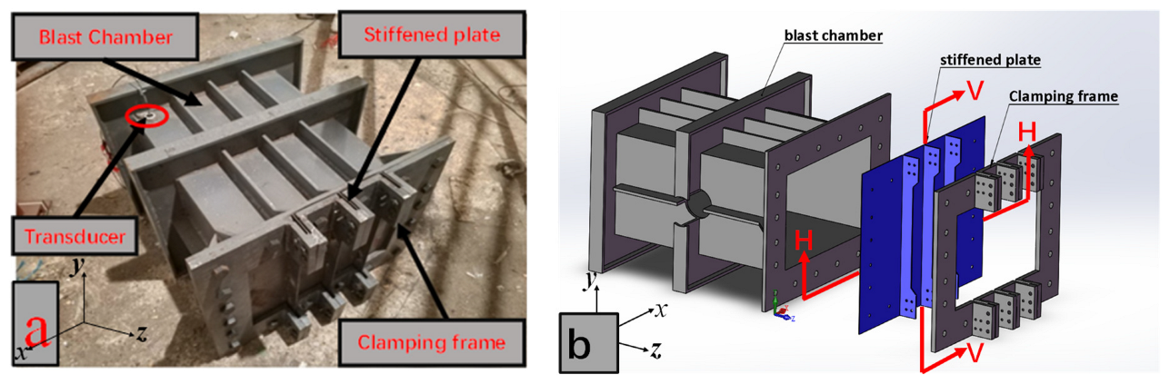
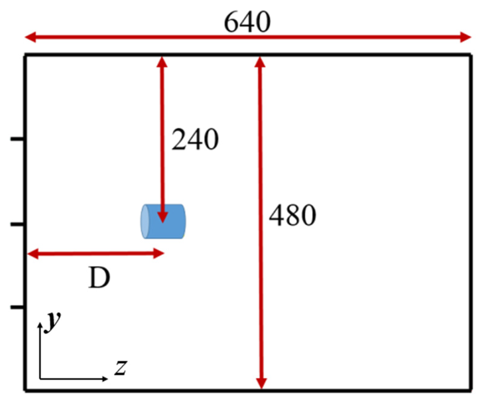
2.1. Confined Cabin Explosion

In the present study, stiffened plates with three ribs were subjected to confined blast loading. In order to perform the confined explosion test, a specific cabin was designed to provide a confined space, as shown in Figure 1. The test cabin was a relatively rigid chamber with one open side. The inner space was about 640 mm × 480 mm × 320 mm in dimension. To ensure that it would not undergo large plastic deformation with multiple tests, the chamber was designed with thick plates and the side walls were also strengthened using stiffeners. The thickness of the side wall and attached stiffener was 10 mm and 12 mm, respectively.
On the uncovered face, the flange was extended outside, for installation of the stiffened plate. The outer dimension of the flange was 700 mm × 540 mm, with the inner cut-off being the open side of the cabin. Therefore, the total size of the stiffened plate was also 700 mm × 540 mm, as shown in Figure 2, which was identical to the outer dimension of the flange. The part inside the dashed frame is the real deformation area and the outside part is the boundary area, where the stiffened plate was clamped and compressed. Three stiffeners, which extended to the outer edge, were welded onto the plate. For the part on the boundary areas, the stiffener height was higher, and screw holes were set on the ribs to facilitate bolt connection, as shown in Figure 3.
The stiffened plate was clamped onto the support frame on the opening side, utilizing bolt connection. It should be noted that both the plate and the stiffeners were clamped in the present study, which is different from the setting in other studies, where only the plate was clamped onto the support structure with the stiffeners welded to the clamped plate. To provide boundary restriction for the plates, and stiffeners as well, a set of clamping fixtures was specially manufactured for this work, which is a called a zigzag fixture. Apart from the screw holes to fit with those on the flange end, screw holes were also set to fit well with those on the ribs of the stiffened plate. This set of fixtures could, not only limit the movement of the stiffened panel, but also impose a restriction on the stiffeners. The fixed stiffened plate in the present article is shown in Figure 4. The test cabin, fixtures, and stiffened plates were all made of Q235 material. The bare charge used in the present study was 110 g or 200 g cylindrical explosive TNT. The explosive was supported by a mounting bracket, which was made of thin paper, and placed in the center of the chamber in height and width directions. The stand-off distance D is the displacement from the cylindrical explosive TNT to the stiffened plate, as shown in Figure 5.

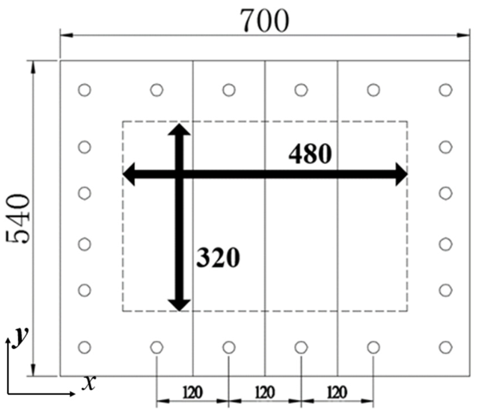
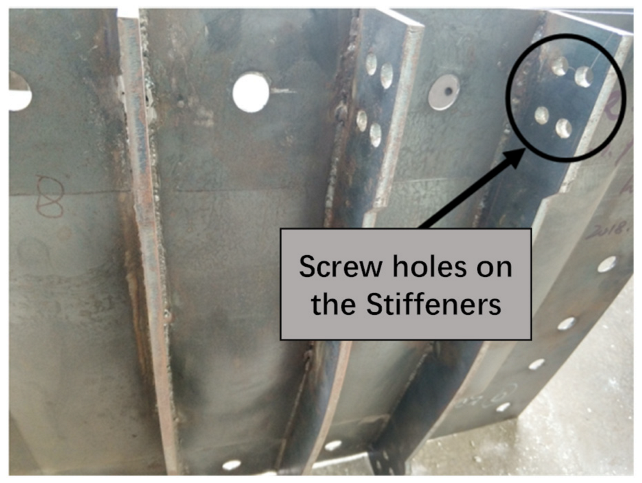
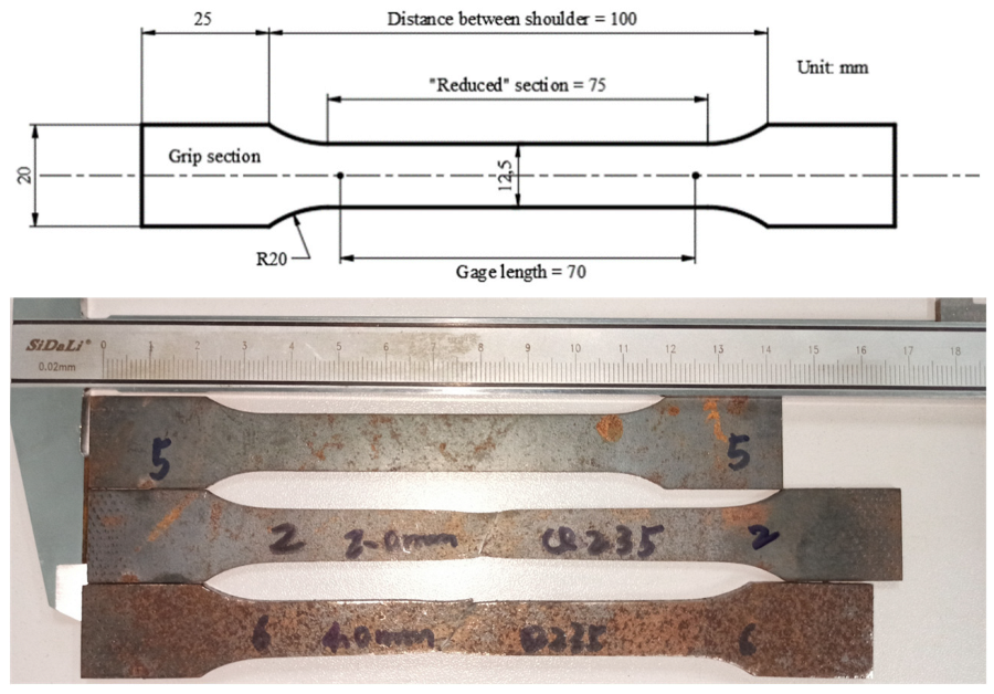
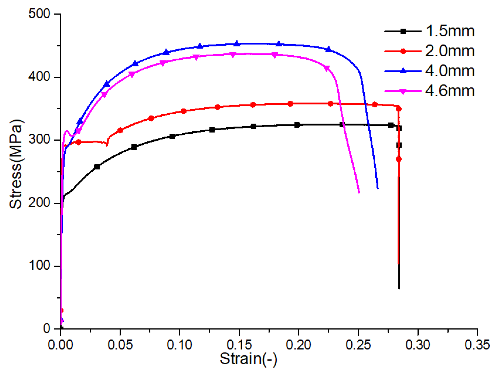
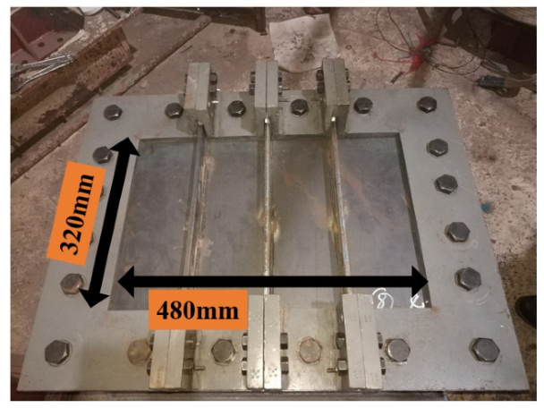
2.2. Stiffened Plate and Material Property

As mentioned above, the overall size of the stiffened plate was 700 × 540 mm, while the area exposed to the explosion after clamping was 480 × 320 mm. Three unidirectional stiffeners were arranged at equal intervals in the width direction, with the spacing being 120 mm. Table 1 lists the dimensions of the stiffened plates and loading condition. Where T, h1, and h2 are the thickness of the plate, the height of the stiffener, and the thickness of the stiffener, respectively.
All the plate and the stiffeners adopted in present study were made of Q235 mild steel. A quasi-static tensile test was conducted to measure the material properties. All the Q235 tensile test specimens were cut from the same plate from which the stiffened plates were fabricated. Five tensile test specimens were tested for each thickness. The dimensions of the tensile test specimens are shown in Figure 6. The quasi-static tensile tests were performed on a tensile test machine, INSTRON 3369, in accordance with standard procedures [31]. The tensile tests were conducted at a rate of 1.0 mm/min, until material failure. The recorded force-displacement data were converted into an engineering stress–strain curve, which is plotted in Figure 7. The mechanical properties of the mild steel for different thickness are summarized in Table 2.

3. Experimental Results

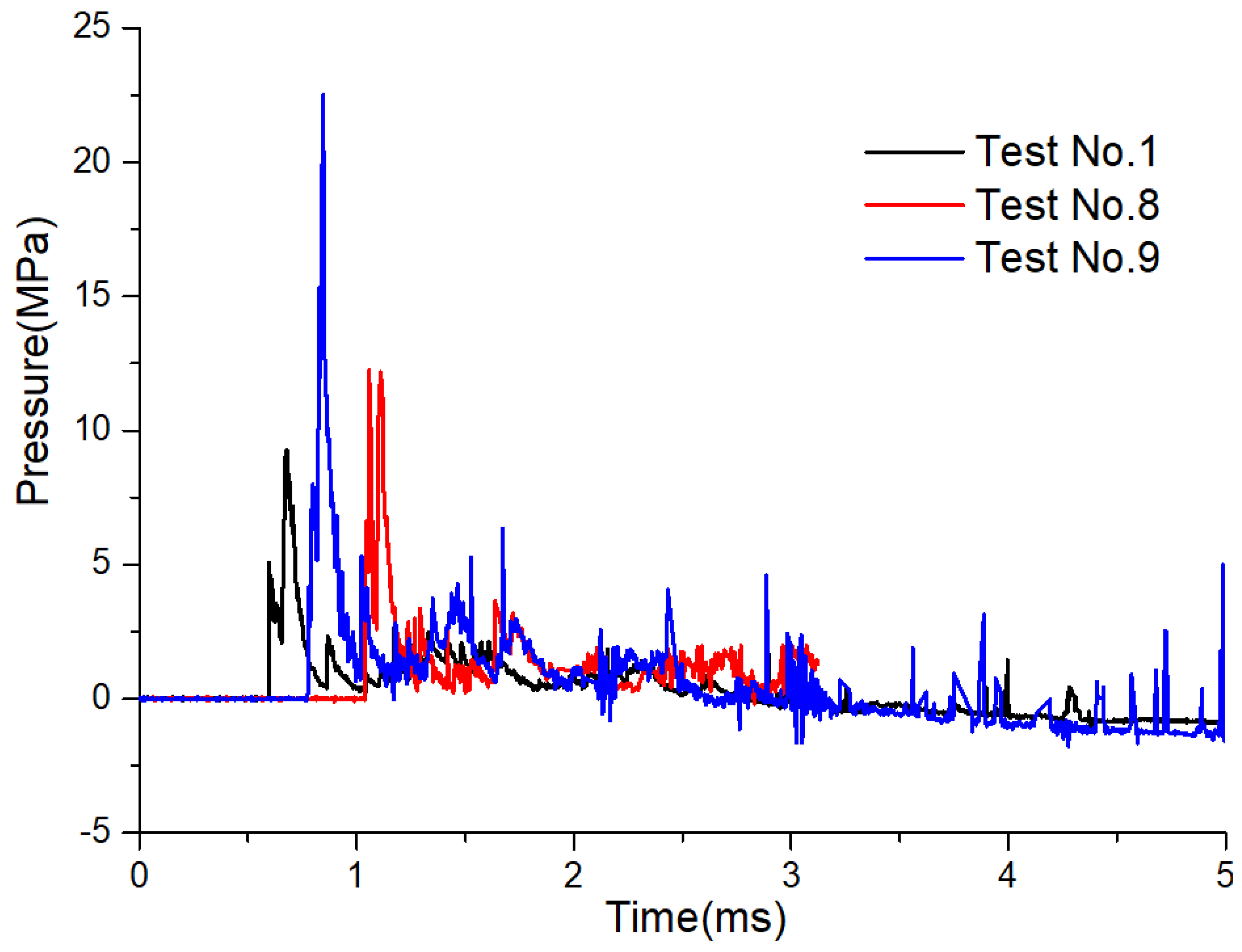
3.1. Shock Wave Pressure

Pressure to time history curves were recorded for all the tests, to measure the loading characteristics under a confined explosion. The transducer was located in the corner of the chamber, posted on the bulkhead opposite to the fixed stiffened plate, as illustrated in Figure 1a. Figure 8 displays the experimental pressure histories recorded by transducer P1 in Tests No. 1,8,9. It is shown that, after the first pressure peak, which was always recorded in the open explosion, several after-peaks were also observed, with long duration. This originates from the multiple reflections and superpositions of the explosion shock waves with reflected waves. In addition, in the present confined space, the static overpressure caused by the explosive products (which is called the quasi-static air pressure) converged to zero with time. Namely, in the case of a confined explosion, the initial shock wave is stronger, but the duration is short. While the quasi-static air pressure shows the opposite characteristics, which is a weak shock with a long duration. Accordingly, the loading characteristic in the confined cabin can be regarded as the joint effect of the initial shock wave and quasi-static air pressure. By comparing overpressure history curves, it was found that the overall loading characteristic was similar, namely a first pressure peak, with several after-peaks. When the stand-off distance or explosive mass was varied, the overpressure magnitude was different.

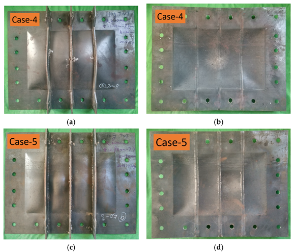
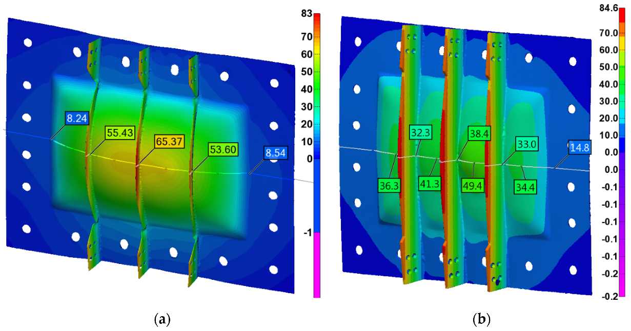
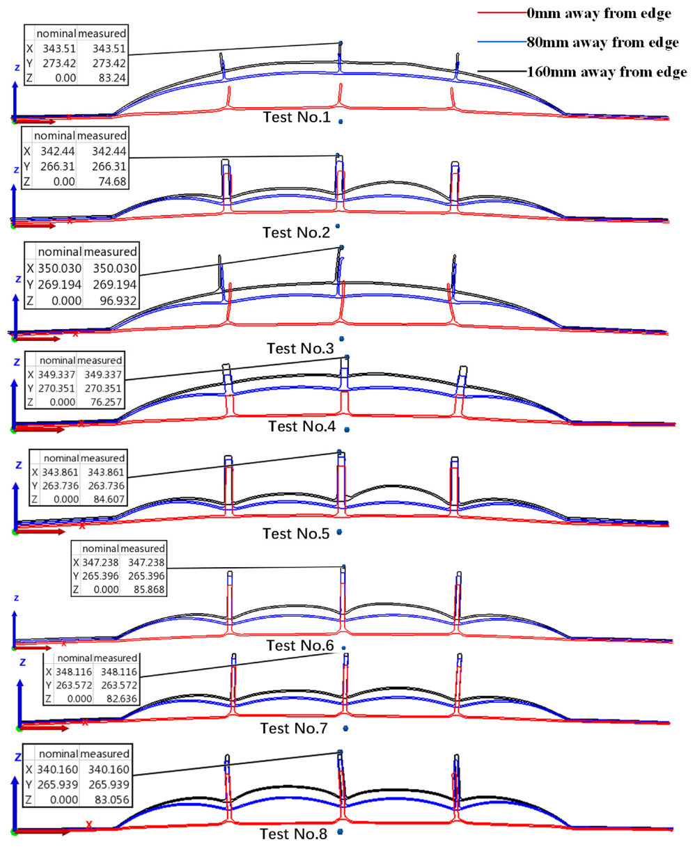
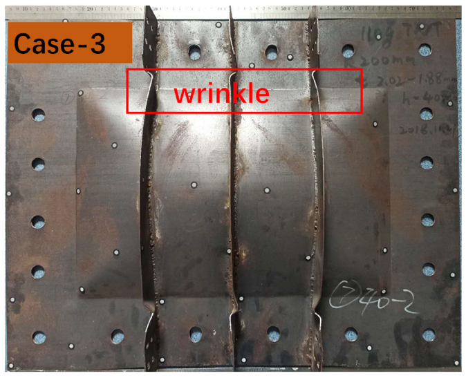
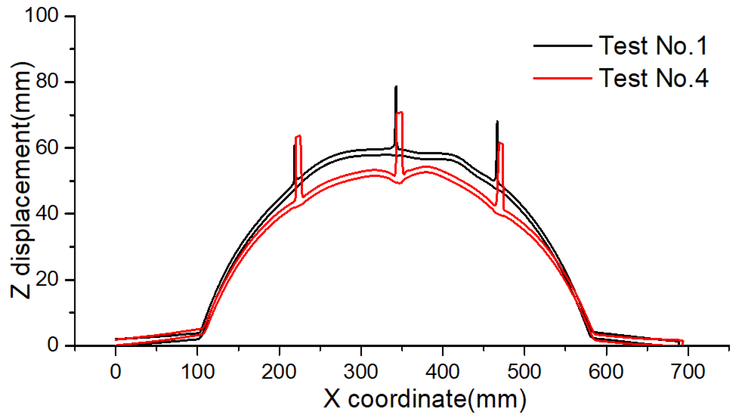
3.2. Failure Modes of Stiffened Plates

The typical failure modes of the stiffened plates after a confined explosion are shown in Figure 9. From the deformation of the stiffened plate under different cases, it was found that the plates within the boundary area showed no obvious vertical deformation under the compression of the flange and the fixture plate. However, along the four inner edges of the flange and the fixture, obvious plastic hinges were formed at the boundary of the flange clamping. The bending and stretching deformations were concentrated in the 480 mm × 320 mm area enclosed by the plastic hinge. In addition, from the corners towards the center of the plate at an angle of 45°, clear yield lines were also observed along the diagonals of the stiffened plate.
As shown in Figure 9, under confined explosion, all the stiffeners and the panels underwent different degrees of deformation. In order to examine the failure pattern of the stiffened plates in detail, the whole post-explosion deformation of stiffened plates was drawn utilizing the 3D scanner technique. All the scanned stiffened plates were stored as STL files, which can be provided upon request. The typical scanned images are shown in Figure 10, which were edited in the PolyWorks MS 2018 program. The color bar signifies the Z displacement of the stiffened plates, where the reference plane is the inner face in contact with the flange. The displacement nephogram confirms that the large deformation focused on the central 480 mm × 320 mm part enclosed by the fixture frame. In Figure 10a, the maximum displacement of the plate is located in the center of the plate, while in Figure 10b, the maximum deformation is located between the center of the two stiffeners.
Two cross-sections are selected to illustrate the deformation characteristics clearly, namely the H-H Section in the horizontal plane and the V-V Section in the vertical plane, as shown in Figure 1b. Three H-H cross-section profiles of all the stiffened plates in the different cases after explosion are illustrated in Figure 11, where the 0 mm, 80 mm, and 160 mm cross-sections are the edge cross-section, the quarter cross-section, and the central cross-section, respectively.
It is clearly found that two typical cross-section profiles are observed, which may correlate with two typical failure modes. The first type of cross-section profile is characterized by a uniform global dome, with the maximum deflection at the center of the plate, which was observed in Test No. 1, 3, and 4. This typical deformation was widely observed in [13,30], which may be termed as Mode I failure (permanent plastic deformation). This plastic deformation is different from other failure modes of structures, which may be called Mode II (tensile failure in the center, tensile failure along the clamp edge, shear failure along the clamp edge, petalling failure in the center, and so on) [6,7,8,9,10]. However, in the present study, this is named as Mode Ia deformation mode, for another permanent plastic deformation mode was also observed. The second type of cross-section profile was characterized by nonuniform dome deformation, with local lattice along the stiffeners, which looks like a “double M” shape when three stiffeners were included in the present study. The maximum deflection was almost at the center of the two stiffeners. This new observation is called the Mode Ib deformation mode, and was observed in Test No. 2, and 5–8. It seems to confirm the numerical prediction in [30], where two stiffeners were set in finite element models.
Figure 12 shows the V-V cross-section deformation profiles at different distances from the edge of the stiffened plates in Test No. 1 and No. 2. The X = 350 section profile is almost the central section, and the X = 410 mm section profile is the central section between the two stiffeners. The black dashed line is the outline of the stiffener. It was found that in Test No. 1, where the stiffened failed in Mode Ia, the two section profiles showed similar deformation mode, with a smoothing curve. While in Test No. 2, where the stiffened plate failed in Mode Ib, the section profile along the stiffeners was identical to that in Test No. 1, and the X = 410 mm section profile appeared a little different, with the curvature in the central part extruded. Another point that needs to be noted, is that the deformation in the X = 410 section profile was larger than that in the central (X = 350) section. This means that in deformation mode Ia, the stiffened plate responses as a whole with the plate and stiffeners behaved similarly, and the maximum displacement was located in the central point of the entire stiffened plate. While in deformation mode Ib, the plate response and the stiffener response were relatively different due to the rigidity difference between them. The deformation of stiff stiffeners is small, which also restricts the displacement of the plate in the corresponding location. Namely the three stiff stiffeners divide the whole plate into four individual parts, with a quadruple specific ratio. The local responses of the individual parts with higher specific ratio is slightly different from the global response in Test No. 1. The response is more local, so the deformation and curvature in the central part is more obvious. The maximum displacement is located in the central point of the individual part, in the middle of the whole plate.
Plate thinning around the boundary edge is the typical characteristic under failure Mode I (plastic deformation), which is displayed in detail in [14,15]. The central H-H cross-section profile of the stiffened plate after explosion in Test No. 1 and Test No. 5 is shown in Figure 13. It should be noted that the Z displacement in Figure 13 was enlarged compared to the X coordinate, hence the plate thinning at typical points (A, B, C, and D noted in Figure 13) is specifically shown in Figure 14. In Figure 14, the dashed line is the section profile, and the solid circle is the imaginary plate thickness. When the point in the section profile is distributed in the circle, this means that the plate thickness in this specific point decreased; namely, plate thinning occurred. Figure 13 and Figure 14 show that when stiffened plate deforms in Mode Ia, plate thinning just appears at the boundary. While thinning of the plate was not only observed at the boundary, but also around the two sides of the stiffeners when the stiffened plate deformed in Mode Ib. A similar phenomenon was also presented in the double stiffened plate in the work of [13], where stiffened plate was subjected to open-air explosion. However, they stressed that thinning occurred only at the side of the stiffener closest to the boundary, which is different from our experimental observation in Test No. 5. It is inferred that the strong restriction on the stiff stiffeners increased the supporting effect of the stiffeners to the plate. Namely, the stiffeners performed as boundary supports for the small plates. Hence, all the “small” plates divided by the stiffeners deformed greatly and thinning around all the “boundaries” was observed.
In present study, the stiffened plates were clamped onto the blast chamber through clamping frames and bolt connections. Although no vertical deformation was observed within the boundary area, there must have been in-plane displacement, as large deformation was generated in the central part, and the upper and lower edges of the stiffened plate shrink inward, which is clearly displayed in Figure 15. This is also shown by the deformation of the perimeter of the bolt holes in the plate, as shown in Figure 15. Figure 16 displays the extended bolt hole for the 2-mm thick stiffened plate, with the stiffener thickness and height being 2 mm and 20 mm, respectively (Test No. 1). It was found that the bolt holes along the left and right sides showed no obvious deformation, while the bolt holes on the upper and lower sides of the stiffened plate experienced large extension. This shows that the bolt clamping on the upper and lower sides was not strong enough to provide fully restriction to the stiffened plate. The boundary area of the stiffened plate slipped a little when subjected to the confined blast loading. Further slipping was partially prevented by the bolt connection when the bolt hole came into a tight contact with the bolts.
By precisely checking the hole extension direction along the upper and lower sides, it was found that the bolt holes extended in the direction from the hole center to the plate center, as shown in Figure 16. This shows that under shockwave loading the main tension in the plate pointed to the center of the stiffened plate. This interesting phenomenon provides another clue for imposing boundary restriction in the numerical model. In the work of R. Villavicencio [32], to study the impact response of rectangular and square stiffened plates under low velocity impact loading, a bolt nut was truncated so they pointed out and an axial displacement existed at the supports, which was thought to be quite important in the dynamic response of the beams or plate in [33,34]. Hence, in their numerical model, the axial restraint at the supports was represented by two conditions, namely the prescribed nodal axial forces at the bolt locations and friction force defined by “automatic surface to surface” contact [35] during the entire simulation. This special setting guaranteed the good agreement between experimental observation and numerical results, in terms of contact force and energy absorption. In terms of the experimental conditions in the present study, a traditional method is to model all the bolts and define a contact algorithm in the numerical simulation. However, from the bolt hole extension direction observed in present study, the prescribed nodal axial forces at the bolt locations, together with the friction force defined by the contact, is also another option to simulate the boundary setting. This method is likely to save time in bolt modeling and avoid mesh distortion around the bolt hole, which will be discussed in detail in the subsequent paper.

4. Discussion

4.1. Effect of Stiffener Restriction

In the present study, the clamping fixture not only limited the movement of the panel, but also imposed a restriction on the stiffeners. Kong [30] presented the failure mode of stiffened panel with only the panel clamped. To illustrate the effect of the boundary condition of the stiffener on the failure modes of stiffeners, the typical failure pattern of Specimen No. 7 in their work is cited here for comparison. The dimension and loading conditions of Specimen No. 7 and Test No. 3 in the present article are given in Table 3.
It was found that the initial condition was almost the same between Test No. 3 and Specimen No. 7 in their work, except for the difference of stiffener restriction condition and stand-off distance. Figure 17 shows the typical uniform global dome deformation of the stiffened plate (Test No. 3 in the present article). It was shown that the global dome deformation seemed to be identical. However, wrinkles were observed at the stiffeners in Test No. 3 by checking the failure of the stiffeners on the boundary edges in detail. This looks like the instability failure of the panel under axil loading, while this special phenomenon was not shown in Specimen No. 7 in [30]. This is explained by that when the stiffeners are clamped, the bolts limit the axil and vertical movement of the stiffeners. Axil force is generated in the deformation process under a confined explosion. When the axil force reaches the critical force of stiffeners, instability is observed in the stiffeners. However, if the stiffeners are stiff enough, instability is hard to produce and wrinkles will not be observed, as was the case in Tests No 5, 6, 7, and 8.
It should be noted that wrinkles were located next to the clamping edge, which is different from static instability, where wrinkles appear at the center of stiffeners. Under a confined explosion, the loading or unloading rate is higher, so the dynamic instability of the stiffeners leads to wrinkles on the edge. The subsequent numerical simulation shows that wrinkles appear in the rebounding process, not the initial expanding process under a confined explosion, which needs to be examined and discussed in detail in the following separate paper on the numerical study.

4.2. Effect of Scaled Distance

X.D. Li et al. [27] presented the effect of stand-off distance on damage to clamped square steel plates under an enclosed explosion. They pointed out four failure modes were observed, which were related to the scaled distance parameter. This means that scaled distance is a vital parameter in dividing failure mode maps. The scaled distance is related to the explosive equivalent and stand-off distance, which is obtained by dimensional analysis and experimental data [18,36]. In Tests No. 6 and 7, the stand-off distance was different from in other conditions, such as the plate thickness and stiffener height being identical, which are listed to illustrate the effect of stand-off distance. From the final failure mode of tests No. 6 and 7, a similar nonuniform dome deformation with local lattice along the stiffeners (Mode Ib) was observed, although the maximum central displacement was different, as shown in Figure 18. This might show that the effect of stand-off distance was negligible in dividing the two type of deformation modes in the present study. The effect of explosive equivalent adopts the experimental results in [30]. Three different TNT charge masses were set in their work, but a uniform global dome with the maximum deflection at the center of the plate (Mode Ia) was observed in all the cases, irrespective of charge mass and venting size. Although the magnitude of global dome deformation is different when the charge mass was varied, the global failure mode could be regarded as identical. From the above analysis, the effect of stand-off distance or charge mass seems to be minor when dividing the different plastic deformation modes, without tearing or shearing failure in the stiffened plate.
In the study of X.D. Li et al. [27], four failure modes were observed when material failures such as tearing and shearing were considered. When the plate material failed in different positions or in different forms, different failure modes appeared in the square plate. Hence, the effect of scaled distance was obvious. However, in the present work, plastic deformation is the research point and the dominant response, and no material failure was included, so the scale distance would affect the magnitude but not the deformation mode. When the charge mass is higher or the stand-off distance is smaller, a new failure mode with material failure is bound to be observed. For example, when the explosive equivalent increased to 200 g, as in the case in Test No. 9, tearing failure around the edge was observed, as shown in Figure 19. However, this is not the research point in present article, as the present study is trying to reveal two typical plastic deformation modes and investigate the possible affecting factors. Obviously, the scaled distance seems to be a weak factor herein, but it greatly affects the magnitude of deformation. It should be noted that this conclusion is based on the premise that the stand-off distance is large enough, as the stand-off distance is equal to the plate dimension in the present study or in [30]. In other words, the stiffened plate was subjected to an almost uniform blast loading. Other possible deformation modes may exist when the explosive is located next to the plate, namely localized blast loading is imposed, which is discussed in detail in [14]. When the stand-off changes from 200 mm to about 10 mm, local deformation, only around the central stiffener or central plate, is likely to be observed, which could include Figure 5b and Figure 6a in [14], where the typical local deformation modes of single stiffened and double stiffened plates under localized blast loading are presented.

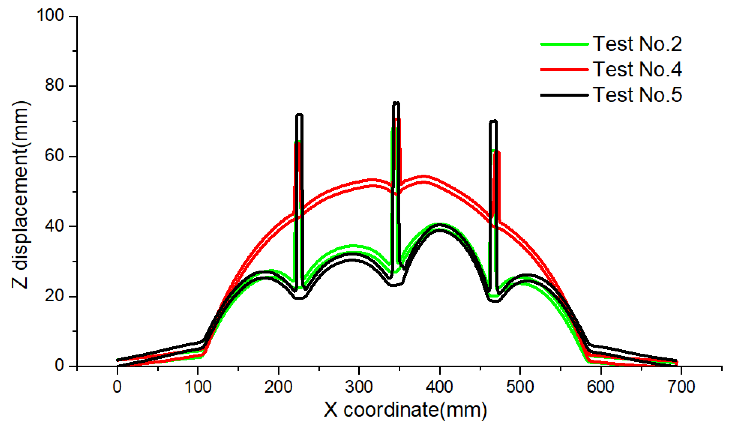
4.3. Effect of Stiffener Thickness

The influence of stiffener thickness on the dynamic response of stiffened plates subjected to confined explosion is examined here. According to the single variable principle, three groups of stiffened plates were selected to illustrate the effect of stiffener thickness, where only the stiffener thickness was different in each group. Figure 20 displays the central H-H cross-section profile of the stiffened plate of Test No. 1 and Test No. 4 after the explosion. It was found that when the stiffener thickness changed from 1.9 mm to 7.7 mm, with the stiffener height being 20 mm, the deformation mode of the stiffened plate was almost the same, namely a uniform global dome deformation of plate and stiffeners together (Mode Ia). The maximum displacement of the stiffened plate in Test No. 4 is slightly less than that of Test No. 1. This shows that with an increase in stiffener thickness, the bending stiffness of whole structure increased and the overall deformation decreased, under a similar confined explosion loading.
Figure 21 displays the central H-H cross-section profile of the stiffened plate of Test No. 2 and Test No. 3 after explosion. It was found that when the stiffener thickness changed from 1.88 mm to 7.8 mm, with the stiffener height being 40 mm, the deformation mode of the stiffened plate changed, from the uniform global dome deformation (Mode Ia) in Test No. 3, to the nonuniform dome deformation with local lattice along the stiffeners (Mode Ib) in Test No. 2. In addition, the maximum displacement of the stiffened plates in Test No. 2 was slightly less than that in Test No. 3. This shows that the stiffener thickness may change the deformation mode of a stiffened plate under certain conditions when subject to a confined explosion. Of course, the maximum displacement results also showed that the increased stiffener thickness enhanced the bending stiffness of the stiffened plate and led to lower deformation under similar loading conditions.
Figure 22 displays the central H-H cross-section profile of the stiffened plate in Tests No. 5 and 6 after explosion. In this group, the plate thickness and stiffener height were 2 mm and 50 mm, respectively, while the stiffener thickness changed from 4 mm to 4.65 mm. It was found that the deformation mode of the stiffened plate was also similar in this group, but the deformation mode was the nonuniform dome deformation with local lattice along the stiffeners (Mode Ib). The maximum displacement of the stiffened plate also decrease when the stiffener thickness increased.
From the analysis above, stiffener thickness affected the rigidity of the stiffened plate and will have an effect on the displacement and deformation mode of a stiffened plate. In the first group, the stiffener height was 20 mm, and an increase of stiffener thickness from 1.9 mm to 7.7 mm did not change the deformation pattern (both deformed in Mode Ia). However, in the second group, when the stiffener height was 40 mm, an increase of stiffener thickness from 1.88 mm to 7.8 mm changed the deformation mode (from Mode Ia to Mode Ib). In the last group, when the stiffener height was 50 mm, the lower thickness was 4 mm. This weaker panel also showed nonuniform dome deformation with local lattice along the stiffeners (Mode Ib); therefore, the increase of stiffener thickness no longer changed the deformation pattern. It is concluded that stiffener thickness may affect the deformation pattern of a stiffened plate under a confined explosion, which is also dependent on the stiffener height. Hence, it is inferred that the transformation of deformation pattern is related to both the stiffener thickness and height.

4.4. Effect of Stiffener Height

As found in Section 4.3, the stiffener height also has an effect on the deformation mode. Two groups of stiffened plates were selected to illustrate the effect of stiffener height, where only stiffener height was varied in each group. Figure 23 displays the central H-H cross-section profile of the stiffened plate in Test No. 1 and Test No. 3 after explosion. It was found that when the stiffener height changed from 20 mm to 40 mm, with the stiffener thickness being about 2 mm, the deformation mode of stiffened plate was almost the same, namely a uniform global dome deformation (Mode Ia). The maximum displacement of the stiffened plate in Test No. 3 was slightly less than that of Test No. 1. This shows that with the stiffener height being increased, the bending stiffness of the whole structure increased, and the overall deformation decreased under a similar confined explosion loading.
Figure 24 displays the central H-H cross-section profile of the stiffened plate of Test No. 2, 4, and 5 after explosion. It was found that when the stiffener height changed from 20 mm to 40 mm and to 50 mm, with the stiffener thickness being about 7.7 mm, the deformation mode of the stiffened plate changed from the uniform global dome deformation (Mode Ia) in Test No. 4, to the nonuniform dome deformation with local lattice along the stiffeners (Mode Ib) in Tests No. 2 and 5. In addition, the maximum displacement of the stiffened plate in Test No. 4 was higher than that of Test No. 2 and slightly higher than that of Test No. 5. This shows that the stiffener height may change the deformation pattern under certain conditions. Of course, the maximum displacement results also show that the increased stiffener height enhanced the bending stiffness of the stiffened plate and led to lower deformation under the same loading conditions.
From the analysis above, stiffener height affected the rigidity of the stiffened plate and had an effect on the deformation degree of the stiffened plate. In the first group, the stiffener thickness was 2 mm, and the increase of stiffener height from 20 mm to 40 mm did not change the deformation pattern. However, in the second group, when the stiffener thickness was 7.7 mm, the increase of stiffener height from 20 mm to 40 mm changed the deformation pattern. It is concluded that stiffener height affects the deformation pattern of a stiffened plate under a confined explosion, which is also dependent on the stiffener thickness. Hence, the consolidates the inference that the transformation of deformation pattern is related to both the stiffener height and thickness.

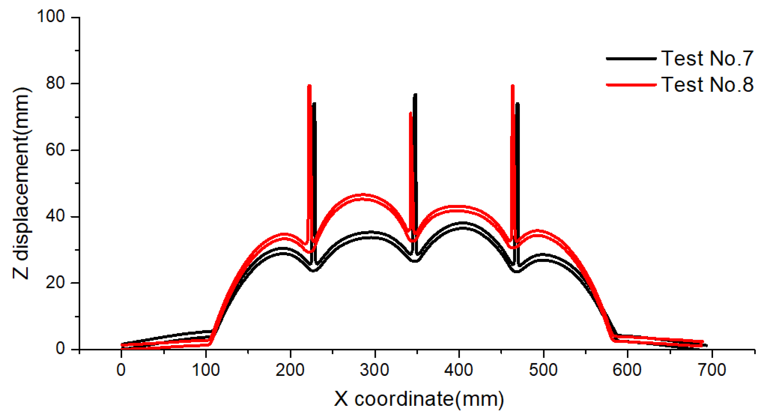
4.5. Effect of Plate Thickness

The present study also examines the influence of plate thickness on the dynamic response of a stiffened plate under confined blast loading. Under a single variable principle, only one group of stiffened plates is selected to illustrate the effect of plate thickness. Figure 25 displays the central H-H cross-section profile of the stiffened plate in Test No. 7 and Test No. 8 after explosion. It was found that when the plate thickness changed from 1.5 mm to 2 mm, with the stiffener height and thickness being 50 mm and 4 mm, respectively, the deformation mode of the stiffened plate was almost the same, namely a nonuniform dome deformation with local lattice along the stiffeners (Mode Ib). The maximum displacement of the stiffened plate in Test No. 8 was higher than that of Test No. 7. This shows that with a plate thickness increase, the bending stiffness of the whole structure increases and the global deformation decreases under similar loading. As the stiffener height and thickness were 50 mm and 4 mm, respectively, in this group, and the stiffeners were stiff enough, the increase of plate thickness from 1.5 mm to 2 mm did not cause a change of deformation mode.

4.6. Relative Strength Factor

From the analysis of affecting factors above, it is concluded that two types of deformation mode are observed when no material failure, such as tearing or shearing, is included. The deformation Mode Ia is the uniform global dome deformation of plate and stiffeners together, and deformation Mode Ib is the nonuniform dome deformation, with local lattice along the stiffeners. In the work in [30], Kong proposed the concept of the mass ratio of stiffener to plate, to represent the appearance of deformation mode Ib in their numerical simulation. However, in the author’s understanding, the relative strength of the stiffener to plate seems to be more important in explaining the division of the two deformation modes. Hence, a relative strength factor K is proposed to clarify the division. The relative strength factor K is defined as:
K = ( M S B / M P ( n + 1 ) )
where B is the stiffened plate width, and n is the stiffener number, Ms and MP are defined as follows:
M S = σ s t h 2 / 4
M P = σ p T 2 / 4
where σ s , t, h, σ p , and T are yield strength of stiffener material, thickness of stiffener, height of stiffener, yield strength of plate material, and plate thickness, respectively. Table 4 lists the related parameters and final deformation mode of the different tests.
The Tests No. 1–8 are the experimental cases in the present study. The Specimens 2–30 are cited from the experimental results of [30] and Simulations SP1–3 are the extended numerical simulation in their work. Table 3 shows that when the relative strength factor is less than 10.9, all the stiffened plates deform in Mode Ia. When the factor increases to 27 and above, the Mode Ib deformation is observed. This trend proves that relative strength factor is a reasonable parameter to define the deformation pattern of stiffened plate subjected to confined explosion. When the relative strength factor is small, the stiffened plate will deform in mode Ia. When this parameter is large, the stiffened plate will deform in mode Ib under a confined explosion. Due to the lack of samples, a specific critical value is not drawn from this experimental observation, which will be discussed in detail in the subsequent paper on numerical and theoretical analysis.

5. Conclusions

In present study, the dynamic response of outer-stiffened plate subjected to confined blast loading was investigated experimentally. A relatively rigid box with one open side was designed, to provide a confined space, and the stiffened plate was fixed onto the opening side using bolt connections. Several field blast experiments of stiffened plates with different arrangements were conducted.
The pressure history under a confined explosion was measured using a transducer posted in the corner of the relatively rigid box. It was found that the pressure time history is much more complicated under a confined explosion. Apart from the initial shock wave, the pressure history always shows many after-peaks with a long duration. The post-explosion deformation of stiffened plates was measured utilizing the 3D scanner technique, and the section profiles were examined in detail. Two typical deformation modes were observed in the stiffened plates; namely, deformation Mode Ia (uniform global dome deformation of plate and stiffeners together), and the deformation Mode Ib (nonuniform dome deformation with local lattice along the stiffeners).
The effect of stiffener restriction, scaled distance, stiffener thickness, stiffener height, and plate thickness on the response of the stiffened plate was discussed. By comparison with the failure mode of a stiffened plate without restriction on the stiffeners, it was found that wrinkles were observed at the edge of stiffeners when the stiffeners were clamped, which seems like dynamic instability of the panel under axil loading. In the present work, plastic deformation was the research objective, so the scaled distance will affect the magnitude but not the deformation mode. When the charge mass is higher or the stand-off distance is small, a new failure mode with material failure is bound to be observed. The present study intended to reveal two typical plastic deformation modes and investigate the possible affecting factors. Hence, the scaled distance seems to be a weak factor herein.
The effect of stiffener height, stiffener thickness, and plate thickness on the dynamic response of a stiffened plate are obvious. Increase of stiffener thickness or height or plate thickness enhances the bending stiffness of stiffened plate and reduces the permanent deflections of the stiffened plate under the same enclosed blast loading. The deformation mode of a stiffened plate under a confined explosion is related to the relative strength of the stiffeners to the plate; hence, a relative strength factor is proposed to clarify the division, which is presented in Equation (1). When the relative strength factor is small (less than 10.9), the stiffened plate deforms in mode Ia. If this parameter is large (27 and above), the stiffened plate deforms in mode Ib. This clear tendency confirms that the relative strength factor is an appropriate criterion to distinguish the two types of deformation mode. As the sample size was small in present article, a specific critical value was not drawn from this experimental observation, and this will be discussed in detail in the subsequent paper on numerical and theoretical analysis.

Author Contributions

Conceptualization, W.X. and H.H.; methodology, W.X., M.L.; software, W.X.; validation, W.X., P.C. and H.H.; formal analysis, W.X., M.L.; investigation, W.X.; resources, H.H.; data curation, P.C.; writing—original draft preparation, W.X.; writing—review and editing, L.M.; visualization, W.X.; supervision, H.H.; project administration, H.H.; funding acquisition, H.H. All authors have read and agreed to the published version of the manuscript.

Funding

This work was supported by the National Natural Science Foundation of China (grant nos. 51679246 and 51979277).

Data Availability Statement

Not applicable.

Acknowledgments

The authors wish to express their gratitude to Qing Yu for his selfless help during the experimental tests and express gratitude to Engineer Junliang Wang for his valuable help in the 3D scanner technique and processing of the post-explosion model.

Conflicts of Interest

The authors declare no conflict of interest.

References

  1. Chung, K.Y.S.; Nurick, G.; Langdon, G.; Iyer, Y. Deformation of thin plates subjected to impulsive load: Part III—an update 25 years on. Int. J. Impact Eng. 2017, 107, 108–117. [Google Scholar] [CrossRef]
  2. McDonald, B.; Bornstein, H.; Langdon, G.; Curry, R.; Daliri, A.; Orifici, A. Experimental response of high strength steels to localised blast loading. Int. J. Impact Eng. 2018, 115, 106–119. [Google Scholar] [CrossRef]
  3. Cloete, T.; Nurick, G.; Palmer, R. The deformation and shear failure of peripherally clamped centrally supported blast loaded circular plates. Int. J. Impact Eng. 2005, 32, 92–117. [Google Scholar] [CrossRef]
  4. Patrice, L.; Anne-Gaëlle, G.; Bruno, L.; Lebléc, B.; Dragond, A. Ship structure steel plate failure under near-feld air-blast loading: Numerical simulations vs experiment. Int. J. Impact Eng. 2013, 62, 88–98. [Google Scholar]
  5. Wierzbicki, T. Petalling of plates under explosive and impact loading. Int. J. Impact Eng. 1999, 22, 935–954. [Google Scholar] [CrossRef]
  6. Zhao, X.; Tiwari, V.; Sutton, M.A.; Deng, X.; Fourney, W.L.; Leiste, U. Scaling of the deformation histories for clamped circular plates subjected to blast loading by buried charges. Int. J. Impact Eng. 2013, 54, 31–50. [Google Scholar] [CrossRef]
  7. Yao, S.; Zhang, D.; Lu, F. Dimensionless numbers for dynamic response analysis of clamped square plates subjected to blast loading. Arch. Appl. Mech. 2015, 85, 735–744. [Google Scholar] [CrossRef]
  8. Jacob, N.; Nurick, G.; Langdon, G. The effect of stand-off distance on the failure of fully clamped circular mild steel plates subjected to blast loads. Eng. Struct. 2007, 29, 2723–2736. [Google Scholar] [CrossRef]
  9. Teeling-Smith, R.; Nurick, G. The deformation and tearing of thin circular plates subjected to impulsive loads. Int. J. Impact Eng. 1991, 11, 77–91. [Google Scholar] [CrossRef]
  10. Nurick, G.; Shave, G. The deformation and tearing of thin square plates subjected to impulsive loads—An experimental study. Int. J. Impact Eng. 1996, 18, 99–116. [Google Scholar] [CrossRef]
  11. Nurick, G.; Olson, M.; Fagnan, J.; Levin, A. Deformation and tearing of blast-loaded stiffened square plates. Int. J. Impact Eng. 1995, 16, 273–291. [Google Scholar] [CrossRef]
  12. Gupta, N.K.; Kumar, P.; Hegde, S. On deformation and tearing of stiffened and unstiffened square plates subjected to under-water explosion—A numerical study. Int. J. Mech. Sci. 2010, 52, 733–744. [Google Scholar] [CrossRef]
  13. Yuen, S.C.K.; Nurick, G. Experimental and numerical studies on the response of quadrangular stiffened plates. Part I: Subjected to uniform blast load. Int. J. Impact Eng. 2005, 31, 55–83. [Google Scholar] [CrossRef]
  14. Langdon, G.; Yuen, S.K.; Nurick, G. Experimental and numerical studies on the response of quadrangular stiffened plates. Part II: Localised blast loading. Int. J. Impact Eng. 2005, 31, 85–111. [Google Scholar] [CrossRef]
  15. Bonorchis, D.; Nurick, G. The analysis and simulation of welded stiffener plates subjected to localised blast loading. Int. J. Impact Eng. 2010, 37, 260–273. [Google Scholar] [CrossRef]
  16. Edri, I.; Savir, Z.; Feldgun, V.; Karinski, Y.; Yankelevsky, D. On Blast Pressure Analysis Due to a Partially Confined Explosion: I. Experimental Studies. Int. J. Prot. Struct. 2011, 2, 1–20. [Google Scholar] [CrossRef]
  17. Krauthammer, T. Modern Protective Structures; CRC Press: Boca Raton, FL, USA, 2008. [Google Scholar] [CrossRef]
  18. Baker, W.E.; Cox, P.A.; Westine, P.S.; Kulesz, J.J.; Strehlow, R.A. Explosion Hazards and Evaluation; Elsevier: Amsterdam, The Netherlands, 1983. [Google Scholar]
  19. Bangash, M.Y.H.; Bangash, T. Explosion-Resistant Buildings; Springer: Berlin/Heidelberg, Germany, 2006. [Google Scholar]
  20. Salvado, F.C.; Tavares, A.J.; Teixeira-DiasbJoão, F.; Cardosoad, B. Confined explosions: The effect of compartment geometry. J. Loss Prev. Process Ind. 2017, 48, 126–144. [Google Scholar] [CrossRef] [Green Version]
  21. Hou, H.L.; Zhu, X.; Li, W.; Mei, Z.-Y. Experimental studies on characteristics of blast loading when exploded inside ship cabin. J. Ship Mech. 2010, 14, 901–907. (In Chinese) [Google Scholar]
  22. Geretto, C.; Yuen, S.C.K.; Nurick, G. An experimental study of the effects of degrees of confinement on the response of square mild steel plates subjected to blast loading. Int. J. Impact Eng. 2015, 79, 32–44. [Google Scholar] [CrossRef]
  23. Yao, S.; Zhang, D.; Lu, F. Dimensionless number for dynamic response analysis of box-shaped structures under internal blast loading. Int. J. Impact Eng. 2016, 98, 13–18. [Google Scholar] [CrossRef]
  24. Yao, S.; Zhang, D.; Lu, F.; Chen, X.; Zhao, P. A combined experimental and numerical investigation on the scaling laws for steel box structures subjected to internal blast loading. Int. J. Impact Eng. 2017, 102, 36–46. [Google Scholar] [CrossRef]
  25. Yao, S.; Zhang, D.; Lu, F.; Li, X. Experimental and numerical studies on the failure modes of steel cabin structure subjected to internal blast loading. Int. J. Impact Eng. 2017, 110, 279–287. [Google Scholar] [CrossRef]
  26. Yao, S.; Zhang, D.; Lu, Z.; Lin, Y.; Lu, F. Experimental and numerical investigation on the dynamic response of steel chamber under internal blast. Eng. Struct. 2018, 168, 877–888. [Google Scholar] [CrossRef]
  27. Li, X.; Yin, J.; Zhao, P.; Zhang, L.; Xu, Y.; Wang, Q.; Zhang, P. The effect of stand-off distance on damage to clamped square steel plates under enclosed explosion. Structures 2020, 25, 965–978. [Google Scholar] [CrossRef]
  28. Li, Y.; Zhang, L.; Xiao, D.; Zhao, T.; Du, Z.; Wu, W.; Fang, D. Experiment and numerical study on dynamic response of liquid cabin under internal blast loading. Thin-Walled Struct. 2019, 145, 106405. [Google Scholar] [CrossRef]
  29. Zhao, N.; Yao, S.; Zhang, D.; Lu, F.; Sun, C. Experimental and numerical studies on the dynamic response of stiffened plates under confined blast loads. Thin-Walled Struct. 2020, 154, 106839. [Google Scholar] [CrossRef]
  30. Zheng, C.; Kong, X.-S.; Wu, W.-G.; Xu, S.-X.; Guan, Z.-W. Experimental and numerical studies on the dynamic response of steel plates subjected to confined blast loading. Int. J. Impact Eng. 2018, 113, 144–160. [Google Scholar] [CrossRef]
  31. ASTM E8-04; Standard methods of tension testing of metallic materials. ASTM (American Society for Testing and Materials): West Conshohocken, PA, USA, 2009.
  32. Villavicencio, R.; Soares, C.G. Impact response of rectangular and square stiffened plates supported on two opposite edges. Thin-Walled Struct. 2013, 68, 164–182. [Google Scholar] [CrossRef]
  33. Jones, N. Influence of in-plane displacements at the boundaries of rigid-plastic beams and plates. Int. J. Mech. Sci. 1973, 15, 547–561. [Google Scholar] [CrossRef]
  34. Villavicencio, R.; Soares, C.G. Numerical modelling of the boundary conditions on beams stuck transversely by a mass. Int. J. Impact Eng. 2011, 38, 384–396. [Google Scholar] [CrossRef]
  35. Hallquist, J.O. LS-DYNA Theory Manual; Livermore Software Technology Corporation: Livermore, CA, USA, 2010. [Google Scholar]
  36. Josef, H. The Dynamics of Explosion and Its Use; Elsevier Scientifc Publishing Company: New York, NY, USA, 1979. [Google Scholar]
Figure 1. Experimental set up for confined explosion: (a) experimental arrangement, (b) schematic of experimental arrangement.
Metals 12 00859 g001
Figure 2. Schematic of stiffened plates.
Metals 12 00859 g002
Figure 3. Screw hole on the stiffeners.
Metals 12 00859 g003
Figure 4. Fixed stiffened plate, with bolt connection.
Metals 12 00859 g004
Figure 5. Explosive setting.
Metals 12 00859 g005
Figure 6. Dimension of the tensile test specimen.
Metals 12 00859 g006
Figure 7. Engineering stress–strain curve of mild steel Q235.
Metals 12 00859 g007
Figure 8. Pressure history under different cases.
Metals 12 00859 g008
Figure 9. Typical failure modes of the stiffened plates: (a) front and (b) back view of Test No. 4; (c) front and (d) back view of Test No. 5.
Metals 12 00859 g009
Figure 10. Displacement nephogram using the 3D scanner technique: (a) Test No. 1, (b) Test No. 5.
Metals 12 00859 g010
Figure 11. H-H cross-section profile in different cases.
Metals 12 00859 g011
Figure 12. V-V cross-section profile of Tests No. 1 and 2.
Metals 12 00859 g012
Figure 13. Plate thinning in Tests No. 1 and 5.
Metals 12 00859 g013
Figure 14. Plate thinning at typical points.
Metals 12 00859 g014
Figure 15. Edge shrink and bolt extension.
Metals 12 00859 g015
Figure 16. Bolt extension and direction in Test No. 1.
Metals 12 00859 g016
Figure 17. Failure mode of stiffened plate: Test No. 3.
Metals 12 00859 g017
Figure 18. Central H-H section profile of Tests No. 6 and 7.
Metals 12 00859 g018
Figure 19. Tearing failure along the edges in Test No. 9.
Metals 12 00859 g019
Figure 20. Central H-H section profile of Tests No. 1 and 4.
Metals 12 00859 g020
Figure 21. Central H-H section profile of Tests No. 2 and 3.
Metals 12 00859 g021
Figure 22. Central H-H section profile of Tests No. 5 and 6.
Metals 12 00859 g022
Figure 23. Central H-H section profile of Tests No. 1 and 3.
Metals 12 00859 g023
Figure 24. Central H-H section profile of Tests No. 2, 4, and 5.
Metals 12 00859 g024
Figure 25. Central H-H section profile of Tests No. 7 and 8.
Metals 12 00859 g025
Table 1. Dimensions of the stiffened plates and loading condition.
Test No. Plate Thickness
T/mm
Stiffener
Height
h1/mm
Stiffener
Thickness
h2/mm
Stand-Off Distance
D/mm
TNT Mass
m/g
11.92201.90200110
22.02407.80200110
32.02401.88200110
41.88207.70200110
51.98507.70200110
62.00504.65200110
72.00504.00320110
81.50504.00320110
93.40202.00320200
Table 2. Mechanical properties of Q235.
PropertyUnits1.5 mm2 mm4.0 mm4.65 mm
DensityKg/m37800780078007800
Young’s modulusGPa205205205205
Poisson’s ratio-0.320.320.320.32
Yield stressMPa210280280305
Ultimate tensile stressMPa325358453437
Fracture strain-0.280.280.260.25
Table 3. Dimensions and loading condition of typical specimens.
Plate CasePlate Thickness
T/mm
Stiffener Height
h1/mm
Stiffener Thickness
h2/mm
Stand-Off Distance
D/mm
TNT Mass
M/g
Test No. 32.02 401.88 200110
Specimen No. 72.30402.30400110
Table 4. Relative factors and final deformation mode.
BnThtKMode
Specimen 2680024.8303.70.54Ia
Specimen 980023.7302.70.67Ia
Specimen 2880024.8304.80.70Ia
Specimen 3080034.8303.70.72Ia
Specimen 280021.8201.80.83Ia
Specimen 1180033.7302.70.89Ia
Specimen 2780024.8403.70.96Ia
Specimen 380021.8202.31.06Ia
Specimen 2380022.7302.31.06Ia
Specimen 1080023.7402.71.18Ia
Specimen 2980024.8404.81.25Ia
Specimen 480021.8251.81.30Ia
Specimen 1480022.3302.31.47Ia
Specimen 1980022.3302.31.47Ia
Simulation SP180023.52581.53Ia
Specimen 1280033.7402.71.58Ia
Specimen 580021.8252.31.66Ia
Specimen 2480022.7402.31.89Ia
Specimen 1680032.3302.31.96Ia
Specimen 2180032.3302.31.96Ia
Test 132031.92201.92.58Ia
Specimen 1580022.3402.32.61Ia
Specimen 2080022.3402.32.61Ia
Specimen 780032.3402.33.48Ia
Specimen 1780032.3402.33.48Ia
Simulation SP2800235088.33Ia
Test 332032.02401.889.21Ia
Test 432031.88207.710.89Ia
Simulation SP380022.575827.00Ib
Test 73203250431.25Ib
Test 632032504.6536.33Ib
Test 232032.02407.838.23Ib
Test 832031.550455.56Ib
Test 532031.98507.761.38Ib
Publisher’s Note: MDPI stays neutral with regard to jurisdictional claims in published maps and institutional affiliations.

