Abstract
This paper presents the results of a comprehensive study of the erosive wear resistance, strength, and adhesive characteristics of the high-temperature structural titanium alloy Ti-5.7Al-3.8Mo-1.2Zr-1.3Sn (the Russian grade VT8M-1) with coarse-grained and ultrafine-grained (UFG) structures and a protective erosion-resistant TiVN coating produced by physical vapor deposition (PVD), deposited on the alloy surface. A microscopic analysis of the areas subjected to the action of abrasive particles was performed, and different characters of erosive wear were revealed depending on the structural state of the alloy. The obtained results convincingly demonstrate that by means of refining the grain structure of alloys and depositing a protective ion-plasma TiVN coating on the alloy surface, it is possible to significantly increase the erosion resistance of materials operating under high loads and in aggressive environments.
1. Introduction
Research performed in the past decade shows that the ultrafine-grained (UFG) structure formation in Ti alloys enables a considerable enhancement of specific strength and fatigue resistance, which makes it possible to increase the performance properties of products made thereof [1,2,3,4]. At the same time, there are problems in using UFG Ti alloys in aggressive environments involving corrosion and erosion, e.g., in aircraft-engine building [5]. The problem of erosive wear of critical parts made of titanium alloys is especially acute, since such wear causes a change in the geometry and, as a result, entails a quick decrease in efficiency and rapid failure.
The process of the erosive wear of titanium parts during their operation in gas-turbine engines (GTEs) is a complex phenomenon due to the diversity of the shapes of solid particles, their velocities and angles of attack, the trajectories of their motion, and interaction with the surface. In order to increase the erosive wear resistance and the performance reliability in such environments, metallic materials are traditionally subjected to surface treatment by protective coating deposition [6,7].
In this regard, the use of erosion-resistant physical vapor deposition (PVD) coatings on UFG metals and alloys is a highly promising method. Recent studies showed that PVD coatings applied onto a substrate of the UFG Ti-6Al-4V titanium alloy have sufficiently high adhesion strength, significantly higher than the strength of the same coating applied onto the Ti-6Al-4V coarse-grained alloy (CG) [8,9].
In this work, the authors used, as the material for the investigation, the commercial Ti-5.7Al-3.8Mo-1.2Zr-1.3Sn titanium alloy (the Russian grade VT8M-1), which is widely applied as a structural material in engine building and power engineering for the production of critical parts [10]. Its distinctive feature that distinguishes it from the well-known titanium alloy Ti-6Al-4V is a higher hot strength that enables producing parts that can operate at higher temperatures (up to 550 °C).
As the protective coating for the investigation, the authors selected the TiVN PVD coating which, as recently found [9,11], efficiently increases the wear resistance of titanium parts operating in extreme environments and is promising for the use as a protection from an intensive abrasion. Compared to the titanium nitride (TiN) coatings that are extensively studied and described in scientific literature, the TiVN coating combines the service properties of TiN coatings and, additionally, exhibits increased resistance to erosive wear [9,11]. In the present work, as a continuation of earlier studies, the authors also consider whether TiVN coating retains its wear resistance on titanium substrates with different structures. It is expected that the formation of a UFG structure in VT8M-1 will increase both the strength of the material itself and the adhesion strength of the PVD coating applied onto it.
In this paper, the authors studied the effect of grain refinement in the titanium alloy VT8M-1 with UFG and CG structures on the adhesion and contact strength of TiVN PVD coating. The coated samples of the alloy were thoroughly tested for erosive wear resistance and its mechanisms were also analyzed. The results of this study represent a significant interest for use in engine building and power engineering, where parts operate under extreme conditions.
2. Materials and Methods
2.1. Substrate Material
Rods of the VT8M-1 titanium alloy with a diameter of 70 mm in the hot-rolled condition of the following chemical composition (in wt.%): Ti-5.7Al-3.8 Mo-1.2Zr-1.3Sn, were manufactured by the VSMPO AVISMA Corporation (Verkhnyaya Salda, Russia). To provide the conditions of plastic deformation, the alloy was subjected to a preliminary heat treatment via water quenching from a temperature of 940 °C and subsequent annealing at 700 °C with air cooling. The UFG state in the VT8M-1 alloy was produced by the commercial method of rotary swaging (RS) from a diameter of 70 mm to 30 mm (e = 1.7, the strain rate was higher than 300 mm s−1). The RS procedure is described in more detail elsewhere [12]. Thin foils for TEM were prepared to study the fine structure of the alloy after rotary swaging: the samples were thinned to 0.1 mm on abrasive wheels, removed from the workpiece, and thinning was performed by jet electropolishing at a temperature of −30 °C and a voltage of 25V using a TenuPol-5 device in electrolyte with the composition 60 mL HCl4, 600 mL methanol (CH3OH), and 360 mL butanol (C4H9OH). The resulting foils were studied in a JEM-2100 TEM (JEOL Ltd., Tokyo, Japan) with an accelerating voltage of 200 kV.
2.2. Surface Modification
In the deposition of PVD coatings on metallic materials, an important role is played by the surface quality, the absence of surface defects, and low surface roughness. Prior to the coating deposition, the surfaces of the samples with the initial coarse-grained (CG) and UFG structures were subjected to mechanical grinding with the P600-P800 abrasive, followed by electrolytic plasma polishing (EPP, LLC NPP UAST, Ufa, Russia), which is applied for the polishing of complex-profile parts made of Ti alloys and other structural materials [13,14]. In this study, the EPP treatment of the samples was conducted via the previously developed regime [13] in an electrolyte of low-concentrated 5% NH4F aqueous solution (LLC SigmaTek, Khimki, Russia) at an electrical current voltage of 300–350 V between the part and the electrolyte. The samples were polished at current densities from 0.2 to 0.5 A/dm2, at a temperature of 80 ± 10 °C, for 5 min. After the treatment, the surface roughness of the samples reached Ra = 0.02–0.04 μm and acquired a mirror-like metallic finish. Surface roughness was measured on a Mitutoyo Surftest SJ-210 (Mitutoyo Corporation, Kawasaki, Japan) profilometer. Five measurements of the Ra parameter were carried out and the average value was determined. The samples were finally cleaned using an ultrasonic unit in deionized water, and then degreased with alcohol and acetone mixture before coating.
A multilayer TiVN coating was deposited onto the samples with a previously prepared surface. The deposition of the coating onto the sample surface was performed in a single cycle in a special vacuum-plasma plant VU-2M (JSC Smorgon Optical Machine Tool Plant, Smorgon, Belarus) by the Arc-PVD method in the regime of ion-assisted deposition with a PINK-type ion source in nitrogen medium, using two cathodes—Ti and V. The residual gas pressure was (1 … 2) ×10–2 Pa, the bias voltage varied from 600 to 1500 V, the deposition temperature was 400 ± 50 °C. The processing time was determined by the deposition rate of 8 μm/h. The coating architecture was formed by alternating the deposition times of each layer. A sublayer of pure V was deposited onto the substrate surface for 8 min, the first functional layer of TiVN—for 30 min, an intermediate sublayer of TiV—for 8 min, and the final layer of TiVN—for 30 min. The deposition process is described in detail in the authors’ recent papers [8,9,11].
2.3. Coating Evaluation Procedures
For coating certification (microhardness, adhesion strength measurements), the round samples were prepared separately—“witness” samples with a diameter of 20 mm and a thickness of 3 mm. The characterization of the coating deposited on substrates with different microstructures included microhardness testing under a load of 50 g for 15 s on a Struers Duramin facility (Struers A/S, Ballerup, Denmark). At least 10 measurements were taken in each sample. The mean and standard deviations were calculated. The coating thickness was measured with the help of a Nikon-100M light optical microscope (Nikon Corporation, Tokyo, Japan) with a magnitude from 100× to 500× in spherical specimens produced with a CSM Calotest facility (CSM Instruments, Switzerland). The principle of this facility lies in the abrasion of the sample surface with a steel ball rotating at a constant rate, until a micro-section with the shape of a spherical crater is produced. The spherical sections were prepared with the application of the Calotest Hi-quality (0.5–1 and 0–0.2 μm) water base diamond suspensions.
Precision measurements of the adhesive strength of the coating to the substrate were made by a scratch test on a CSM Instruments Scratch Tester (CSM Instruments, Switzerland) in accordance with the standard procedure (ASTM C1624 Standard Test Method for Adhesion Strength and Mechanical Failure Modes of Ceramic Coatings by Quantitative Single Point Scratch Testing). The testing was performed with a diamond indenter of the Rockwell type with a tip radius of 0.02 mm and an angle of 120°. The indenter was used to scratch the surface with a load gradually increasing from 0.03 N to 20 N.
During the tests, the critical load Lc was determined when there was a complete failure of attaching the coating to the substrate. The failure was recorded from the jump-like penetration of the indenter into the base material, which, in most cases, resulted in the brittle cleavage of the coating. The onset of the failure was determined from the acoustic emission signal. The procedure is described in more detail in [9].
From the experimental data, the equivalent contact stresses, which have a meaning of contact strength, were calculated using the Tresca-Saint Venant criterion [15], which enables indirectly evaluating the strength of adhesion of a coating to the substrate in the area of contact between the indenter and the sample:
where σ1 and σ3 are the maximum and minimum principal stresses; (MPa) is the maximum pressure in a contact between the indenter and the sample; L (N) is the load acting on the indenter; R (mm) is the indenter radius; h (mm) is the indentation depth; and ν is the Poisson ratio.
The internal residual stresses in the coating on substrates with a CG and UFG structure were evaluated using a Rigaku X-ray diffractometer (Rigaku Corporation, Tokyo, Japan) according to the sin2ψ procedure described elsewhere [16,17].
With a view to evaluate the fracture character of the coating and the alloy surface after the erosion tests, the wear region (the area of maximum wear) was studied using a JEOL JSM-6390 (JEOL Ltd., Tokyo, Japan) scanning electron microscope. In addition, a cross section was prepared that was used to study the wear profile relief.
2.4. Erosion Testing
For erosive wear tests, the samples of 20 mm × 15 mm × 4 mm (length × width × thickness) were cut from the rods using electric spark cutting. The erosive wear tests of the samples were performed on a special test bench using the method of comparative tests and mass variation in accordance with the ASTM G76-18 “Standard Test Method for Conducting Erosion Tests by Solid Particle Impingement Using Gas Jets”. This standard covers metallic materials and coatings and establishes a method for their testing for erosive wear in a solid particle flow. The description of the test bench is given in [11]. The principle of the erosive wear of the samples is shown in Figure 1.
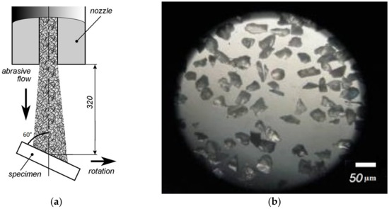
Figure 1.
Principle of the erosive wear of the samples (a) and an optical image of the abrasive Al2O3 particles (b).
In accordance with the ASTM G76-18 standard, the F-280 Al2O3 abrasive particles (Figure 1b) were used as the erodent material. It is a white crystalline powder consisting of corundum crystals with bulk grain sizes from 0.040 up to 0.053 mm.
The erosion test used multiple “wear-and-weigh” cycles. During the test, samples were moved in a circle at a speed of 800 rpm and passed under the jet of abrasive particles emitted from a nozzle with a diameter of 8 mm (Figure 1a). The samples were rigidly fixed at an angle of 60° to the direction of movement. This angle of attack was chosen because of the maximum sample weight loss recorded at this angle in previous tests. The flow rate of the abrasive particles was set at 1.5 g/s, and the speed of the abrasive particles was 30 m/s. Before weighing, one test cycle lasted 60 s, and the whole test consisted of 10 cycles. Estimation of erosion resistance was performed by reducing the weight of the samples, which were measured before the experiment and during the test. The weight of the samples was measured on Mettler Toledo XP205 analytical scales (Mettler Toledo, Switzerland) through equal periods of time. Three samples were tested and weighed under the same conditions, and the average erosion rate was calculated.
3. Results
3.1. Substrate Structure
The globular-lamellar structure produced during the heat treatment represented the α-phase plates divided by the β-phase interlayers, and the primary α-phase of globular morphology (Figure 2a). The fraction of the primary globular α-phase was about 25%, the average globule size was 5 μm, and the average thickness of the α-phase plates was 0.12 μm. During the RS processing, the lamellar part of the structure transformed almost completely into a globular one (Figure 2b), and a UFG structure was formed with an average size of the α- and β-phases ~0.3 μm (Figure 2c), having a higher deformed elongated primary α-phase [12].
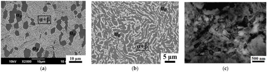
Figure 2.
Structure of the Ti alloy in different states: (a) CG after HT; (b) UFG, SEM; (c) UFG, TEM.
3.2. Coating Architecture and Properties
In the process of physical vapor deposition, a TiVN coating with a total thickness of about 5.7 μm was formed on the substrates of the CG and UFG Ti alloy (Figure 3). The measurements of the roughness (Ra) of the TiVN coating on substrates with the initial coarse-grained and ultrafine-grained structures were 0.268 μm and 0.264 μm, respectively. In view of their very close values, the authors did not take into account the effect of the coating roughness on wear resistance In the SEM image of the cross section of the coated sample, two coating layers are clearly visible. These are the functional TiVN layers with a thickness of 2.5 μm and thinner intermediate sublayers with a thickness of about 0.2–0.3 μm at the “substrate-coating” interface and between the functional layers. The intermediate sublayers play an essential role in the formation of stronger adhesive bonds between the coating material and the substrate material, reduce the internal stresses and interrupt the columnar growth of ion-plasma coatings [8,9,11]. The microhardness of the coating on the substrates sharply increases, especially strongly it is observed on the UFG alloy [9].
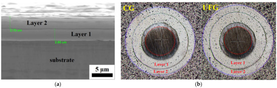
Figure 3.
Coating architecture: (a) SEM image, (b) OM picture of the spherical section.
3.3. Adhesive and Contact Strength of the Coating on CG and UFG Substrates
The strength of the adhesion of the coating to the substrate is the most important characteristic of ion-plasma coatings and has a considerable effect on most service properties, including erosive wear resistance [7,11,18]. The adhesive strength of the TiVN coating on the UFG Ti-6Al-4V titanium alloy substrates was recently investigated in detail in our work [9].
The scratch tests of the samples with a TiVN coating demonstrate that the values of the critical load at which the first cracks emerge in the coating (Lc1) are similar for the CG and UFG Ti alloys, and the value of the load at which the first cleavages emerge (Lc2) is much higher for the UFG Ti alloy than that for the CG Ti alloy (Table 1). The cleavages in the coating on the UFG samples emerge at a rather high critical load of Lc2 = 18.1 N, which indicates a high adhesive strength of the coating to the substrate with an ultrafine-grained structure.

Table 1.
Scratch test results.
In addition, in this work, based on the scratch-test experimental data, the mechanical stresses and contact strength of the coatings were calculated in accordance with the well-known Tresca-Saint Venant yield condition [19]. The calculated values of contact strength have a sense of the compressive strength of a material and enable deriving the conventional “stress-penetration” mechanical curves for the evaluation of the erosive action of abrasive particles on a coating.
Analysis of the obtained curves (Figure 4) enables distinguishing between the following:
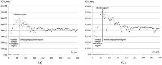
Figure 4.
“Contact strength—penetration depth” mechanical curves: (a) CG + TiVN; (b) UFG + TiVN.
- -
- the region of surface defect nucleation (the left-hand portion of the curve where stresses grow);
- -
- the inflection points at the maximum values of stresses that in this case have a sense of the ultimate contact stress (σIII);
- -
- the region of defect propagation (the right-hand portion of the curve) where cracks, cleavages, etc., are formed.
Comparison of the obtained “contact strength—penetration depth” curves (Figure 4) allow one to suppose that up to a penetration depth of Pd = 50 μm the coatings on both samples undergo elastic deformation, without the formation of cracks or cleavages. With increasing penetration depth, brittle defects start to emerge in the coating material, and it gradually fractures. The highest value of ultimate contact stress, σIII = 7.36 GPa, is observed in the UFG Ti alloy sample with a TiVN coating, which is also characterized by the highest value of the critical load Lc2 and, consequently, the best adhesive strength.
3.4. Erosion Test Results
From the results of the erosive wear tests, the dependencies of the decrease in the mass of the tested samples on the amount of the abrasive substance that acted upon them were plotted. The curves show the zones of restricted (a-b) and normal (b-c) wear, which differ in the rate of material loss, determined by the slope of the curves to the X axis.
In the zones of restricted wear (zones a-b, Figure 5) the coating material under the influence of abrasive particles loses its strength and gradually fractures to the base material.
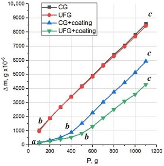
Figure 5.
Erosive wear of coatings with zones of restricted (a–b) and normal (b–c) wear.
As the coating fractures, the erosive wear rate increases and becomes approximately equal to the wear rate of the uncoated base material—the VT8M-1 alloy (zones b-c). This moment of time determines the period of normal wear when the wear rate of the samples becomes constant and equal to the wear rate of the base material without a coating.
Table 2 lists the erosion rates for each specimen, as well as the values of residual internal stresses in the TiVN coating on different substrates.
Table 2.
Erosion rate and residual stresses of the coatings.
The average erosion rate for each coating was determined in the period of normal wear (zones a-b) according to the ratio [11]:
where mf is the mass of the coated sample; mt is the sample weight at a time t during normal wear; At is the amount of abrasive spilled on the sample in a time t; va is the speed of the abrasive flow, g/min.
It can be seen from the presented Table 2 that there is a connection between the residual stresses acting in the coating and the erosion rate of the specimens, which confirms the previously made assumptions about the effect of internal stresses—the lower are the shear stresses in the multilayer PVD coatings, the higher is their erosion resistance [11].
Microscopic Studies of the Surface after the Erosion Tests
Figure 6 shows the samples in the UFG and CG structural state with a TiVN coating (UFG + TiVN and CG + TiVN, respectively) subjected to erosion tests. After testing for erosive wear, two areas are observed on coated specimens: an area of slight wear (golden color) and an area of maximum wear to the substrate (gray color). The area of slight wear on both samples is not of scientific interest for further research due to the absence of surface damage during the tests. At the same time, the gray area seems to be the most interesting to study, since the maximum wear was achieved in this area.
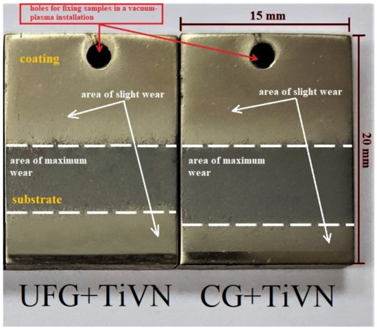
Figure 6.
Image of the samples after erosive wear tests.
On a sample with a UFG structure, the area of maximum wear is visually smaller due to a decrease in wear intensity as a result of increased adhesive strength of the coating to the substrate compared to a CG state. The observed effect may indirectly indicate a higher resistance to erosive wear.
In order to account for the different magnitudes and characters of erosive wear in the CG and UFG states, the authors conducted the fractographic analysis of the worn surfaces (area of maximum wear in Figure 6) after the erosion tests using a scanning electron microscope. It was found that the fracture of the samples with a UFG structure mainly had a transcrystalline character with zones of intercrystalline fracture, while for the samples with a CG structure, the fracture was mainly intercrystalline and propagated along both interphase and intergranular boundaries (Figure 7a).
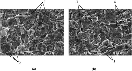
Figure 7.
SEM image showing the erosive wear of the VT8M-1 samples: (a) CG state; (b) UFG state; 1—intergranular boundaries; 2—interphase boundaries; 3—intercrystalline fracture zones; 4—slip bands; 5—brittle facets.
In the samples with a CG structure, brittle fracture prevails in the form of facets and a coarse-crystalline structure, as well as a zone of deformation slip with the formation of dimples and their chains. In the samples with a CG structure, the whole fractured surface is affected by discontinuities propagating along interphase and intergranular boundaries (Figure 7a).
In the samples with a UFG structure, the surface represents traces of deformation in the form of slip bands and ductile tongues transitioning into brittle facets. In the fractured surface, dimple discontinuities that do not transition into chains are uniformly distributed (Figure 7b).
In addition, a scanning electron microscope was used to study the wear profiles of the samples in the cross section (Figure 8) that has a wave-like facet character with different irregularity steps, Sm, from 19.02 μm for the samples in the UFG state to 22.99 μm for the CG samples.
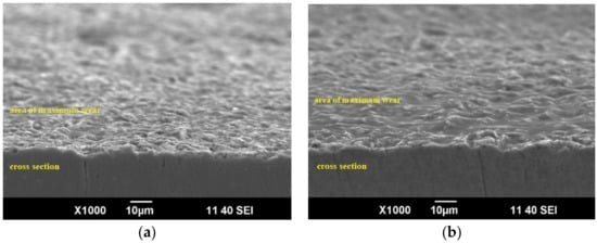
Figure 8.
SEM image showing the erosive wear of the VT8M-1 samples on cross sections: (a) CG state; (b) UFG state.
4. Discussion
At present, many ways are known for increasing the erosive wear resistance of metallic materials, but the most efficient way is the deposition of erosion-resistant protective coatings by ion-plasma methods. In particular, to protect the surface of the critical GTE parts made of Ti alloys, ion-plasma coatings deposited by physical vapor deposition (PVD) are widely applied, i.e., nitrides, carbides, carbonitrides based on refractory chemical compounds, e.g., with Zr, having an enhanced erosive wear resistance [6,7,11]. Currently, the enhancement of the performance reliability of critical parts made of Ti alloys is achieved by applying special erosion-resistant coatings that provide the required set of characteristics of the “metal/alloy—coating” system during operation. A combination of several unique properties of such coatings will enable using them for the protection of critical GTE parts from dust and gas-abrasive wear.
It is typically known that Ti alloys are used for making critical parts for aircraft-engine building [5,10], which are subjected to extreme loads and increased erosive wear. The structure refinement of Ti alloys by severe plastic deformation (SPD) processing and their surface modification by vacuum-plasma methods opens new opportunities for the production of structural materials with an enhanced set of performance properties [8,9].
As it follows from the results of the erosive tests, the deposition of the protective TiVN PVD coating onto the surface of the VT8M-1 titanium alloy in CG and UFG states considerably reduces the mass loss (Table 2). At the same time, the erosion resistance of the coated alloy with a UFG structure increases by a factor of 1.5 compared to the coated CG alloy (see also Table 1). Such a regularity was also reported in [18,19,20] for UFG Ti with a TiN coating.
Considering the impact and fatigue mechanism of fracture under the erosive action, the authors assume that the main parameters of a coating enhancing its wear resistance are the architecture (the quantity, thickness, and material of the layers) that determines the adhesive properties and the residual stresses that act at the “coating-substrate” interface. The authors also assume that the decisive role in the enhancement of the erosive wear resistance of coated metallic materials is played by the adhesive strength (the strength of adhesion) of a coating to the substrate which, as shown in the present study, is much higher in the alloy with a UFG structure. The UFG structure formation in the substrate material considerably increases the adhesive strength of the deposited coatings, which is apparently related to the increased number of crystallization centers during coating deposition, i.e., grain boundaries and crystalline structure defects in the substrate material. As it is known, in SPD-processed metallic materials, the density of grain boundaries grows significantly due to grain structure refinement.
In addition, an important factor that influences erosive wear resistance is the level of internal residual stresses in coatings. When surface erosion defects emerge, the shear stresses begin to act at the “coating-substrate” interface to compensate for residual normal stresses [6,7]. If the maximum shear stress exceeds the adhesive strength, the coating may peel off from the substrate and the erosion rate will increase.
In the present study, the residual stresses were evaluated by the sin2ψ X-ray method, and the presence of compressive stresses was revealed in the TiVN coating on both CG and UFG substrates. The level of residual stresses in the coating on the UFG substrate was lower than that in the coating on the CG substrate (−837 MPa and −928 MPa, respectively). The detailed studies of the effect of the level of internal residual stresses in coatings will be performed and described in our future works.
Microscopic studies revealed that the character of the erosive wear of the samples primarily depends on the structure of their base material. In the samples with a CG structure, the erosive wear of the coating has an intercrystalline character, propagating along intergranular and interphase boundaries, which corresponds to brittle fracture. In the samples where the substrate has a UFG structure, erosive wear has a transcrystalline character with local zones of intercrystalline fracture, slip bands, and brittle facets.
5. Conclusions
Thus, the performed research has revealed the following:
- An UFG structure with a mean grain size of 300 nm was successfully produced in the commercial Ti-5.7Al-3.8Mo-1.2Zr-1.3Sn-0.16Fe titanium alloy (the Russian grade VT8M-1) by SPD processing using rotary swaging.
- A comprehensive study of the architecture and properties of the TiVN protective PVD coating, deposited on the Ti alloy with a UFG and initial coarse-grained structures, was performed, and a significant effect of the grain refinement on the enhancement of erosive strength and wear resistance of the TiVN PVD coating was established. This effect is related to a significant increase in the adhesive strength of the protective coating on the UFG alloy, which was also found and investigated in the present work.
The obtained results suggest the good prospects of the complex approach to the enhancement of the erosive wear resistance of metallic materials, based on combining the UFG structure formation in the substrate and the application of a protective PVD coating, which creates new opportunities, in particular, for manufacturing gas turbine engine products for operation in extreme conditions.
Author Contributions
R.R.V.: conceptualization, writing the draft, and discussion of the results; K.S.S.: writing—review, editing, and performing the experiments; M.K.S., writing the draft and performing experiments; Y.M.D.: performing experiments; Y.N.S.: collection of data, writing the draft, and editing; R.Z.V., writing—review and editing; I.P.S., writing—review and editing. All authors have read and agreed to the published version of the manuscript.
Funding
The study of adhesion and contact strength of the coating, erosion tests, and study of the properties of the coating were performed with the financial support of the Russian Science Foundation, grant 19-79-10108. Savina Ya. N., for the microscopic examination of the surface after erosion tests, expresses her gratitude to the state assignment for the implementation of scientific research by laboratories (Order MN-8/1356 of 09/20/2021).
Institutional Review Board Statement
Not applicable.
Informed Consent Statement
Not applicable.
Data Availability Statement
Not applicable.
Acknowledgments
The authors are grateful to the personnel of the research and technology Joint Research Center, ’Nanotech’, Ufa State Aviation Technical University for their assistance with instrumental analysis.
Conflicts of Interest
The authors declare no conflict of interest.
References
- Valiev, R.Z.; Zhilyaev, A.P.; Langdon, T.G. Bulk Nanostructured Materials: Fundamentals and Applications; Wiley-Blackwell: Hoboken, NJ, USA, 2014; 456p. [Google Scholar] [CrossRef] [Green Version]
- Valiev, R.Z.; Estrin, Y.; Horita, Z.; Langdon, T.G.; Zehetbauer, M.J.; Zhu, Y.T. Producing bulk ultrafine-grained materials by severe plastic deformation: Ten years later. JOM 2016, 68, 1216–1226. [Google Scholar] [CrossRef] [Green Version]
- Semenova, I.P.; Valiev, R.Z.; Smyslov, A.M.; Pesin, M.V.; Langdon, T.G. Advanced materials for mechanical engineering: Ultrafine-grained alloys with multilayer coatings. Adv. Eng. Mater. 2021, 23, 2100145. [Google Scholar] [CrossRef]
- Zherebtsov, S.; Kudryavtsev, E.; Kostjuchenko, S.; Malysheva, S.; Salishchev, G. Strength and ductility-related properties of ultrafine grained two-phase titanium alloy produced by warm multiaxial forging. Mater. Sci. Eng. A 2012, 536, 190–196. [Google Scholar] [CrossRef]
- Leyens, C.; Peters, M. Titanium and Titanium Alloys: Fundamentals and Applications; John Wiley & Sons: Hoboken, NJ, USA, 2003. [Google Scholar]
- Rajendran, R. Gas turbine coatings—An overview. Eng. Fail. Anal. 2012, 26, 355–369. [Google Scholar] [CrossRef]
- Muboyadzhyan, S.A. Erosion-resistant coatings for gas turbine compressor blades. Russ. Metall. Met. 2009, 3, 3–20. [Google Scholar] [CrossRef]
- Semenova, I.P.; Valiev, R.R.; Selivanov, K.S.; Modina, Y.M.; Polyakov, A.V.; Smyslova, M.K.; Valiev, R.Z. Enhanced strength and scratch resistance of ultra-fine grained Ti64 alloy with (Ti+ V) N coating. Rev. Adv. Mater. Sci. 2017, 48, 62–70. [Google Scholar]
- Valiev, R.R.; Selivanov, K.S.; Modina, I.M.; Dyblenko, Y.M.; Semenova, I.P.; Valiev, R.Z. Architecture and Increased Adhesive Strength of Vacuum-plasma Coating on Ultrafine-grained Titanium Alloy. Adv. Eng. Mater. 2020, 22, 2000121. [Google Scholar] [CrossRef]
- Ilyin, A.A.; Kolachev, B.A.; Polkin, I.S. Titanium Alloys. Composition, Structure, Properties; VILS-MATI: Moscow, Russia, 2009. [Google Scholar]
- Selivanov, K.S.; Smyslov, A.M.; Dyblenko, Y.M.; Semenova, I.P. Erosive wear behavior of Ti/Ti (V, Zr) N multilayered PVD coatings for Ti-6Al-4V alloy. Wear 2019, 418, 160–166. [Google Scholar] [CrossRef]
- Modina, I.M.; Polyakov, A.V.; Dyakonov, G.S.; Yakovleva, T.V.; Raab, A.G.; Semenova, I.P. Peculiarities of microstructure and mechanical behavior of VT8M-1 alloy processed by rotary swaging. IOP Conf. Ser. Mater. Sci. Eng. 2018, 461, 012056. [Google Scholar] [CrossRef]
- Smyslova, M.K.; Tamindarov, D.R.; Plotnikov, N.V.; Modina, I.M.; Semenova, I.P. Surface electrolytic-plasma polishing of Ti-6Al-4V alloy with ultrafine-grained structure produced by severe plastic deformation. IOP Conf. Ser. Mater. Sci. Eng. 2018, 461, 012079. [Google Scholar] [CrossRef]
- Nestler, K.; Böttger-Hiller, F.; Adamitzki, W.; Glowa, G.; Zeidler, H.; Schubert, A. Plasma electrolytic polishing—An overview of applied technologies and current challenges to extend the polishable material range. Procedia CIRP 2016, 42, 503–507. [Google Scholar] [CrossRef]
- Fischer-Cripps, A.C. Introduction to Contact Mechanics; Springer: New York, NY, USA, 2007; Volume 101. [Google Scholar]
- Betsofen, S.Y. X-ray diffraction methods for the determination of residual stresses in the surface layers with gradient structure. Mater. Sci. 2006, 42, 357–375. [Google Scholar] [CrossRef]
- Betsofen, S.Y.; Bannykh, I.O.; Sarychev, S.M. Formation of residual stress in steels and titanium alloys during ion nitriding. Russ. Metall. Met. 2006, 2006, 383–388. [Google Scholar] [CrossRef]
- Wang, C.T.; Escudeiro, A.; Polcar, T.; Cavaleiro, A.; Wood, R.J.; Gao, N.; Langdon, T.G. Indentation and scratch testing of DLC-Zr coatings on ultrafine-grained titanium processed by high-pressure torsion. Wear 2013, 306, 304–310. [Google Scholar] [CrossRef]
- Chen, Z.; Zhou, K.; Lu, X.; Lam, Y.C. A review on the mechanical methods for evaluating coating adhesion. Acta Mech. 2014, 225, 431–452. [Google Scholar] [CrossRef]
- Wang, C.T.; Gao, N.; Gee, M.G.; Wood, R.J.K.; Langdon, T.G. Processing of an ultrafine-grained titanium by high-pressure torsion: An evaluation of the wear properties with and without a TiN coating. J. Mech. Behav. Biomed. Mater. 2013, 17, 166–175. [Google Scholar] [CrossRef] [PubMed]
Publisher’s Note: MDPI stays neutral with regard to jurisdictional claims in published maps and institutional affiliations. |
© 2022 by the authors. Licensee MDPI, Basel, Switzerland. This article is an open access article distributed under the terms and conditions of the Creative Commons Attribution (CC BY) license (https://creativecommons.org/licenses/by/4.0/).