Article

Microstructure and Performance of Al-Coating on AZ31 Prepared by Pack-Cementation with Different Heating Methods

1
College of Material Science and Engineering, Chongqing University of Technology, Chongqing 400054, China
2
Key Laboratory of Advanced Manufacturing Technology for Automobile Parts, Ministry of Education, Chongqing 400054, China
3
School of Materials and Energy, Southwest University, Chongqing 400715, China
4
College of Computer Science and Engineering, Chongqing University of Technology, Chongqing 400054, China
*
Authors to whom correspondence should be addressed.
Metals 2022, 12(5), 809; https://doi.org/10.3390/met12050809
Submission received: 7 April 2022 / Revised: 28 April 2022 / Accepted: 3 May 2022 / Published: 7 May 2022
(This article belongs to the Special Issue Surface Modification of Advanced Metallic Materials)

Abstract

:
In this study, Al-containing coatings were prepared on the surface of AZ31 magnesium alloy by pack-cementation through box-type furnace heating (BFH) and induction heating (IH) methods. Phases, microstructure, composition, and performance were characterized by X-ray diffraction technique (XRD), secondary electron imaging (SEI), backscattered electron imaging (BSEI), and energy dispersive spectroscopy (EDS), the Vickers hardness test and potentiodynamic polarisation test, respectively. The results show that the heating method has a significant impact on the phases, microstructure, thickness, and performance of the coatings. Both aluminized layers are relatively flat and dense, and no obvious second phase is observed. The thickness of the aluminized layer of the IH sample is much larger than that of the BFH sample because the diffusion rate of IH is greater than that of BFH. Both aluminized layers are composed of an outermost layer of β-Mg2Al3 and an inner layer of γ-Mg17Al12 near the side of the substrate. The evolution of different heating methods is discussed. The microhardness and corrosion behavior of the aluminized coatings were also investigated and discussed. The results indicate that the hardness and corrosion resistance of the IH diffusion sample is better than that of the BFH, and this is related to the content of the intermetallic compound phase.

1. Introduction

Magnesium alloys are the lightest metallic structural materials with high specific strength, good thermal conductivity, good machinability, and high recycling potential. They are widely used in aerospace, the automotive industry, electronic products, and other fields [1,2,3,4]. However, the poor surface performance of magnesium alloy, including low electrode potential and weak corrosion resistance, greatly restricts its application [5,6]. To expand the application of magnesium alloys, surface modification processes such as plasma electrolytic oxidation [7], physical vapor deposition [8], thermal spraying technology [9], chemical conversion coatings [10], and laser surface treatment [11] have been applied to improve the surface properties of magnesium alloy.
Compared with other processes, diffusion of alloying elements on the surface of the material is a series of very effective surface protection methods, which can improve the overall performance of the material’s surface hardness and corrosion resistance without damaging its original performance [12,13,14,15]. Among these methods, pack-cementation is widely applied to the surface diffusion process of metals and alloys due to its simple operation and affordability [16]. For magnesium alloys, the formation of Al–Mg or Zn–Mg intermetallic compounds on the surface of the magnesium alloy substrate can improve the corrosion resistance of the magnesium and the magnesium alloy parts [17]. Among the two compounds, the formation of Al–Mg on the surface of magnesium alloy is a more efficient and practical treatment method [18]. Shigematsu et al. [19] prepared an Al-rich layer on AZ91D using Al powder and ZrO powder as diffusion sources and obtained an Al–Mg intermetallic compound at a temperature of 450 °C; this is considered to be slightly too high, as this temperature will cause the magnesium alloy matrix to become partially melted. Therefore, temperature reduction in magnesium alloy production and improvement in the diffusion efficiency of the coating are the focus of current research.
Induction heating (IH) diffusion is regarded as one of the most promising methods, thanks to its simple application and good reproducibility compared with other processes, such as box-type furnace heating (BFH). Studies have shown that using the molten-salt system (AlCl3-NaCl) as the diffusion source can effectively reduce the diffusion temperature [18,20]. Therefore, it is meaningful to study the use of IH to further enhance the performance of coatings prepared by the molten-salt system. In this study, in order to improve the surface properties of the magnesium alloy, AlCl3-NaCl was used as a diffusion source. AZ31 magnesium alloy, as base material, was packed aluminizing through BFH and IH. Then, the microstructures, formation, and properties of the two coatings were investigated, and properties including microhardness and corrosion resistance were studied and compared.

2. Experiments and Methods

2.1. Sample Preparation

AZ31 magnesium alloy with a chemical composition (wt%) of 3.05% Al, 1.05% Zn, 0.42% Mn, 0.04% Si, 0.01% Cu, 0.003% Fe, 0.001% Ni, and Mg in balance was selected as the raw material. Before aluminizing, the base material was cut to a gauge dimension of 25 × 20 × 7 mm. Then, the specimens were ground by SiC papers to 3000 grit and ultrasonically cleaned in acetone solution.
The powder composition for aluminizing was 50% AlCl3 (molar ratio, and hereafter) as Al feedstock, 50% NaCl as the activator. These two powders form a molten salt system [21]. The diameter of all powders was less than 75 μm. The coating samples were prepared through box-type furnace and induction furnace heating, and named BFH and IH, respectively, based on the different heating methods. Prior to the aluminizing treatment, the mixed powders were thoroughly stirred, then put into a ceramic crucible (30 mL) and sealed with the mixture of refractory and sodium silicate. Then, the aluminizing treatment of both the BFH and IH samples was performed in a heating furnace at 400 °C for 1 h. After pack-cementation, all the samples were naturally cooled to room temperature in the furnace.

2.2. Characterization and Performance Test Methods

The phase components of coatings were identified by a Empyrean Series 2 X-ray diffraction instrument (PANalytical B.V., Almelo, The Netherlands) with Cu Kα radiation. The parameters were chosen as follows: voltage 40 kV, current 0.4 mA, angles range 20~90°, and step size 0.013°. Cross-sectional microstructures and morphologies of tempered and coated samples were observed using secondary electron imaging (SEI) and backscattering electron imaging (BSEI) detectors installed in a Zeiss Sigma HD field emission gun scanning electron microscope (Zeiss, Dresden, Germany). The AZtech Max2 energy dispersive spectroscopy (Oxford Instruments, London, UK), equipped in the FEG-SEM, was employed to characterize the distribution of various elements. Before microstructure characterization, the samples were ground by SiC papers to 3000 grit and then corroded with magnesium alloy etching solution (mixing equal amounts of ethanol, glacial acetic acid, and deionized water, and then adding picric acid until saturated).
The microhardness of the coated samples was determined by a HVS-1000Z automatic location table digital microhardness tester (Shanghai CSOIF Co., Ltd., Shanghai, China) equipped with a quadrangular pyramid indenter, using the parameters of load 0.5 N and a holding time of 10 s. The potentiodynamic polarization curves were tested in a 3.5% NaCl solution, using a Reference 3000 Gamry instrument (Warminster, Pennsyivania, PA, USA) to evaluate the corrosion behavior of the coated samples. Saturated calomel, platinum, and sample were used as the reference electrode, auxiliary electrode, and working electrode, respectively. The dynamic potential range was −1.8 to −1.0 V, and the scanning speed was 2 mV/s.

3. Results and Discussion

3.1. Phase Analysis

The XRD patterns of uncoated and coated samples are shown in Figure 1. The International Diffraction Data Center (ICDD) database was used to determine the phases. The Mg phase can be seen clearly on the XRD pattern of the as-received sample. After aluminizing treatment, the intensity of the diffraction peaks of Mg substrate is significantly reduced compared with the as-received sample. The peaks of Mg17Al12 and Mg2Al3 phases are observed both in the BFH and IH samples.
During the diffusion-reaction process, due to the difference in the stability of the concentration maintained between the packed powders and the matrix, the Al atoms with a certain activity of aluminizing agent atoms diffuse into the magnesium matrix [21]. As the diffusion reaction continues, the concentration of Al atoms continues to increase. According to the Al–Mg binary phase diagram [22], γ-Mg17Al12 will first form on the surface after the Al concentration exceeds its solid solubility, 12.7 wt%Al in Mg. When the concentration of Al in the surface layer continues to increase and exceeds 43.2 wt% Al, the β-Mg2Al3 phase will form. According to the content of the Al element, it can be judged that the β-Mg2Al3, with more Al, is closer to the outside of the coating, whereas the γ-Mg17Al12, with less Al, is closer to the substrate. It can also be seen from Figure 1, that the intensity of the diffraction peaks of Mg has been significantly reduced after aluminizing, which was caused by the recovery recrystallization experienced by the magnesium alloy in the furnace [23].

3.2. Microstructure Characteristics

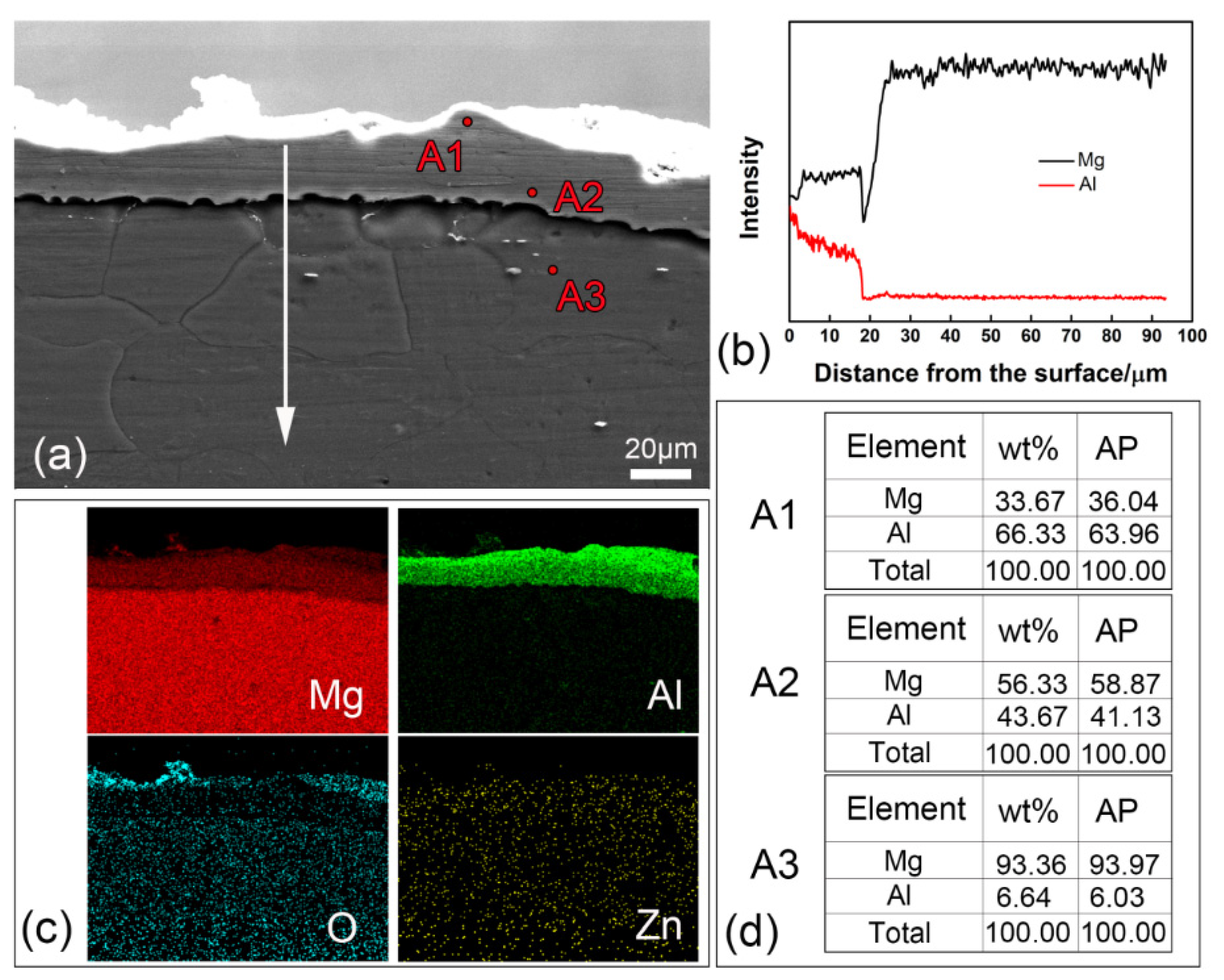
Figure 2 shows the cross-sectional microstructure of, and distribution of the elements in, the BFH sample. From Figure 2a, it can be seen that the average thickness of the Al-coating is less than 20 µm and the aluminized layer is relatively uniform. No obvious second phases were observed on the coating. The EDS line scan results in Figure 2b are the distribution of Mg and Al in the BFH sample along the arrow direction in Figure 2a. Within the thickness of the aluminized layer, the two elements of Mg and Al always existed together, whereas the concentration of Al atoms decreased along the depth direction, and the content of the Mg element was always higher than that of Al. This indicates that there is a phenomenon of mutual diffusion between the aluminized layer and the matrix.
Figure 2c shows the results of the EDS surface scan in Figure 2a. The element distribution in the aluminized layer and matrix can be observed. It can be seen that the Al-rich phase of the aluminized layer can be divided into two layers, the one closer to the outside is brighter, and the layer closer to the Mg substrate is darker. The results of the point scan in Figure 2d show that the content of the Al element decreases with the depth of the aluminized layer towards the matrix, and the atomic percentage of the Al element in the matrix (point A3) is only 6.03%. By analyzing and comparing the ratio of the amount of Mg and Al element substances in point A1 and point A2, combined with the above-mentioned XRD phase analysis and Al–Mg binary phase diagram [24], it can be judged that point A1 is the Mg2Al3 phase, and point A2 is Mg17Al12 phase. This adds further evidence that the aluminized layer of the BFH sample is composed of the outermost β-Mg2Al3 layer and the innermost γ-Mg17Al12 layer. Compared with other types of coatings on Mg alloy, such as PEO coatings, the pack-cementation coatings are dense and without the need for a subsequent processing or addition of borosilicate glass to the base electrolyte to seal the pores in the coatings [7].
Figure 3 shows the cross-sectional microstructure of, and distribution of the elements in, the IH sample. It can be seen that there is an obvious diffusion layer on the outside of the AZ31 magnesium alloy matrix. The structure of the aluminized layer is similar to that of the BFH sample. There is no obvious boundary between the aluminized layer and the matrix, which means that the combination of the aluminized layer and the matrix is relatively tight.
The heat source used in IH is of the internal type; therefore, the temperature gradient during Al diffusion is opposite to that of BFH. The temperature of the IF sample surface is always higher than that of the diffusing agent, which is extremely favorable for the generation, adsorption, and diffusion of active Al atoms. It can be seen that the thickness of the aluminized layer of the IH sample is about 35 µm, according to Figure 3a,b, which is much larger than that of the BFH sample. This shows that the diffusion rate of IH is greater than that of BFH. In addition, Figure 3c,d shows that the proportion of the β-Mg2Al3 layer in the aluminized layer is greater than that in BFH sample. That is to say, in the IH sample, more β-Mg2Al3 is formed, which is due to the higher degree of diffusion alloying in the IA-1 sample [25].

3.3. Formation of the Al–Mg Coatings

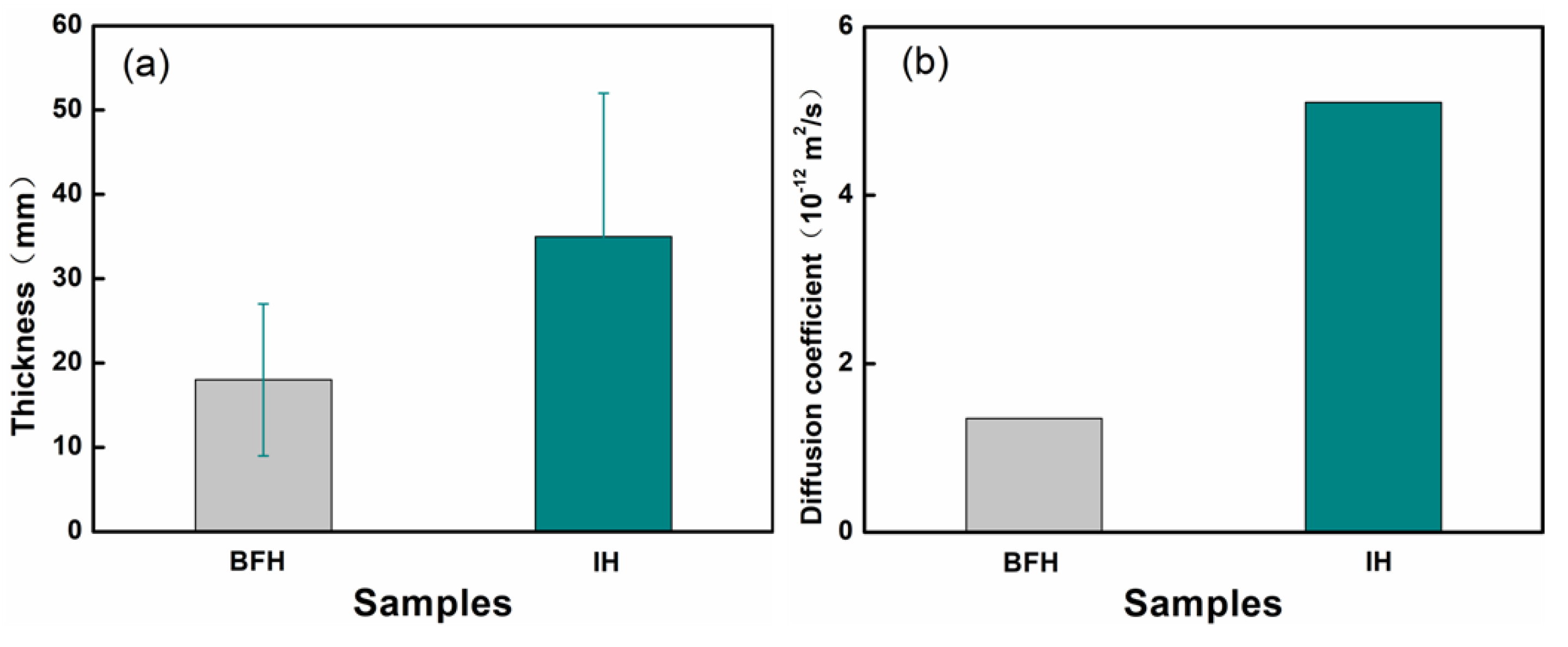
Figure 4a shows the thickness of the aluminized layer of the two specimens. The aluminized layer thickness of the IH sample is about 35 μm, which is nearly twice that of the BFH sample (18 μm). The reason for this phenomenon is the heating rate diffusion coefficient difference between IH and BFH [26]. Typically, the diffusion coefficient can be calculated based on diffusion distance, from the equation [27]:
D = d 2 4 t
where D is the diffusion coefficient, d is the diffusion distance (the thickness of Al-coating in this study) and t is the heating time. Thus, the diffusion coefficient of the BFH sample is 3.15 × 10⁻¹² m2/s, whereas that of IH is 5.10 × 10⁻¹² m2/s. The improvement in the diffusion efficiency of the IH sample is possibly related to atom electromigration, because of the electromagnetic effect in the induction heating furnace [26,28].
Figure 5 shows the formation of the aluminized layer structure. In this experiment, the embedded powder formed a molten salt system [29]. At lower temperatures, the high activity of Al in the molten salt helped the formation of aluminum alloy coatings. In addition, in this study, the Al element exists in the form of an active Al ion [21]. For the molten salt system, AlCl3 will firstly react with NaCl to form NaAlCl4 [21,29]. Then the Mg matrix may undergo the following reaction with the molten salt to generate active Al atoms.
3Mg + 2NaAlCl4 → 2Al + 3MgCl2 + 2NaCl
According to the thermodynamic data [21], calculation of the Gibbs free energy from the equation (2) above, the variation formula ∆G = −461997 + 5.071t can be derived. Moreover, as the ∆G in this study (at the temperature (t) of 400 ℃) is far less than zero, the reaction of Equation (2) can occur spontaneously. Figure 5a shows the mutual diffusion process of the aluminizing agent powder and AZ31 magnesium alloy matrix. When aluminized at 400 °C, the Al ions are activated and diffuse between the filled Al powder and the magnesium matrix under the action of the chemical concentration gradient.
After the concentration of Al ion in magnesium exceeds the solid solution limit in the magnesium matrix, a layer of γ-Mg17Al12 will be formed (Figure 5b). As the concentration of diffusion Al continues to increase, β-Mg2Al3 will be formed in the outmost layer (Figure 5c). The formation process of the IH sample is the same as that of the BFH sample, but the difference is that the IH process has higher diffusion efficiency than that of BFH [26]. Therefore, the thickness of the IH sample aluminized layer is larger and the concentration of Al is higher than that of the BFH sample. Figure 5d shows Al/Mg ratio along the scanning line in the IH and BFH samples. It can be seen that the penetration depth and the concentration within the magnesium matrix are completely different due to the difference in the diffusion coefficient.

3.4. Performance

3.4.1. Microhardness

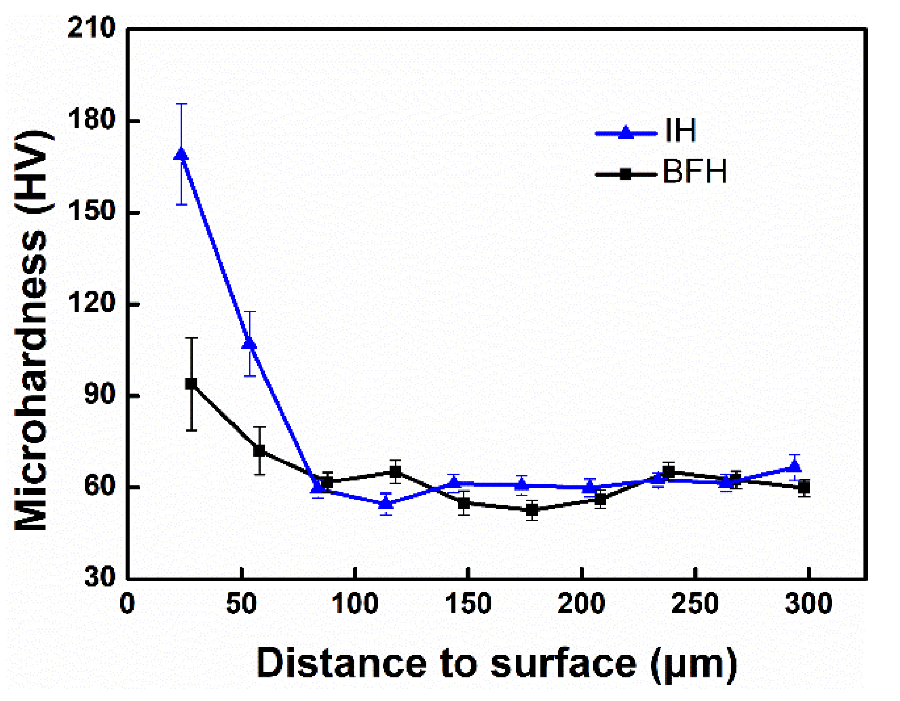
Figure 6 is the cross-sectional hardness distribution diagram of the samples from different heating methods. As shown in the figure, the hardness value of the BFH aluminized layer is about 94 HV, and the hardness of the IH aluminized layer is about 170 HV. The hardness of the aluminized layer of the two samples is much higher than the hardness value of the matrix (about 57 HV). This is because there are a large number of Al–Mg intermetallic compounds in the diffusion layer, and the Mg–Al intermetallic compound is composed of strong covalent bonds instead of metal bonds, which can significantly increase the hardness of the diffusion layer [30,31]. The hardness value is determined mainly by the kind and content of the intermetallic compound phase. The hardness of the aluminized layer of the IH sample is much higher than that of the BFH sample because a higher Al concentration leads to a higher content of β-Mg2Al3.

3.4.2. Polarization Test

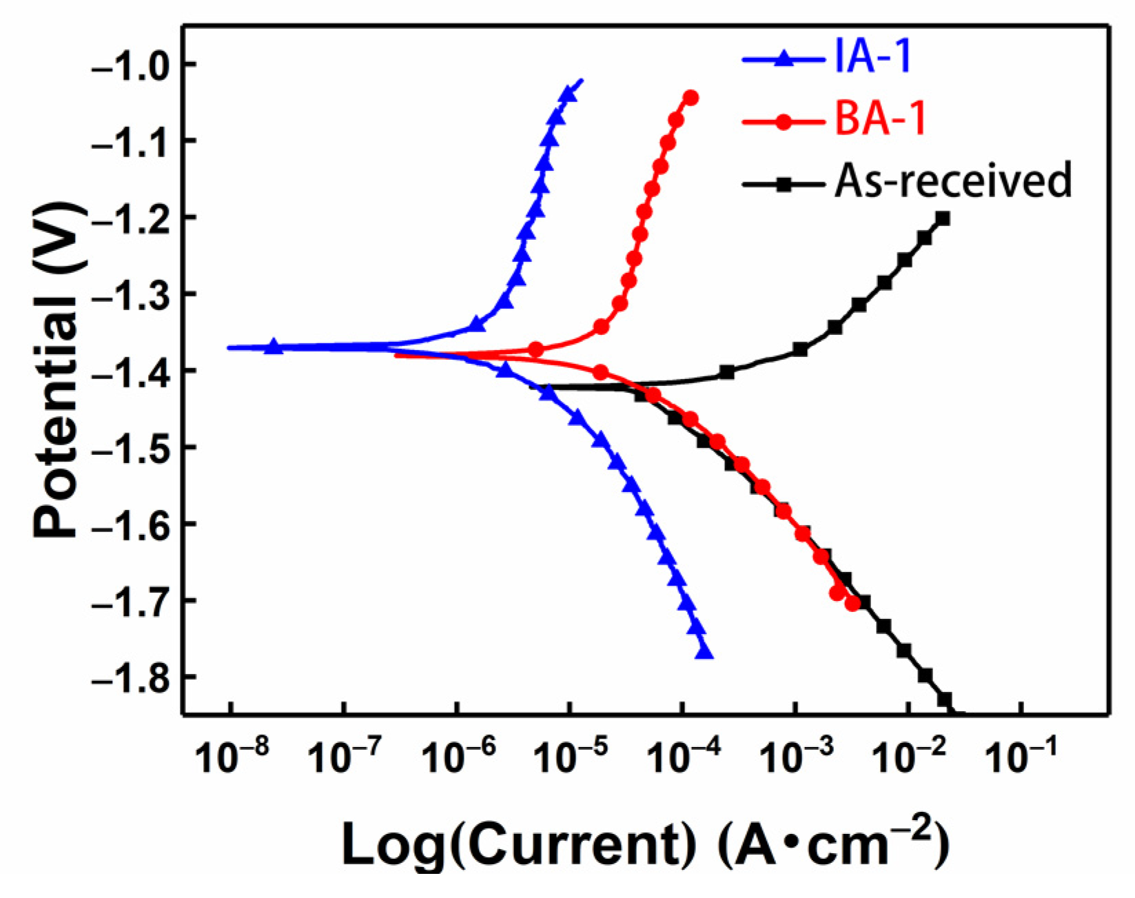
Figure 7 shows the dynamic potential polarization curves of AZ31 magnesium alloy before and after aluminizing. It can be seen that the polarization behavior of the alloy changes greatly. The polarization curve is composed of cathode hydrogen evolution and anode solution. The anode curve after aluminum plating has no obvious passivation. Since the self-corrosion potentials of Mg2Al3 and Mg17Al12 are higher than that of the Mg matrix [32], after aluminizing treatment, the self-corrosion potentials all became more positive, indicating that aluminizing treatment has a certain inhibitory effect on the anode reaction [33,34]. Table 1 shows the corresponding corrosion potential, corrosion current density, and corrosion rate of the samples in Figure 7, where the corrosion rate (CR) is calculated by Faraday’s equation [35].
The current corrosion data table shows that the self-corrosion current of the two samples has been reduced by more than an order of magnitude, and that the CR is significantly reduced, indicating that the corrosion resistance after aluminizing has been improved. Studies have shown that the corrosion resistance, in a sequence from high to low, proceeds from Mg2Al3, to Mg17Al12, and then matrix, so the presence of Mg17Al12 and Mg2Al3 can greatly delay and prevent the interaction between solution and matrix, and improve the corrosion resistance of magnesium alloy in Cl- environments [30]. This further illustrates that the Al–Mg coating can improve the corrosion resistance of AZ31 magnesium alloy, whereas the corrosion resistance of the IH sample is higher than that of the BFH sample.

4. Conclusions

Aluminized coatings were prepared on the surface of AZ31 magnesium alloy by pack-cementation with different heating methods. The phase composition, microstructure, performance, and formation were studied and analyzed. The main conclusions are as follows:
  • Both aluminized layers are relatively flat and dense, and no obvious second phase is observed. The coating is composed of the outermost β-Mg2Al3 layer and the γ-Mg17Al12 layer near the inner side of the substrate.
  • The diffusion efficiency of IH aluminizing is significantly higher than that of the BFH, and the coating thickness of the IH sample is twice that of the BFH sample.
  • Both coatings can effectively improve the surface hardness and corrosion resistance of the magnesium alloy. The hardness and corrosion resistance of the IH diffusion sample is better than that of the BFH, which is due to the content of the intermetallic compound phase.

Author Contributions

Conceptualization, J.H. and N.G.; methodology, J.L.; software, J.L. and P.J.; investigation, X.Y., X.H., H.L. and X.S.; resources, J.H.; data curation, J.H. and N.G.; writing—original draft preparation, X.Y. and J.L.; writing—review and editing, N.G.; supervision, X.H.; project administration, J.H. and N.G.; funding acquisition, J.H. All authors have read and agreed to the published version of the manuscript.

Funding

This work was co-supported by the Natural Science Foundation of China (51575073), Scientific and Technological Research Program of Chongqing (cstc2018jszx-cyzdX0126).

Institutional Review Board Statement

Not applicable.

Informed Consent Statement

Not applicable.

Data Availability Statement

All data included in this study are available upon request by contact with the corresponding author.

Conflicts of Interest

The authors declare that they have no conflict of interest.

References

  1. Mola, R.; Cieślik, M. Microstructure and properties of AZ31 with an Al/Si-enriched surface layer fabricated through thermochemical treatment. Surf. Coat. Technol. 2019, 374, 201–209. [Google Scholar] [CrossRef]
  2. Sun, A.; Sui, X.; Li, H.; Wang, Q. Interface microstructure and mechanical properties of zinc–aluminum thermal diffusion coating on AZ31 magnesium alloy. Mater. Des. 2015, 67, 280–284. [Google Scholar] [CrossRef]
  3. She, J.; Pan, F.S.; Guo, W.; Tang, A.T.; Gao, Z.Y.; Luo, S.Q.; Song, K.; Yu, Z.W.; Rashad, M. Effect of high Mn content on development of ultra-fine grain extruded magnesium alloy. Mater. Des. 2016, 90, 7–12. [Google Scholar] [CrossRef]
  4. Liu, G.D.; Xin, R.L.; Liu, F.Y.; Liu, Q. Twinning characteristic in tension of magnesium alloys and its effect on mechanical properties. Mater. Des. 2016, 107, 503–510. [Google Scholar] [CrossRef]
  5. Esmaily, M.; Blücher, D.B.; Svensson, J.E.; Halvarsson, M.; Johansson, L.G. New insights into the corrosion of magnesium alloys—The role of aluminum. Scr. Mater. 2016, 115, 91–95. [Google Scholar] [CrossRef] [Green Version]
  6. Doja, S.; Bichler, L.; Fan, S. Corrosion Behavior of AZ31 Magnesium Alloy in Highly Alkaline Environment. Acta Metall. Sin. Engl. Lett. 2017, 30, 367–375. [Google Scholar] [CrossRef] [Green Version]
  7. Pezzato, L.; Lorenzetti, L.; Tonelli, L.; Bragaggia, G.; Dabalà, M.; Martini, C.; Brunelli, K. Effect of SiC and borosilicate glass particles on the corrosion and tribological behavior of AZ91D magnesium alloy after PEO process. Surf. Coat. Technol. 2021, 428, 127901. [Google Scholar] [CrossRef]
  8. Chen, W.; Huang, J.; Peng, J. Characterisation of TiAlN PVD coatings on AZ31 magnesium alloy. Res. Chem. Intermed. 2015, 41, 1257–1266. [Google Scholar] [CrossRef]
  9. Jonda, E.; Atka, L.; Pakiea, W. Microstructure and Selected Properties of Cr3C2–NiCr Coatings Obtained by HVOF on Magnesium Alloy Substrates. Materials 2020, 13, 2775. [Google Scholar] [CrossRef]
  10. Zhou, X.H.; Chen, Q.R.; Wei, Z.L.; Yang, L.; Huang, Y.W. Chemical conversion coatings for magnesium alloys. Corros. Prot. 2004, 25, 468–482. [Google Scholar] [CrossRef]
  11. Yoon, S.; Kang, D.; Kim, J. Laser Surface Treatment of Magnesium Alloy using ZrO for Corrosion Resistance. J. Korean Soc. Manuf. Process Eng. 2016, 15, 93–100. [Google Scholar]
  12. Hu, J.J.; Zhang, Y.Q.; Yang, X.; Li, H.; Xu, H.B.; Ma, C.P.; Dong, Q.S.; Guo, N.; Yao, Z.W. Effect of pack-chromizing temperature on microstructure and performance of AISI 5140 steel with Cr-coatings. Surf. Coat. Technol. 2018, 344, 656–663. [Google Scholar] [CrossRef]
  13. Jiang, J.; Hu, J.J.; Yang, X.; Guo, N.; Xu, H.B.; Li, H.; Jin, Y.; Yu, H.B. Microstructure and annealing behavior of Cr-coatings deposited by double glow plasma on AISI 5140 steel. Results Phys. 2019, 15, 102674. [Google Scholar] [CrossRef]
  14. Ma, Y.P.; Li, J.; Zhu, J.; Yang, L.; Liu, Y.G.; Li, Z.Y.; Zhao, F. Effects of treatment time on corrosion of diffusion-alloyed coatings of pure magnesium. Acta Metall. Sin. Engl. Lett. 2007, 20, 72–78. [Google Scholar] [CrossRef]
  15. Mola, R. The properties of Mg protected by Al- and Al/Zn-enriched layers containing intermetallic phases. J. Mater. Res. 2015, 30, 3682–3691. [Google Scholar] [CrossRef]
  16. Zandrahimi, M.; Vatandoost, J.; Ebrahimifar, H. Pack Cementation Coatings for High-Temperature Oxidation Resistance of AISI 304 Stainless Steel. J. Mater. Eng. Perform. 2012, 21, 2074–2079. [Google Scholar] [CrossRef]
  17. Nassif, N.; Ghayad, I. Corrosion Protection and Surface Treatment of Magnesium Alloys Used for Orthopedic Applications. Adv. Mater. Sci. Eng. 2013, 2013, 346–349. [Google Scholar] [CrossRef] [Green Version]
  18. Calderón, D.; Galindez, Y.; Toro, L.; Zuleta, A.A.; Echeverría, F. Intermetallic-Rich Layer Formation for Improving Corrosion Resistance of Magnesium Alloys. Met. Mater. Int. 2021, 28, 657–665. [Google Scholar] [CrossRef]
  19. Shigematsu, I.; Nakamura, M.; Saitou, N.; Shimojima, K. Surface treatment of AZ91D magnesium alloy by aluminum diffusion coating. J. Mater. Sci. Lett. 2000, 19, 473–475. [Google Scholar] [CrossRef]
  20. Le, J.J.; Liu, L.; Liu, F.; Deng, Y.D.; Zhong, C.; Hu, W.B. Interdiffusion kinetics of the intermetallic coatings on AZ91D magnesium alloy formed in molten salts at lower temperatures. J. Alloy. Compd. 2014, 610, 173–179. [Google Scholar] [CrossRef]
  21. Zhong, C.; He, M.F.; Liu, L.; Chen, Y.J.; Shen, B.; Wu, Y.T.; Deng, Y.D.; Hu, W.B. Formation of an aluminum-alloyed coating on AZ91D magnesium alloy in molten salts at lower temperature. Surf. Coat. Technol. 2010, 205, 2412–2418. [Google Scholar] [CrossRef]
  22. Lu, D.; Zhang, Q.; Wang, W.; Guan, F.; Ma, X.; Yang, L.; Wang, X.; Huang, Y.; Hou, B. Effect of cooling rate and the original matrix on the thermal diffusion alloyed intermetallic layer on magnesium alloys. Mater. Des. 2017, 120, 75–82. [Google Scholar] [CrossRef]
  23. Schmitz, G.; Kruse, B.; Baither, D.; Kim, T.H. Concentration Characteristics of Diffusion-Induced Recrystallization. Defect Diffus. Forum 2009, 289–292, 719–724. [Google Scholar] [CrossRef]
  24. Okamoto, H. Supplemental Literature Review of Binary Phase Diagrams: Al-Mg, Bi-Sr, Ce-Cu, Co-Nd, Cu-Nd, Dy-Pb, Fe-Nb, Nd-Pb, Pb-Pr, Pb-Tb, Pd-Sb, and Si-W. J. Phase Equilibria Diffus. 2015, 36, 183–195. [Google Scholar] [CrossRef]
  25. Yang, H.; Guo, X.; Wu, G.; Wang, S.; Ding, W. Continuous intermetallic compounds coatings on AZ91D Mg alloy fabricated by diffusion reaction of Mg–Al couples. Surf. Coat. Technol. 2011, 205, 2907–2913. [Google Scholar] [CrossRef]
  26. Hu, J.J.; Zeng, J.; Yang, Y.; Li, H.; Guo, N. Microstructures and Wear Resistance of Boron-Chromium Duplex-Alloyed Coatings Prepared by a Two-Step Pack Cementation Process. Coatings 2019, 9, 529. [Google Scholar] [CrossRef] [Green Version]
  27. Takesue, S.; Kikuchi, S.; Misaka, Y.; Morita, T.; Komotori, J. Rapid nitriding mechanism of titanium alloy by gas blow induction heating. Surf. Coat. Technol. 2020, 399, 126160. [Google Scholar] [CrossRef]
  28. Shen, M.; Zhu, S.; Wang, F. A general strategy for the ultrafast surface modification of metals. Nat. Commun. 2016, 7, 13797. [Google Scholar] [CrossRef]
  29. Huang, W.M.; Xia, X.Y.; Liu, B.; Liu, Y.; Wang, H.W.; Ma, N.H. Electrodeposition of aluminum on aluminum surface from molten salt. Acta Metall. Sin. Engl. Lett. 2011, 24, 443–448. [Google Scholar]
  30. Li, X.; Liang, W.; Zhao, X.; Zhang, Y.; Liu, F. Bonding of Mg and Al with Mg–Al eutectic alloy and its application in aluminum coating on magnesium. J. Alloys Compd. 2009, 471, 408–411. [Google Scholar]
  31. Liu, F.; Meng, Q.; Li, Z. Microstructure and properties of alloying coating on AZ31B magnesium alloy. Trans. Nonferrous Met. Soc. China 2016, 26, 2347–2354. [Google Scholar] [CrossRef]
  32. Zhu, L.; Song, G. Improved corrosion resistance of AZ91D magnesium alloy by an aluminium-alloyed coating. Surf. Coat. Technol. 2006, 200, 2834–2840. [Google Scholar] [CrossRef]
  33. Liu, W.X.; Li, X.L.; Zhou, X.J. Formation Mechanism of Al and Zn Coating by Solid Diffusion on AZ81 Magnesium Alloy Surface. Surf. Technol. 2018, 47, 36–41. [Google Scholar]
  34. Hu, J.J.; Liao, J.; Yang, X.; Zeng, J.; Li, H.; Song, B.; Xu, H.B.; Guo, N.; Jin, Y. Microstructure and properties of Al-coating on AZ31 magnesium alloy prepared by pack-cementation. Trans. Nonferrous Met. Soc. China 2022, 32, 493–502. [Google Scholar] [CrossRef]
  35. Khara, S.; Choudhary, S.; Sangal, S.; Mondal, K. Corrosion resistant Cr-coating on mild steel by powder roll bonding. Surf. Coat. Technol. 2016, 296, 203–210. [Google Scholar] [CrossRef]
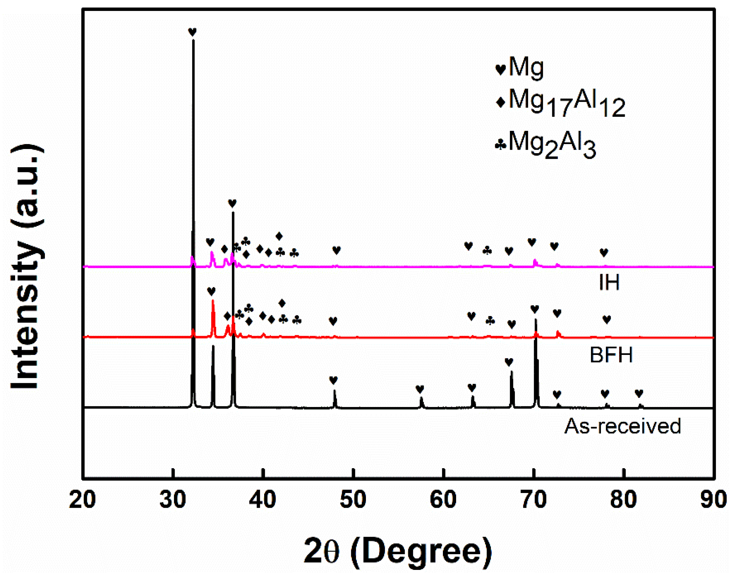
Figure 1. XRD patterns of various samples.
Metals 12 00809 g001
Figure 2. Microstructure and elements distribution of the BFH sample: (a) sectional SEI view of the coating; (b) EDS line scanning; (c) EDS mapping corresponds to the entire area in (a); (d) EDS point analysis of A1, A2, and A3 in (a).
Metals 12 00809 g002
Figure 3. Microstructure and element distribution of the IH sample: (a) sectional BSEI view of the coating; (b) EDS line scanning; (c) EDS mapping corresponds to the entire area in (a); (d) EDS point analysis of P1, P2, and P3 in (a).
Metals 12 00809 g003
Figure 4. Thickness (a) and diffusion coefficient (b) difference of different samples.
Metals 12 00809 g004
Figure 5. Formation of the aluminized layer structure. (a) diffusion process; (b) aluminizing process; (c) schematic illustration of the final structure after cooling; (d) Al/Mg ratio along the depth direction in the IH sample and BFH samples.
Metals 12 00809 g005
Figure 6. Microhardness and distance to sample surface.
Metals 12 00809 g006
Figure 7. Polarization curves of different samples.
Metals 12 00809 g007
Table 1. Corrosion potential (Ecorr), corrosion current density (Icorr), and average corrosion rate (CR).
SamplesEcorr (v)Icorr (A/cm2)CR (mm/y)
As-received−1.422.63 × 10−45.7654
IH−1.376.00 × 10−60.1315
BHF−1.384.24 × 10−50.9689
Publisher’s Note: MDPI stays neutral with regard to jurisdictional claims in published maps and institutional affiliations.