
High Strain Rate and Stress-State-Dependent Martensite Transformation in AISI 304 at Low Temperatures

 , , and
Abstract
1. Introduction
2. Materials and Methods
3. Results
4. Discussion
5. Conclusions
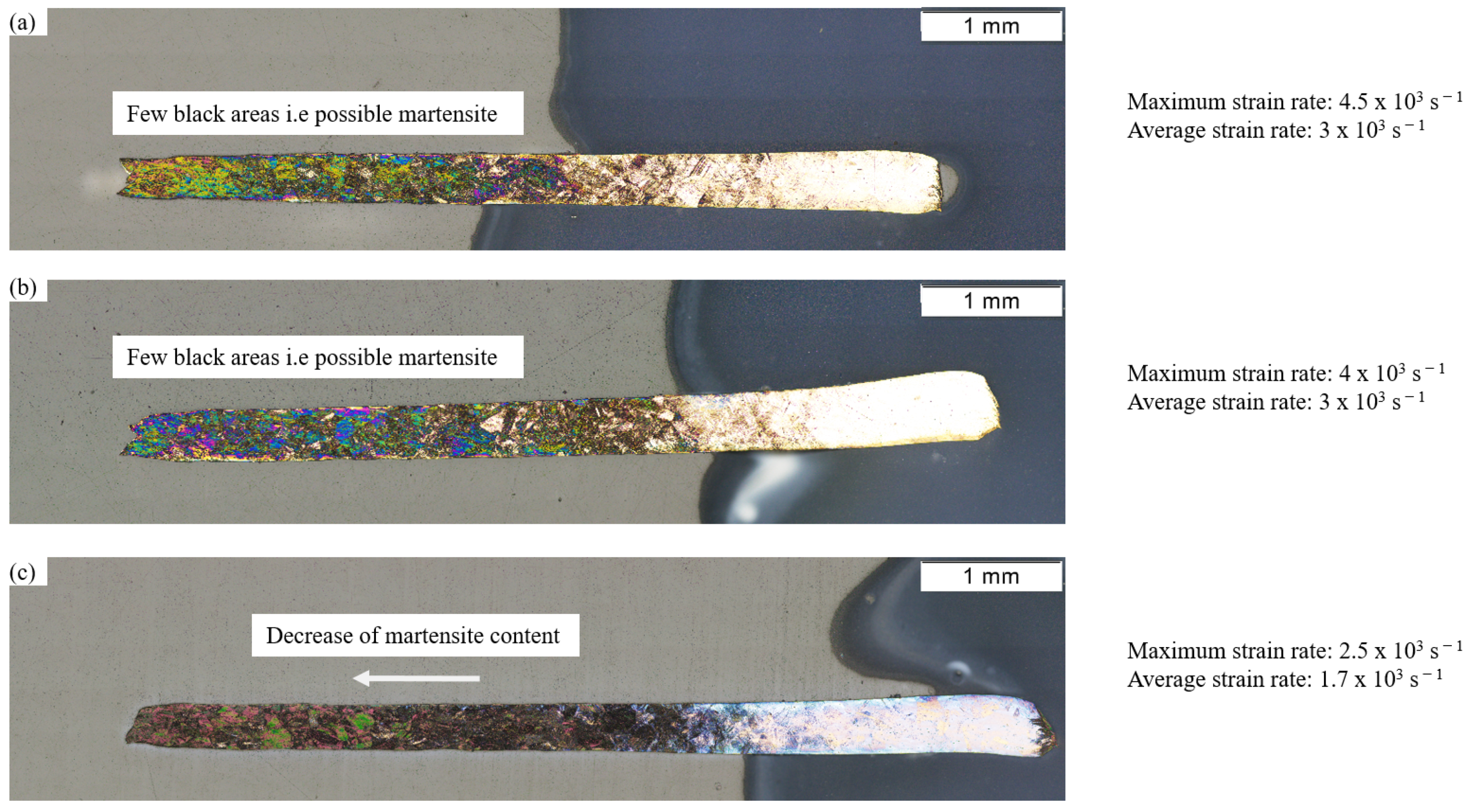
- With increasing strain rate, the -martensite transformation is suppressed under tensile loading. As described in the literature, this can be explained by an increase in adiabatic heating.
- Under shear loading, an increase in deformation-induced -martensite was found with increasing strain rate.
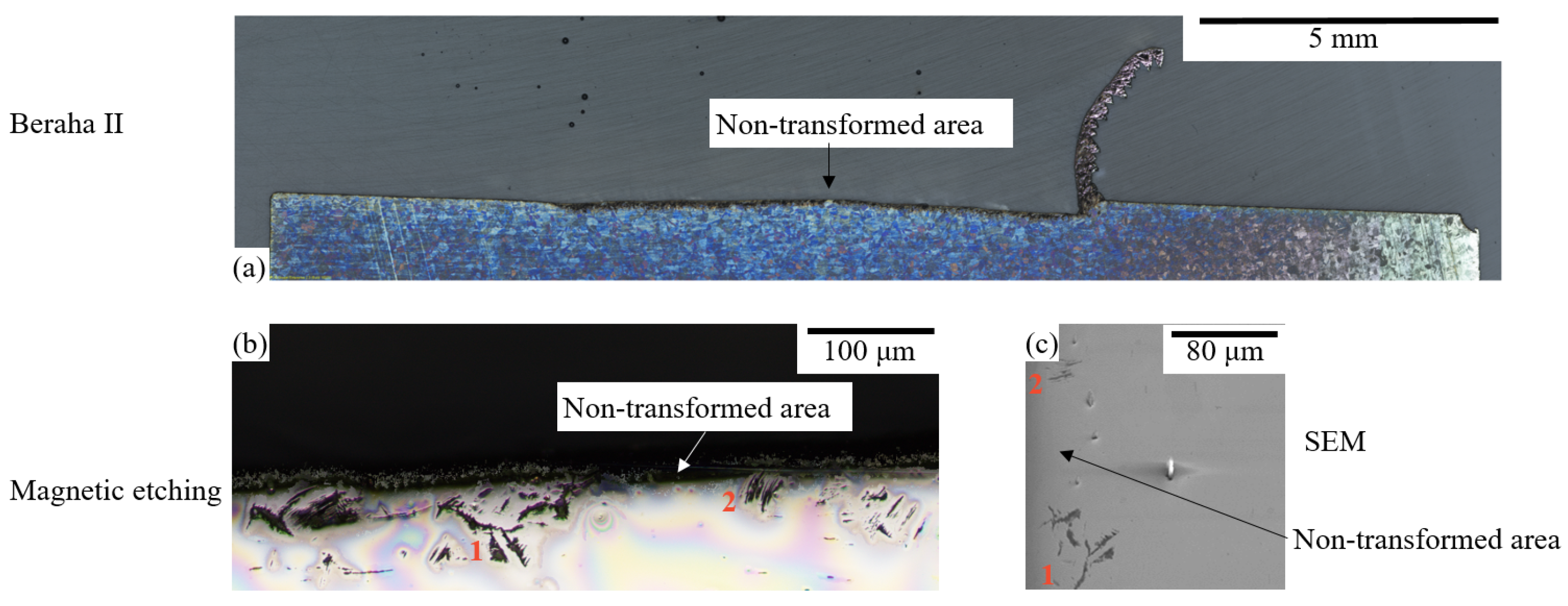
- For pure compressive loading, almost no -martensite transformation took place.
- Under a multiaxial stress state, which is present at the surface during a machining process, the highest -martensite transformation was observed. An increase in the -martensite content with increasing strain rate was found.
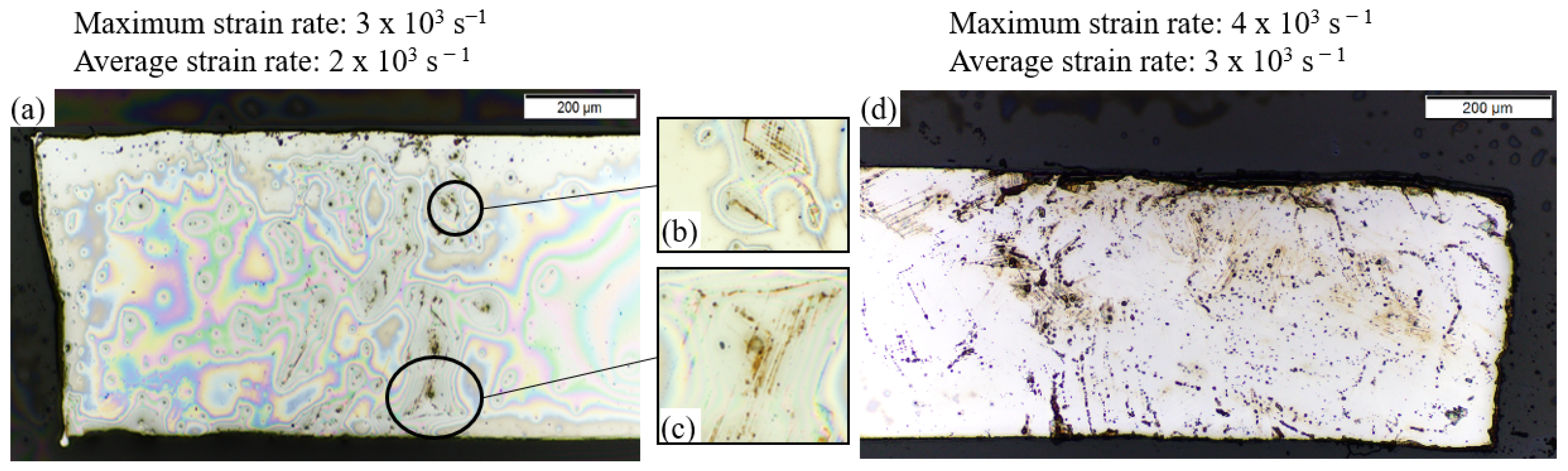
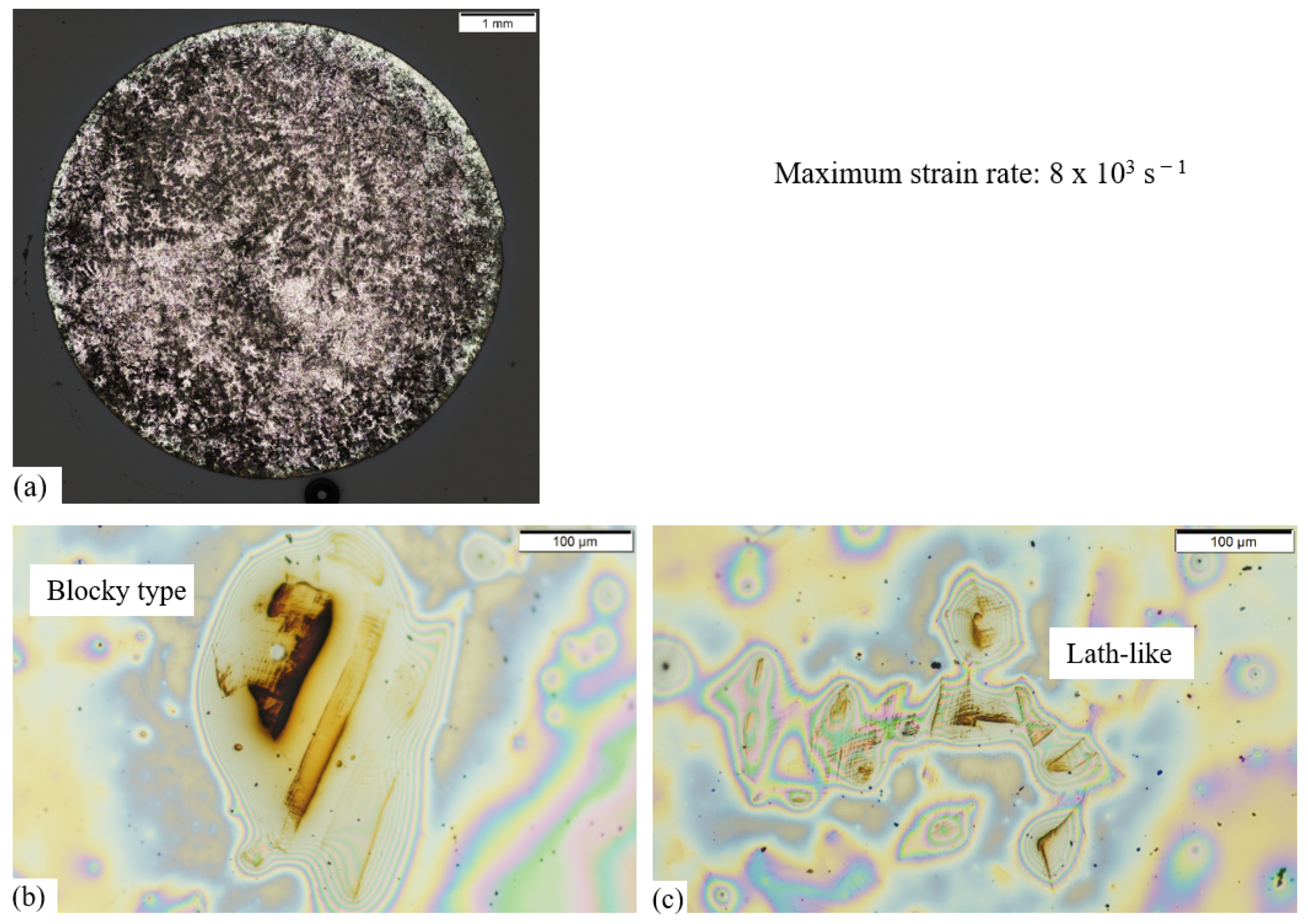
- Furthermore, under compressive conditions, in multiaxial systems and at high strain rates, a blocky -martensite was observed. Under shear stresses and lower strain rates, a lath -martensite was found. Since the subsurface of the specimens cut mainly exhibits a blocky -martensite and shear stresses support the martensitic transformation more than compressive stresses, the blocky -martensite seems to be due to the high strain rates and not due to compressive forces.
Author Contributions
Funding
Institutional Review Board Statement
Informed Consent Statement
Data Availability Statement
Acknowledgments
Conflicts of Interest
References
- Frölich, D.; Magyar, B.; Sauer, B.; Mayer, P.; Kirsch, B.; Aurich, J.; Skorupski, R.; Smaga, M.; Beck, T.; Eifler, D. Investigation of wear resistance of dry and cryogenic turned metastable austenitic steel shafts and dry turned and ground carburized steel shafts in the radial shaft seal ring system. Wear 2015, 328–329, 123–131. [Google Scholar] [CrossRef]
- Mayer, P.; Kirsch, B.; Müller, C.; Hotz, H.; Müller, R.; Becker, S.; von Harbou, E.; Skorupski, R.; Boemke, A.; Smaga, M.; et al. Deformation induced hardening when cryogenic turning. CIRP J. Manuf. Sci. Technol. 2018, 23, 6–19. [Google Scholar] [CrossRef]
- Hotz, H.; Smaga, M.; Kirsch, B.; Zhu, T.; Beck, T.; Aurich, J.C. Characterization of the subsurface properties of metastable austenitic stainless steel AISI 347 manufactured in a two-step turning process. Procedia CIRP 2020, 87, 35–40. [Google Scholar] [CrossRef]
- Hotz, H.; Kirsch, B. Influence of tool properties on thermomechanical load and surface morphology when cryogenically turning metastable austenitic steel AISI 347. J. Manuf. Process. 2020, 52, 120–131. [Google Scholar] [CrossRef]
- Hotz, H.; Kirsch, B.; Becker, S.; von Harbou, E.; Müller, R.; Aurich, J.C. Improving the surface morphology of metastable austenitic steel AISI 347 in a two-step turning process. Procedia CIRP 2018, 71, 160–165. [Google Scholar] [CrossRef]
- Fricke, L.V.; Nguyen, H.N.; Breidenstein, B.; Zaremba, D.; Maier, H.J. Eddy Current Detection of the Martensitic Transformation in AISI304 Induced upon Cryogenic Cutting. Steel Res. Int. 2020, 2, 2000299. [Google Scholar] [CrossRef]
- Fricke, L.V.; Gerstein, G.; Breidenstein, B.; Nguyen, H.N.; Dittrich, M.A.; Maier, H.J.; Zaremba, D. Deformation-induced martensitic transformation in AISI304 by cryogenic machining. Mater. Lett. 2021, 285, 129090. [Google Scholar] [CrossRef]
- Olson, G.B.; Cohen, M. A mechanism for the strain-induced nucleation of martensitic transformations. J. Less-Common Met. 1972, 28, 107–118. [Google Scholar] [CrossRef]
- Olson, G.B.; Cohen, M. A Perspective on Martensitic Nucleation. Annu. Rev. Mater. Sci. 1981, 11, 1–32. [Google Scholar] [CrossRef]
- Jaspers, S. Metal Cutting Mechanics and Material Behaviour. Ph.D. Thesis, Eindhoven University of Technology, Eindhoven, The Netherlands, 1999. [Google Scholar] [CrossRef]
- Krüger, L.; Wolf, S.; Martin, S.; Martin, U.; Jahn, A.; Weiß, A.; Scheller, P. Strain Rate Dependent Flow Stress and Energy Absorption Behaviour of Cast CrMnNi TRIP/TWIP Steels. Steel Res. Int. 2011, 82, 1087–1093. [Google Scholar] [CrossRef]
- Cao, B.; Iwamoto, T.; Bhattacharjee, P.P. An experimental study on strain-induced martensitic transformation behavior in SUS304 austenitic stainless steel during higher strain rate deformation by continuous evaluation of relative magnetic permeability. Mater. Sci. Eng. A 2020, 774, 138927. [Google Scholar] [CrossRef]
- Das, A.; Tarafder, S.; Chakraborti, P.C. Estimation of deformation induced martensite in austenitic stainless steels. Mater. Sci. Eng. A 2011, 529, 9–20. [Google Scholar] [CrossRef]
- Hecker, S.S.; Stout, M.G.; Staudhammer, K.P.; Smith, J.L. Effects of Strain State and Strain Rate on Deformation-Induced Transformation in 304 Stainless Steel: Part I. Magnetic Measurements and Mechanical Behavior. Metall. Mater. Trans. A 1982, 13, 619–626. [Google Scholar] [CrossRef]
- Eckner, R.; Krüger, L.; Motylenko, M.; Savinykh, A.S.; Razorenov, S.V.; Garkushin, G.V. Deformation mechanisms and microplasticity of austenitic TRIP/TWIP steel under flyer plate impact. Epj Web Conf. 2018, 183, 03007. [Google Scholar] [CrossRef]
- Denkena, B.; Tönshoff, H.K. Spanen–Grundlagen; Springer: Berlin/Heidelberg, Germany, 2011. [Google Scholar]
- Hopkinson, B. A method of measuring the pressure produced in the detonation of high explosives or by the impact of bullets. Proc. R. Soc. Lond. A 1914, 89, 411–413. [Google Scholar] [CrossRef]
- Chen, W.W.; Song, B. Split Hopkinson (Kolsky) Bar; Mechanical Engineering Series; Springer: New York, NY, USA, 2011; pp. 7–35. [Google Scholar] [CrossRef]
- Gama, B.A.; Lopatnikov, S.L.; Gillespie, J.W. Hopkinson bar experimental technique: A critical review. Appl. Mech. Rev. 2004, 57, 223–250. [Google Scholar] [CrossRef]
- Francis, D.K.; Whittington, W.R.; Lawrimore, W.B.; Allison, P.G.; Turnage, S.A.; Bhattacharyya, J.J. Split Hopkinson Pressure Bar Graphical Analysis Tool. Exp. Mech. 2017, 57, 179–183. [Google Scholar] [CrossRef]
- Larbi, S.; Djebali, S.; Bilek, A. Study of High Speed Machining by Using Split Hopkinson Pressure Bar. Procedia Eng. 2015, 114, 314–321. [Google Scholar] [CrossRef][Green Version]
- Zhang, Z.; Wang, Z.; Wang, W.; Jiang, R.; Xiong, Y. Investigation on surface quality of high-speed cutting titanium alloy Ti6Al4V based on Split-Hopkinson pressure bar. Proc. Inst. Mech. Eng. Part B 2020, 234, 1293–1301. [Google Scholar] [CrossRef]
- Berkovic, L.; Chabotier, A.; Coghe, F.; Rabet, L. Measuring and modeling of low temperature Hopkinson tests. Procedia Eng. 2011, 10, 1645–1650. [Google Scholar] [CrossRef][Green Version]
- Merklein, M.; Biasutti, M. Forward and Reverse Simple Shear Test Experiments for Material Modeling in Forming Simulations. In Proceedings of the 10th International Conference on Technology of Plasticity, ICTP 2011, Aachen, Germany, 25–30 September 2011; pp. 702–707. [Google Scholar]
- Olson, G.B.; Cohen, M. Kinetics of strain-induced martensitic nucleation. Metall. Trans. A 1975, 6, 791. [Google Scholar] [CrossRef]
- Gray, R.J. Magnetic Etching with Ferrofluid. In Metallographic Specimen Preparation: Optical and Electron Microscopy; McCall, J.L., Mueller, W.M., Eds.; Springer: Boston, MA, USA, 1974; pp. 155–177. [Google Scholar] [CrossRef]
- Talonen, J.; Aspegren, P.; Hänninen, H. Comparison of different methods for measuring strain induced α-martensite content in austenitic steels. Mater. Sci. Technol. 2004, 20, 1506–1512. [Google Scholar] [CrossRef]
- Schuhmann, H. Zur Metallographie der γ→ϵ→α - Umwandlung in hochlegierten Stählen. Prakt. Metallogr. 1967, 4, 265–283. [Google Scholar]
- Celada-Casero, C.; Kooiker, H.; Groen, M.; Post, J.; San-Martin, D. In-Situ Investigation of Strain-Induced Martensitic Transformation Kinetics in an Austenitic Stainless Steel by Inductive Measurements. Metals 2017, 7, 271. [Google Scholar] [CrossRef]
- Lee, W.S.; Lin, C.F. Morphologies and characteristics of impact-induced martensite in 304L stainless steel. Scr. Mater. 2000, 43, 777–782. [Google Scholar] [CrossRef]
- Murr, L.E.; Staudhammer, K.P.; Hecker, S.S. Effects of Strain State and Strain Rate on Deformation-Induced Transformation in 304 Stainless Steel: Part II. Microstructural Study. Metall. Mater. Trans. A 1982, 13, 627–635. [Google Scholar] [CrossRef]
- Asghari-Rad, P.; Shirazi, H.; Koldorf, S.; Nili-Ahmadabadi, M. Microstructure evolution of an Austenitic Stainless Steel severely deformed by the repetitive corrugation and straightening by rolling and subsequent annealing. In Proceedings of the 5th International Biennial Conference on Ultrafine Grained and Nanostructured Materials, Tehran, Iran, 11–12 November 2015; pp. 1–8. [Google Scholar]
- Totten, G.E. (Ed.) Steel Heat Treatment: Metallurgy and Technologies, 2nd ed.; CRC Taylor & Francis: Boca Raton, FL, USA, 2007. [Google Scholar]
- Jo, M.C.; Kim, S.; Suh, D.W.; Hong, S.S.; Kim, H.K.; Sohn, S.S.; Lee, S. Role of retained austenite on adiabatic shear band formation during high strain rate loading in high-strength bainitic steels. Mater. Sci. Eng. A 2020, 778, 139118. [Google Scholar] [CrossRef]
- Shrinivas, V.; Varma, S.K.; Murr, L.E. Deformation-induced martensitic characteristics in 304 and 316 stainless steels during room-temperature rolling. Metall. Mater. Trans. A 1995, 26, 661–671. [Google Scholar] [CrossRef]


Publisher’s Note: MDPI stays neutral with regard to jurisdictional claims in published maps and institutional affiliations. |
© 2022 by the authors. Licensee MDPI, Basel, Switzerland. This article is an open access article distributed under the terms and conditions of the Creative Commons Attribution (CC BY) license (https://creativecommons.org/licenses/by/4.0/).
Share and Cite
Fricke, L.V.; Gerstein, G.; Kotzbauer, A.; Breidenstein, B.; Barton, S.; Maier, H.J. High Strain Rate and Stress-State-Dependent Martensite Transformation in AISI 304 at Low Temperatures. Metals 2022, 12, 747. https://doi.org/10.3390/met12050747
Fricke LV, Gerstein G, Kotzbauer A, Breidenstein B, Barton S, Maier HJ. High Strain Rate and Stress-State-Dependent Martensite Transformation in AISI 304 at Low Temperatures. Metals. 2022; 12(5):747. https://doi.org/10.3390/met12050747
Chicago/Turabian StyleFricke, Lara Vivian, Gregory Gerstein, Andreas Kotzbauer, Bernd Breidenstein, Sebastian Barton, and Hans Jürgen Maier. 2022. "High Strain Rate and Stress-State-Dependent Martensite Transformation in AISI 304 at Low Temperatures" Metals 12, no. 5: 747. https://doi.org/10.3390/met12050747
APA StyleFricke, L. V., Gerstein, G., Kotzbauer, A., Breidenstein, B., Barton, S., & Maier, H. J. (2022). High Strain Rate and Stress-State-Dependent Martensite Transformation in AISI 304 at Low Temperatures. Metals, 12(5), 747. https://doi.org/10.3390/met12050747