1. Introduction
Ultrasonic impact treatment (UIT) is a very effective method for modifying the surface roughness and microstructure of parts and components made of steel, non-ferrous metals and alloys structural materials including welded joints [
1]. Their surface hardness, tribological and fatigue properties can be tailored over a wide range by changing UIT processing parameters. Depending on the operating conditions, UIT can lead either to surface smoothening of structural materials or to grain refinement in their surface layer, which of course, is accompanied by surface roughening. Generally, the higher impact forces applied during UIT resulted in higher compressive stresses, higher grain-boundary dislocation density, and larger crystal lattice distortions near the grain boundaries in the ultrasonically treated surface layer.
In our previous works [
2,
3,
4], it has been shown that the surface plastic deformation of commercially pure (CP) titanium during UIT occurs in the form of dislocation and grain boundary sliding, mechanical twinning, and strain-induced phase transformations. Unlike CP-Ti, the effect of UIT on the deformation behavior of the Ti-6Al-4V alloy which is the most widely used titanium alloy, particularly in aerospace applications, is not an actual research problem. UIT is not very effective for surface strengthening of the Ti-6Al-4V alloy, since the α/β structure significantly restricts dislocation motion, whereas the presence of aluminum in the α-Ti phase suppresses deformation twinning. The effect of strain-induced phase transformations on the mechanical behavior of the highly stable Ti-6Al-4V alloy is also negligible. UIT provides benefits only for weld joints of Ti-6Al-4V, since it induces compressive stress improving their fatigue properties [
5,
6,
7]. Moreover, the combination of UIT and Wire Arc Additive Manufacturing (WAAM) was recently proposed to improve the mechanical properties of Ti-6Al-4V parts [
8]. It is well-known, that the microstructure of additive-manufactured Ti-6Al-4V parts consists of coarse columnar prior β grains that is the dark side of 3D printing process [
9]. According to [
8], the UIT of each newly built layer of WAAM Ti-6Al-4V samples results in twice smaller equiaxed grains and a significant reduction in the residual stress.
Nevertheless, it is well-documented that structural and phase transformations in the Ti-6Al-4V alloy can occur during severe plastic deformation processing including UIT. According to [
10], grain refinement in the Ti-6Al-4V alloy under high-pressure torsion at room temperature is accompanied by hcp to fcc phase transformations due to the emission of partial dislocations from grain boundaries. Moreover, bcc to hcp phase transformation was reported to occur in the surface layer of Ti-6Al-4V samples subjected to UIT, which was primarily made possible due to changes in the electronic subsystem [
11].
Apart from the polymorphic transformations, changes in the phase composition of the surface layer of the Ti-6Al-4V alloy also happen during UIT. Due to the high reactivity of titanium, the formation of TiO
2 or TiN and Ti
2N phases was observed in the surface layer of Ti-6Al-4V during UIT at room temperature in air or at cryogenic temperatures in liquid nitrogen correspondingly [
12,
13]. Other drawbacks of titanium and its alloys which make their mechanical processing difficult are relatively high friction coefficient and strong susceptibility to seizure. Therefore, titanium samples are often lubricated with vacuum pump oil or graphite grease prior to the UIT to reduce friction. The chemical interaction of titanium with saturated hydrocarbons, which are components of lubricants, causes the nanosized carbide particles to form in the ultrasonically treated surface layer [
3]. It is worth noting that carbon-based lubricants are often used during UIT of structural materials. The saturation of the ultrasonically treated surface layer with carbon atoms not only contributes to the stabilization of nanosized ferritic grains but also causes the cementation reinforcement of steel samples.
Obviously, the interstitials (C, N and O) as well as concentration inhomogeneity of α- and β-stabilizing elements are well able to reduce lattice stability of the Ti-6Al-4V alloy resulting in the phase transformations in the ultrasonically treated uppermost surface layer. It’s obvious that such transformations are mainly associated with the β-phase. Since carbon, nitrogen and oxygen are α-stabilizers, they not only can lead to the formation of oxides, carbides and other compounds in the surface layer of titanium alloy under UIT, but are also able to compensate for the effect of β-stabilizers. The interstitials affect the electron structure of titanium causing its lattice transformation. However, the microstructural investigations of titanium alloys subjected to UIT are often focused on the evolution of dislocation density and grain structure [
6,
7], although the study of the strain-induced phase transformations should also yield both theoretical insight and practical results.
There is no doubt that it is difficult to study experimentally strain-induced phase transformations at the atomic scale due to the restriction of the experimental equipment. Explicit identifying the mechanisms of structural and phase transformations during repeated penetrations of a striker into the treated specimen is made possible by computer simulations, e.g., using molecular dynamics (MD) [
14]. Earlier, the MD simulation showed that diamond cubic silicon transforms into a body-centred tetragonal form (β-silicon) upon loading of the indenter [
15]. Similarly, Hua and co-authors [
16], have shown the formation of the HCP phase in the FCC matrix of a single crystal CoCrNi during nanoindentation [
16]. The authors of the article, using MD simulation, demonstrated the development of reversible β→α→β phase transformations in the Ti-6Al-4V titanium alloy during scratch testing, which made it possible to explain the experimentally observed recovery of a scratch [
17,
18,
19]. It has been found that the migration of the twin boundaries in the titanium crystallite under tension is also governed by the development of reversible α→β→α transformations [
20]. However, it remains to be seen how the significant fragmentation and disorientation of the crystal lattice in the ultrasonically treated surface layer affect the development of the strain-induced phase transformations in the Ti-6Al-4V alloy. In the present study, an experimental investigation, an MD simulation and an ab-initio calculation were used to reveal the mechanisms underlying the development of structural and phase transformations in the Ti-6Al-4V alloy during UIT.
2. Experimental and Numerical Procedures
Ti-6Al-4V titanium alloy plate was cut into dimensions of 100 mm × 100 mm × 1 mm square samples. The chemical composition of Ti-6Al-4V titanium alloy as examined using energy-dispersive spectroscopy is presented in
Table 1. The UIT processing of the plate was carried out using a spherical striker 10 mm in diameter rigidly fixed to the tip of the ultrasonic horn oscillating at a frequency of 22 kHz. The oscillation amplitude and impact load of the striker fabricated from the hard alloy (WC-8 wt.% Co) were 40 μm and 200 N, respectively. The ultrasonic treatment was performed in a row-by-row manner, so that the striker could move along the plate at a speed of 0.015 m/s, much like a typewriter. The image of a self-developed UIT device is shown in
Figure 1.
A JEM-2100 (JEOL, Akishima, Tokyo, Japan) transmission electron microscope (TEM) equipped with Inca ACT-X energy-dispersive spectroscopy (EDS) detector (Oxford Instruments, Concord, MA, USA) was employed for the microstructural characterization of the samples in the cross-section geometry. The cross-sectional TEM samples were prepared using a JEOL Ion Slicer EM-091001S focused ion beam system (JEOL, Akishima, Tokyo, Japan).
TEM image analysis was applied to estimate the scalar density of dislocations
ρ in the surface layer of the ultrasonically treated Ti-6Al-4V samples. The value of
ρ was determined by the rectangular grid method using the following expression:
where
and
are the numbers of intersections;
and
are the line lengths;
M is the magnification;
t is the TEM foil thickness.
The computer simulation of the UIT processing was carried out by successive triple indentations of a spherical indenter into an initially defect-free model titanium crystallite using the LAMMPS (Large-Scale Atomic/Molecular Massively Parallel Simulator) molecular dynamics code [
21]. The crystallite had the shape of a parallelepiped with dimensions of 75 × 51 × 19 nm along the X, Y and Z directions, respectively. In our previous work [
4], the indentation of a hexagonal close-packed titanium crystallite (α-phase) was performed, while in the present paper the indenter penetrated into a bcc Ti crystallite contained 20 at.% vanadium (β-phase). The indenter was a sphere with a radius R of 25 nm. The load value was calculated as F = −k(R − r)
2, where r was the distance between the centres of the indenter and atoms and k is the indenter stiffness coefficient. In our calculations, the parameter k was chosen to be equal to 10 eV/A
3 similar to the earlier works [
22,
23,
24]. The indenter was moved along the Z axis at a fixed depth of 5 nm with a constant rate of 15 m/s. The indentation depth was chosen so that the maximum load applied to the indenter did not exceed 12 GPa. The triple indentation of the model crystallite was simulated in such a way that each indentation resulted in the movement of the indenter along the X axis at a distance of 12.5 nm. This distance corresponds to the displacement of a treated titanium plate relative to an oscillating striker.
Crystallographic orientations of the model titanium crystallite were chosen as follows: the X, Y, and Z axes coincided with the [100], [010], and [001] directions, respectively. The equilibrium atomic configuration of the crystallite was determined from the calculation of the minimum potential energy. The interaction between atoms was described by the potential [
25] assessed within the framework of the modified embedded atom method. The simulated system was considered as an NVE ensemble, in which the number of atoms, energy and volume were conserved. The movement equations were integrated using the high-speed Verlet algorithm with a time step of 0.001 ps. The total number of atoms exceeded 4.3 million. The initial temperature of the simulation, 300 K, was achieved by using the velocity rescaling method during the MD simulation process from the balance between kinetic and thermal energies. The Common Neighbor Analysis (CNA) and Dislocation Extraction Algorithm (DXA) of the OVITO software [
26] were used to identify the crystal lattice defects produced by the multiple indentations. The simulation of strains of the model crystallite was carried out considering the nucleation and movement of dislocations along certain crystallographic planes. The calculations were performed using the SKIF-Cyberia supercomputer of Tomsk State University.
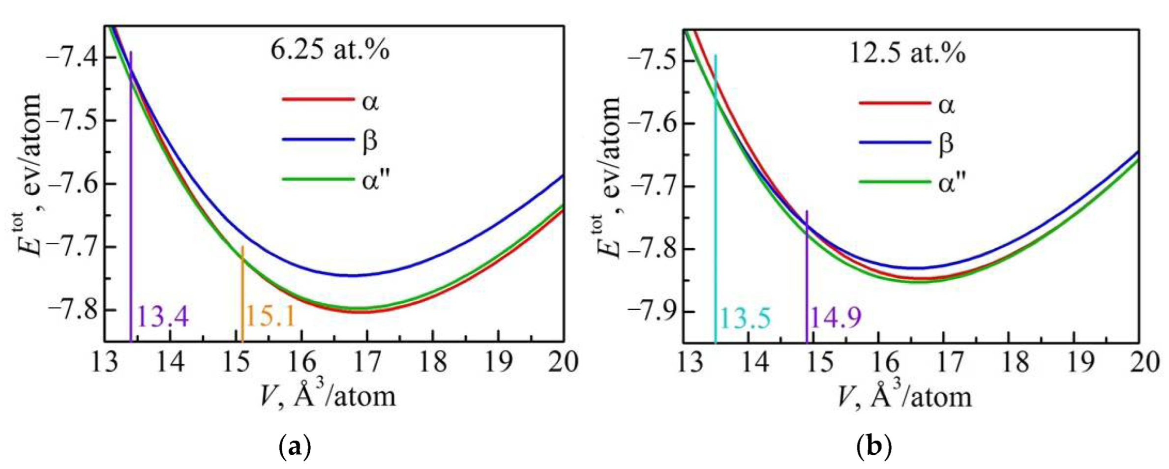
Ab initio calculation of the atomic structure of vanadium-alloyed α, β and α″ phases of titanium was performed by the projector augmented-wave method within the density functional theory [
27,
28]. For the exchange-correlation functional the generalized gradient approximation (GGA) in the form of PBE was used [
29]. A plane-wave cutoff energy of 300 eV was employed throughout the calculations. The hcp and bcc structures were calculated for Ti containing 6.25, 12.5, 18.75 and 25.0 at.% of V using a (2 × 2 × 2) supercell with the number of V atoms varied from one to four. Orthorhombic crystal structure with the same content of vanadium was calculated using a (2 × 1 × 2) supercell. The atomic positions and the volume of the supercells were optimized. The most preferred configurations of V atoms within the supercells were applied. The ab initio calculations of the total energy per atom as a function of atomic volume were carried out for Ti crystallites with α, β and α″ structures to reveal the effect of compression and tension developed during UIT.
3. Experimental Research Results of Changes in the Microstructure of the Ti-6Al-4V Sample during the UIT Processing
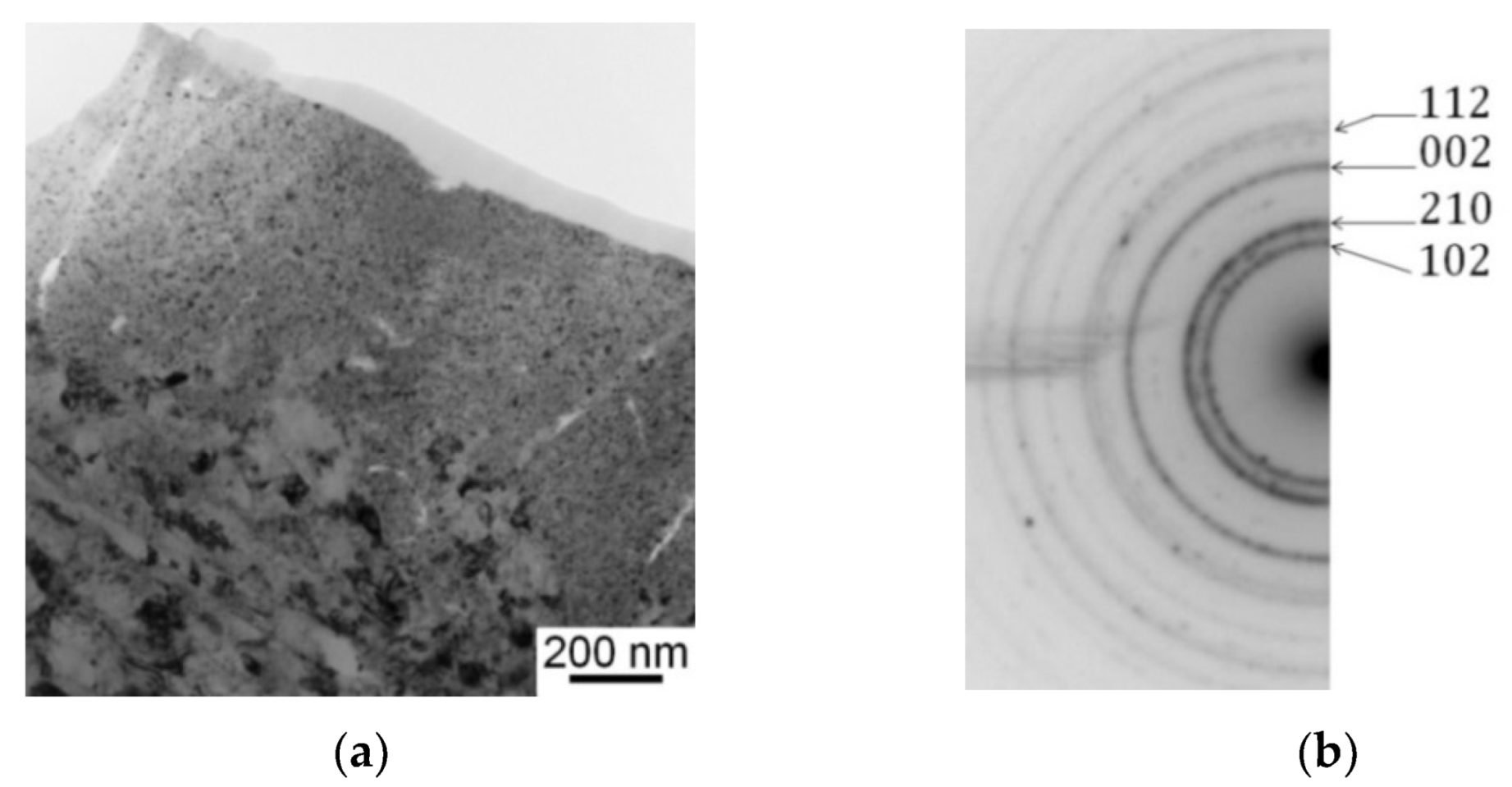
A cross-sectional TEM study of the Ti-6Al-4V samples subjected to UIT revealed a mixed amorphous and nanocrystalline structure within the 200 nm thick uppermost surface layer (
Figure 2a). The microstructure of the layer mainly consists of nanocrystalline titanium dioxide TiO
2, which is clearly confirmed by the ring structure of electron diffraction patterns (
Figure 2b). Low-indexed crystal planes of the TiO
2 phase presented in the SAED pattern are identified by Miller indices as (101), (210), (002) and (112) planes. More details concerning the results obtained using TEM and XRD are given elsewhere [
30].
Apart from the oxidation process, the refinement of α-Ti grains and β-Ti interlayers occurs during UIT leading to the formation of the multilayer microstructure in the surface layer of the Ti-6Al-4V samples.
Figure 3a exhibits the microstructure of a 5 µm thick highly deformed surface layer comprised of fine α-Ti grains with an average grain size of 100 nm. At a depth of 45 μm the ultrasonically treated surface layer exhibits the microstructure containing a fragmented α-Ti grain structure (
Figure 3b). Average transverse and longitudinal sections of the α-Ti grain size estimated from STEM images are 2 and 0.4 μm in length, respectively. Finally, at a depth of 75 μm the microstructure is similar to that observed in the as-received Ti-6Al-4V samples. The α-Ti quasi-equiaxed grains with a size of 2–5 µm are evidenced in
Figure 3c.
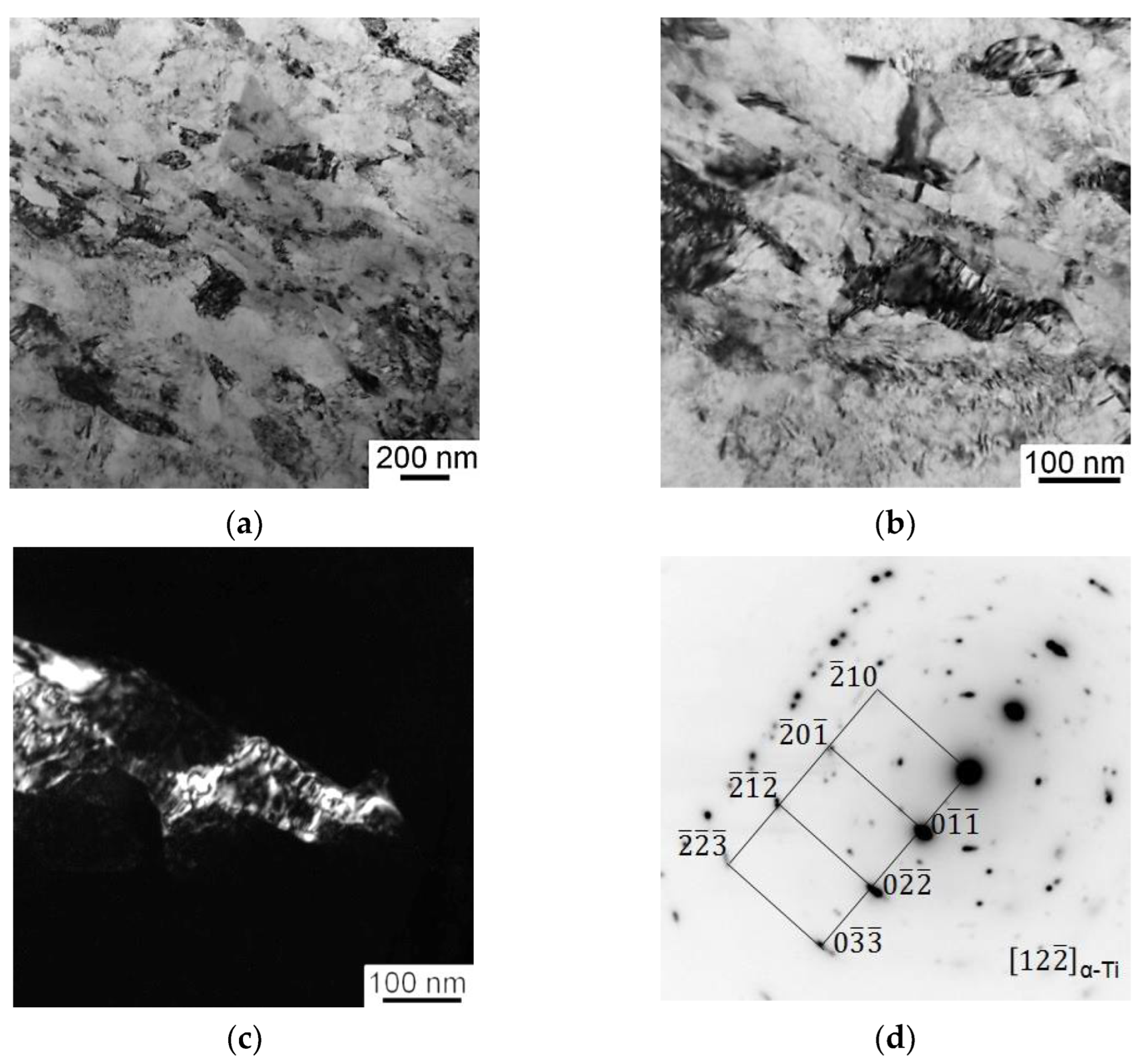
Detailed TEM studies demonstrate nonequiaxed fine α-Ti grains containing a large number of dislocations (ρ = 7.2 × 10
14 m
−2) at a depth of 5 μm below the treated surface (
Figure 4), where the deformation occurs through the ploughing mechanism [
31]. A comprehensive analysis of dark-field TEM images and an associated SAED pattern evidences the fact that the nanosized grains are separated by boundaries with low-angle misorientations. It is worth noting that β-phase precipitates were not found in the TEM investigations.
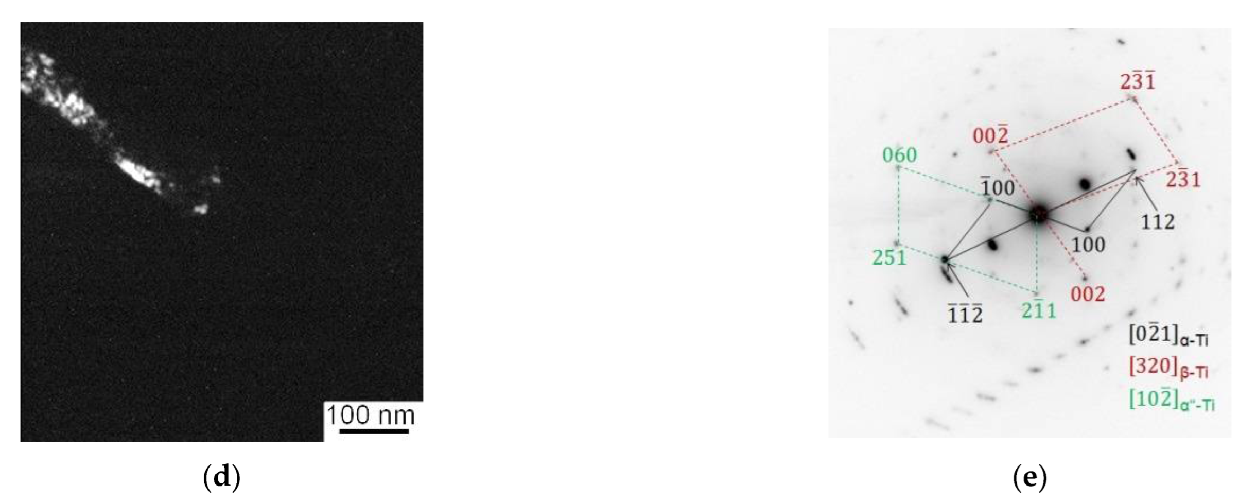
The microstructure of the lower layer located at a depth of 10 µm below the treated surface consists of α grains with an intragranular band structure (
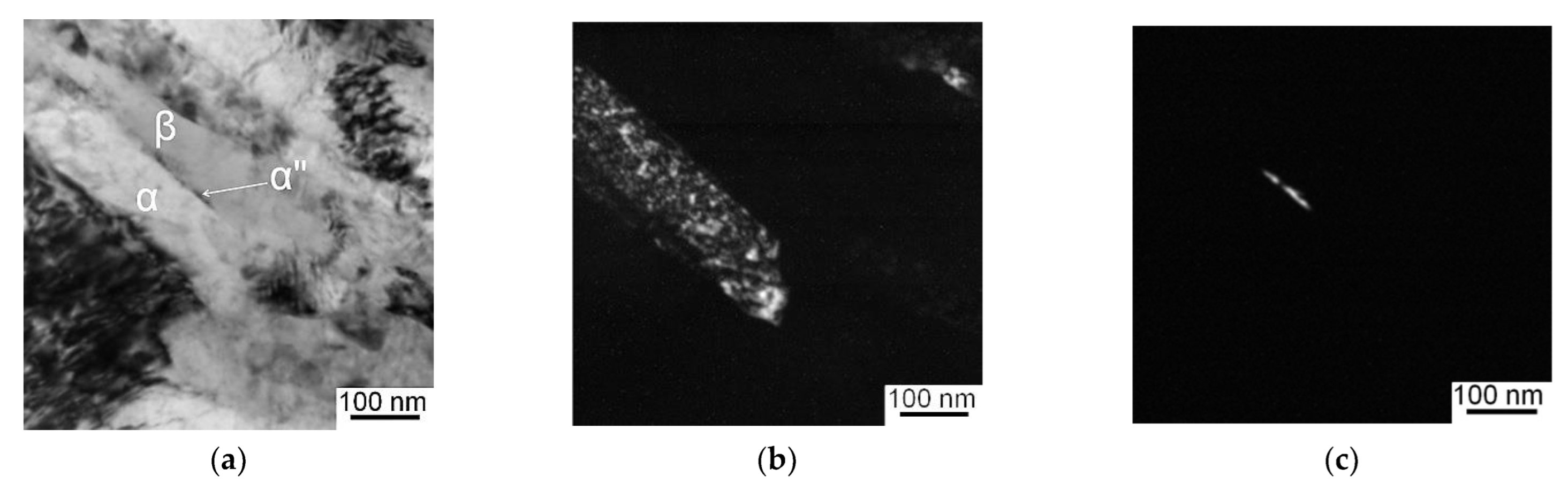
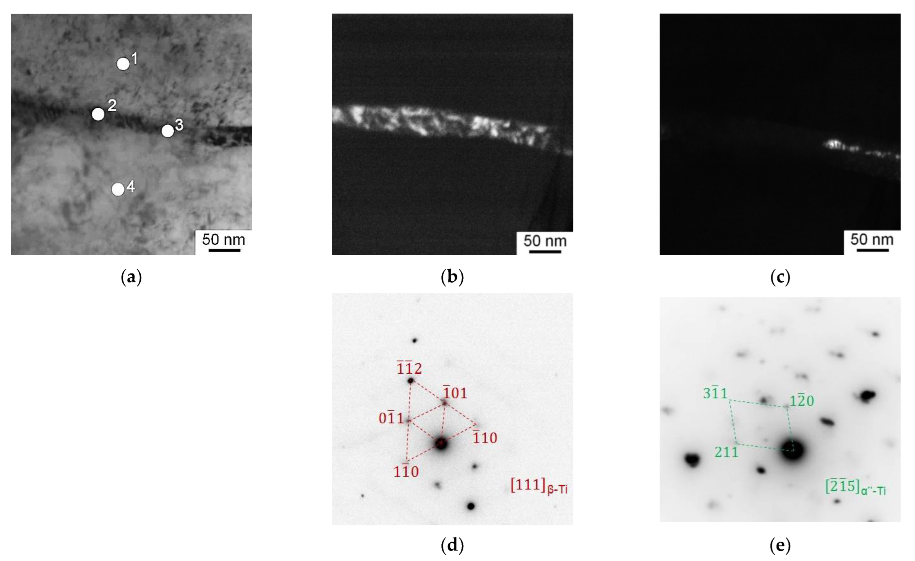
Figure 5). The average width of the elongated subgrains is equal to 100 nm. It is worth noting that the interlayers of the retained β phase are observed between α subgrains (
Figure 5d). Moreover, thin platelets (5–10 nm thick) of the orthorhombic (α″) martensite are observed at the boundaries between the α and β phases (
Figure 5c).
According to
Figure 6a, the enhanced translational movement in easy-sliding directions precedes less pronounced fragmentation of the original α grain structure at a depth of 45 μm below the treated surface. A marked difference in orientations between adjacent α-Ti subgrains is evidenced by dark-field TEM micrographs (
Figure 6b,c). The dislocation cell structure inside the elongated subgrains is visible.
The fragmentation of the retained β-Ti interlayers causing the misorientation between adjacent β-Ti subgrains is also observed at a depth of 45 μm below the treated surface (
Figure 7). Moreover, the refinement of the β-Ti phase is accompanied by the formation of the α″ martensitic phase. It is worth noting that the development of the β→α″ transformation occurs only in areas with high torsion of the Ti crystal lattice as well as in the presence of oxygen atoms.
The torsion curvature of the α phase crystal lattice estimated by assessing the bending extinction contours in the TEM micrographs (
Figure 7) reaches 6 deg/µm. As shown in
Table 2, the content of oxygen in the α-Ti grains and β-Ti interlayers varies from 15 to 27 at.%.
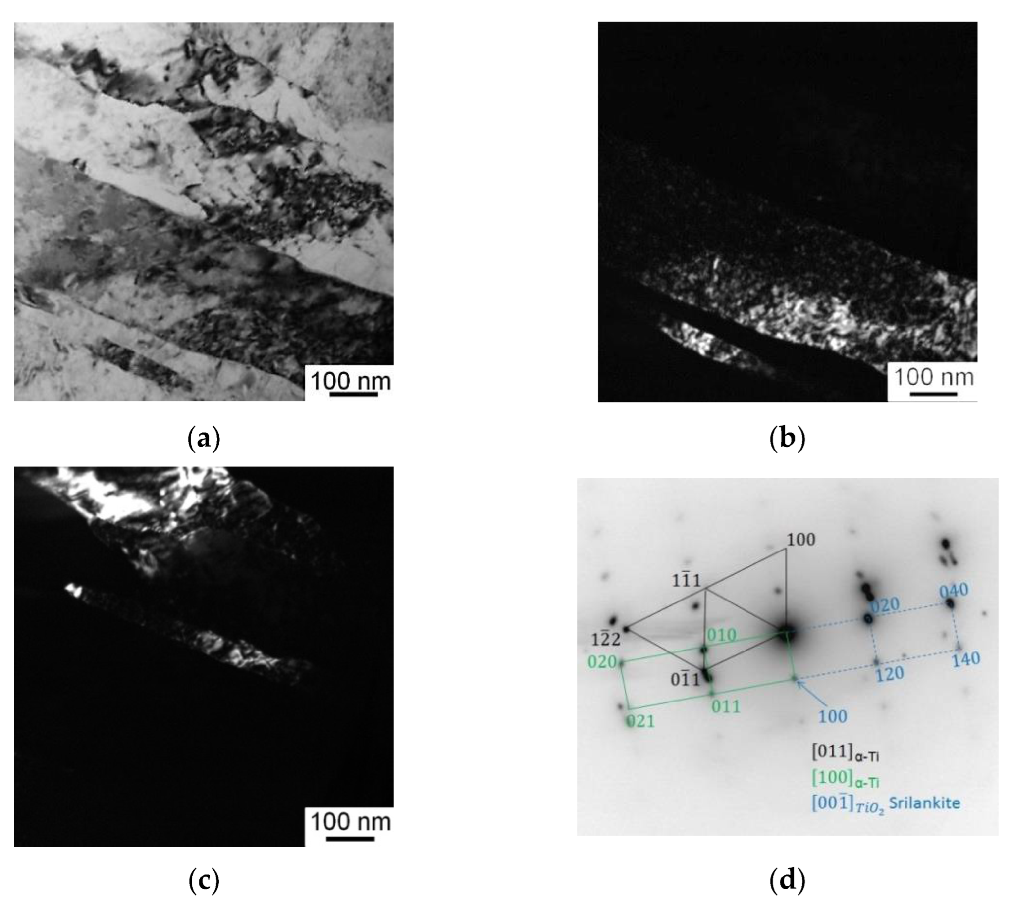
The enlarged view of the β-Ti interlayers that have undergone β→α and β→α″ phase transformations is presented in
Figure 8a. The electron diffraction pattern, which was taken using the gate diaphragm 300 nm in diameter, exhibits strong reflections belonging to the α and α″ phases (
Figure 8b). The α″ phase has lath morphology, its width does not exceed 10 nm, and its length is less than 100 nm which corresponds to the width of the β-Ti interlayers.
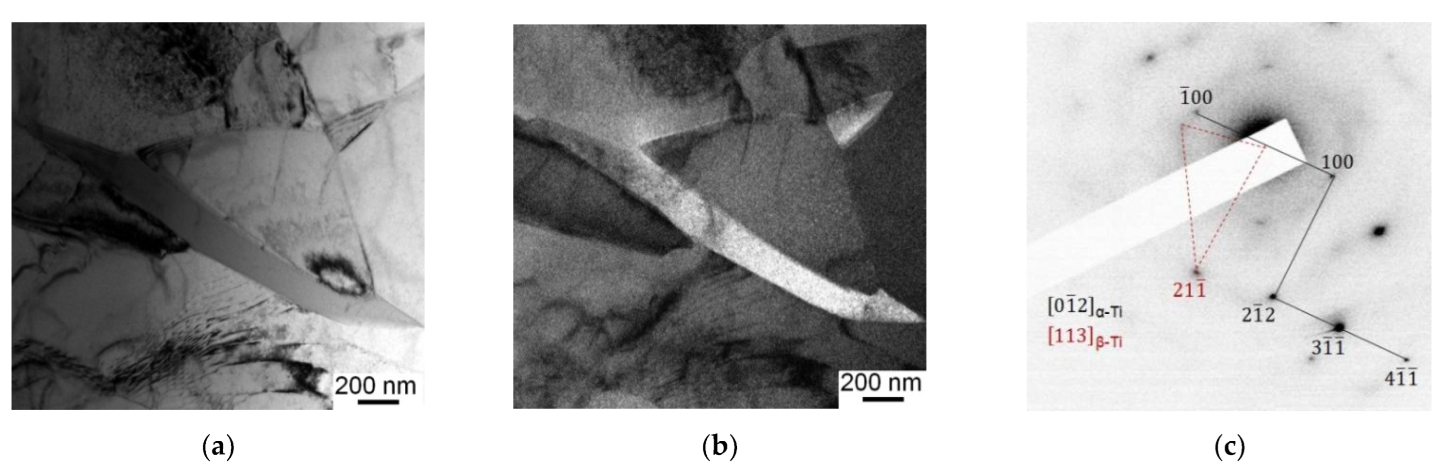
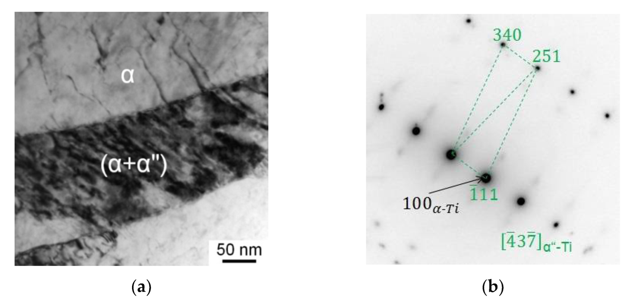
The TEM micrographs obtained at a depth of 75 μm below the surface of the Ti-6Al-4V samples subjected to UIT are characterized by α-Ti grain-subgrain structure with an average subgrain size of 0.5 µm and β-Ti grains located along boundaries or in triple junctions of the α grains (
Figure 9) It is worth noting that a large number of extinction contours are observed within the α grains, indicating a high level of internal stresses and lattice distortions.
6. Discussion
The formation of the α″ phase in titanium alloys is concerned with the presence of β-stabilizing elements (Mo, V, Nb, etc.), which form a continuous series of solid solutions with β-Ti, but have low solubility in α-Ti. As a consequence, the martensitic α″ phase can form under tempering of β titanium alloys, which, in fact, is an oversaturated solid solution based on α-Ti. It should be noted that the β→α″ martensitic transformation is energetically favourable only at a certain content of the β-stabilizing elements, which substantially exceeds their maximum solubility in the hcp lattice, but is insufficient to form the stable bcc lattice. According to the ab initio calculations [
34], the α″ phase is energetically favourable in the Ti-V system at vanadium contents from 9.5 to 20.7 at.%.
As a rule, the strain-induced β→α″ martensitic transformations are also observed in metastable β titanium alloys subjected to tempering followed by tension [
35,
36], compression [
37] or torsion [
38]. The development of the β→α″ transformations in the studied Ti-6Al-4V samples subjected to UIT is concerned with metastability of the retained β phase owing to the presence of oxygen. Oxygen as an α-stabilizer partially compensates for the β-stabilizing effect of vanadium. It should be noted that the experimentally observed β→α″ transformation and the theoretically predicted β→α transformation are not contradictory, since the orthorhombic α″ phase results from the incomplete β→α transformation in conditions of lack of vanadium or presence of oxygen.
The development of phase transformations in titanium and its alloys under thermal and mechanical loading is caused by the redistribution of 3d and 4s valence electrons in titanium atoms. The clearest example of the phase transformations in titanium is the transformation of the low-temperature hcp phase into the high-temperature bcc phase. Electron configuration of titanium atoms is [Ar] 3d24s2. At low temperatures, the outer s-electrons screen the inner electrons that prevent the interaction (overlapping) of valence d-orbitals. Spherically symmetric distribution of electron density of the outer 4s-orbital provides the formation of the close-packed lattice with the coordination number k = 12. An increase in the energy of the electron gas with increasing temperature above 882 °C leads to the transition of one s-electron from the outer 4s-orbital to the 3d-orbital, which is characterized by higher energy. As a consequence, the degree of the overlapping changes leads to an increase in covalency of bonding between Ti atoms and the formation of the bcc lattice with the coordination number k = 8.
Vanadium atoms, which electron configuration is [Ar] 3d
34s
2, have one more
d-electron than titanium atoms. When substituting some titanium atoms with vanadium atoms, the number of electrons at the
d-orbitals of the Ti-V system increases leading to increasing covalency of atomic bonds even without excitation of the electron subsystem, i.e., without electron transitions from 4s to 3d orbital. As a result, a titanium alloy containing vanadium can have a high-temperature bcc lattice even at room temperature. On the contrary, oxygen atoms ([He] 2s
22p
4), as well as aluminium atoms ([Ar] 3s
23p
1) can capture valence electrons of less electronegative titanium [
39], providing the maintenance of the low-temperature hcp lattice at temperatures above 882 °C.
Dislocation pile-ups in the surface layer of the Ti-6Al-4V sample subjected to UIT do not considerably affect the electronic structure and interatomic interaction in the hcp and bcc lattices, but result in their strong distortion. Oxygen atoms occupying octahedral interstitial sites in the bcc lattice lead to even more distortion [
40]. In addition, the presence of oxygen strengthens the Ti-Ti bonds and decreases the covalency of the bonds in the β-phase. As a consequence, shear stresses developed in the Ti-6Al-4V sample during UIT can lead to the development of the β→α″ martensitic transformation in the interlayers of the retained β phase. Since in deficiency of vanadium the value of the total energy of the α″ phase is lower than the full energy of the α and β phases regardless of their atomic volume (
Figure 11b,c), the orthorhombic structure of titanium still remains after unloading.
The formation of new phases in the α grains of the Ti-6Al-4V samples subjected to UIT is not observed experimentally. Earlier [
4], using MD simulation only individual clusters of the bcc phase in the areas of high lattice distortions of the model hcp crystallite were found. The absence of strain-induced phase transformations in the α grains of the Ti-6Al-4V samples subjected to UIT is concerned with the fact that oxygen increases the metallicity of chemical bonding in the bcc lattice enhancing its thermal and mechanical stability [
39]. In addition, the dimensions of octahedral interstitials in the hcp lattice are considerably larger than in the bcc lattice, which results in higher solubility of oxygen in the α phase and does not lead to strong distortions of the hcp lattice.
It is important to note that the presence of oxygen is the reason for different phase transformations revealed experimentally using MD simulation. The effect of oxygen in the MD simulation was considered only through insufficiently high vanadium content (20 at.%) in the bcc lattice of titanium, whereas its distortions were not considered. As a consequence, the β→α transformation was revealed in the simulation. Evidently, the distortions of the bcc lattice induced by the incorporation of oxygen are responsible for the experimentally observed formation of the martensitic α″ phase in the interlayers of the retained β phase of the Ti-6Al-4V samples subjected to UIT.
Dislocation pile-ups in the surface layer of the Ti-6Al-4V samples subjected to UIT result in the fragmentation and disorientation of hcp and bcc crystal lattices observed experimentally and in the MD simulation. However, the formation of nanosized grains with distorted crystal lattices prevents cooperative displacements of atoms induced by shear stresses and, consequently, hinders the development of the β→α″ martensitic transformations. Therefore, the volume fraction of the α″ phase in the Ti-6Al-4V samples subjected to multiple actions of a striker is small and this phase is experimentally observed only at a distance from the treated surface.
Author Contributions
Conceptualization, A.P.; software, A.D., A.N., A.B. and S.K.; investigation, O.P. and L.K.; writing—original draft preparation, A.P. and A.D.; writing—review and editing, A.P., A.D., O.P. and A.B. All authors have read and agreed to the published version of the manuscript.
Funding
The work was performed according to the Government research assignment for ISPMS SB RAS, Projects №№ FWRW-2021-0010, FWRW-2021-06. The investigations have been carried out using the equipment of Share Use Centre “Nanotech” of the ISPMS SB RAS.
Institutional Review Board Statement
Not applicable.
Informed Consent Statement
Not applicable.
Data Availability Statement
The data presented in this study are available on request from the corresponding author.
Conflicts of Interest
The authors declare no conflict of interest.
References
- Statnikov, E.S.; Korolkov, O.V.; Vityazev, V.N. Physics and Mechanism of Ultrasonic Impact. Ultrasonics 2006, 44, e533–e538. [Google Scholar] [CrossRef]
- Panin, A.V.; Kazachenok, M.S.; Kozelskaya, A.I.; Hairullin, R.R.; Sinyakova, E.A. Mechanisms of Surface Roughening of Commercial Purity Titanium during Ultrasonic Impact Treatment. Mater. Sci. Eng. A 2015, 647, 43–50. [Google Scholar] [CrossRef]
- Panin, A.V.; Kazachenok, M.S.; Kozelskaya, A.I.; Balokhonov, R.R.; Romanova, V.A.; Perevalova, O.B.; Pochivalov, Y.I. The Effect of Ultrasonic Impact Treatment on the Deformation Behavior of Commercially Pure Titanium under Uniaxial Tension. Mater. Des. 2017, 117, 371–381. [Google Scholar] [CrossRef]
- Panin, A.; Dmitriev, A.; Nikonov, A.; Kazachenok, M.; Perevalova, O.; Sklyarova, E. Transformations of the Microstructure and Phase Compositions of Titanium Alloys during Ultrasonic Impact Treatment. Part I. Commercially Pure Titanium. Metals 2021, 11, 562. [Google Scholar] [CrossRef]
- Dekhtyar, A.I.; Mordyuk, B.N.; Savvakin, D.G.; Bondarchuk, V.I.; Moiseeva, I.V.; Khripta, N.I. Enhanced Fatigue Behavior of Powder Metallurgy Ti–6Al–4V Alloy by Applying Ultrasonic Impact Treatment. Mater. Sci. Eng. A 2015, 641, 348–359. [Google Scholar] [CrossRef]
- Walker, P.; Malz, S.; Trudel, E.; Nosir, S.; ElSayed, M.S.; Kok, L. Effects of Ultrasonic Impact Treatment on the Stress-Controlled Fatigue Performance of Additively Manufactured DMLS Ti-6Al-4V Alloy. Appl. Sci. 2019, 9, 4787. [Google Scholar] [CrossRef] [Green Version]
- Liu, C.; Chen, D.; Hill, M.R.; Tran, M.N.; Zou, J. Effects of Ultrasonic Impact Treatment on Weld Microstructure, Hardness, and Residual Stress. Mater. Sci. Technol. 2017, 33, 1601–1609. [Google Scholar] [CrossRef] [Green Version]
- Yang, Y.; Jin, X.; Liu, C.; Xiao, M.; Lu, J.; Fan, H.; Ma, S. Residual Stress, Mechanical Properties, and Grain Morphology of Ti-6Al-4V Alloy Produced by Ultrasonic Impact Treatment Assisted Wire and Arc Additive Manufacturing. Metals 2018, 8, 934. [Google Scholar] [CrossRef] [Green Version]
- Liu, S.; Shin, Y.C. Additive Manufacturing of Ti6Al4V Alloy: A Review. Mater. Des. 2019, 164, 107552. [Google Scholar] [CrossRef]
- Shahmir, H.; Langdon, T.G. An Evaluation of the Hexagonal Close-Packed to Face-Centered Cubic Phase Transformation in a Ti-6Al-4V Alloy during High-Pressure Torsion. Mater. Sci. Eng. A 2017, 704, 212–217. [Google Scholar] [CrossRef] [Green Version]
- Panin, V.E.; Panin, A.V.; Perevalova, O.B.; Shugurov, A.R. Mesoscopic Structural States at the Nanoscale in Surface Layers of Titanium and Its Alloy Ti-6Al-4V in Ultrasonic and Electron Beam Treatment. Phys. Mesomech. 2019, 22, 345–354. [Google Scholar] [CrossRef]
- Vasylyev, M.O.; Prokopenko, G.I.; Voloshko, S.M.; Yatsenko, L.F.; Khripta, N.I. Mechanical Properties, Phase and Chemical Compositions of a Surface of the Ti–6Al–4V Alloy After Ultrasonic Impact Treatment in Chemically Active and Neutral Mediums. Metallofiz. Noveishie Tekhnol. 2018, 40, 1029–1049. [Google Scholar] [CrossRef] [Green Version]
- Surikova, N.; Panin, V.; Narkevich, N.; Surikov, N.; Galchenko, N. Formation of Nanocrystalline Structures by Ultrasonic Impact Treatment and Their Effect on Mechanical Characteristics of Steels and Alloys. AIP Conf. Proc. 2020, 2310, 020333. [Google Scholar] [CrossRef]
- Paul, W.B. Molecular Dynamics Simulation, Elementary Methods. By J. M. Haile, Wiley, Chichester 1992, 489 Pp., Hardcover, £ 47.50, ISBN 0-471-81966-2. Adv. Mater. 1993, 5, 223–224. [Google Scholar] [CrossRef]
- Cheong, W.C.D.; Zhang, L.C. Molecular Dynamics Simulation of Phase Transformations in Silicon Monocrystals Due to Nano-Indentation. Nanotechnology 2000, 11, 173–180. [Google Scholar] [CrossRef] [Green Version]
- Hua, D.; Xia, Q.; Wang, W.; Zhou, Q.; Li, S.; Qian, D.; Shi, J.; Wang, H. Atomistic Insights into the Deformation Mechanism of a CoCrNi Medium Entropy Alloy under Nanoindentation. Int. J. Plast. 2021, 142, 102997. [Google Scholar] [CrossRef]
- Shugurov, A.R.; Panin, A.V.; Dmitriev, A.I.; Nikonov, A.Yu. Recovery of Scratch Grooves in Ti-6Al-4V Alloy Caused by Reversible Phase Transformations. Metals 2020, 10, 1332. [Google Scholar] [CrossRef]
- Shugurov, A.; Panin, A.; Kazachenok, M.; Kazantseva, L.; Martynov, S.; Bakulin, A.; Kulkova, S. Deformation Behavior of Wrought and EBAM Ti-6Al-4V under Scratch Testing. Metals 2021, 11, 1882. [Google Scholar] [CrossRef]
- Shugurov, A.R.; Nikonov, A.Y.; Dmitriev, A.I. The Effect of Electron-Beam Treatment of the Deformation Behavior of EBAM Ti-6Al-4V under Scratching. Facta Univ. Ser. Mech. Eng. 2022, 1–13. [Google Scholar] [CrossRef]
- Panin, A.V.; Kazachenok, M.S.; Dmitriev, A.I.; Nikonov, A.Y.; Perevalova, O.B.; Kazantseva, L.A.; Sinyakova, E.A.; Martynov, S.A. The Effect of Ultrasonic Impact Treatment on Deformation and Fracture of Electron Beam Additive Manufactured Ti-6Al-4V under Uniaxial Tension. Mater. Sci. Eng. A 2022, 832, 142458. [Google Scholar] [CrossRef]
- Plimpton, S. Fast Parallel Algorithms for Short-Range Molecular Dynamics. J. Comput. Phys. 1995, 117, 1–19. [Google Scholar] [CrossRef] [Green Version]
- Dmitriev, A.I.; Nikonov, A.Yu.; Shugurov, A.R.; Panin, A.V. The Role of Grain Boundaries in Rotational Deformation in Polycrystalline Titanium under Scratch Testing. Phys. Mesomech. 2019, 22, 365–374. [Google Scholar] [CrossRef]
- Dmitriev, A.I.; Nikonov, A.Yu.; Shugurov, A.R.; Panin, A.V. Numerical Study of Atomic Scale Deformation Mechanisms of Ti Grains with Different Crystallographic Orientation Subjected to Scratch Testing. Appl. Surf. Sci. 2019, 471, 318–327. [Google Scholar] [CrossRef]
- Alabd Alhafez, I.; Urbassek, H.M. Scratching of Hcp Metals: A Molecular-Dynamics Study. Comput. Mater. Sci. 2016, 113, 187–197. [Google Scholar] [CrossRef]
- Maisel, S.B.; Ko, W.-S.; Zhang, J.-L.; Grabowski, B.; Neugebauer, J. Thermomechanical Response of NiTi Shape-Memory Nanoprecipitates in TiV Alloys. Phys. Rev. Mater. 2017, 1, 033610. [Google Scholar] [CrossRef] [Green Version]
- Stukowski, A.; Bulatov, V.V.; Arsenlis, A. Automated Identification and Indexing of Dislocations in Crystal Interfaces. Model. Simul. Mater. Sci. Eng. 2012, 20, 085007. [Google Scholar] [CrossRef]
- Blöchl, P.E. Projector Augmented-Wave Method. Phys. Rev. B 1994, 50, 17953–17979. [Google Scholar] [CrossRef] [Green Version]
- Kresse, G.; Joubert, D. From Ultrasoft Pseudopotentials to the Projector Augmented-Wave Method. Phys. Rev. B 1999, 59, 1758–1775. [Google Scholar] [CrossRef]
- Perdew, J.P.; Burke, K.; Ernzerhof, M. Generalized Gradient Approximation Made Simple. Phys. Rev. Lett. 1996, 77, 3865–3868. [Google Scholar] [CrossRef] [Green Version]
- Panin, A.; Kazachenok, M.; Perevalova, O.; Kolmakov, A. Surface Modification of EBF3-Fabricated Ti–6Al–4V Parts by Ultrasonic Impact Treatment. AIP Conf. Proc. 2020, 2310, 020244. [Google Scholar] [CrossRef]
- Kameyama, Y.; Komotori, J. Effect of Micro Ploughing during Fine Particle Peening Process on the Microstructure of Metallic Materials. J. Mater. Processing Technol. 2009, 209, 6146–6155. [Google Scholar] [CrossRef]
- Fitzner, A.; Palmer, J.; Gardner, B.; Thomas, M.; Preuss, M.; da Fonseca, J.Q. On the Work Hardening of Titanium: New Insights from Nanoindentation. J. Mater. Sci. 2019, 54, 7961–7974. [Google Scholar] [CrossRef] [Green Version]
- Pantawane, M.V.; Dasari, S.; Mantri, S.A.; Banerjee, R.; Dahotre, N.B. Rapid Thermokinetics Driven Nanoscale Vanadium Clustering within Martensite Laths in Laser Powder Bed Fused Additively Manufactured Ti6Al4V. Mater. Res. Lett. 2020, 8, 383–389. [Google Scholar] [CrossRef]
- Panin, A.; Martynov, S.; Kazachenok, M.; Kazantseva, L.; Bakulin, A.; Kulkova, S.; Perevalova, O.; Sklyarova, E. Effects of Water Cooling on the Microstructure of Electron Beam Additive-Manufactured Ti-6Al-4V. Metals 2021, 11, 1742. [Google Scholar] [CrossRef]
- Duerig, T.W.; Albrecht, J.; Richter, D.; Fischer, P. Formation and Reversion of Stress Induced Martensite in Ti-10V-2Fe-3Al. Acta Metall. 1982, 30, 2161–2172. [Google Scholar] [CrossRef]
- Lee, B.S.; Im, Y.D.; Kim, H.G.; Kim, K.H.; Kim, W.Y.; Lim, S.H. Stress-Induced A″ Martensitic Transformation Mechanism in Deformation Twinning of Metastable β-Type Ti-27Nb-0.5Ge Alloy under Tension. Mater. Trans. 2016, 57, 1868–1871. [Google Scholar] [CrossRef] [Green Version]
- Ma, X.; Chen, Z.; Xiao, L.; Lu, W.; Luo, S.; Mi, Y. Compressive Deformation of a Metastable β Titanium Alloy Undergoing a Stress-Induced Martensitic Transformation: The Role of β Grain Size. Mater. Sci. Eng. A 2020, 794, 139919. [Google Scholar] [CrossRef]
- Ma, X.; Li, F.; Sun, Z.; Hou, J.; Fang, X.; Zhu, Y.; Koch, C.C. Achieving Gradient Martensite Structure and Enhanced Mechanical Properties in a Metastable β Titanium Alloy. Met. Mat. Trans A 2019, 50, 2126–2138. [Google Scholar] [CrossRef]
- Hennig, R.G.; Trinkle, D.R.; Bouchet, J.; Srinivasan, S.G.; Albers, R.C.; Wilkins, J.W. Impurities Block the α to ω Martensitic Transformation in Titanium. Nat. Mater. 2005, 4, 129–133. [Google Scholar] [CrossRef] [Green Version]
- Salloom, R.; Reith, D.; Banerjee, R.; Srinivasan, S.G. First Principles Calculations on the Effect of Interstitial Oxygen on Phase Stability and β–A″ Martensitic Transformation in Ti–Nb Alloys. J. Mater. Sci. 2018, 53, 11473–11487. [Google Scholar] [CrossRef]
Figure 1.
Picture of the designed automated UIT setup.
Figure 2.
TEM bright-field image (a) and associated selected area electron diffraction (SAED) pattern (b) of the microstructure of the uppermost surface layer of the Ti-6Al-4V sample subjected to UIT.
Figure 3.
STEM images of the microstructure of the Ti-6Al-4V samples subjected to UIT. The micrographs were obtained at a depth of 5 (a), 45 (b) and 75 μm below the treated surface (c).
Figure 4.
TEM bright- (a,b) and dark-field (c) images and an associated SAED pattern with an indexing scheme (d) of the microstructure of the Ti-6Al-4V samples subjected to UIT. The TEM micrographs were obtained at a depth of 5 μm below the treated surface. The dark-field micrograph was obtained with the α-Ti reflection.
Figure 5.
TEM bright- (a) and dark-field (b–d) images and an associated SAED pattern with an indexing scheme (e) illustrating the microstructure of the Ti-6Al-4V samples subjected to UIT. The TEM micrographs were obtained at a depth of 10 μm below the treated surface. The dark-field micrographs were obtained with the α-Ti (b), α″-Ti (c) and β-Ti (d) reflections.
Figure 6.
TEM bright- (a) and dark-field (b,c) images and an associated SAED pattern (d) illustrating the microstructure the of Ti-6Al-4V samples subjected to UIT. The TEM micrographs were obtained at a depth of 45 μm below the treated surface. The dark-field micrographs were obtained with the 011 α-Ti (b) and α-Ti (c) reflections.
Figure 7.
TEM bright- (a) and dark-field (b,c) images and an associated SAED pattern with an indexing scheme (d,e) illustrating the microstructure of the Ti-6Al-4V samples subjected to UIT. The micrographs were obtained at a depth of 45 μm below the treated surface. The dark-field micrographs were obtained with the β-Ti (b) and α″-Ti (c) reflections.
Figure 8.
TEM bright-field image (a) and an associated SAED pattern (b) illustrating the microstructure of the Ti-6Al-4V samples subjected to UIT. The micrographs were obtained at a depth of 45 μm below the treated surface.
Figure 9.
TEM bright- (a) and dark-field (b) images and an associated SAED pattern (c) illustrating the microstructure of the Ti-6Al-4V samples subjected to UIT. The micrographs were obtained at a depth of 75 μm below the treated surface. The dark-field micrographs were obtained with the β-Ti reflection.
Figure 10.
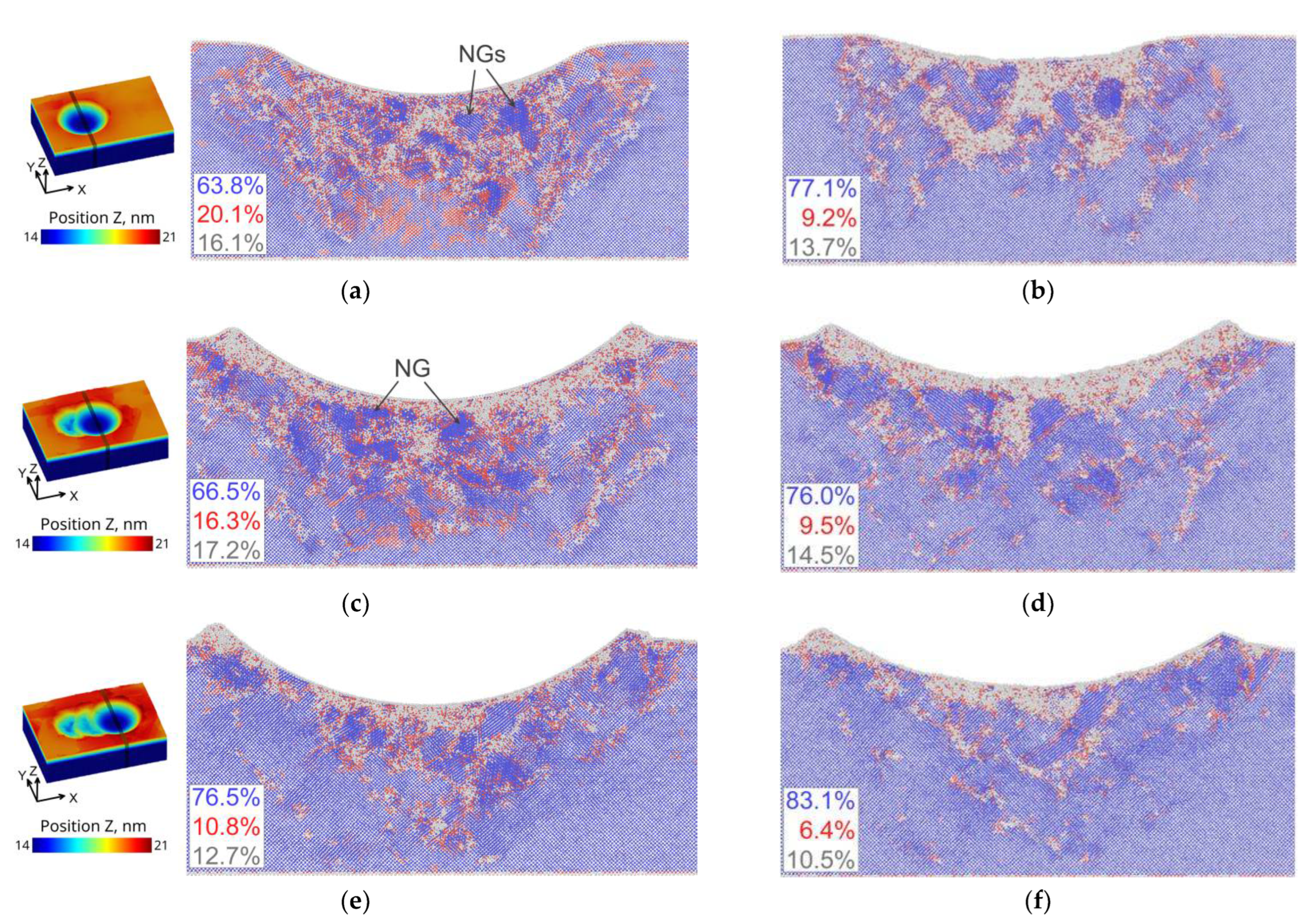
Cross-sectional snapshots (projection onto the YZ plane in the middle of the indentation imprint, exact positions are shown at the left panel) illustrating the microstructure of the bcc-Ti crystallite containing 20 at.% of vanadium under applying the maximum load (a,c,e) and after unloading (b,d,f) for the first (a,b), second (c,d) and third (e,f) indentations. The color of atoms corresponds to different local configurations of the atomic lattice according to CNA: bcc atoms are shown blue, hcp atoms are shown red, and atoms belonging to an unidentified lattice are shown grey. The volume fraction of the atoms is given in the lower right corner by blue, red and gray colors correspondingly.
Figure 11.
Total energy vs. atomic volume for the α, β and α″ phases of titanium containing 6.25 (a), 12.5 (b), 18.75 (c) and 25.0 at.% (d) of vanadium.
Table 1.
Chemical composition of Ti-6Al-4V titanium alloy.
| Elements | Al | V | Fe | O | N | C | Ti |
|---|
| (wt.%) | 6.6 | 4.0 | 0.1 | 0.2 | 0.05 | 0.03 | Balance |
Table 2.
Elemental composition of the Ti-6Al-4V sample at the points shown in
Figure 7a.
| Element | Point 1, at.% | Point 2, at.% | Point 3, at.% | Point 4, at.% |
|---|
| Ti | 74 | 63 | 58 | 68 |
| Al | 9 | 3 | 3 | 11 |
| V | 2 | 18 | 12 | 2 |
| O | 15 | 16 | 27 | 19 |
| Publisher’s Note: MDPI stays neutral with regard to jurisdictional claims in published maps and institutional affiliations. |
© 2022 by the authors. Licensee MDPI, Basel, Switzerland. This article is an open access article distributed under the terms and conditions of the Creative Commons Attribution (CC BY) license (https://creativecommons.org/licenses/by/4.0/).


 ,
, 


